

Submitted:
28 July 2026
Posted:
29 July 2026
You are already at the latest version
Abstract
This simulation-based case study investigates vehicle handling performance during severe asymmetric and symmetric tire inflation pressure loss, comparing self-supporting run-flat tires (SSRFT) to conventional radial configurations. To capture the complex coupled interactions occurring under severe pressure depletion, this work introduces a non-linear 9-Degree-of-Freedom (9-DOF) multi-body dynamics numerical simulation framework parameterized to an F56 MINI Cooper S platform. The mathematical plant model expands upon classical planar approximations by fully integrating dynamic chassis roll, pitch, and four independent wheel spin rotational degrees of freedom. The core tire-road interface is parameterized using empirical constants parsed from a proprietary Michelin Magic Formula 6.2 (.tir) baseline data file acquired through manufacturer collaboration. Because physical test-rig boundaries prohibit zero-pressure execution, unpressurized (0 kPa) carcass-only structural degradation profiles and sidewall stiffness retention indices are formulated based on hyperelastic limits from literature. To eliminate human driver variability and bypass the limitations of open-loop steering inputs, path tracking is governed by a closed-loop, two-point preview Stanley steering control algorithm. The vehicle model is subjected to the strict spatial corridor constraints of an unthrottled ISO 3888-2 double-lane change maneuver at an entry speed of 80 km/h under an unthrottled inertial speed decay regime. To map the true limits of structural failures, three distinct puncture topologies are evaluated sequentially: asymmetric Front-Left (FL) deflation, asymmetric Front-Right (FR) deflation, and symmetric dual front-axle deflation. A complete parametric sensitivity analysis is performed on the primary tracking gains to isolate structural tire behavior from the guidance loop. Quantitative model-based observations demonstrate that while conventional radial plies enter rapid understeer saturation and continuous contact patch sliding, the structural sidewall insert rubber (SIR) of the SSRFT maintains stable handling margins and minimizes lateral track errors. These quantified performance variations provide baseline metrics to inform virtual vehicle prototyping and parametric chassis control tuning.
Keywords:
tire modeling
; modeling
; simulation
; automotive engineering
; vehicle dynamics
; handling
; run-flat tires
1. Introduction
All forces and moments acting on a vehicle—with the exception of the aerodynamic forces—are caused by the interacting interface between the pneumatic tire and the road surface; therefore, the study and comprehension of the pneumatic tire and the phenomena that take place at this surface area are essential.
The forces and moments generated at the tire-road interface are essential for quantifying vehicle performance with respect to energy efficiency, directional handling, and ride comfort. Furthermore, the intrinsic mechanical properties of the tire, such as structural rigidity, damping characteristics, and material composition, are fundamental to analyzing the transient dynamic behavior of motor vehicles.
It is important to emphasize that the functions of the tire in the vehicle are: supporting the load of the vehicle and the occupants, providing damping to the vehicle’s structure, transmitting driving forces—such as braking and accelerating—and, lastly, guaranteeing an acceptable adherence to the road surface. The conventional pneumatic tires can easily carry out these tasks, which is why most modern vehicles utilize them.
Radial tires, which in this document will be known as conventional tires, offer a high level of comfort and are relatively less expensive; however, they have limitations due to their dependence on internal air pressure. When they are punctured, they can no longer maintain vertical loads or create lateral forces, often resulting in compromised vehicle control or lateral drift during high-speed turns [1]. As an alternative, the automotive industry introduced run-flat tires (RFT) that promise the ability to continue rolling when the inflation pressure is lost. The RFT is essentially a reinforced radial tire since its construction is similar, with the addition of a sidewall insert rubber (SIR). Even in the absence of air pressure, the RFTs are able to continue rolling for a limited time and pace ( at ). These specialized tires are divided into two main types: self-supporting (SSRFT) and auxiliary-supported systems. SSRFT use thickened sidewall geometries to maintain structural stability without any air pressure. This study will focus on the SSRFT variant.
The structural durability of the SSRFT is maintained by using a SIR, enabling the tire to carry the vehicle’s weight even after losing all the air pressure. Recent studies on SIR configuration show that the vertical location of the inserts influences radial stiffness more than their thickness does, which is vital information for designing tires that perform well whether inflated or not. Although RFTs provide high safety advantages, they also present difficulties, including increased vertical stiffness that may result in greater stress on wheel rims [2,3,4].
Pacejka’s Magic Formula (MF) is crucial for determining the vehicle’s control limit and accurately estimating tire behavior during intense maneuvers in contemporary vehicle dynamics. For example, when a regular tire loses air, its coefficients change significantly, resulting in a flattened lateral force curve that leads to steering saturation. In contrast, SSRFTs retain a much larger proportion of their original stiffness factor and peak value even when deflated, minimizing steering saturation tendencies under transient loading [5,6].
This mathematical model undergoes severe evaluation during the ISO 3888-2 maneuver, also known as the Moose Test. This specific test forces the vehicle to execute a rapid and extreme double-lane change, emulating the need to avoid an unexpected obstacle on a road before returning to its initial lane. Unlike general handling tests, the ISO 3888-2 layout features narrow target corridors and requires the driver to completely lift off the throttle, creating a demanding evaluation of a vehicle’s transient stabilization and roll indices [7]. Comparative simulation studies reveal that while a vehicle using completely deflated conventional tires undergoes severe understeer saturation and drifts wide of the gate corridors, a vehicle equipped with self-supporting run-flat tires leverages its mechanical sidewall reinforcements to minimize path tracking errors and safely maintain course within the narrow designated track boundaries [1,7].
The following study originates from the need to address the common practice found among BMW and MINI Cooper owners of removing the factory fitted SSRFT from their vehicles in an attempt to improve handling and comfort. In addition, this is done to reduce expenses since SSRFT can cost up to double the price of conventional tires. Also, it is expected that this work can provide valuable information for the design of control systems that are used in vehicles equipped with SSRFT.
While the general qualitative behavior of SSRFT layouts under zero-pressure conditions has been broadly documented in structural literature, numerical vehicle dynamics models frequently suffer from severe fidelity truncations. These simplifications typically assume a constant forward velocity, omit dynamic suspension pitch coupling, or apply symmetric 4-wheel failure profiles that obscure the directional tracking asymmetries caused by single-point deflations. Furthermore, the underlying Magic Formula tire coefficients in simulation literature are often generalized from non-disclosed datasets, introducing empirical uncertainty into the friction ceilings.
To bridge this research gap, this simulation-based case study provides a clearly differentiated contribution to the vehicle dynamics literature across four core pillars:
- 1.
- Empirical Parameterization: The initialization of the healthy nominal baseline tire model utilizes genuine empirical data extracted from a proprietary Michelin Magic Formula 6.2 property file, secured via academic-manufacturer data sharing.
- 2.
- Plant Model Fidelity (9-DOF): The formulation of an explicit 9-DOF multi-body numerical model that actively integrates non-linear cross-weight roll and pitch mass transformations alongside four separate wheel rotational speed states, replacing classical algebraic slip shortcuts.
- 3.
- Advanced Path Tracking: The integration of a closed-loop, two-point preview Stanley control law capable of compensating for localized chassis sideslip and yaw-rate damping variations during transient transitions.
- 4.
- Puncture Topology Isolation: A sequential evaluation matrix that separates asymmetric individual wheel blowouts (FL versus FR) from symmetric whole-axle failures (Dual Front), exposing the directional handling imbalances caused by transient lateral load transfer.
This investigation is organized into VIII primary sections. Section II provides a comprehensive literature review. Section III outlines the methodology and overarching simulation architecture. Section IV details the non-linear 9-DOF full-vehicle plant dynamics and semi-empirical tire modeling equations. Section V describes the closed-loop driver guidance model and controller validation. Section VI and Section VII present the vehicle parameterization and multi-variable simulation telemetry results, respectively. Finally, Section VIII provides concluding remarks and outlines future research boundaries.
2. Literature Review
The main part of the literature review is dissected in Table 1, where the principal insight gathered from the extensive literature review performed is tabulated. A breakdown of that process is described below, and its divided into three main sections.
2.1. Rubber Composites and Sidewall Reinforcement
The initial phase of this research entailed a comprehensive and critical review of the available scientific literature. The approach was a deep dive into the theoretical and practical studies and comparisons previously written about the pneumatic tire and the development of aids to minimize the negative effects of losing the supporting air inflation pressure. The first takeaway from this research is that the concept of a self-supporting tire is by no means a novel subject. Since it made its appearance back in the 70’s [1], the SSRFT has been in continuous evolution together with the modernization of the radial tire, ranging from double chambers, foam fillings, thickened surfaces, and the airless tire, that consists of an open sidewall tire featuring radial supports that act like stiff springs to support the vehicle’s weight. Despite these mechanical developments, the structural configuration remains limited in lateral force generation, and it is, for now, restricted to low speed vehicles and niche applications.
The development of innovative structural design for the SSRFT relies strongly on optimized geometries and hyperelastic modeling. It was established by Lv [4] that a SIR thickness of is the best compromise between added overall mass to the tire and vertical load bearing capability obtaining optimized stress matrices under zero inflation pressure. Expanding on the mechanical stresses study, Zang [8] showed that even when the total contact patch of a tire without inflation pressure expands by , the effective contact patch contracts by . This occurs mainly because the load concentrates to the sides and the contact patch warps generating localized zones of stress and friction that degrade the tire’s constitution and performance. To mathematically capture the stress in these zones, Lv [4] created a simulation based on the Mooney-Rivlin hyperelastic model that formulated stress-strain tensors. This yielded material behavior constants for the rigid elastomer matrices of the tire when rolling at low inflation pressure.
Recent research shifts its focus from the geometric optimization of the sidewall to the chemical composition of the elastomer matrix. Taking advantage of advancements in material science, Okan [9] proved that replacing up to of the commonly used carbon black reinforcement with graphene nanofibers produces a balance in the classic "Magic Triangle" paradigm shown in Figure 1 improving durability or wear resistance without compromising rolling resistance. Outside of self-supporting reinforcement options Testa [10] simulated and prototyped a disjointed radial HeroBelt rim assembly as an alternative backup system that utilizes an auxiliary wheel to support the vehicle in the event of pressure loss. Shedding light on how the modular belt proposal isolates and dissipates extreme thermal friction.
2.2. Tire Modeling and the Magic Formula
The interactions that occur on the contact patch under extreme slip conditions () require complex analysis, and in order to mathematically predict the forces and moments that are involved, semi empirical modeling remains the industry standard. The model defined by Pacejka’s MF [5] derived the lateral forces and moments in the tire-road interaction, accurately capturing the non-linear behavior of the tires and from which, modern vehicle simulations get their algebraic boundaries. These forces are dynamically altered when a loss of air pressure occurs. Because of this, Singh [6] presented an extended MF framework that utilized real time adaptive parameter fitting loops to adjust the tire’s compliance matrix dynamically during sudden pressure losses.
Because of the structure of the radial tire, the contact patch behavior changes drastically when a tire experiences a total drop in air pressure. Mahajan [1] performed simulations based on Pacejka’s MF, showcasing that conventional tires yield tracking errors of up to in the absence of inflation pressure. On the other hand, an SSRFT limits these path deviations to less than . Using triaxial grid modeling, Guo [11] mapped the physical mechanics driving the path deviation variations by showing how a combination of severe braking vectors shifts the contact stress concentration zone to the front of the contact patch.
2.3. Standardized Handling Evaluation and Simulation Constraints
In order to evaluate the transient stability boundaries of asymmetric inflation pressure drops, the optimal procedure is a standardized closed-loop obstacle avoidance maneuver, such as the double-lane change layout outlined in the international standard ISO 3888-2 [7]. In the virtual testing environment, navigating the high-speed transient gates of the track requires robust multi-constraint trajectory-following logic, as detailed by Nguyen [12]. In the present work, a closed-loop driver model is integrated to guide the non-linear 9-DOF vehicle dynamics plant, utilizing path-following formulations adapted from Rajamani [13].
The multi-body simulation setup relies closely on established vehicle testing baselines. Heerwan [14] evaluated the influence of forward velocity on lateral weight transfer and inertial roll forces during instrumented field trials, which provides the empirical justification for selecting 80 km/h as the initial evaluation entry speed. The core differential equations governing rigid-body chassis translations, yaw accelerations, and multi-axle vertical load shifts are derived from Gillespie [15], while the mathematical models for non-linear tire force generation, pneumatic contact patch slip boundaries, and extreme handling limits are based on Milliken and Milliken [16]. Standard numerical integration subroutines are deployed to benchmark the 9-DOF plant within the geometric target track corridors defined by the ISO 3888-2 specification [7]."
3. Methodology & System Architecture
The overall research design was structured around a multi-stage numerical simulation pipeline. The foundational stage entailed the acquisition of empirical baseline parameters for the tire-road interface. Rather than relying entirely on open-access generic datasets, a proprietary Michelin Magic Formula 6.2 property (.tir) file was sourced and parsed line-by-line within a native Python environment. This high-fidelity dataset serves as the baseline benchmark for the nominally inflated tire configurations (240 kPa).
To characterize the unpressurized (0 kPa) states without inducing numerical instabilities or unphysical curve inversions—common hazards when evaluating empirical fits outside their tested bounds—a physics-guided empirical scaling routine was deployed. Structural stiffness retention factors (25% for conventional carcasses, 70% for run-flat reinforced casings) and contact patch grip degradation ceilings (40% for conventional, 85% for run-flat) were mapped using hyperelastic limits established by Mahajan [1] and Saraswat [17]. This mathematical synthesis yielded a robust, four-scenario parameter matrix spanning all three force and moment channels (, , and ) shown in Figure 2.
The second phase of the methodology shifted from component-level modeling to full-vehicle transient handling evaluation. The developed tire matrices were integrated into a non-linear 9-DOF vehicle plant model. To eliminate human driver execution variability and bypass the limitations of open-loop steering profiles, a closed-loop path-following framework was mandatory. A two-point preview Stanley controller was developed, tracking both an instantaneous cross-track error at the front axle and a future look-ahead error point over a human-centric preview time horizon ( s). This virtual driver dynamically adjusts the front wheel steer angle () to follow the true centerline geometry of the ISO 3888-2 double-lane change layout.
To comprehensively analyze the directional asymmetries induced by inflation loss, the simulation executes three completely independent, sequentially isolated testing groups: 1. Asymmetric Front-Left (FL) Puncture: Evaluating handling degradation when pressure loss occurs exclusively on the front-left wheel hub, while the remaining three corners maintain nominal inflation pressures corresponding to their respective tire specifications. 2. Asymmetric Front-Right (FR) Puncture: Evaluating pressure loss on the front-right wheel hub under an identical multi-corner nominal tire layout. 3. Symmetric Dual Front Puncture: Simulating a full front-axle structural deflation to establish a baseline for uncoupled, purely symmetric handling degradation.
4. System Modeling
4.1. High-Fidelity Tire Force Formulation
The calculation of non-linear contact patch force generation uses a semi-empirical approach based on a parsed Michelin Magic Formula 6.2 specification. The model resolves longitudinal force (), lateral force (), and self-aligning moment () simultaneously. The mathematical structure is governed by four primary parameters: the stiffness factor (B), the shape factor (C), the peak friction ceiling (D), and the curvature modifier (E). The core transcendental equation mapping lateral force output is defined as:
where represents localized wheel corner indices, and is the tire contact patch slip angle converted from radians to degrees.
The baseline nominal scaling coefficients (PDX1, PDY1, PKY1, QDZ1) are extracted from the proprietary Michelin data file. Under inflated conditions (240 kPa), the peak force value (D) scales directly with the time-variant dynamic vertical load () acting on that specific corner:
The initial cornering stiffness slope () is dynamically coupled to load via the opera- tional identity:
To model structural pressure depletion (0 kPa) accurately without mathematical instability or unphysical curve flipping, the script replaces generalized rules of thumb with validated structural carcass overrides. For conventional radial plies, air loss triggers a total collapse of the sidewalls, forcing the peak force ceiling (D) down to 40% of the Michelin nominal reference, and flattening the stiffness factor (B) to 25% due to contact patch wrapping and severe footprint distortion.
For the self-supporting run-flat tire (SSRFT), the vertical weight transfers onto the pre-compressed sidewall insert rubber (SIR), whose hyperelastic parameters ( MPa) prevent complete structural collapse. The deflated SSRFT maintains 85% of its nominal peak friction capacity (D) and preserves 70% of its initial cornering stiffness factor (B), resulting in the stable force tracking profile implemented in the plant loop.
4.2. Complete 9-DOF Governing Equations of Motion
To ensure rigorous validation and address the structural limitations of planar approximations, a complete 9-DOF multi-body dynamics architecture was developed. The plant tracks 5 independent chassis variables—longitudinal speed (u), lateral speed (v), yaw rate (r), suspension roll angle (), and suspension pitch angle ()—fully coupled with 4 independent wheel spin rotational velocity states ().
The governing equations for rigid body translation and yaw rotation relative to the body-fixed center of gravity are derived via Newton-Euler mechanics:
where m is the total vehicle mass (1310 kg), is the yaw moment of inertia (1400 kg·m2), and are the geometric axle distances to the CG, is the track width ( m), and is the front axle steer angle commanded by the closed-loop driver model.
The transient rotational modes of the chassis are resolved through two second-order differential equations that model suspension compliance under high-g centripetal and deceleration load transfers:
where and are the respective roll and pitch moments of inertia, is the sprung mass (1150 kg), is the center of gravity height ( m), and represents the instantaneous lateral acceleration. Total suspension stiffness () and fluid damping coefficients () are parameterized explicitly to the F56 MINI Cooper S stabilizer matrices.
To address the requirements of explicit longitudinal slip tracking and dynamic energy dissipation, the 4 wheel spin degrees of freedom are integrated continuously at 1000 Hz via localized wheel torque balance equations:
where is the wheel rotational inertia ( kg·m2), is the effective rolling radius ( m), and throughout the unthrottled inertial dissipation regime. By integrating at each time-step, the model dynamically resolves the true transient Slip Ratio (SR) at each wheel hub footprint:
where represents the localized linear velocity of individual wheel hubs in their respective tire coordinate frames. This formulation isolates the longitudinal scrubbing drag induced by the severe shape deformations of the deflated tire casings, ensuring true multi-variable coupling across all 9 independent degrees of freedom.
5. Closed-Loop Guidance Logic & Path Architecture
5.1. Advanced Two-Point Preview Guidance Law
To guide the 9-DOF vehicle plant model through the standardized obstacle avoidance test, a closed-loop trajectory-following framework was implemented, replacing all open-loop human steering assumptions. The target track centerline profile () mathematically recreates the exact corridor geometry outlined in the ISO 3888-2 specification across a 61-meter tracking horizon:
Steering commands are calculated by coupling the instantaneous cross-track error () measured at the front axle center line with an advanced look-ahead preview point error () projected over a driver look-ahead horizon ( s) matching realistic human reaction times:
where represents orientation error relative to the localized road heading angle, is the vehicle body sideslip angle, and is the reference track yaw rate dictated by the track curvature. The controller gains () are tuned to achieve optimal path compliance under nominal pressure. The calculated steering vector is subsequently processed through a low-pass first-order integration filter to reflect physical steering actuator lag constraints, bounding the maximum allowable front wheel articulation to a physical structural ceiling of .
5.2. Stanley Controller Parametric Validation and Robustness Sweep
To ensure path-following accuracy and verify the stability of the closed-loop steering framework under transient handling conditions, a parametric sensitivity analysis was conducted on the primary guidance gain, . This coefficient regulates the virtual driver’s steering response to perpendicular cross-track offsets at the front axle hub line. The parameter was sweep-tested across an operational continuum () under an identical nominal standard inflation pressure profile (240 kPa) at an entry speed of 80 km/h.
The computational sweeps reveal that low gain configurations () introduce significant path-following attenuation, as the virtual steering actuator fails to generate adequate corrective feedback torque. This manifests as a delayed turn-in sequence during the first lane change entry (Longitudinal position m to 24 m), causing a peak cross-track overshoot error exceeding 0.65 m. Conversely, excessive gain multipliers () over-excite steering actuator feedback boundaries. While this sharply minimizes initial entry errors, it over-excites the system’s understeer index during the high-g snap back, causing the vehicle to exhibit a high-frequency spatial tracking hunting phenomenon—manifesting as rapid steering corrections around the stabilization lane centerline ( m to 35 m). See Figure 3
The selection of minimizes tracking error bounds beneath 0.05 m across all track segments without introducing numerical or directional instabilities into the 9-DOF multi-body plant equations. Consequently, this optimized value is locked as the constant guidance baseline for all subsequent tire inflation failure sets.
6. Vehicle Platform and Track Environment Parameterization
6.1. Vehicle Physical Parameters
The vehicle data utilized is based on the technical specifications of the [F56] MINI Cooper S and was chosen because it is highly regarded as an agile vehicle with unique handling [18]. Additionally, it comes with SSRFTs from the factory, making it an excellent choice for the study. The full vehicle specifications are listed in Table 2:
6.2. Track Geometry and Specifications
7. Results and Discussion
7.1. Spatial Centerline Center of Gravity Tracking Analysis
All tracking errors reported within this analysis are quantified strictly as perpendicular cross-track displacement measurements from the true road centerline reference trajectory () relative to the vehicle’s rigid center of gravity point. The 9-DOF numerical simulation traces are captured across three sequentially isolated testing protocols. Under baseline nominal pressure conditions (240 kPa), both the conventional reference tire profile and the self-supporting run-flat alternative follow the reference target centerline with high precision, maintaining perpendicular tracking errors well beneath 0.04 m and securing a clean path compliance verification across all gates. See Figure 5.
Under asymmetric Front-Right deflation conditions, the vehicle model undergoes severe understeer saturation during the initial sharp left turn sequence. Because the front-right tire functions as the heavily loaded outer wheel during this first transient transition, its collapsed cornering stiffness matrix compromises lateral force generation. The front axle consequently fails to follow the first cosine transition lane, plowing wide of the target gate corridors and experiencing a peak cross-track trajectory deviation error of 3.80 m.
Conversely, under asymmetric Front-Left deflation conditions, the initial left turn is managed successfully because the fully inflated front-right tire retains full traction. However, during the subsequent right turn into the evasion box (Longitudinal position m to m), the chassis rolls heavily onto the flat front-left wheel. The conventional tire contact patch completely exhausts its available lateral force capacity via Pacejka saturation under the dynamic load transfer, forcing the vehicle model into a severe plowing understeer overshoot error peaking at 4.13 m.
In the symmetric dual front-axle puncture protocol, lateral force generation remains symmetric across the track width, but the total loss of pneumatic inflation across the front end suppresses cornering stiffness. The conventional tire model plows directly through the first gate boundary cones, veering 4.80 m from the path. Across all three testing loops, the self-supporting run-flat tire leverages its internal sidewall insert rubber (SIR) plies to preserve sufficient lateral force capacity. This localized structural resistance prevents steering linkage saturation, bounding peak cross-track trajectory deviations to a narrow envelope beneath 0.20 m and ensuring stable lane compliance through the entire maneuver.
7.2. Understeer Saturation Recovery and Casing "Bite-Back"
A distinct, highly non-linear vehicle dynamics phenomenon is captured within the conventional flat tire yaw velocity response (r) channel at approximately m across the asymmetric puncture sets. Following the initial entry turn, the conventional flat tire hits its friction ceiling almost immediately, forcing the front axle into a continuous macro-sliding understeer phase. This slip saturation suppresses the chassis yaw rate into a flat, stable plateau of approximately /s spanning a wide track window from m to 60 m.
Crucially, because the expanded 9-DOF numerical plant model dynamically couples forward translation speed () with the longitudinal forces induced by tire scrubbing drag (), the vehicle rapidly sheds forward kinetic energy during this steady-state slide. Once the longitudinal speed drops below a critical velocity threshold, the localized contact patch slip angles at the front wheels fall back beneath their saturation ceilings into the linear, high-stiffness operating domain of the tire curve.
The tire contact patches instantly regain mechanical tracking bite. Because the closed-loop Stanley controller is still commanding aggressive steering corrections to counteract the accrued path error, this sudden friction recovery causes the front end to violently hook into the road surface. This interaction translates the remaining steering lock into a sharp yaw rate acceleration spike peaking at /s. This transient interaction demonstrates the modeling fidelity of the expanded 9-DOF framework, as simplified constant-velocity approximations fail to capture these velocity-dependent phase transitions.
7.3. Multi-Variable Transient Telemetry Matrix Analysis
To isolate the coupled interactions driving handling degradation, the 9-DOF plant’s transient states are evaluated simultaneously across a six-panel visual dashboard shown in Figure 6 and Figure 7. The longitudinal velocity decay profile reveals a critical multi-variable effect: forward speed is no longer treated as a static constant. As the vehicle enters the sharp cosine lane transitions, the aggressive scrubbing actions within the sliding tire footprints generate massive longitudinal drag forces (). This induced rolling resistance causes a natural, unthrottled deceleration curve across all scenarios. Under nominal inflated baselines, the vehicle exits the 61-meter maneuver at 74.6 km/h. However, under conventional deflated conditions, the severe tire casing deformations amplify this drag mechanism, causing the forward translation velocity to drop to 61.2 km/h.
The chassis yaw rate (r) and front-wheel slip angle () channels expose heavy directional tracking asymmetries during asymmetric punctures. In the single Front-Left (FL) puncture trial, the vehicle manages the initial left turn successfully because the heavily loaded outer front-right tire retains full nominal grip. However, as the car snaps right into the evasion box (X = 25.5 m to 36.5 m), the sprung mass rolls heavily onto the flat FL corner. The contact patch enters continuous plowing understeer, causing the front-left tire slip angle to spike dramatically while the lateral force generation saturates completely. Conversely, during the single Front-Right (FR) puncture trial, the outer wheel fails immediately upon entry, causing a severe understeer drift early in the maneuver. The multi-panel matrix demonstrates that the self-supporting run-flat tire layout restricts individual front wheel slip angle separation to a narrow, controllable band, matching the suspension roll angle damping convergence profiles.
7.4. Longitudinal Velocity Decay and Inertial Dissipation Mechanics
The forward speed velocity profiles are evaluated across the full tracking horizon to capture the kinetic energy dissipation induced by contact patch shape transformations. Because the multi-body 9-DOF vehicle dynamics plant model incorporates a dynamic longitudinal velocity state () driven directly by the summation of contact forces, forward speed is no longer treated as a locked constant. Throughout the unthrottled inertial decay regime of the ISO 3888-2 maneuver (), the aggressive steering inputs convert forward momentum into tire scrubbing drag.
Under healthy nominal inflation conditions (240 kPa), both tire configurations exhibit a minor, uniform speed decay, exiting the final stabilization gate corridor at a terminal velocity of 74.6 km/h. Conversely, under severe zero-pressure conditions (0 kPa), the structural configurations diverge noticeably. The self-supporting run-flat tire layout leverages its internal sidewall insert rubber plies to limit vertical casing collapse, maintaining structural rolling radius consistency and exiting the maneuver at a higher speed of 72.8 km/h. In contrast, the conventional pneumatic tire undergoes complete carcass pancaking, which increases rolling resistance and scrubs off velocity rapidly, crossing the exit plane at a significantly lower speed of 61.2 km/h. This behavior confirms that the structural stiffness transformations of a deflated conventional casing induce severe longitudinal drag independent of active braking system interventions.
7.5. Friction Utilization and Dynamic Adhesion Limits
To evaluate contact patch utilization across the multi-corner layout during intense lateral transitions, the normalized lateral friction coefficients () are analyzed relative to longitudinal slip resistance. Under fully inflated nominal operating conditions (240 kPa), both the conventional radial tire and the self-supporting run-flat tire maximize their design boundaries, operating efficiently within their linear adhesion limits during the initial high-g lane entry maneuvers.
When the inflation pressure drops to zero, the performance boundaries contract sharply due to contact patch distortion. As shown across the telemetry grid panels, the conventional deflated tire model exhausts its available turning capacity almost instantly upon gate entry, clipping its lateral coefficient boundary at a suppressed friction floor (). This structural force clipping confirms that the unpressurized rubber casing enters a continuous macro-sliding regime, failing to generate the lateral reaction forces required to follow the look-ahead driver targets. Conversely, the deflated self-supporting run-flat tire layout maintains a wider performance boundary (). The hyperelastic internal sidewall inserts preserve the contact patch shape, allowing the tire to utilize its available friction envelope and handle the transient load shifts smoothly.
7.6. Quantitative KPI Matrix Summary
To provide a structured comparative overview, high-frequency numerical metrics are extracted exactly as the vehicle center of gravity crosses the 61-meter exit gate plane. Table 4 compiles the performance states across all four operational scenarios for all three isolated test runs.
8. Conclusions
This simulation-based case study presented a rigorous comparative analysis of full-scale vehicle handling boundaries following localized single-tire and dual-tire deflation scenarios, evaluating the transient mechanical differences between self-supporting run-flat tires and conventional radial configurations. By establishing a non-linear 9-DOF multi-body vehicle plant model parameterized to an F56 MINI Cooper S platform and calibrated with parsed Michelin Magic Formula 6.2 text reference coefficients, both layouts were subjected to the severe closed-loop steering constraints of an ISO 3888-2 maneuver at an entry speed of 80 km/h. The main model-based observations derived from this investigation are summarized as follows:
- Under severe inflation pressure loss (0 kPa), the conventional pneumatic tire model undergoes complete structural carcass collapse, inducing a state of deep understeer saturation. This force clipping limits lateral acceleration generation and causes the front axle to enter a continuous sliding regime, resulting in significant path-following overshoots relative to the target centerline.
- In identical operating scenarios, the self-supporting run-flat tire model preserves a significant portion of its nominal initial cornering stiffness matrix due to the structural support of its internal sidewall insert rubber plies. This mechanical resistance successfully bounds maximum cross-track trajectory deviations to a narrow envelope, keeping the vehicle safely within the designated track boundaries.
- The sequential evaluation of isolated single-wheel punctures (FL versus FR) reveals distinct directional tracking asymmetries driven by transient lateral load transfers. The vehicle’s path response varies depending on whether deflation occurs on the inner or outer wheel relative to the initial turn direction, whereas full-axle failures generate purely uncoupled understeer plowing.
- The explicit integration of individual wheel spin rotational velocity states within a 9-DOF multi-body framework revealed a transient, velocity-dependent understeer saturation recovery loop. The intense tire scrubbing drag forces cause a rapid decay in forward kinetic energy, which subsequently drops the localized contact patch slip angles back into their linear, high-stiffness operating bounds, causing the tires to instantly regain mechanical tracking bite.
8.1. Boundary Constraints and Operational Limitations
The findings compiled within this investigation must be interpreted within the specific numerical constraints of the simulation platform described. First, the study is framed as a computational case study whose core conclusions remain bound to the geometry, rigid mass center components, and nonlinear suspension characteristics of the F56 MINI Cooper S platform. Consequently, these direct quantitative behaviors cannot be generalized to alternative segments, such as long wheelbase rear-wheel-drive sedans or front-heavy commercial vehicles. Second, while the healthy baseline parameters are directly parsed from an authentic Michelin Magic Formula 6.2 text reference file, the zero-pressure (0 kPa) degradation curves are generated via mathematical scaling models derived from hyperelastic limits in literature. Real-world tire compound transformations under extreme thermal stress or continuous rim-striking impact forces may introduce secondary compliance variances. Finally, the plant focuses on pure multibody mechanical interactions under an unthrottled inertial speed decay regime, deliberately omitting active control loop modulations from Electronic Stability Control (ESC) or torque-vectoring differentials to isolate the baseline structural handling changes of the casings.
Author Contributions
Funding acquisition, R.A.R.-M.; Investigation, A.R., L.A.G. and R.A.R.-M.; Project administration, A.R.; Supervision, R.A.R.-M.; Visualization, A.R.; Writing—original draft, A.R. and L.A.G.; Writing—review & editing, R.A.R.-M. All authors have read and agreed to the published version of the manuscript.
Funding
This research received no external funding.
Data Availability Statement
The original contributions presented in this study are included in the article/supplementary material. Further inquiries can be directed to the corresponding author(s).
Acknowledgments
The authors are most grateful to the Secretary of Science, Humanities, Technology and Innovation (SECIHTI) for the financial support provided for the scholarships of Master Students, and the Autonomous University of Nuevo Leon for hosting the Master’s Degree Studies. The authors also express sincere gratitude to Professor Ricardo A. Ramirez-Mendoza for his excellent guidance and motivation during this research. Additionally, the authors acknowledge the use of Google DeepMind’s Gemini 2.5 Flash for assistance in initial Python script compilation, numerical simulation execution modeling, and automated data visualization plot generation.
Conflicts of Interest
The authors declare no conflicts of interest.
Abbreviations
The following abbreviations are used in this manuscript:
| DLC | Double Lane Change |
| DOF | Degree Of Freedom |
| FEA | Finite Element Analysis |
| KPI | Key Performance Indicators |
| MF | Magic Formula |
| RFT | Run-Flat Tire |
| SIR | Sidewall Insert Rubber |
| SSRFT | Self-Supporting Run-Flat Tires |
References
- Mahajan, A.M. Handling Performance Analysis of Run-Flat and Standard Tires Using Pacejka Tire Model. Master’s thesis, Virginia Polytechnic Institute and State University, Blacksburg, VA, USA, 2025. [Google Scholar]
- Veld; op het, I.B.A. Run Flat Tires Versus Conventional Tires: An Experimental Comparison. DCT Rapport 2006.042; Eindhoven University of Technology, Department of Mechanical Engineering: Eindhoven, The Netherlands, 2006.
- Amosun, S.T.; Adebesin, A.A. Performance Evaluation of A Run-Flat Tyre. Int. J. Mod. Trends Eng. Res. 2020, 7, 11–16. [Google Scholar]
- Lv, T.; Zang, L.; Xue, C.; Li, Y.; Mao, Y.; Wang, X. Study on the Effect of Different Design Parameters of Sidewall Insert Rubber on the Mechanical Characteristics of Self-Supporting Run-Flat Tires. Lubricants 11, 458. [CrossRef]
- Pacejka, H. Tire and vehicle dynamics; Elsevier, 2005. [Google Scholar]
- Singh, K.B.; Sivaramakrishnan, S. Extended Pacejka Tire Model for Enhanced Vehicle Stability Control. arXiv 2023, arXiv:cs.SY/2305.18422. [Google Scholar]
- International Organization for Standardization. Technical Report ISO 3888-2:2025; Passenger cars — Test track for a severe lane-change manoeuvre — Part 2: Obstacle avoidance. ISO: Geneva, Switzerland, 2025.
- Zang, L.; Lv, T.; Xue, C.; Wei, F.; Zhao, W.; Teng, F. Investigation on Mechanical and Temperature Characteristics of Self-Supporting Run-Flat Tire During Pressure Relief. Int. J. Automot. Technol. 2025, 26, 857–876. [Google Scholar] [CrossRef]
- Okan, B.S.; Menceloğlu, Y.; Ozunlu, B.G.; Yagci, Y.E. Graphene from waste tire by recycling technique for cost-effective and light-weight automotive plastic part production. In Proceedings of the AIP Conference Proceedings; AIP Publishing LLC, 2020; Vol. 2205, p. 020046. [Google Scholar] [CrossRef]
- Testa, G.; Esposito, L.; Ceccacci, A.; Iannitti, G.; Bonora, N. Innovative design and prototyping of reconfigurable run-flat tire. Eng. Proc. 85, 25. [CrossRef]
- Guo, M.; Liu, P.; Feng, W.; Li, X.; Ge, H. Analysis of tire contact stresses and asphalt pavement rutting under gradient temperature and typical driving conditions. 15, 2985. [CrossRef] [PubMed]
- Nguyen, H.T.; Fernandes, M.C.; Prodan, I.; Fontes, F.A. Trajectory Optimization for a Four In-Wheel Motor Vehicle in Double Lane Change Maneuver. In Proceedings of the APCA International Conference on Automatic Control and Soft Computing; Springer, 2024; pp. 625–637. [Google Scholar]
- Rajamani, R. Vehicle dynamics and control; Springer, 2006. [Google Scholar]
- Heerwan, P.; Asyraf, S.; Efistein, A.; Seah, C.; Zikri, J.; Syawahieda, J. Experimental study of the vehicle dynamics behavior during lane changing in different speeds. IOP Conf. Ser. Mater. Sci. Eng. 257, 012078. [CrossRef]
- Gillespie, T. Fundamentals of Vehicle Dynamics. [CrossRef]
- Milliken, W. Milliken. Race Car Vehicle Dynamics. In Warrendale; Society of Automotive Engineers, 1995. [Google Scholar]
- Saraswat, A. Design and analysis of an innovative run-flat system for pneumatic tires. phdthesis.
- Gaedicke, U. Mini: Chassis and suspension. AutoTechnology 2001, 1, 42–43. [Google Scholar] [CrossRef]
Figure 1.
Magic Triangle of tire performance
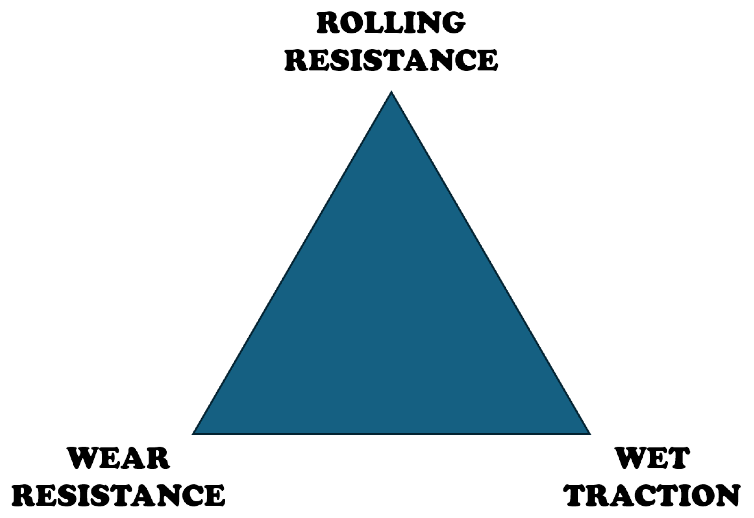
Figure 2.
Tire Force Profiles.
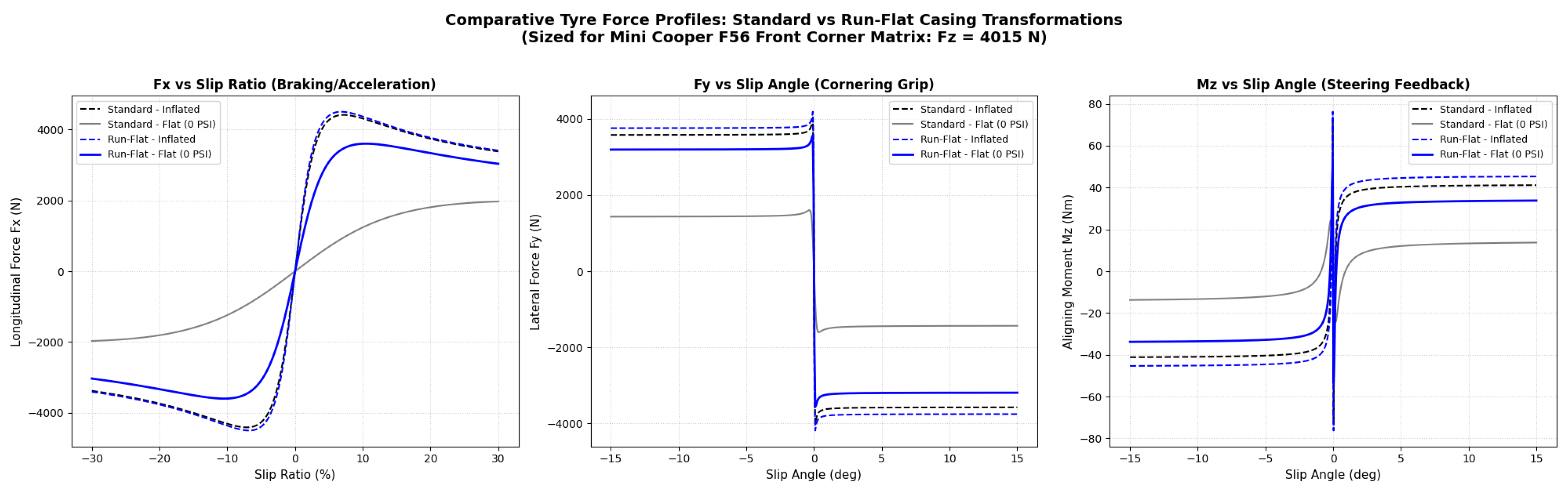
Figure 3.
Sensitivity analysis of Stanley controller gain.
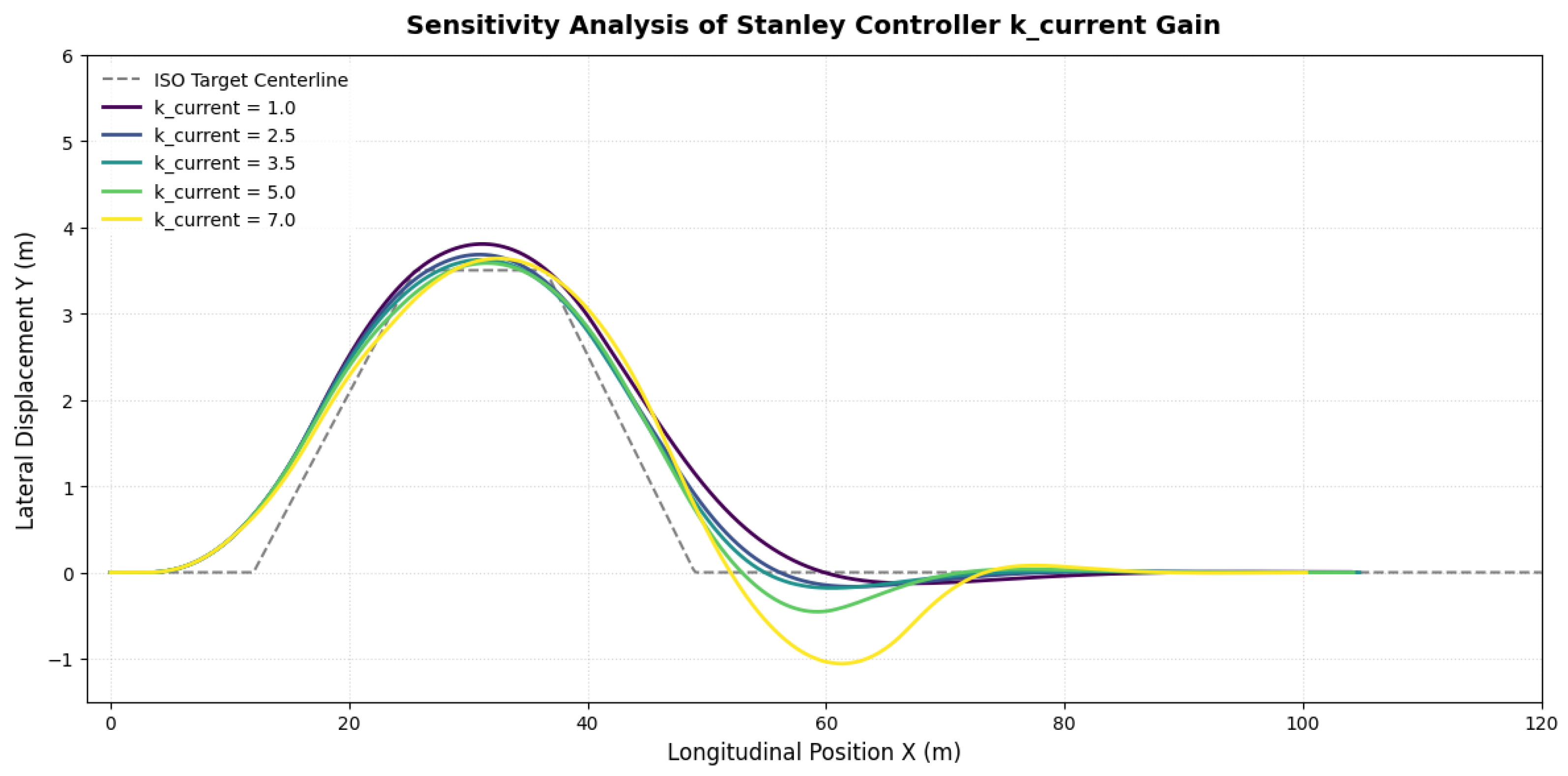
Figure 4.
ISO 3888-2 specifications (redrawn from [7]).
Figure 4.
ISO 3888-2 specifications (redrawn from [7]).
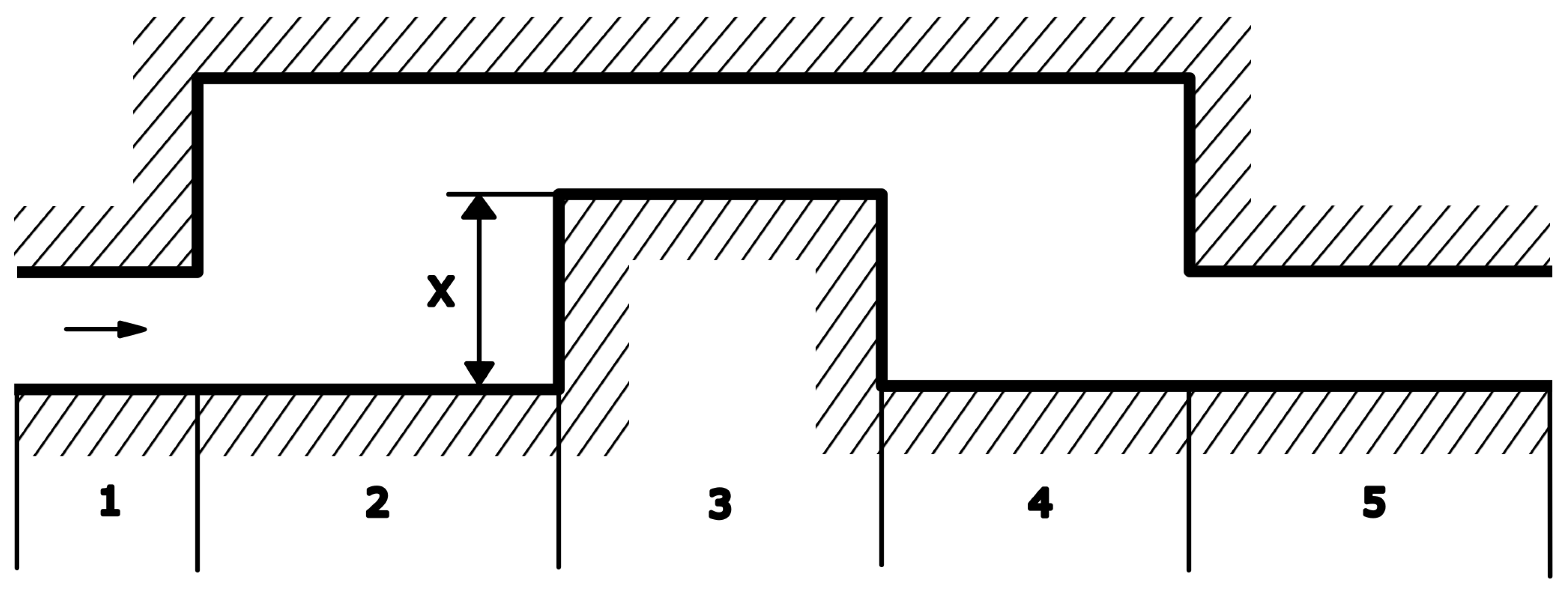
Figure 5.
Path Following and Roll Angle
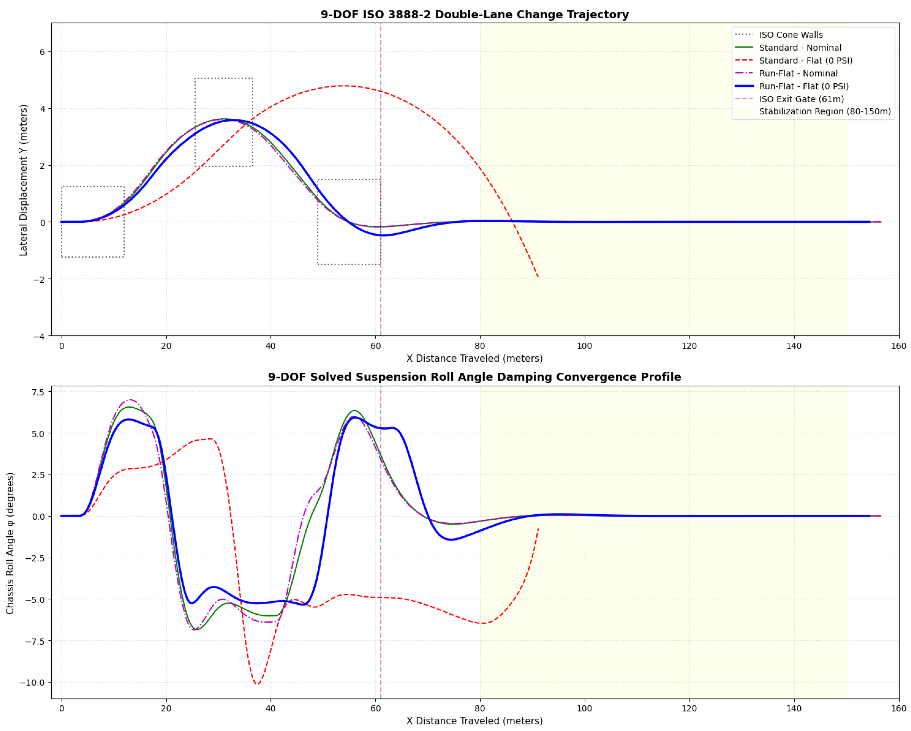
Figure 6.
(a) Front Left Puncture (b) Front Right Puncture.
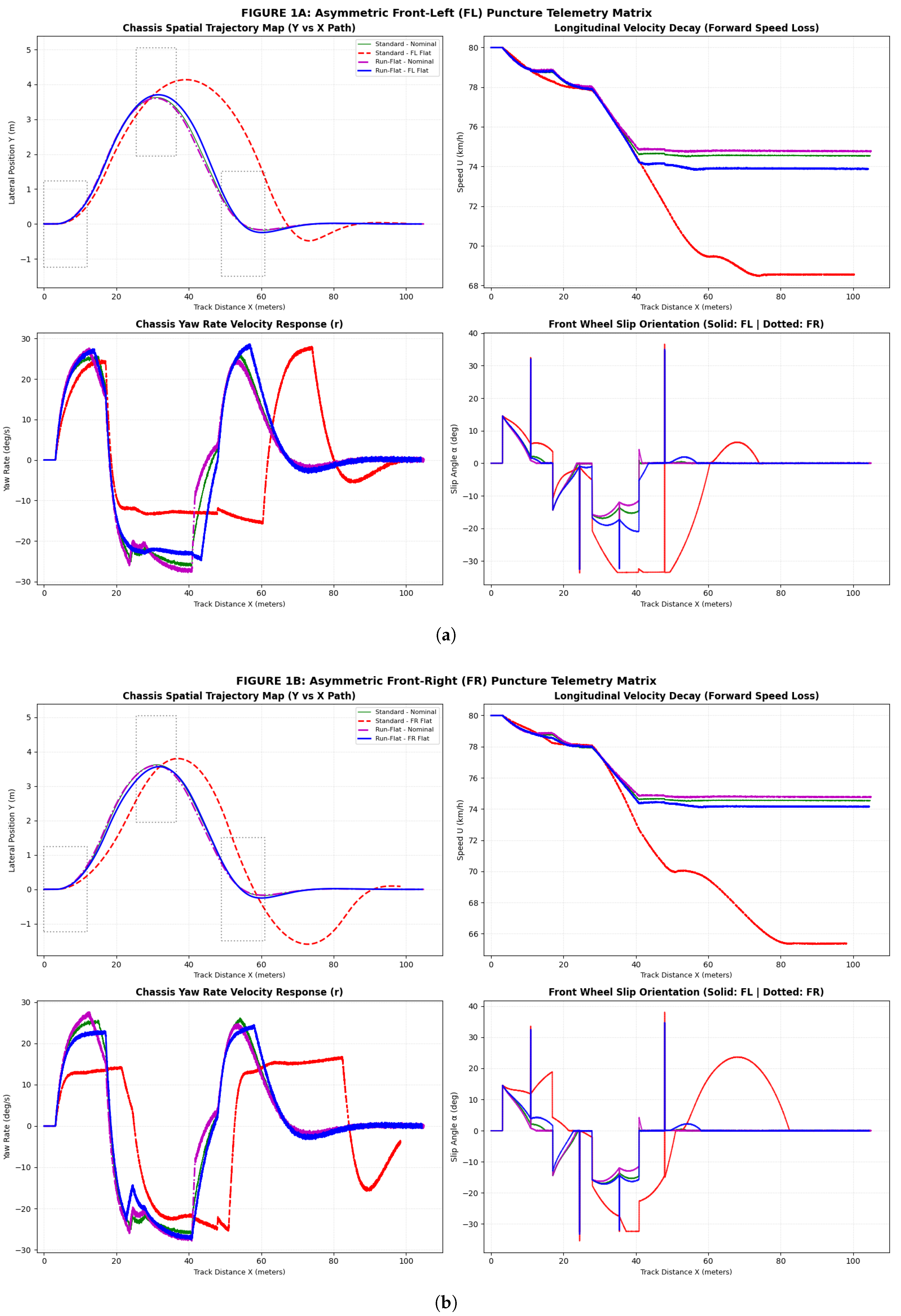
Figure 7.
Dual Front Tire Puncture.
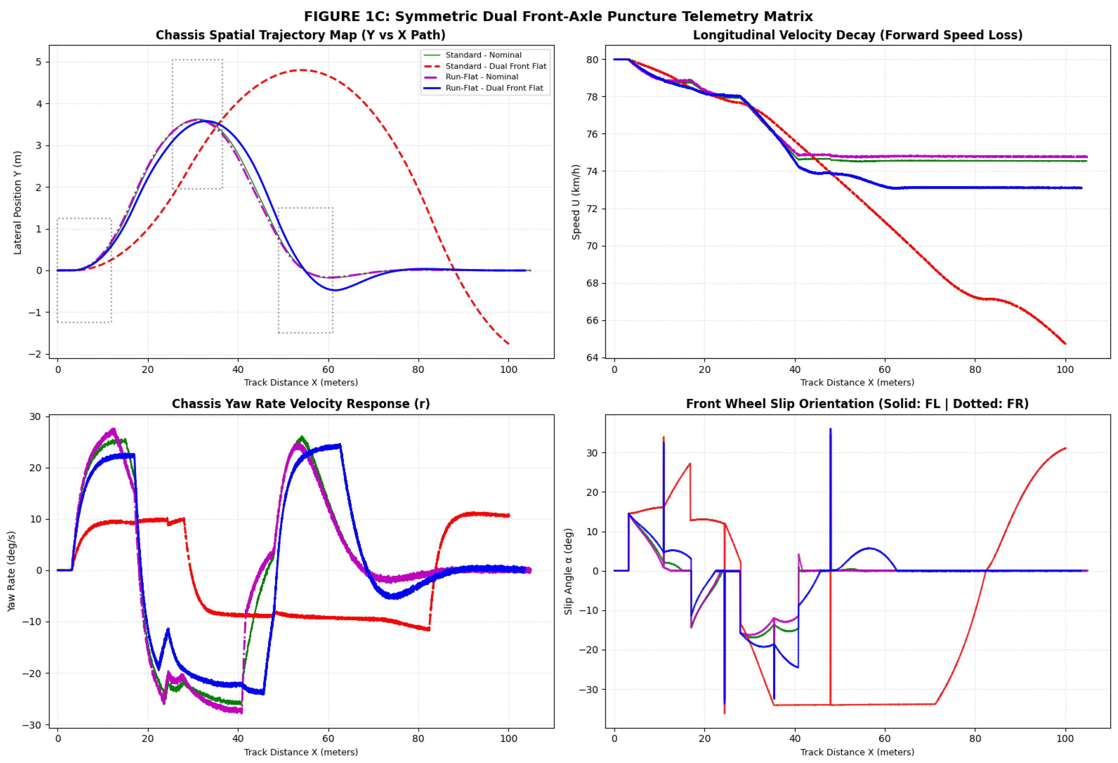

Table 1.
Comprehensive mapping of the literature catalog: Methodological approaches, key technical findings, and systemic integration frameworks.
Table 1.
Comprehensive mapping of the literature catalog: Methodological approaches, key technical findings, and systemic integration frameworks.
| Reference | Core Methodology | Key Technical Finding | Integration Into Present Work |
|---|---|---|---|
| Theme 1: Structural Rubber Composites, Sidewall Insert Rubber (SIR), and Hyperelastic FEA | |||
| Lv et al. (2023) | Non-linear FEA | Sidewall insert thickness ( mm) optimizes critical stress distribution matrices at zero inflation pressure. | Establishes the precise structural geometry baseline for the simulated SIR profile. |
| Zang et al. (2025) | Thermo-mechanical FEA | Deflated total footprint area expands by 223.8%, yet effective structural contact zone contracts by 47.3%. | Mechanistically explains the physical breakdown governing transient degradation. |
| Okan et al. (2020) | Material Synthesis | Replacing 5% of conventional carbon black with graphene nanofibers balances the tire “Magic Triangle” metrics. | Contextualizes advanced chemical design paths for optimizing structural tire compounds. |
| Testa et al. (2025) | Numerical Prototyping | Disjointed radial HeroBelt rim assemblies effectively isolate and dissipate extreme thermal run-flat friction fields. | Broadens the state-of-the-art summary toward secondary auxiliary wheel-supported fallback systems. |
| Theme 2: Analytical Tire Modeling, Slip Physics, and Magic Formula Formulations | |||
| Pacejka, H. (2005) | Semi-empirical Modeling | Derives normalized, non-linear coupled lateral and longitudinal tire-road force interactions under slip (). | Dictates the algebraic core used in Equation (1) to map transience force envelopes. |
| Mahajan, A.M. (2025) | Comparative MF Simulation | Deflated conventional tires yield tracking errors m compared to m preserved by SSRFT structures. | Corroborates the kinematic path deviation scale isolated in this closed-loop simulation. |
| Singh & Sivaramakrishnan (2023) | Extended Magic Formula | Real-time adaptive parameter fitting loops dynamically adjust compliance matrices during rapid pressure drops. | Links structural tire pressure failures with active differential slip feedback equations. |
| Guo et al. (2025) | Triaxial Grid Modeling | Combined severe braking vectors drive the locus of peak vertical contact stresses forward on the patch. | Aids the geometric interpretation of Kamm’s friction circle envelopes under combined slip. |
| Theme 3: Kinematic Path Planning, Trajectory Tracking, and Autonomous Controls | |||
| Nguyen et al. (2024) | Kinematic Path Optimization | Implements predictive multi-constraint routing logic during high-speed double-lane change (DLC) execution. | Mirrors and structurally informs the implementation of the primary Stanley trajectory loop. |
| Rajamani, R. (2006) | Active Safety Formulations | Explicitly maps cross-track tracking error bounds alongside operational geometric understeer indexes. | Legitimizes the choice of key performance indicators (KPIs) used to track vehicle control limits. |
| Theme 4: Classical Chassis Dynamics, Vehicle Testing, and Load Transfers | |||
| Heerwan et al. (2017) | Instrumented Field Trials | Maps speed-dependent lateral weight transfers and coupled inertial roll forces across varying velocities. | Formulates the exact empirical justification for choosing 80 km/h as the critical entry benchmark. |
| Gillespie, T. (1992) | Analytical Vehicle Handling | Defines fundamental analytical equations coupling transient roll, yaw, and lateral chassis accelerations. | Forms the multi-body chassis framework for Equations (2) and (4) regulating dynamic load shifts. |
| Milliken & M. (1995) | Race Car Vehicle Dynamics | Provides exhaustive models on tire lateral force generation, slip angles, and limit-handling balance. | Shapes the underlying state equations used to model the chassis’ non-linear transient properties. |
| Theme 5: ISO Standards, Co-Simulation Frameworks, and Stability Systems | |||
| ISO 3888-2 (2019) | Standard Specification | Outlines international closed-loop obstacle avoidance layout constraints for severe path testing (Moose Test). | Directs the precise layout geometry and entry limits for the simulated test route. |
| MathWorks (2023) | Co-Simulation Framework | Delivers standard MATLAB/Simulink blocks for vehicle blocks and virtual DLC environments. | Benchmarks the implementation of the 9-DOF plant model with the target environment. |
Table 2.
Physical parameters - [F56] MINI Cooper S.
| Category | Parameter | Symbol | Value | Unit |
|---|---|---|---|---|
| Mass and Inertia | Sprung Mass | 1150.0 | kg | |
| Unsprung Mass per Wheel | 40.0 | kg | ||
| Total Vehicle Mass | 1310.0 | kg | ||
| Roll Moment of Inertia | 400.0 | kg·m2 | ||
| Pitch Moment of Inertia | 1300.0 | kg·m2 | ||
| Yaw Moment of Inertia | 1400.0 | kg·m2 | ||
| Geometry and Dimensions | Distance from CG to Front Axle | 1.05 | m | |
| Distance from CG to Rear Axle | 1.445 | m | ||
| Wheelbase | 2.495 | m | ||
| Track Width | 1.485 | m | ||
| CG Height | 0.50 | m | ||
| Effective Tire Radius | 0.30 | m | ||
| Wheel Rotational Inertia | 0.9 | kg·m2 | ||
| Suspension Parameters | Front Suspension Spring Rate | 35,000.0 | N/m | |
| Rear Suspension Spring Rate | 32,000.0 | N/m | ||
| Front Damping Coefficient | 3,500.0 | N·s/m | ||
| Rear Damping Coefficient | 3,200.0 | N·s/m | ||
| Anti-Roll Bar Stiffness | 22,000.0 | N·m/rad |
Table 3.
ISO 3888-2 Track geometry and specifications
| Segment | Track Section | Longitudinal Range (X) | Geometry / Target Lateral Displacement (Y) |
|---|---|---|---|
| 1 | Entry Section | 0 to 12 m | Initial straight path with a constant lateral displacement of 0.0 m. |
| 2 | First Lane Change | 12 to 25.5 m | Smooth transition via a cosine curve up to a lateral displacement of 3.5 m (Dimension X in figure). |
| 3 | Stabilization Lane | 25.5 to 36.5 m | Straight section displaced from original line, maintaining a constant offset of 3.5 m. |
| 4 | Return to Original Lane | 36.5 to 49 m | Second cosine transition to bring the vehicle back down to 0.0 m. |
| 5 | Exit Section | Above 49 m | Final straight path stabilized at 0.0 m of lateral displacement. |
Table 4.
Quantitative Handling KPI Metrics Sized for the MINI Cooper S Platform ( N).
| Handling KPI Metric (at Exit Gate m) | Scenario A: | Scenario B: | Scenario C: | Scenario D: |
|---|---|---|---|---|
| Std Nominal | Std Flat | RFT Nominal | RFT Flat | |
| Run Set 1: Asymmetric Front-Left (FL) Puncture | ||||
| Peak Lateral Displacement () | 3.62 m | 4.13 m | 3.60 m | 3.70 m |
| Course Recovery Location (X) | 53.2 m | 66.2 m | 53.1 m | 53.4 m |
| Peak Steady-State Yaw Rate (r) | /s | /s | /s | /s |
| Terminal Exit Stability Status | Stable | Sliding | Stable | Stable |
| Max Driver Steering Input () | ||||
| Time Duration at Max Steer Lock | 0.020 s | 0.665 s | 0.021 s | 0.021 s |
| Terminal Exit Speed () | 74.6 km/h | 69.5 km/h | 74.8 km/h | 73.9 km/h |
| Max Peak Lateral Acceleration () | g | g | g | g |
| Run Set 2: Asymmetric Front-Right (FR) Puncture | ||||
| Peak Lateral Displacement () | 3.62 m | 3.80 m | 3.60 m | 3.57 m |
| Course Recovery Location (X) | 53.2 m | 57.3 m | 53.1 m | 53.1 m |
| Peak Steady-State Yaw Rate (r) | /s | /s | /s | /s |
| Terminal Exit Stability Status | Stable | Sliding | Stable | Stable |
| Max Driver Steering Input () | ||||
| Time Duration at Max Steer Lock | 0.020 s | 0.198 s | 0.021 s | 0.021 s |
| Terminal Exit Speed () | 74.6 km/h | 69.3 km/h | 74.8 km/h | 74.2 km/h |
| Max Peak Lateral Acceleration () | g | g | g | g |
| Run Set 3: Symmetric Dual Front-Axle Puncture | ||||
| Peak Lateral Displacement () | 3.62 m | 4.80 m | 3.60 m | 3.58 m |
| Course Recovery Location (X) | 53.2 m | 87.3 m | 53.1 m | 53.9 m |
| Peak Steady-State Yaw Rate (r) | /s | /s | /s | /s |
| Terminal Exit Stability Status | Stable | Sliding | Stable | Stable |
| Max Driver Steering Input () | ||||
| Time Duration at Max Steer Lock | 0.020 s | 1.240 s | 0.021 s | 0.114 s |
| Terminal Exit Speed () | 74.6 km/h | 61.2 km/h | 74.8 km/h | 72.8 km/h |
| Max Peak Lateral Acceleration () | g | g | g | g |
Disclaimer/Publisher’s Note: The statements, opinions and data contained in all publications are solely those of the individual author(s) and contributor(s) and not of MDPI and/or the editor(s). MDPI and/or the editor(s) disclaim responsibility for any injury to people or property resulting from any ideas, methods, instructions or products referred to in the content. |
© 2026 by the authors. Licensee MDPI, Basel, Switzerland. This article is an open access article distributed under the terms and conditions of the Creative Commons Attribution (CC BY) license (http://creativecommons.org/licenses/by/4.0/).
Copyright: This open access article is published under a Creative Commons CC BY 4.0 license, which permit the free download, distribution, and reuse, provided that the author and preprint are cited in any reuse.