

Submitted:
10 June 2026
Posted:
11 June 2026
You are already at the latest version
Abstract
This paper presents the design, construction, and experimental evaluation of a low-cost, portable solar tracking system for monitoring ultraviolet solar radiation in real time. It integrates a Raspberry Pi Zero 2W as the embedded control unit; an AS7331 spectral sensor to measure UVA, UVB, and UVC irradiance; two 270° servomotors to position the system toward the sun; a NEO-6M GPS module to geolocate the system; and a DS3231 real-time clock to synchronize the time. To enable autonomous outdoor operation, a multistage power supply architecture based on a solar panel, rechargeable battery, LM2596, and MP1584EN DC-DC regulators was implemented. The tracking algorithm uses astronomical equations to estimate solar azimuth and elevation and updates the sensor orientation during daylight hours. This allows the UV sensor to remain approximately normal to the incoming solar radiation. Experimental tests were conducted in Arequipa, Peru. The recorded data included UVA, UVB, and UVC irradiance; sensor temperature; geographic coordinates; time; and solar angles. The measured UV profiles exhibited the anticipated diurnal behavior: maximum values around solar noon, higher UVA levels than UVB levels, and minimal UVC levels due to atmospheric absorption. We compared the radiometric response with reference information from EarthKit, PVGIS 5.3, SAMPA, and a Davis Vantage Pro 2 weather station. We evaluated the solar positioning performance against Stellarium, NOAA, and the NREL Solar Position Algorithm. The prototype has an azimuth error of less than 0.009% and an elevation error of less than 0.4% compared to the NREL SPA, NOAA and Stellarium Systems. The results demonstrate that the proposed prototype provides a portable, customizable, and affordable platform for solar UV monitoring, educational instrumentation, and field-based solar resource assessment.
Keywords:
solar tracker
; UV spectrophotometer
; Raspberry Pi
; embedded system
; portable instrumentation
1. Introduction
Accurate monitoring of solar radiation is essential for assessing photovoltaic performance, characterizing solar resources, studying the atmosphere, monitoring the environment, and applying to public health. Ultraviolet (UV) radiation is of particular interest because its spectral components—UVA, UVB, and UVC—interact differently with the atmosphere and have distinct implications for biological exposure, material degradation, and solar energy applications. UVA and some UVB radiation reach the Earth’s surface, but UVC radiation is strongly absorbed by the atmosphere, especially by ozone. Therefore, it is expected to remain at very low levels under normal outdoor conditions. Therefore, monitoring the three UV bands separately is useful for identifying the spectral behavior of solar radiation and evaluating the performance of low-cost sensing systems under real environmental conditions [14,18,21,22]. Conventional solar radiation monitoring typically uses pyranometers, UV radiometers, spectroradiometers, or complete meteorological stations. While these instruments can provide reliable measurements, they are often restricted from use in educational laboratories, small research groups, and remote field campaigns due to their cost, maintenance requirements, and limited portability. This is particularly relevant in regions with high solar exposure, such as southern Peru, where continuous, spatially distributed measurements are needed to support solar energy studies and environmental monitoring. In this context, low-cost embedded instrumentation is an attractive alternative because it integrates sensors, microcontrollers, embedded computers, data storage, wireless communication, and an autonomous power supply into compact, customizable platforms [1,25].
Solar tracking systems have been widely investigated as a strategy to improve alignment between solar radiation and the receiving surface. In photovoltaic applications, two-axis tracking increases the amount of incident solar energy compared to fixed-plane configurations. In solarimetry and radiometric measurements, two-axis tracking improves the normal incidence condition between the sensor and the sun. Several studies have proposed solar trackers based on light-dependent resistors, microcontrollers, GPS modules, image processing, and astronomical algorithms [2–6,9–11]. However, many of these systems focus primarily on photovoltaic energy optimization and lack spectral UV measurement, autonomous time synchronization, geolocation, and local data acquisition capabilities in a single, portable instrument.
Calculating the Sun’s apparent position is a fundamental aspect of solar tracking. Solar azimuth and elevation can be estimated using astronomical relationships based on date, time, geographic coordinates, solar declination, hour angle, and zenith angle.[7,12]. These formulations are extensively used in solar energy engineering and have been implemented in high-precision tools, such as the Solar Position Algorithm developed by the National Renewable Energy Laboratory, as well as in astronomical and solar resource models [16,17]. Using astronomical positioning has advantages because it avoids dependence on optical feedback sensors, which can be affected by clouds, shadows, misalignment, and local reflections. Therefore, an embedded system capable of calculating the sun’s position in real time can provide a robust basis for autonomous solar tracking.[23,24]
Recent advances in compact spectral sensors have enabled the development of low-cost UV monitoring systems. The AS7331 is a digital UV sensor that can measure three spectral bands associated with UVA, UVB, and UVC radiation via an I2C interface. This makes it ideal for embedded applications requiring low power consumption, a compact size, and digital communication [15]. Previous studies on low-cost UV monitoring devices have demonstrated the feasibility of using compact commercial sensors to measure environmental solar radiation, while also highlighting the importance of spectral and angular responses, leveling, calibration, and comparison with reference data [28]. Consequently, integrating a UV spectral sensor with a solar tracking platform improves the incidence geometry and provides more consistent diurnal measurements than static sensor configurations.
Despite progress in solar tracking and low-cost environmental monitoring, portable systems combining dual-axis solar tracking, real-time UV spectral measurement, autonomous operation, geolocation, time synchronization, and experimental validation are still needed. Most low-cost solar trackers focus on energy capture, and most low-cost UV instruments are static and do not actively orient the sensor toward the sun. This work fills that gap by proposing an integrated embedded system that monitors UVA, UVB, and UVC irradiance in real time under solar tracking conditions.
This work primarily focuses on the design, construction, and experimental evaluation of a low-cost, portable, dual-axis solar tracking system for monitoring UV radiation. The prototype uses a Raspberry Pi Zero 2W as the main embedded controller and an AS7331 UV spectral sensor to measure UVA, UVB, and UVC. It also uses two 270° servomotors to position the system for azimuth and elevation, a NEO-6M GPS module to determine geographic location, and a DS3231 real-time clock to synchronize time. The system includes a multistage power supply architecture based on a solar panel, a rechargeable battery, and DC–DC converters (LM2596 and MP1584EN), which allow for autonomous operation in outdoor environments.
The system was tested through experimentation in Arequipa, Peru, where high levels of solar radiation make the development of portable solar monitoring instruments relevant for local research and educational applications. The following variables were measured: UVA, UVB, and UVC irradiance; AS7331 sensor temperature; date; time; geographic coordinates; and calculated solar azimuth and elevation. We compared the radiometric behavior with external reference information obtained from EarthKit, PVGIS 5.3, SAMPA, and a Davis Vantage Pro 2 weather station. We evaluated the positioning algorithm using Stellarium, NOAA, and the NREL Solar Position Algorithm. These results demonstrate the feasibility of using a low-cost embedded platform for solar tracking and UV monitoring. This provides a flexible tool for solar resource studies, environmental measurements, and educational instrumentation.
The remainder of this paper is organized as follows: Section 2 describes the hardware architecture of the proposed system, including the embedded controller, sensing modules, actuation mechanism, and power supply. Section 3 presents the construction procedure, electrical integration, software configuration, and operating instructions. Section 4 presents the experimental results obtained for UV radiation, sensor temperature, and solar tracking angles. Section 5 discusses how the system’s performance compares with reference models and positioning sources. Finally, Section 6 summarizes the main conclusions and potential improvements to the proposed prototype.
2. Hardware Description
This project aims to expand the capabilities of solar measurement systems through a portable, low-cost solution. Comparable commercial units exist in the range of several thousand dollars, but they generally lack portability, energy autonomy, and integrated spectral capabilities. Therefore, our system is not only 50 times cheaper than second-hand commercial units, but also allows for customization of its operation for various scientific and educational applications.
The hardware, as shown in Figure 1, consists of an integrated system that combines a two-axis solar tracker with a UV spectrophotometer. Key features include:
- Processing unit: Raspberry Pi Zero 2W with a 1GHz quad-core CPU, selected for its balance between processing power and low power consumption (2.5–3.0W).
- Sensing system: AS7331 UV sensor for three-band spectral measurement and temperature sensing, Ublox NEO-6M GPS module for geolocation, and DS3231 RTC module for precise timing.
- Actuation mechanism: Two LDX-227 digital servomotors with metal gears and a modified 270° range, providing sufficient torque (15 kg·cm to 17 kg·cm depending on the supply voltage) for operation in moderate wind conditions.
- Power supply system: Solar panel, LM2596 and MP1584EN regulators in a cascade configuration (Solar panel → Battery) and (Battery → System)
The main customizations made to the standard system include: (a) modification of the firmware to implement astronomical positioning algorithms, (b) implementation of a multistage voltage regulation system for autonomous operation, and (c) integration of multiple time synchronization sources.
The system implements standard astronomical equations for calculating solar position [8], determining solar azimuth and elevation based on date, time, and geographic location. These calculations are performed with an accuracy of ±0.01°. However, the effective mechanical accuracy of the prototype is limited by the PWM pulse resolution. Since the controller generates pulses in a range of 500 to 2500 μs to cover 270°, and the minimum resolution per step is 1 μs—which is equivalent to 0.135°—but considering the servomotor specifications, it has a resolution of 0.4°. Furthermore, considering the mechanical tolerances and the inherent backlash of the LDX-227 servomotors, a combined angular uncertainty of approximately ±0.5° is estimated. Additionally, according to the AS7331 datasheet, the sensor has a maximum angle of incidence of ±10°. Since the estimated maximum angular error for our system is ±0.5 degrees, this is sufficient for the sensor’s field of view, and the angular range of the servomotors allows for complete coverage of the sun’s path throughout all seasons of the year in tropical and subtropical latitudes.
An important feature of the system is its ability to operate in fully autonomous mode. The algorithm implements an energy management scheme that prioritizes different operating modes based on the availability of solar radiation and the battery charge status. During daylight hours (06:00–18:00), the system performs active tracking and data acquisition approximately every minute. At night, it enters low-power mode, maintaining only essential monitoring functions.
The system’s analog output provides real-time data on UV radiation across three spectral bands, sensor temperature, and tracker orientation. This data is stored locally in CSV format and can be transmitted remotely when connectivity is available.
Several factors must be considered, primarily the sun’s path; therefore, the expressions for solar position are based on standard astronomical models that estimate solar declination and the angles of altitude and azimuth as functions of the day of the year, latitude, and solar time. These relationships are used in solar position algorithms such as the NOAA Solar Position Algorithm and have been widely used in solar energy applications [9,12,16,17,23]. The solar declination is given by:
This is a classic approximation of solar declination where n = day of the year.
The solar elevation angle , which is the angle between the sun and the horizon, and the solar azimuth , which is the angle between the projection of the sun on the horizon and true north [10], are also determined by the following formulas:
Where:
- : is the zenith angle
- : observer’s latitude
- : solar declination
- : hour angle
- : solar time
In this case, the calculation for the summer solstice (≈ December 21, ): .
For the winter solstice (≈ June 21, ): .
Considering this information along with the latitude angle of in general, we have the following:
- Summer solstice (December): Azimuth: –, Maximum altitude:
- Winter solstice (June): Azimuth: –, Maximum altitude:
- Total range required: Azimuth: , Altitude:
Since the servomotors have a range of motion, this is sufficient to cover these ranges.
3. Construction Instructions
This section describes the steps required for the construction and implementation of the portable solar tracking system, including mechanical assembly, electronic integration, and software configuration.
3.1. Mechanical Assembly
The system’s structure was designed using MDF parts that were cut using laser technology. The aim was to create a lightweight structure that is easy to assemble. Once the parts are ready, assemble the main base and the side supports that hold the first servomotor for the azimuth axis.
Next, install the second servomotor, which is responsible for the elevation movement. The servomotors used include a set of metal parts that allow for different mounting configurations. In this case, one of these parts connects the servomotor shaft to the base on which the AS7331 spectral sensor is mounted.
During this stage, it is important not to secure the servomotor shafts fully, as the initial calibration will be performed later using a test program called servo_test.py, which positions the servomotors at a known reference point. Once this reference position has been reached, the shafts can be permanently secured using the corresponding screws. Finally, the base containing the AS7331 sensor is integrated with the structure of the second servomotor to complete the system’s mechanical assembly, as shown in Figure 2.
3.2. Electrical Installation
The electrical system is divided into two main subsystems: the power supply system and the communication system connecting the various electronic modules. The connections are based on the main connection diagram shown in Figure 3.
3.2.1. Power Supply System
Before integrating the voltage regulators into the system, the step-down DC-DC converters used in the circuit must be calibrated.
The first regulator, which is based on the LM2596 module, is used to regulate the voltage from the solar panel. For calibration, it is recommended that either a power supply close to 24 V is used, or the solar panel is connected to sufficient sunlight. Adjust the module’s potentiometer until a stable output of 15 V is obtained — a suitable value for charging the portable battery used in the system.
Next, adjust the second MP1584EN regulator to obtain a regulated output of 5 V using the 12 V from the portable battery as the input.
This adjustment must be performed before connecting the modules to the system, since these regulators are typically factory-set with an output close to the input voltage. Failure to calibrate the modules prior to connection can result in overvoltages that could damage sensitive components such as the Raspberry Pi Zero 2W.
Once the voltages have been regulated, the power supply system is integrated. The solar panel is connected to the LM2596 regulator input via a 2.1 mm DC jack connector, while the regulated 15 V output is connected to the portable battery charger input. Next, the 12 V output from the battery is connected to the MP1584EN regulator via another Jack DC connector, which reduces the voltage to 5 V.
The 5 V output powers the system’s main components, including the Raspberry Pi Zero 2W, GPS module, DS3231 real-time clock (RTC) module and servo motors. The AS7331 spectral sensor, meanwhile, is powered by the Raspberry Pi 3.3 V output to ensure compatibility with its I2C communication interface.
Male-female pin connectors were used to make system maintenance easier and allow for the simple replacement of components in the event of a failure.
3.2.2. Communication System
The Raspberry Pi Zero 2W serves as the system’s central control unit. It communicates with the NEO-6M GPS module via a UART interface at a baud rate of 9600, which allows for the retrieval of geographic position, date, and time. The AS7331 sensor and the DS3231 RTC module communicate with the Raspberry Pi using the I2C bus. They share the same bus but use different I2C addresses.
Finally, the servomotors are controlled via pulse width modulation (PWM) signals generated by the Raspberry Pi through its general-purpose input/output (GPIO) pins. Figure 4 shows the assembly of this section.
3.3. Software Configuration
The control system was developed using the Python programming language and operates on the Raspberry Pi Zero 2W.
Before running the main program, enable the I2C communication interface, used by the AS7331 sensor and RTC module. This can be done using the following command in the system terminal:
- > sudo raspi-config
In the configuration menu, go to the Interface Options section to enable the I2C interface. Next, install the required system libraries using the following command:
- > pip install pigpio astral pyserial adafruit-blinka iorodeo-as7331
These libraries allow you to control servomotors using PWM signals, calculate the sun’s position based on astronomical models, communicate with the GPS module via serial communication, and interact with the AS7331 spectral sensor.
To control the GPIO pins using the pigpio library, run the following command:
- > sudo pigpiod
The main program of the system allows you to modify the latitude and longitude settings using configurable variables within the code. This makes it easy to adapt the system to different geographic locations.
3.4. Automatic System Execution
The main program of the system allows you to modify the latitude and longitude settings using configurable variables within the code. This makes it easy to adapt the system to different geographic locations.
- > sudo nano /etc/systemd/system/myscript.service
This file specifies the path to the main script of the system. The service is enabled using the following commands:
- > sudo systemctl daemon-reload
- > sudo systemctl enable myscript.service
This ensures that the system starts automatically every time the Raspberry Pi is powered on. Figure 5 shows how to assemble the parts required to get the system up and running.
3.5. Operating and Startup Instructions
3.5.1. System Startup
To start the system, simply power on the Raspberry Pi Zero 2W with its power supply. The control software will run automatically during the operating system boot, so no additional user intervention is required.
During the boot process, the system synchronizes the time, giving priority to information obtained from the GPS module. If a valid GPS signal is unavailable, the system attempts to synchronize the time via the internet using the NTP protocol. If neither of these options is available, the DS3231 RTC module serves as a backup source.
Next, the system scans the servomotors to verify the tracking mechanism’s mechanical limits and confirm the actuators’ proper operation.
Before starting normal operation, the system must be oriented toward true north, as this direction corresponds to the 0° azimuth reference used by the solar positioning algorithm.
3.5.2. Normal Operation
The system operates automatically between 6:00 a.m. and 6:00 p.m., which corresponds to the daytime period. During this time, the program uses the Astral library to calculate the solar azimuth and elevation angles every minute based on astronomical equations.
Based on these calculations, the servomotors adjust the system’s orientation progressively to keep the sensor approximately perpendicular to the sun’s position.
At the same time, the AS7331 sensor measures ultraviolet radiation in the UVA, UVB, and UVC bands and records the sensor’s internal temperature. This data, along with the date, time, geographic coordinates, and solar angles, is stored in a CSV file for subsequent analysis using external tools.
The system operates autonomously throughout the day, periodically recording data and adjusting the sensor’s orientation according to the Sun’s apparent movement.
4. Results
This section may be divided by subheadings. It should provide a concise and precise description of the experimental results, their interpretation as well as the experimental conclusions that can be drawn.
4.1. Ultraviolet Radiation (UVA, UVB, UVC)
Measurements of ultraviolet radiation exhibit consistent diurnal behavior: low values during the early morning, gradual increase toward solar noon, and decrease during the afternoon.
The results show that UVA radiation has the highest values, followed by UVB. Meanwhile, the UVC component remains at minimal levels, consistent with strong atmospheric absorption in this band. This behavior follows the characteristic bell-shaped distribution reported by SENAMHI (Figure 6). Various irradiance tools were used to corroborate the shape of the curves and the magnitude of the measurements: EarthKit (an open-source Python library) was used to obtain reanalysis data (Figure 7), PVGIS 5.3 was used to generate historical time series (Figure 8), and NREL’s SAMPA estimator was used to obtain the data shown in Figure 9. This multi-source comparison validates the accuracy of the obtained data.
A Davis Vantage Pro 2 weather station, which includes a global solar irradiance sensor (Figure 10), was used to obtain experimental measurements. Note that this station records the global component, not the direct component, because it lacks a solar tracking system. However, it allows for the validation of data from previous sources and serves as a reference for calibrating and configuring the AS7331 sensor.
Finally, Figure 11, Figure 12 and Figure 13 present the averaged results for the UVA, UVB, and UVC bands, respectively. Unlike conventional static measurements, these figures show a more pronounced bell-shaped profile due to the direct and normal incidence of radiation on the sensor thanks to the solar tracking system. The data also underwent post-processing to ensure the integrity of the results by filtering out 5 to 8 anomalous daily measurements that did not correspond to the expected radiometric profile.
4.2. Measured Temperature
The daily thermal profile exhibits distinctive behavior influenced by thermal inertia. This causes minimum temperatures to occur at the start of the day, with higher values occurring at the end of the cycle than at the beginning. Despite the symmetry in solar elevation relative to noon, the thermal response is not identical due to this delay. However, the sensor’s direct exposure allows it to capture more dynamic variations, which are particularly noticeable during solar noon. Previous studies have modeled this phenomenon using diurnal functions that incorporate a time lag in the thermal maximum. This maximum typically occurs between two and four hours after peak irradiance, depending on local conditions and environment [26,27]. The thermal behavior recorded in this study is presented in Figure 14.
4.3. Solar Tracking: Azimuth and Elevation
The calculated and recorded solar azimuth and elevation angles demonstrate the anticipated behavior given the system’s geographic location in Arequipa, Peru. Figure 15 illustrates this behavior: the azimuth shows a monotonic variation throughout the day, while the elevation exhibits a bell-shaped curve with a maximum around solar noon.
The correspondence between the calculated angles and the movement of the servomotors confirms the correct implementation of the solar tracking algorithm and the proper orientation of the system during operation.
4.4. Comparison with Different Positioning Sources
To validate the accuracy of the solar tracking algorithm, we compared the azimuth and elevation angles calculated by the system with the values obtained using Stellarium, astronomical software that employs high-precision models to simulate the Sun’s position.
For this comparison, Stellarium was configured with the geographic location of Arequipa, Peru. The same dates and times recorded in the system’s data file (Figure 16) were used. The solar azimuth and elevation values obtained from Stellarium (Figure 17) were compared with the values calculated by the program running on the Raspberry Pi Zero 2W.
The theoretical coordinates of the Sun were obtained using the Stellarium software: an azimuth of (approximately ) and an elevation of (approximately ). To validate the performance of the prototype within a high-precision framework, these data were compared with the SPA (Solar Position algorithm) from the National Renewable Energy Laboratory (NREL), which provides an uncertainty of and can generate data in CSV format. Additionally, NOAA data were used, and radiometric validation was performed using EarthKit, an open-source library from the ECMWF (European Centre for Medium-Range Weather Forecasts) that provides access to ERA5-Land atmospheric reanalysis data. This multi-layered approach ensures that the angular position is compared against international meteorological standards, as shown in Table 1.
It is important to note that discrepancies between the experimental data and the NREL SPA reference are influenced by the sampling interval. While the reference algorithm provides values in whole minutes, the prototype has an operational latency of 22 seconds and records information accordingly. However, the prototype’s internal control system compensates for this time lag by performing kinematic calculations at the exact moment of capture. Figure 17 shows the comparison with Stellarium, which uses second-level precision, unlike Table 1, which uses values in minutes. Despite the ability of other sources, such as NOAA, to process data with second-level resolution, we chose to maintain the NREL SPA as the primary reference due to its international standard.
To evaluate the system’s accuracy, three strategic sampling intervals were defined over a period of five consecutive days: morning (8:15 a.m.), solar noon (12:30 p.m.), and afternoon (4:42 p.m.). A percentage error analysis was performed to quantify the prototype’s accuracy by comparing the five-day averages of experimental measurements against three reference sources: NREL, SPA, NOAA, and Stellarium. As shown in Percentage Error Table 4, there are deviations on the azimuth and elevation axes.

Table 2.
Comparison of error with different sources for a random point.
| Percentage Error | NREL SPA | NOAA | Stellarium |
|---|---|---|---|
| Error for Azimut point 1 | |||
| Error for Azimut point 2 | |||
| Error for Azimut point 3 | |||
| Error for Elevation point 1 | |||
| Error for Elevation point 2 | |||
| Error for Elevation point 3 |
5. Discussion
To evaluate the system’s accuracy, three strategic sampling intervals were defined over a period of five consecutive days: morning (8:15 a.m.), solar noon (12:30 p.m.), and afternoon (4:42 p.m.). A percentage error analysis was performed to quantify the prototype’s accuracy by comparing the five-day averages of experimental measurements against three reference sources: NREL, SPA, NOAA, and Stellarium. As shown in Percentage Error Table 4, there are deviations on the azimuth and elevation axes.
Author Contributions
Conceptualization: Walter Daniel León Salas, Miguel Vizcardo Cornejo, José Luis Solís Véliz, and Mauricio Postigo Málaga; Methodology: José Luis Solís Véliz and Yefri Calla Zapana; Software: Yefri Calla Zapana and Carlos Puma Apaza; Validation: Yefri Calla Zapana and Carlos Puma Apaza; Formal Analysis: Walter Daniel León Salas, Miguel Vizcardo Cornejo, José Luis Solís Véliz, and Mauricio Postigo Málaga; Research: Yefri Calla Zapana and Carlos Puma Apaza; Resources: Miguel Vizcardo Cornejo; Data Curation: Yefri Calla Zapana; Writing—Original Draft: Yefri Calla Zapana; Writing—Revision and Editing: Yefri Calla Zapana; Visualization: Yefri Calla Zapana; Supervision: Walter Daniel León Salas, Miguel Vizcardo Cornejo, José Luis Solís Véliz, and Mauricio Postigo Málaga; Project Management: Miguel Vizcardo Cornejo Funding Acquisition: Miguel Vizcardo Cornejo. All authors have read and approved the published version of the manuscript.
Funding
This research was funded by Prociencia Concytec, grant number PE501081990-2023, and the article processing fee (APC) was also funded by Prociencia Concytec.
Institutional Review Board Statement
The study was conducted in accordance with the Declaration of Helsinki.
Informed Consent Statement
Not applicable.
Data Availability Statement
The data will be available once the article is published and by writing an email to the authors.
Acknowledgments
The authors thank Prociencia Concytec for the funding and the National University of San Agustín of Arequipa for the facilities provided to carry out this research.
Conflicts of Interest
The authors declare no conflicts of interest.
References
- Conde, L.A.; et al. Evaluación del rendimiento y caracterización de diferentes tecnologías fotovoltaicas en las condiciones climáticas costeras y desérticas de Lima, Perú. Proceedings of the ISES Solar World Congress 2019 and the IEA SHC International Conference on Solar Heating and Cooling for Buildings and Industry 2019 2020, 773–783.
- Sucharitha, P.; et al. Review and implementation of a sun position tracker with two-axis control. IOP Conference Series: Materials Science and Engineering 2020, 981(4), 042073.
- Hernández Velázquez, J. Diseño y construcción de un seguidor solar para aplicaciones en solarimetría. Revista Iberoamericana de Producción Académica y Gestión Educativa 2018.
- Calderón Naranjo, C.P. Diseño y simulación de un seguidor solar para mejorar el rendimiento de paneles solares portátiles; Tesis de pregrado, Universidad Politécnica Salesiana: Cuenca, Ecuador, 2024.
- Cazani Ramos, A.A.; Nieto Nieto, P.M. Diseño de un sistema fotovoltaico de 200W con seguimiento solar de dos ejes para maximizar la eficiencia energética; Tesis de pregrado, Universidad Peruana de Ciencias Aplicadas: Lima, Perú, 2024.
- Muñoz Castro, J.D. Sistema autónomo de seguimiento solar asociado a un GPS; Tesis de pregrado, Benemérita Universidad Autónoma de Puebla: Puebla, México, 2024.
- Blanco-Muriel, M.; et al. Computing the solar vector. Solar Energy 2001, 70(5), 431–441. [CrossRef]
- Gualoto Cachago, J.A.; Potosí Díaz, R.A. Desarrollo de un seguidor solar automatizado usando un sistema embebido y algoritmo de posicionamiento solar (SPA); Universidad Politécnica Salesiana, 2022.
- Stinia, H.; et al. The Light-On Project: Design and construction of a solar tracking system through image processing. IOP Conference Series: Earth and Environmental Science 2021, 642(1), 012009.
- Suryanto, A.; et al. Two-axis solar tracking system based on Raspberry Pi images. IOP Conference Series: Earth and Environmental Science 2021, 700(1), 012016.
- Catota Sánchez, A.V.; Simbaña Simbaña, J.E. Diseño de un colector térmico mediante concentración parabólica de seguimiento solar en dos ejes; Tesis de pregrado, Universidad Politécnica Salesiana: Quito, Ecuador, 2020.
- Reda, I.; Andreas, A. Solar position algorithm for solar radiation applications. Solar Energy 2004, 76(5), 577–589. [CrossRef]
- Kalogirou, S.A. Solar Energy Engineering: Processes and Systems, 2nd ed.; Academic Press, 2014.
- Alfaro Lozano, L.; Llacza Rodríguez, A.; Sánchez Ccoyllo, O. Pronóstico con cobertura nacional del índice de radiación solar ultravioleta; Nota Técnica N.° 002-2016; Servicio Nacional de Meteorología e Hidrología del Perú (SENAMHI): Lima, Perú, 2016.
- ams-OSRAM. AS7331: UV-A/B/C Spectral Sensor Datasheet; 2022.
- Reda, I.; Andreas, A. Solar Position Algorithm for Solar Radiation Applications; NREL/TP-560-34302; National Renewable Energy Laboratory, 2008.
- Meeus, J. Astronomical Algorithms; Willmann-Bell, 1991.
- Iqbal, M. An Introduction to Solar Radiation; Academic Press, 2012.
- Duffie, J.A.; Beckman, W.A. Solar Engineering of Thermal Processes, 4th ed.; John Wiley & Sons, 2013. [CrossRef]
- Lorenzo, E. Energy collected and delivered by PV modules. In Handbook of Photovoltaic Science and Engineering; Wiley, 2011; pp. 905–970.
- Kasten, F.; Young, A.T. Revised optical air mass tables and approximation formula. Applied Optics 1989, 28(22), 4735–4738. [CrossRef]
- Gueymard, C.A. The sun’s total and spectral irradiance for solar energy applications and solar radiation models. Solar Energy 2004, 76(4), 423–453. [CrossRef]
- Michalsky, J.J. The astronomical almanac’s algorithm for approximate solar position (1950–2050). Solar Energy 1988, 40(3), 227–235. [CrossRef]
- Blanco-Muriel, M.; Alarcón-Padilla, D.C.; López-Moratalla, T.; Lara-Coira, M. Computing the solar vector. Solar Energy 2001, 70(5), 431–441. [CrossRef]
- Sengupta, M.; Habte, A.; Gueymard, C.; Wilbert, S.; Renné, D. Best Practices Handbook for the Collection and Use of Solar Resource Data for Solar Energy Applications; NREL/TP-5D00-68886; National Renewable Energy Laboratory, 2017.
- García Cueto, O.R. Análisis de la variación diurna de la temperatura del aire y su relación con la radiación solar; Tesis de maestría, Universidad Nacional Autónoma de México: Ciudad de México, México, 2012.
- Felber, R.; Stoeckli, S.; Calanca, P. Generic calibration of a simple model of diurnal temperature variations for spatial analysis of accumulated degree-days. International Journal of Biometeorology 2018, 62(4), 621–630. [CrossRef]
- Serrano, A.; Marín, M.J.; Antón, M.; Cancillo, M.L.; Vilaplana, J.M. Development of a Low-Cost Device for Measuring Ultraviolet Solar Radiation. Frontiers in Environmental Science 2022, 9, 737875.
Figure 1.
Diagram of the portable solar tracker showing the main components
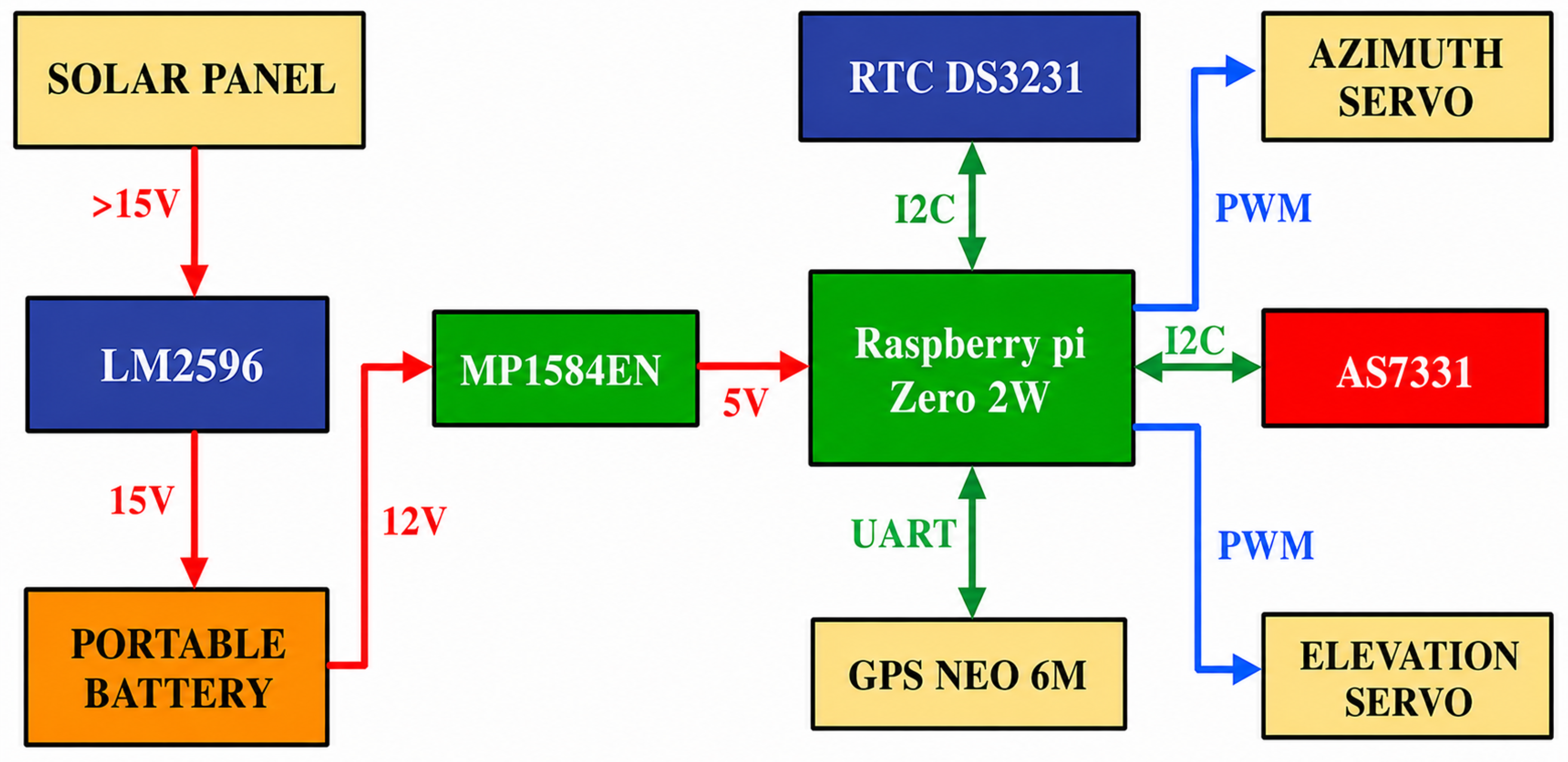
Figure 2.
Main integration of servos and cut parts
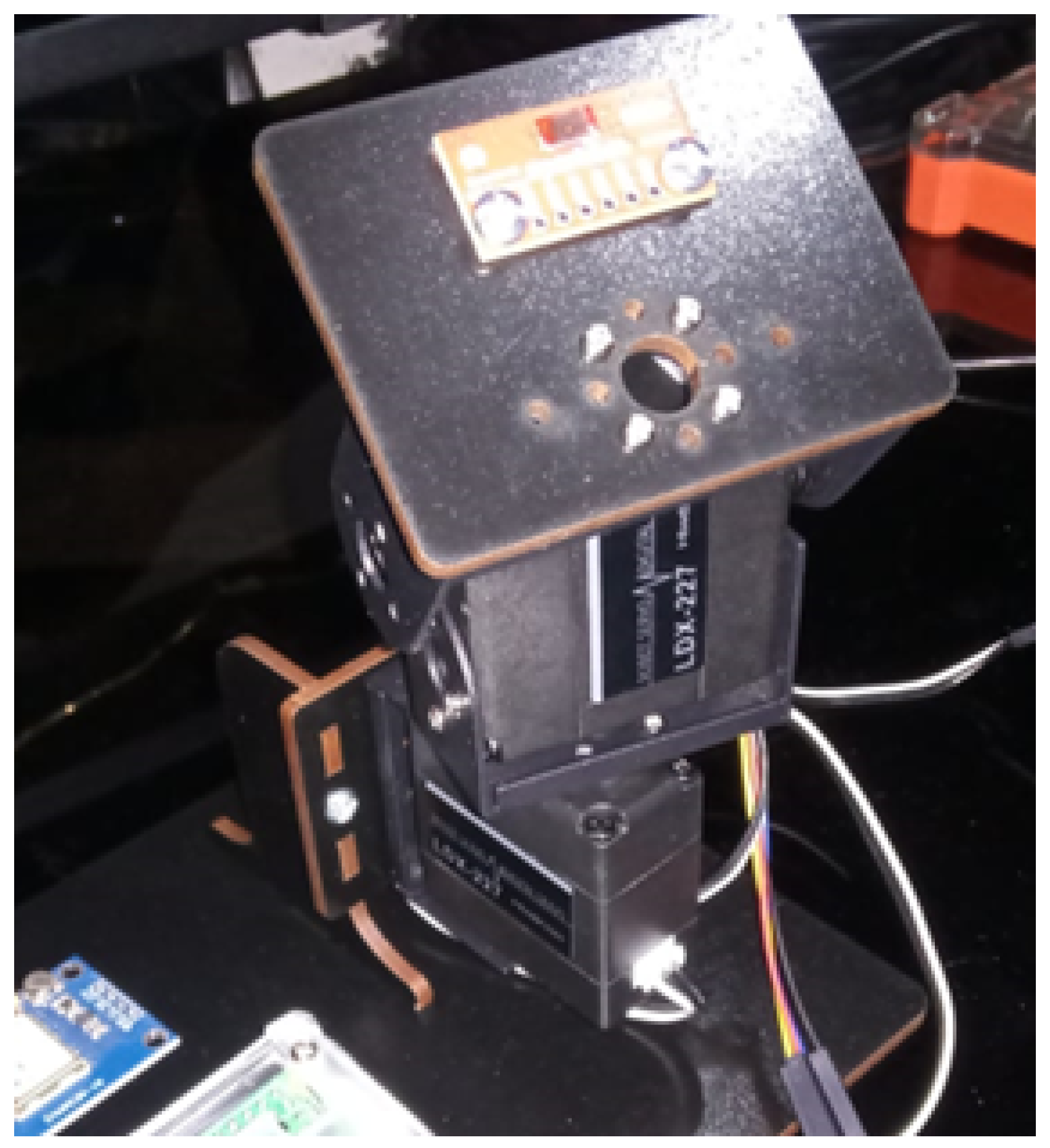
Figure 3.
Main connection diagram
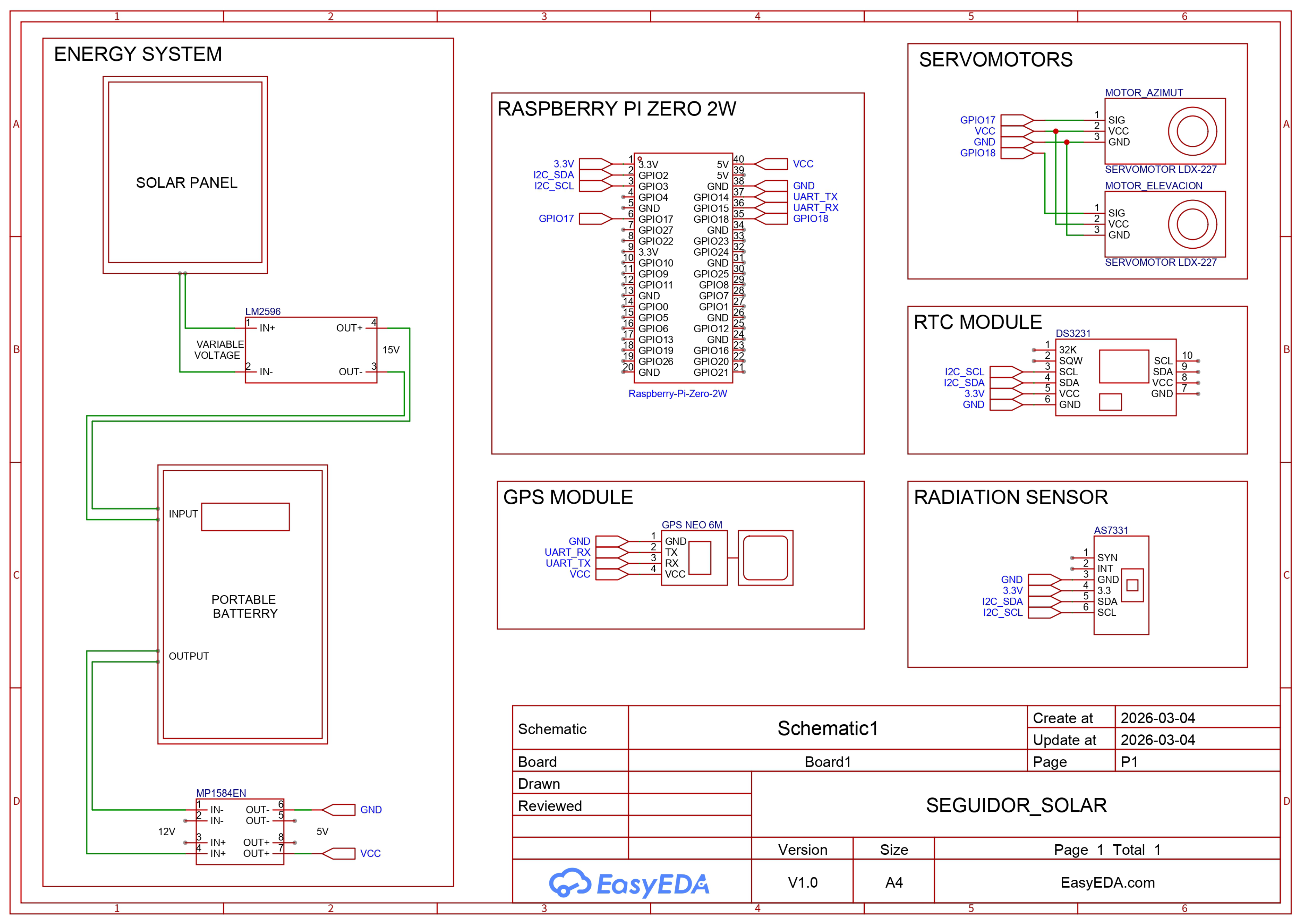
Figure 4.
Integration of electronic components
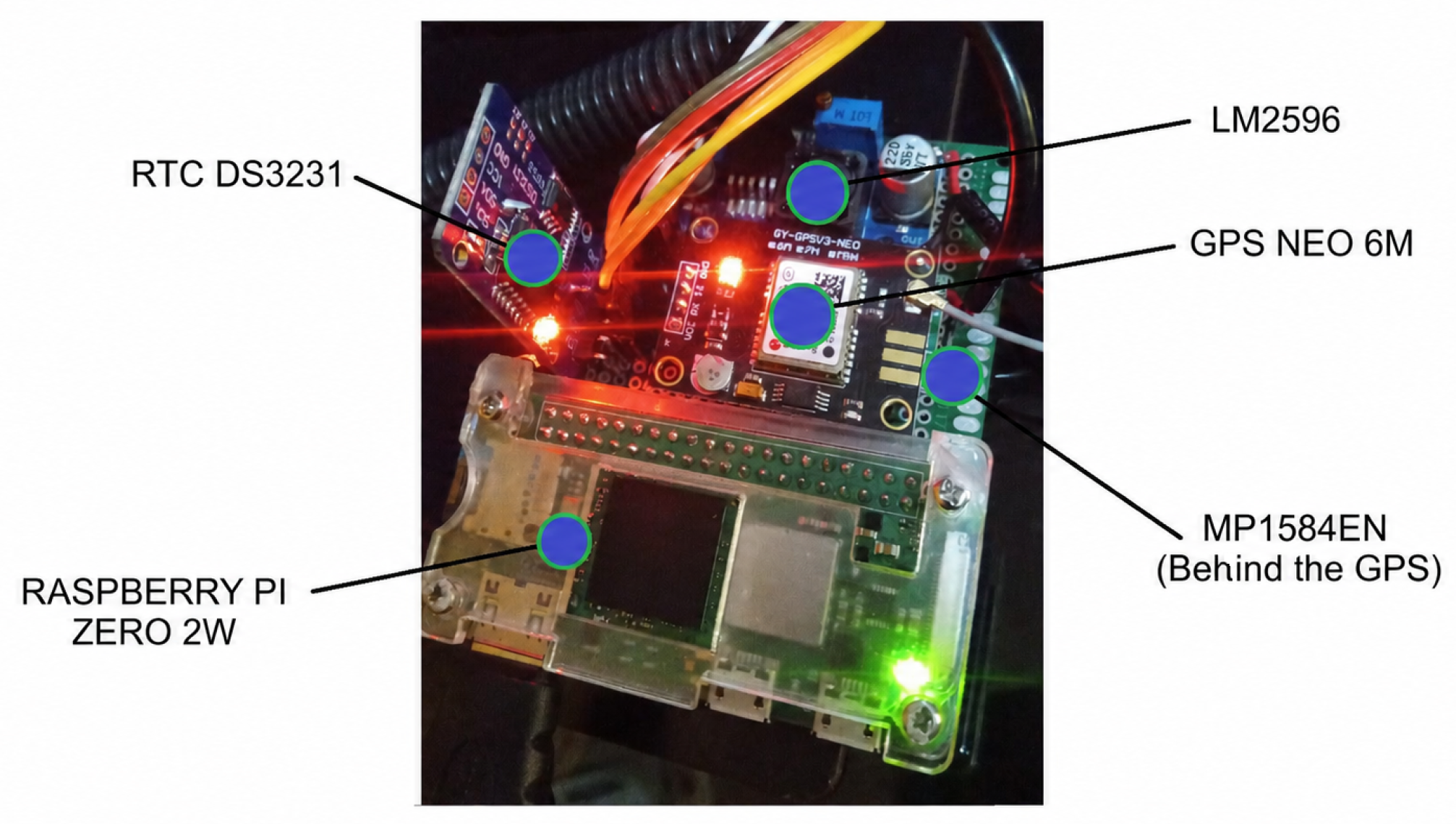
Figure 5.
System assembled for initial testing
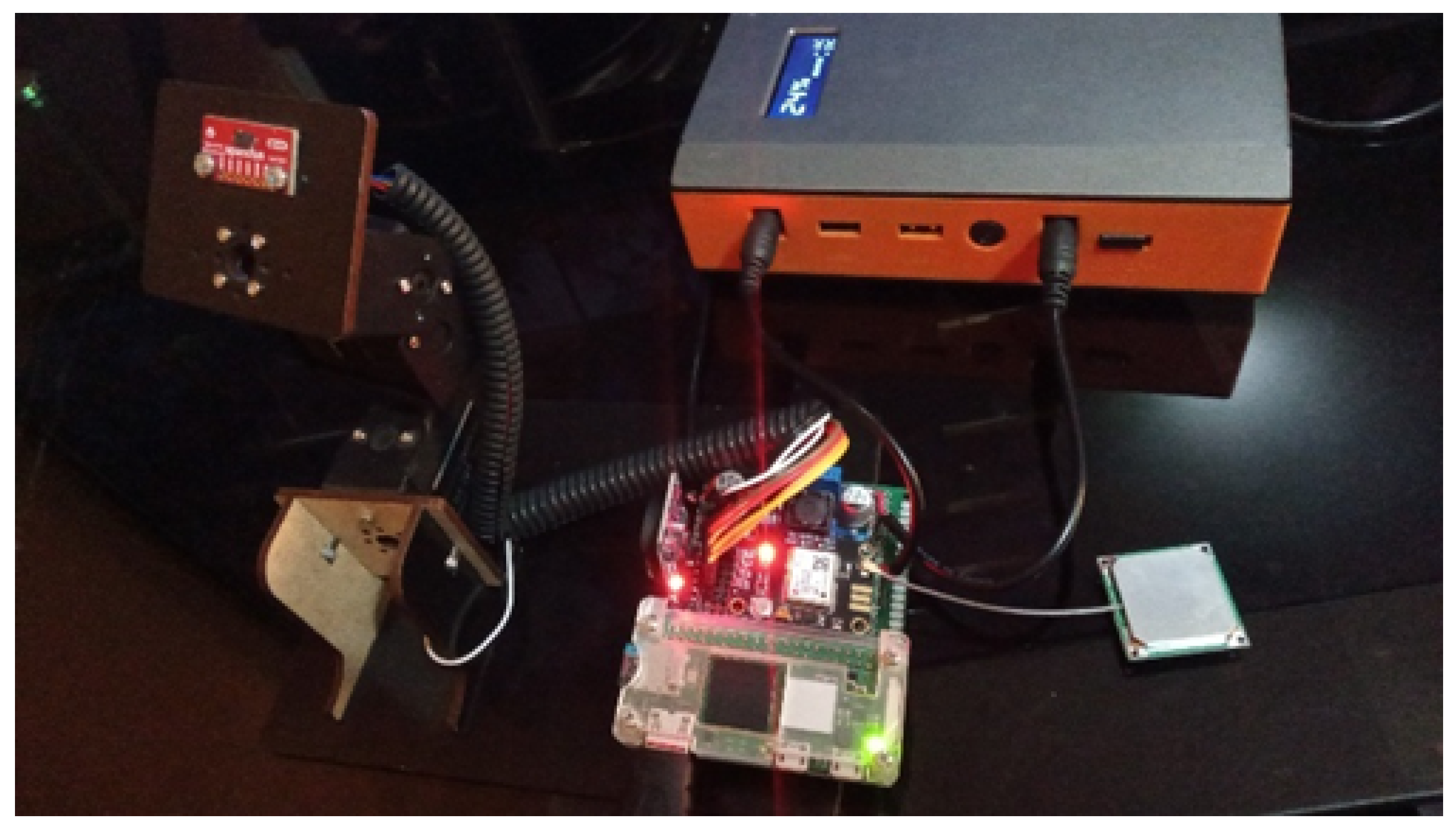
Figure 6.
UVI estimation using the Allart, Madronich formulas and the TUV model [14]
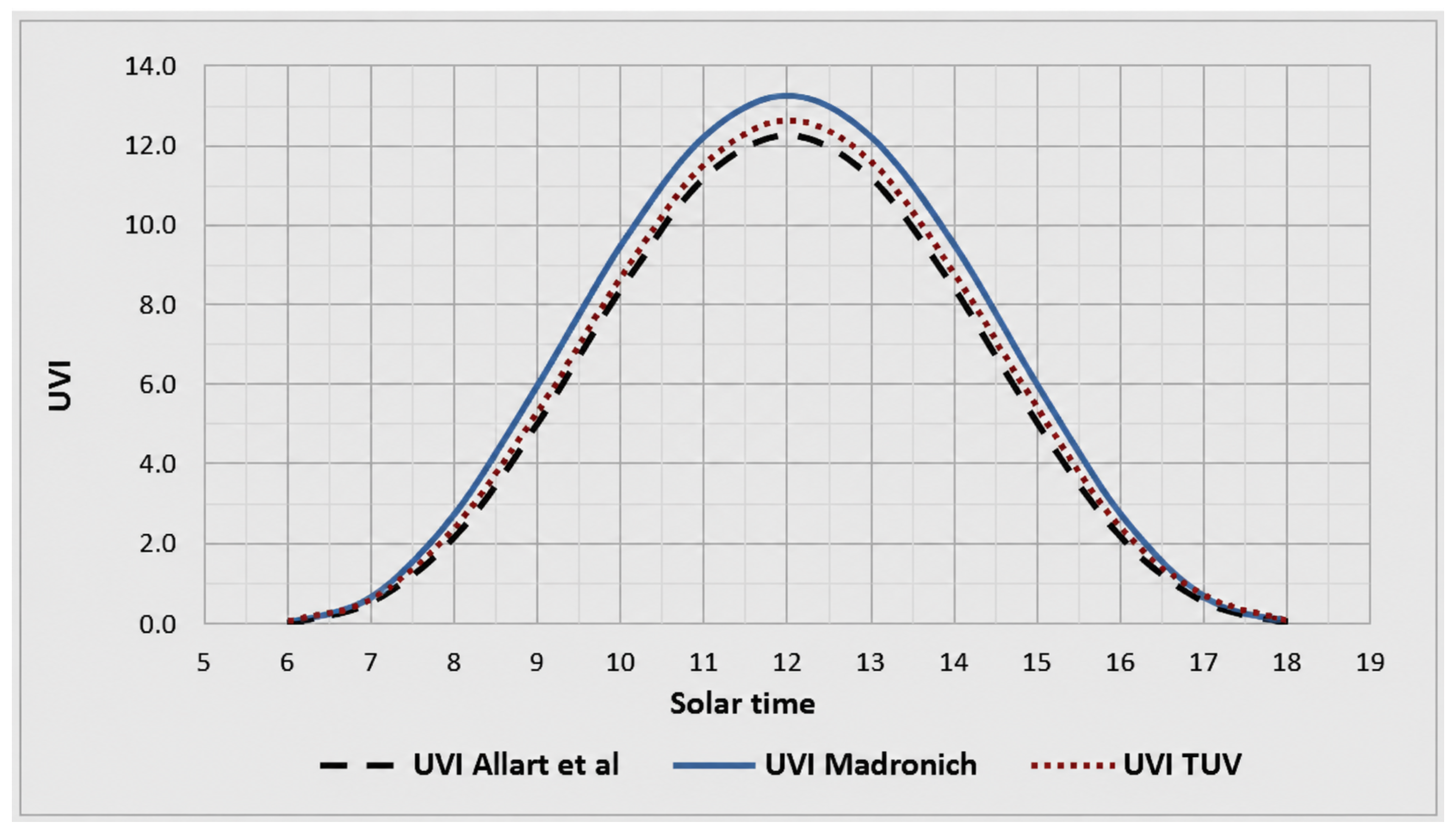
Figure 7.
Irradiance and temperature obtained with Earthkit
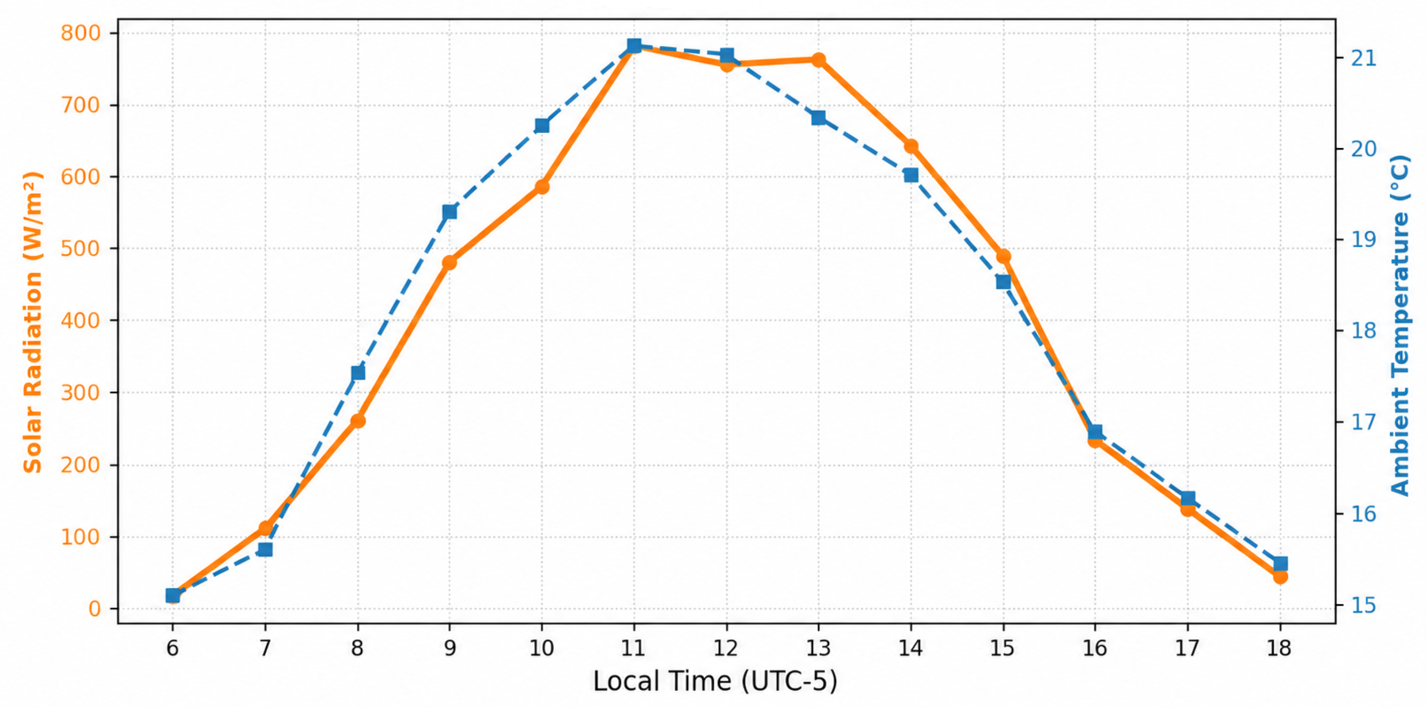
Figure 8.
Direct and global irradiance obtained with PVGIS
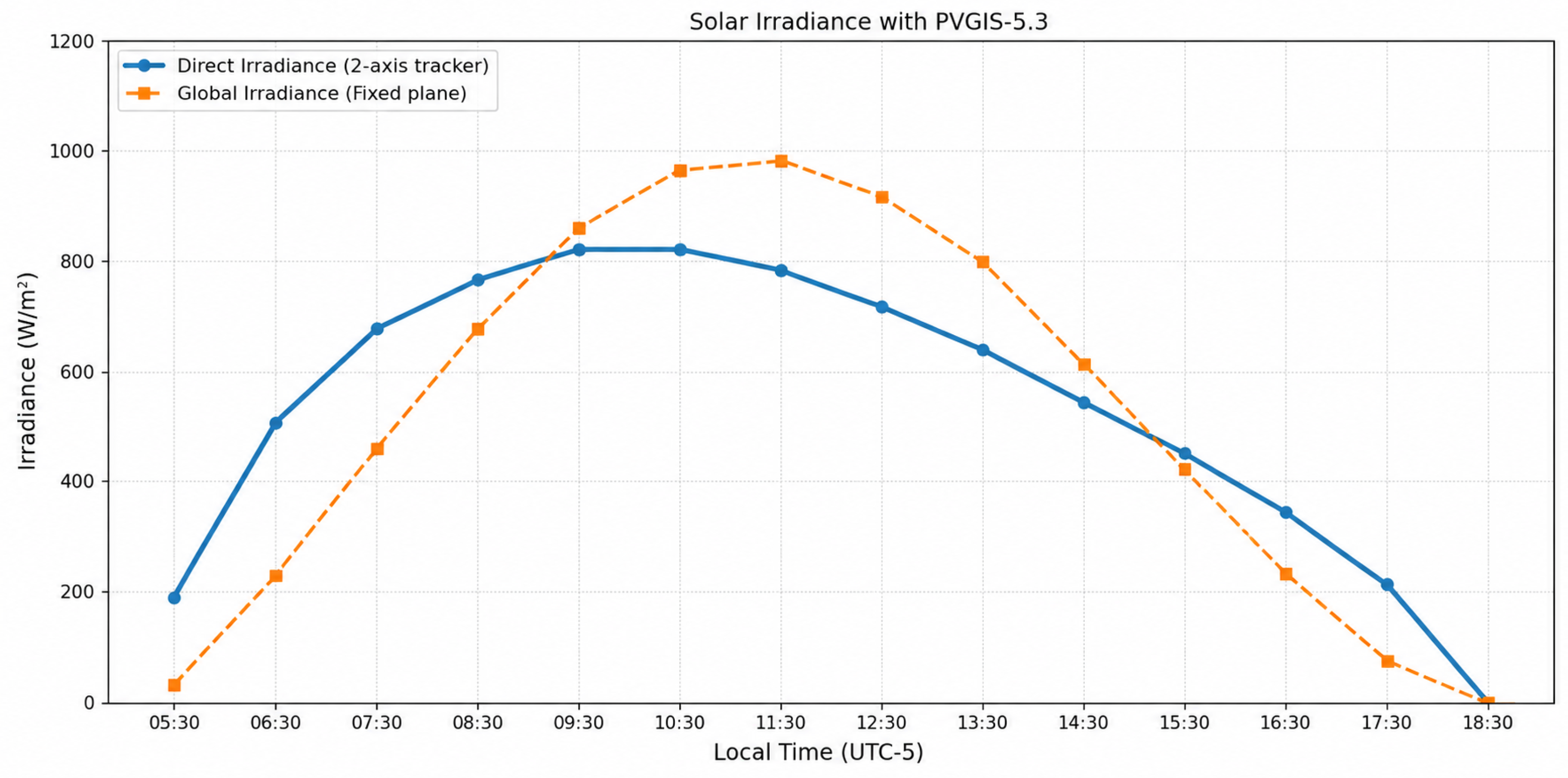
Figure 9.
Irradiance obtained using SAMPA
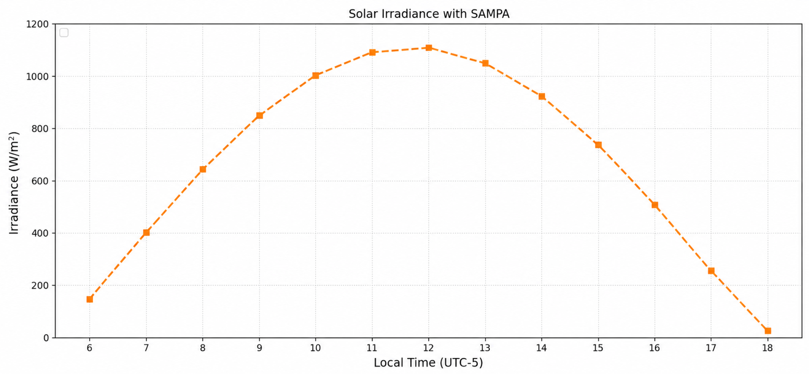
Figure 10.
Davis Vantage Pro 2 weather station used
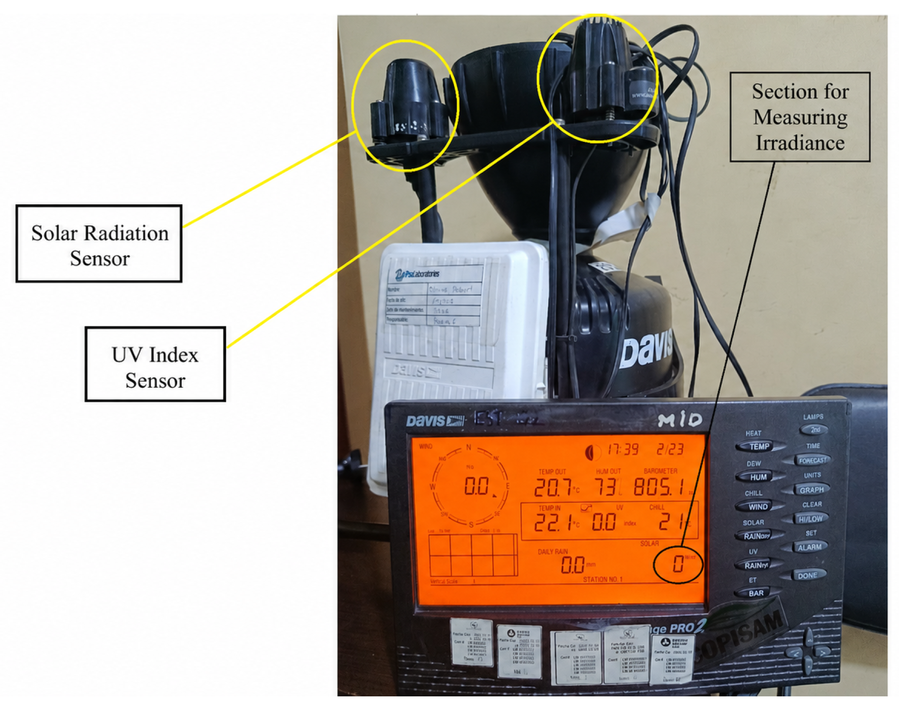
Figure 11.
UVA radiation during the time period
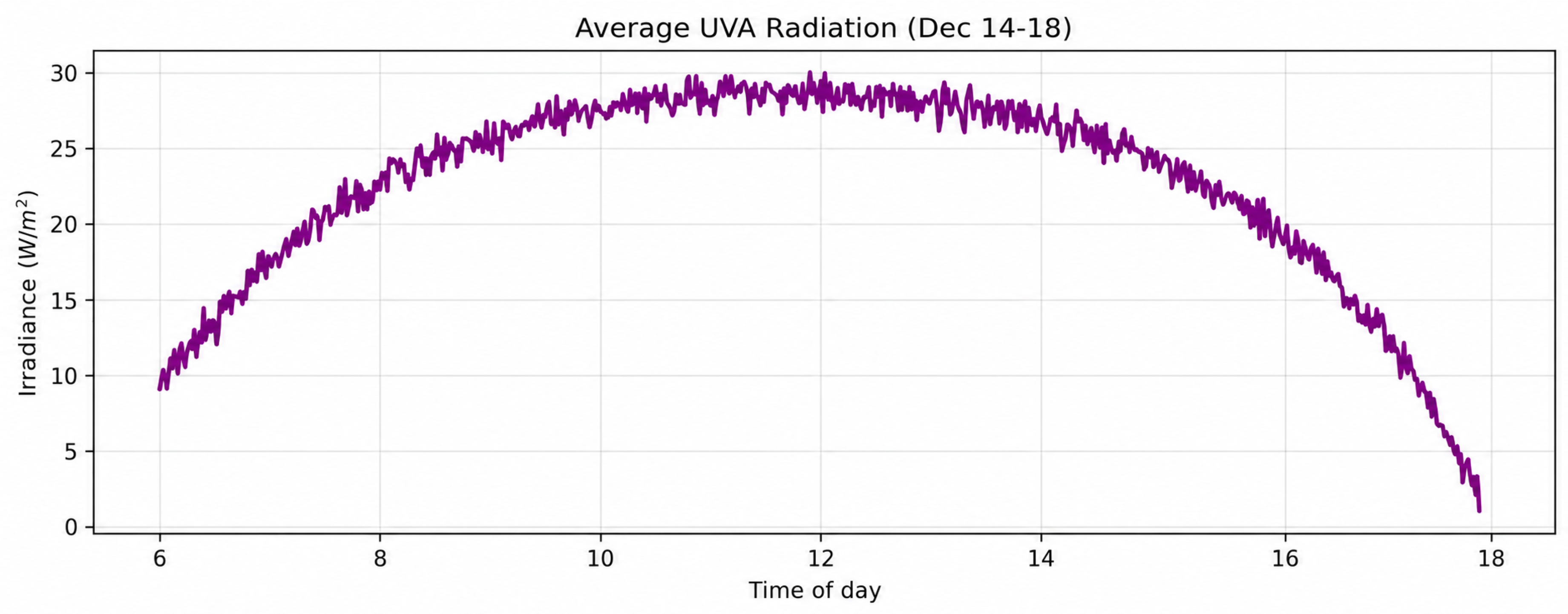
Figure 12.
UVB radiation during the time period
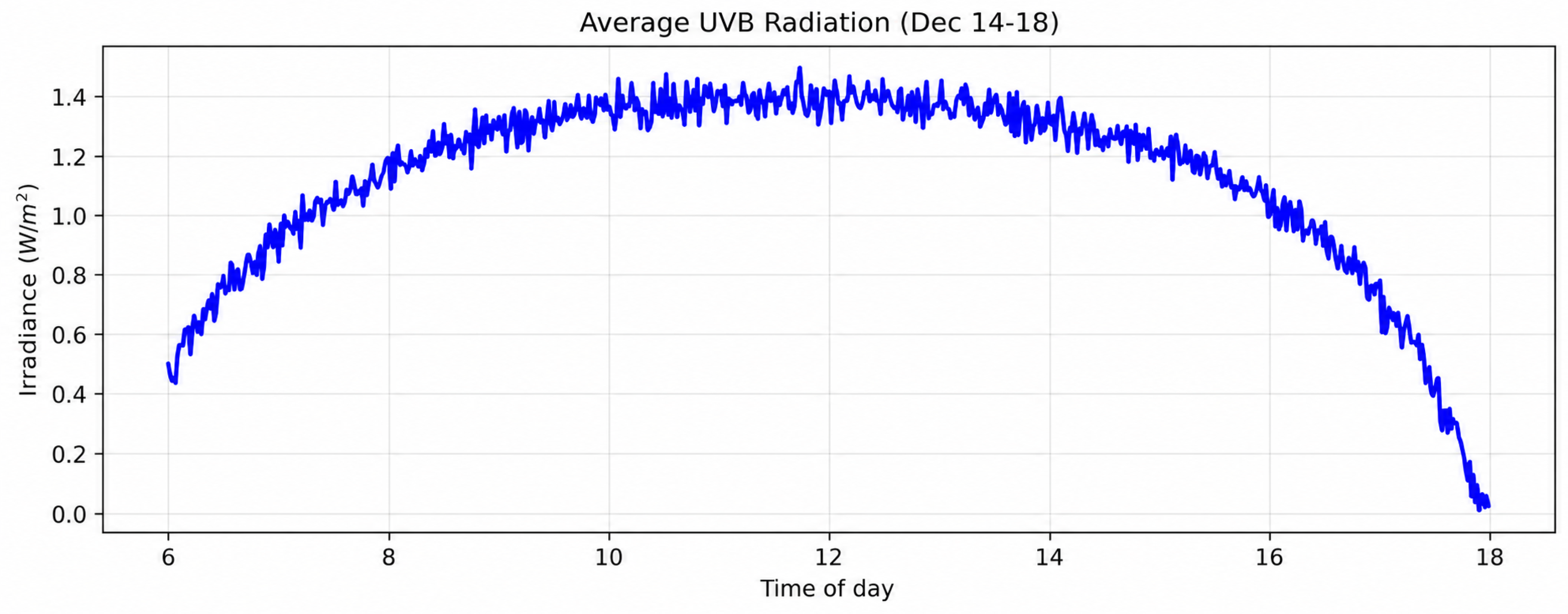
Figure 13.
UVC radiation during the day
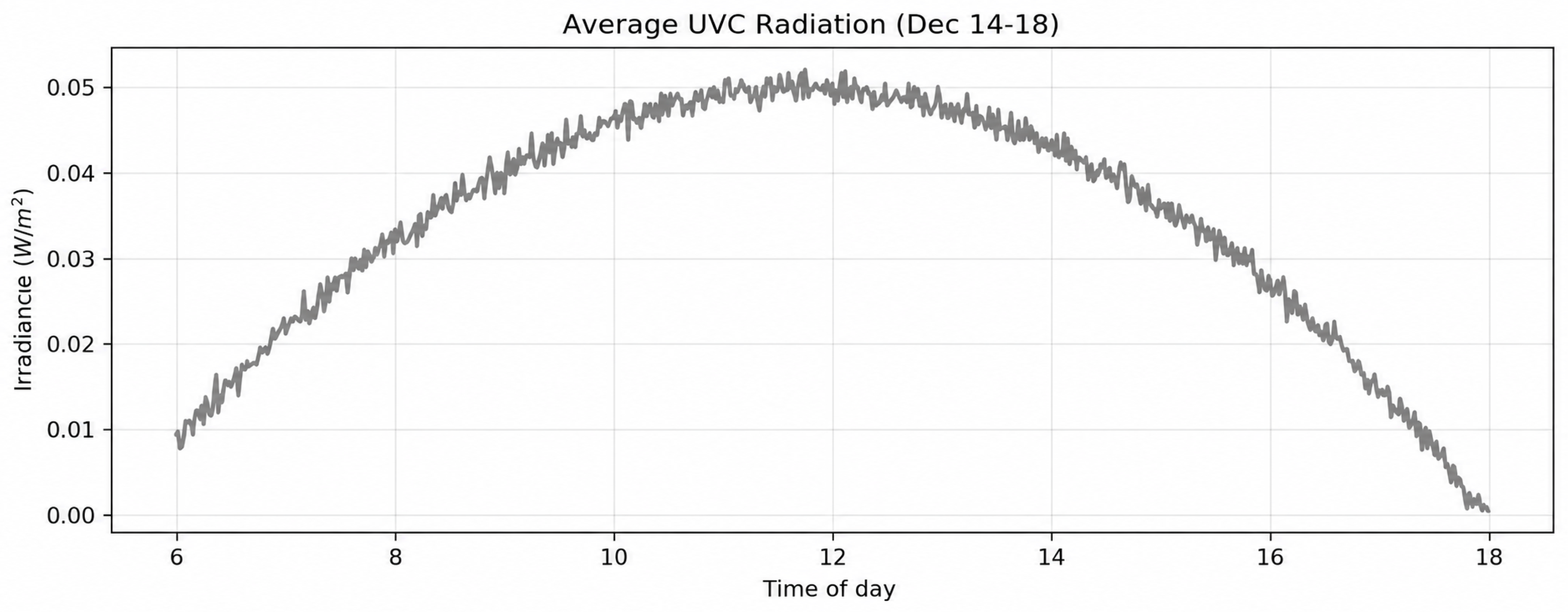
Figure 14.
Temperature over the course of the day
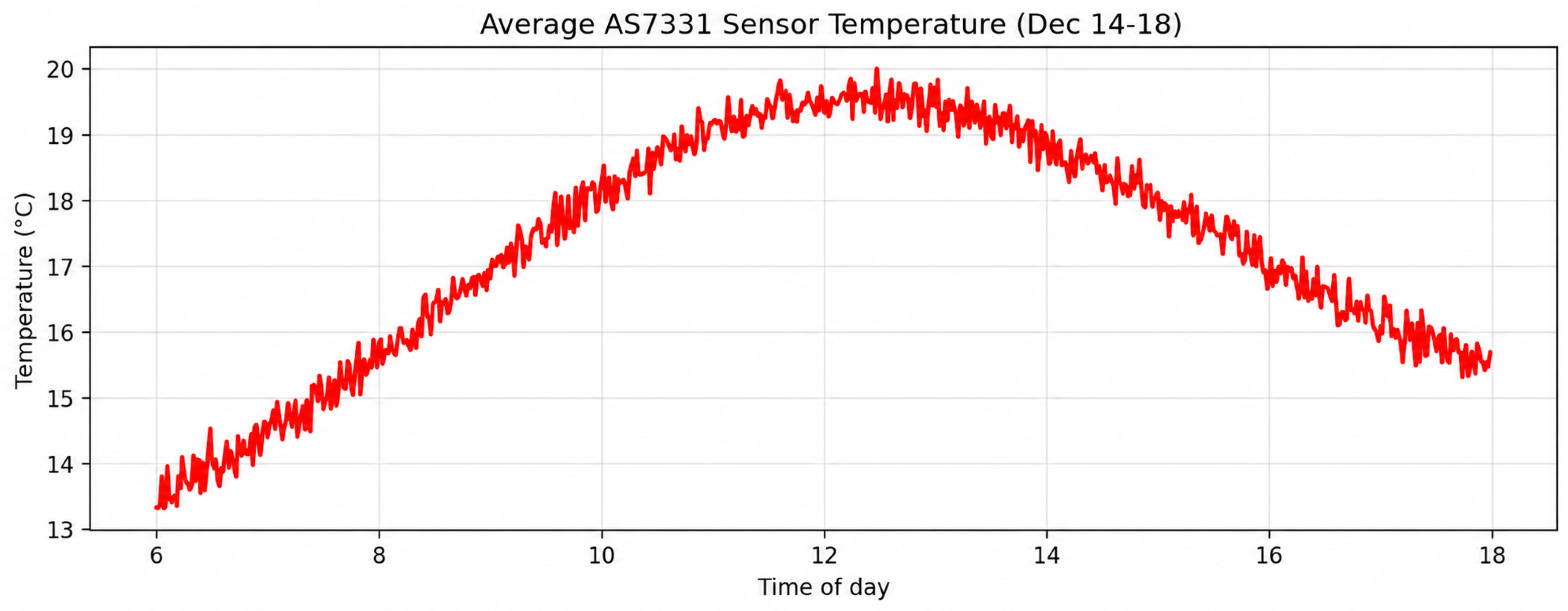
Figure 15.
Changes in azimuth and elevation angles over the course of the day
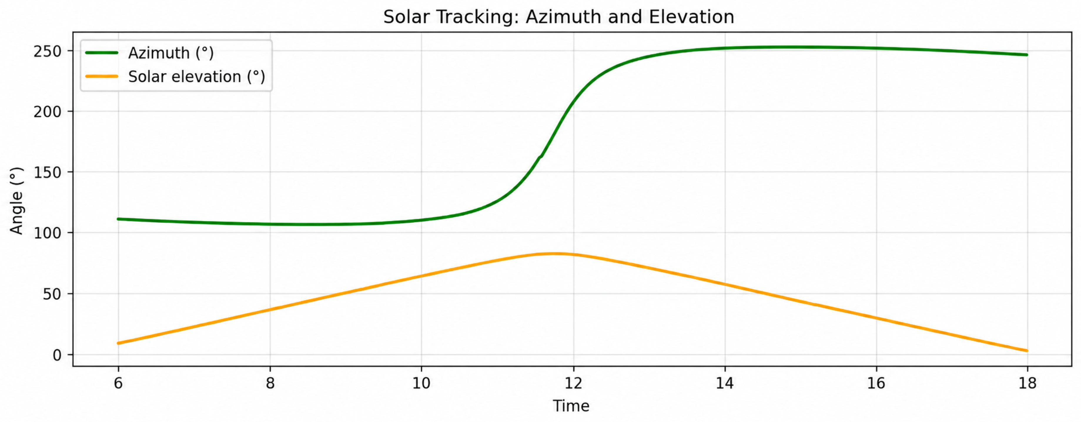
Figure 16.
Table of obtained data
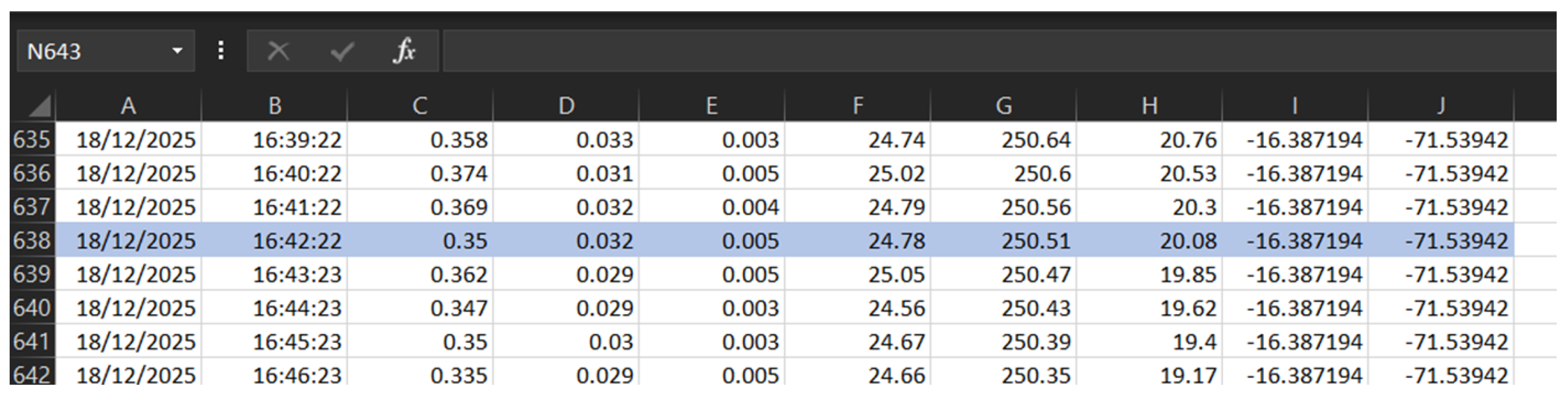
Figure 17.
Data from Stellarium
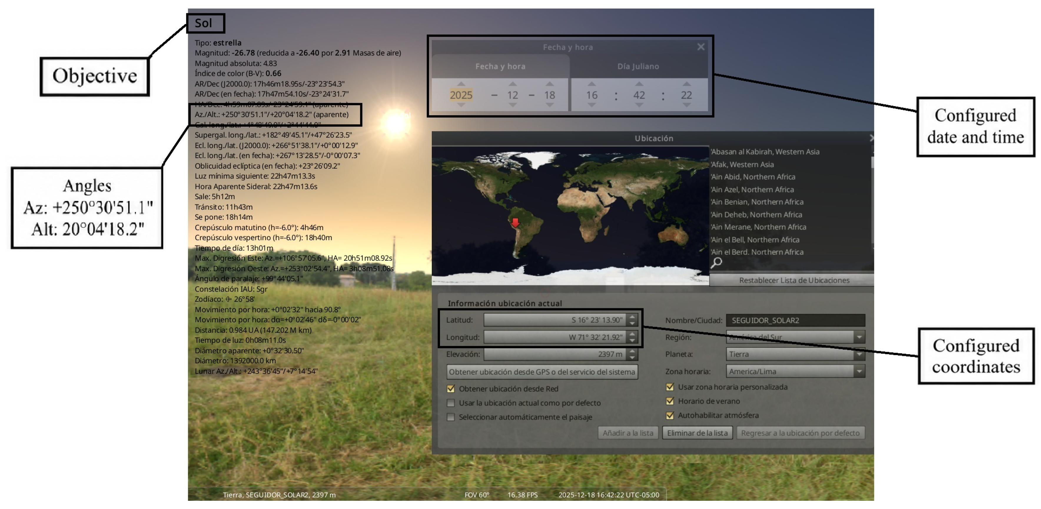
Table 1.
Comparison of error with different sources for a single point.
| System | Azimuth | Elevation | Azimuth Error | Elevation Error |
|---|---|---|---|---|
| Prototype | 0% | 0% | ||
| NREL SPA | ||||
| NOAA | ||||
| Stellarium |
Disclaimer/Publisher’s Note: The statements, opinions and data contained in all publications are solely those of the individual author(s) and contributor(s) and not of MDPI and/or the editor(s). MDPI and/or the editor(s) disclaim responsibility for any injury to people or property resulting from any ideas, methods, instructions or products referred to in the content. |
© 2026 by the authors. Licensee MDPI, Basel, Switzerland. This article is an open access article distributed under the terms and conditions of the Creative Commons Attribution (CC BY) license.
Copyright: This open access article is published under a Creative Commons CC BY 4.0 license, which permit the free download, distribution, and reuse, provided that the author and preprint are cited in any reuse.


