Submitted:
09 June 2026
Posted:
10 June 2026
You are already at the latest version
Abstract
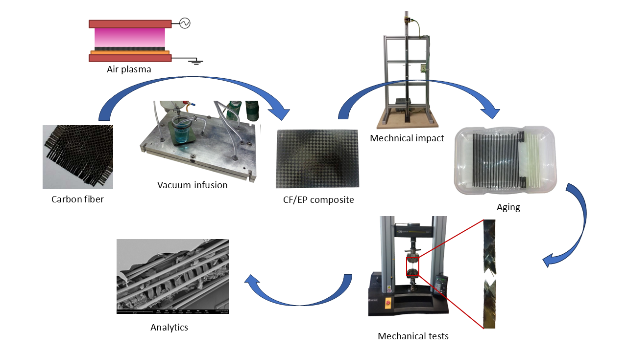
Carbon fiber reinforced epoxy resin composites were manufactured using the vacuum infusion technique. Composite samples were subjected to impact and then exposed to various weathering conditions. Static and dynamic mechanical tests were performed to evaluate the effect of an additional process step, a plasma treatment of the carbon fiber fabric before the composite is manufactured. Scanning electron microscopy and thermal analysis were used to get further information on the degree of damage after weathering. Treating the reinforcing carbon fibers with air plasma resulted in improved strength values and fatigue behavior of the epoxy resin composite. This performance enhancement persisted even after a low-energy mechanical stress and subsequent weathering.
Keywords:
carbon fiber reinforced epoxy
; air plasma
; impact
; aging
; mechanical properties
1. Introduction
Carbon fiber reinforced polymers (CFRP) are important materials due to their outstanding properties such as high strength-to-weight ratio, high stiffness, and corrosion resistance. However, the non-polar surface of the carbon fibers and incompatibility with the mostly polar polymer matrix result in low interfacial shear strength values due to the weak bonding between fiber and matrix. Modifying the fiber surface to improve fiber-matrix adhesion has therefore been a subject of research since the introduction of this composite material. Various methods have been investigated, including chemical and electrochemical etching, oxidation and coating of the fiber surface, microwave irradiation, plasma treatment, and the application of sizing agents and coupling agents [1,2,3,4]. As early as the 1980s, researchers investigated the effects of plasma treatment on carbon fibers [5]. This environmentally friendly method avoids the use of toxic chemicals and coatings. The main purpose of plasma surface treatment is to modify the chemical and physical structure of the fiber surface layer without affecting its bulk mechanical properties [6]. Numerous publications report on the etching, roughening, chemical conversion, and activation of the carbon fiber surfaces, studying the influence of the plasma treatment parameters to determine optimal process conditions [7,8,9,10]. Atmospheric pressure plasmas gained interest due to the use of simplified equipment compared to low-pressure plasmas. The treatment of carbon fibers with air or oxygen plasmas led to increased surface roughness, which improves mechanical interlocking [5,11,12], and to chemical modification through the formation of polar surface groups (-C=O, -COOH/-COOR, -COC, -C-OH) on the carbon fiber which promotes a stronger fiber-matrix bond [5,8,11,12,13]. Mechanical tests revealed improved mechanical properties of the resulting composite materials. Furthermore, they showed that the performance enhancement strongly depends on the plasma technique and the treatment parameters such as gas type, flow rate, treatment duration and power input [11,12,13,14,15].
Some studies have investigated the influence of plasma treatment of the reinforcing carbon fibers on the weather resistance of the composite material [16,17]. Air pressure plasma treatment of carbon fibers and mechanical testing of the composite material after UV/humidity weathering showed improved adhesion of the carbon fibers to the epoxy matrix. The tensile strength increased by 18% (un-weathered samples) and was 17% higher after exposure. Despite a significant increase in interlaminar shear strength (ILSS) of 24% through plasma treatment, physical damage (microcracking) occurred in the weathering experiment, with an ILSS loss of 7%, compared to 2% for the untreated samples [16].
A known risk of these materials is that composite materials can fail in service due to damage caused by low-energy impacts and moisture absorption. After an impact, the flexural properties of CFRP deteriorate, and the thermoset matrix tends to absorb moisture. Some studies address the aging of carbon fiber epoxy resin composites [18,19] after a low-energy impact. They reported an increase in water absorption with increasing impact energy [18,19] and that the absorbed water significantly alters the strength, stiffness and fracture mode of the composites. Exposure to hot/humid environments typically leads to plasticization, hydrolysis, interface delamination, and microcracking. Charpy impact test and three-point bending test were performed to determine the influence of thermal aging on the mechanical properties [20]. Specimens aged at temperatures below the glass transition temperature showed a post-curing effect with an enhanced crosslink density. Impact and bonding strength increased, while flexural stiffness decreased.
Investigations of carbon fiber-epoxy resin composites after low-velocity impact (experiment and finite element simulation) [21] and post-impact compression tests employing industrial CT scanning were carried out to get information on the failure mechanism and the effect of impact energy on residual compressive strength [22]. After impact, pits on the front side and matrix cracks on the back side were observed.
In practical application, various factors act simultaneously on the composite material, such as mechanical loads, temperature changes, humidity, and chemical substances. Impact damage is widely recognized as one of the most damaging types to composite materials, as it dissipates the incident energy through a combination of matrix damage, fiber fracture, and fiber-matrix debonding. This study simulates various weathering scenarios and determines the mechanical properties of composite materials after mechanical damage and subsequent aging using tensile, compression, three-point bending and fatigue test. The focus of the investigations is the comparison of two CF composite materials, one of which is distinguished by an additional plasma treatment of the carbon fibers before the manufacturing of the composite material. The water absorption of the laminates and the glass transition temperature of the artificially aged matrix material are determined and discussed.
The tests were carried out to determine the residual strength of the samples after impact and moisture absorption. In each series of tests, the experimental parameters for the reference laminate and plasma-treated laminate were identical, so the performance differences can be attributed to this additional process step. To our knowledge, no such comparative studies have been described before. Due to the large number of influencing factors, an evaluation of the results in comparison to previously published data is only possible to a limited extent.
2. Materials and Methods
2.1. Composite Preparation
The CF reinforced epoxy composites were prepared using the vacuum infusion method. Five layers of the carbon fiber fabric HexForce PrimeTex 48192 C (Hexcel corporation) were placed in a special mold tool with a distance holder of 1.2 mm. The CF fabric cuts were stacked in a ±45° orientation. A mixture of 200 g EPIKOTE-Resin MGS RIMR 135 and 60 g EPICURE-Curing Agent MGS RIMH 1366 (Momentive Specialty Chemicals Inc.) was heated to 70 °C and degassed for 5 min and then injected into the evacuated mold tool. After complete soaking of the CF staple the composite material remained for 48 hours in the tool. Then it was tempered for 15 hours at 80 °C in a drying cabinet. From the final sample sheet of the size 300 x 210 mm2, different large rods were milled out using a CNC table milling machine. All test bars were ground and polished on the sides.
Immediately prior to vacuum infusion, some of the carbon fiber mats were treated with an air plasma using a plasma system based on the principle of dielectric barrier discharge (DBD). A scheme and a photograph of the plasma treatment system are shown in Figure 1. The upper electrode consists of a rectangular Al₂O₃ tube filled with bronze powder and is connected to a power supply that generates a pulsed voltage (≈ 19 kV peak) with alternating polarity and a pulse duration of approximately 2 µs. The lower electrode (aluminum) is grounded and covered with a 3 mm thick dielectric made of float glass. The CF fabric mats are placed onto the dielectric and secured using a PVC frame. The plasma head (the high-voltage electrode, integrated into a plastic housing, with process gas supply) is mounted on a cross-table and can be moved along three axes.
The plasma head was moved at a constant speed of 2 m/min, 5 mm above the carbon fiber mats. The fiber material was treated for a total of 6 s on each side. The JK50kV-P power supply (500 W input power, 60% utilized output power) was pulsed at 50 kHz. A laminar airflow of 30 L/min was used as the process gas. More detailed information on this plasma system can be found in ten Bosch et al. [23] and Wascher et al. [24].
Five sheets of each CF reinforced epoxy composite material and two sheets of epoxy resin were produced using the same mold tool.
2.2. Composite Characteristics
The composite material was characterized by fiber volume fraction and moisture uptake during the aging experiment, while the matrix material was characterized for its glass transition temperature before and after the aging experiment.
The fiber volume ratio was determined according to EN 2564 by digesting the laminate with concentrated sulfuric acid and hydrogen peroxide. To determine moisture uptake, eight unaged samples (each about 2 g) were weighed with an accuracy of 0.1 mg. Weight gain was measured at seven time-intervals during the aging process.
Differential scanning calorimetry (DSC) measurements of the matrix material were carried out at a DSC 3+ (MettlerToledo) using software STARe. The tests were conducted in nitrogen gas with a flow rate of 30 mL/min. Samples of 15 ± 0.5 mg were heated two times from 25 °C to 125 °C. The heating and cooling rates were 20 K/min. The glass transition temperature Tg was determined according to ISO 11357-2 by analyzing the heat flow curves measured during the second heating cycle.
Light microscopy images were taken with a stereo microscope Stemi 508 (Zeiss, Germany) using a USB camera and Axiovision software. The electron micrographs were measured with a JEOL JSM-5600LV (Japan) or a Phenom Pro G6 Desktop SEM (Thermo Fisher Scientific, USA) in high vacuum mode with an accelerating voltage of 15 kV. The samples were sputtered with a thin gold coating to omit charging effects of the specimen.
Attenuated total reflectance Fourier transform infrared (ATR-FTIR) spectra were recorded by using a PerkinElmer Frontier spectrometer equipped with an ATR module (Golden Gate Single Reflection Diamond ATR, Specac, USA) to identify the chemical composition of the composite surfaces before and after weathering. Additionally, FTIR analysis was performed using the potassium bromide (KBr) pellet technique. All spectra were recorded between 4000 and 400 cm-1 at a resolution of 4 cm-1, and a total of 64 (ATR) or 16 scans (KBr pellets) were made. Spectra processing was performed using the Spectrum software. All spectra were baseline corrected and normalized.
2.3. Artificial Weathering and Mechanical Impact
For each of the different aging experiments, six samples were investigated. The artificial weathering with UV radiation was carried out in accordance with ISO 4892-3 using a UV lamp UV-8 S/L of Herolab (Germany). The lamp works at 254 nm and 365 nm wavelength and has according to the manufacturer at 150 mm distance a radiation intensity of 680 µW/cm3 and 950 µW/cm3, respectively. The samples were placed 100 mm apart from the UV lamp and exposed 8 h daily to the UV radiation. In total the samples were exposed 120 h to UV.
The artificial weathering in water and aqueous solutions, respectively, was carried out with mechanically pre-damaged samples and lasted in total 30 days for each sample. A sample set was stored in water at 70 °C for 8 hours and then, after blotting the moisture from the surface, exposed to -18 °C for 16 hours. Two sets of samples were stored in aqueous solutions of KOH (20 wt.%) and of MgCl2 (20 wt.%), respectively, at ambient temperature. A fourth set was stored in MgCl2 solution (20 wt.%) for 16 hours at 20 °C and then for 8 hours at 70 °C.
The mechanical damages to the test bars were produced in the same way as in the drop weight test. The impact energy was 4.05 J. For this purpose, a 625 g dart was placed 0.66 m above the samples, leading to an impact speed of 3.6 m/s. This value is in the low velocity range (1-10 m/s) [25] which means that the load can spread in the whole structure.
2.4. Mechanical Tests
The static mechanical tests were carried on a universal testing machine Instron 5567 (Illinois Tool Works inc. USA) in accordance with ISO 527, ISO 14126, and ISO 14130 but slightly deviating sample geometry. The software Bluehill was used for controlling the experiments and evaluation of the measuring data. For tensile testing, specimens 120 mm long, 10 mm wide and 1.2 mm thick were used. The span length was 80 mm. The measurement was conducted with a constant crosshead speed of 2 mm/min and stopped at a load drop of 40%.
Test bars of the same dimensions were used for the compression tests. The span length was 8 mm to avoid a risk of buckling. The crosshead speed amounted to 1 mm/min. The tests were manually stopped after reaching the maximum load.
The fatigue tests were carried out on a testing machine Instron E3000 (Illinois Tool Works inc. USA) using the software Instron Console and Instron WaveMatrix for controlling the experiments. In preliminary studies the power level was determined at which the samples show 5 x 10⁴ – 10 x 104 tension cycles. The fatigue tests were conducted at stress ratio 0.1 with frequency 5 Hz at a medium load level of 708 N with a load amplitude of 580 N sinus form. The experimental conditions allowed a pure tensile cyclic loading; thus, the stress of the composite samples was tensile during the entire cycle. Test bar dimensions and span length were the same as in the tensile testing.
Each value given represents the average of six individual samples.
3. Results and Discussion
3.1. Properties of the Composites as Prepared
The fiber volume fraction of the two laminate types was very similar at 47.0% (±1.5%) for samples without plasma pre-treatment and 47.9% (±1.1%) for samples with plasma pre-treatment, respectively. The measurement results were within the typical range, and they were mainly affected by the number of carbon fiber layers and the dimension of the manufacturing tool. Plasma treatment of the reinforcing fibers led to better reproducibility of the fiber volume fraction of the laminates.
The results of the static mechanical tests of the two laminate types were very similar (see Table 1). However, the strength values of the plasma-treated CFRP samples showed mostly smaller standard deviation, thus a larger homogeneity. In tensile test, compression test, and three-point bending test, slightly enhanced strength values (see Table 1) of the pt-CFRP were measured. The differences in the measured values were in the range of a few percentage points and within the error limits. In tensile and compressive tests, the ±45° laminates were simultaneously subjected to shear stress. The uniaxial loading generated biaxial stress. Thus, all of these mechanical tests provided information about shear stress behavior and fiber matrix adhesion. The improvement in strength values was small because the experiments were not conducted with an optimized plasma treatment time. It is known from literature and previous studies that plasma treatment times of only a few seconds are sufficient to modify both the surface of carbon fibers [26] and the sizing applied to them [27]. Therefore, we focused on short plasma treatment times of the carbon fibers, which can be easily integrated into the manufacturing process. Other authors who observed maximum ILSS values and other strength values in case of a 15-minute plasma treatment [28] also pointed out the danger of long exposure times and high powers, as these can partially destroy the surface of the carbon fibers due to further oxidation of the previously generated surface groups.
Although the short plasma treatment of the reinforcing material did not lead to a significant improvement in strength values, larger differences were observed in the fatigue test. Under repeated tensile stress, the plasma-treated samples showed increased stability. The number of load cycles until failure was improved by more than 30%.
The surface groups generated by air plasma increase the polarity of the carbon fibers and improve the adhesion between the fiber and the epoxy matrix. This leads to a slightly faster vacuum resin infusion and better bonding between the fiber and the matrix. In addition to dipole-dipole interactions, the formation of chemical bonds between the surface groups of the carbon fiber and the resin components (both the epoxy resin and the amine hardener) is likely. Both the hydroxyl and carboxyl groups can react with the epoxide ring of bisphenol A diglycidyl ether, forming a new hydroxyl group in each case—alongside an ether (1) or ester (2), respectively. Furthermore, the carboxylic group can react with the amino group of the hardener to form a carboxylic acid amide (3). The bonding sites formed in this way between the fiber and the matrix can contribute to improved fiber-matrix adhesion. The surface groups may therefore be involved in the curing process of the resin matrix.


Reactions involving surface groups compete with the reaction between the resin and the hardener. Since the number of surface groups is comparatively low, identifying their reaction products proves difficult. Further investigations are planned to evaluate the fiber-matrix bonds.
3.2. Effects of Artificial Weathering
Both types of CFRP were aged during the 30 days of artificial weathering. As shown in Figure 2, under all conditions, the slightly enhanced strength values of the plasma-treated composite material were also detectable after the different aging procedures. Also in the dynamic investigations, these samples showed the better stability and the higher number of load cycles (see Figure 5). However, under nearly all weathering conditions a loss in performance was measured.
3.2.1. UV Exposure
The 120-hour UV treatment of the CFRP had no significant effect on the strength data determined in tensile, compression and three-point bending tests. Only the ILSS values showed a slight decrease and were 8% lower than in the reference samples. Under the influence of UV light, the epoxy resin undergoes various changes: a post-curing and cross-linking reaction as well as a photo-oxygen aging reaction [29]. These two reactions have opposing effects on the strength of the composite material and compensate for each other to a certain extent. This is evident from the changes in mechanical properties measured after different irradiation durations. For short irradiation durations of 4 and 12 hours, a slight increase in ILSS of 5.3% and 1.2%, respectively, was reported [30]. Long-term treatment exceeding 720 hours led to a decrease in the flexural strength of the CFRP by 6% [29] and a decrease in ILSS by 20% [31]. Due to the limited penetration depth of the radiation, UV aging affected the surface layer of the epoxy resin. Photooxidation and chain fragmentation led to degradation of the outermost resin; post-curing and cross-linking reactions delayed the loss of quality. With a UV irradiation of 120 hours, the results presented here are in a range where density, and hardness of the epoxy are slightly increased and flexural and impact strength of the composite material are slightly reduced [29].
According to FTIR studies, the photooxidation of epoxy/amine samples leads to the almost complete oxidation of the DGEBA units (diglycidyl ether of bisphenol A) down to a depth of 2-3 µm [32]. Chemical changes occur both in the DGEBA structural unit and at the bonds formed with the crosslinker [33]. The comparison of the IR spectra of UV-irradiated CFRP samples with the spectra of control samples (see Figure 3) confirmed this. After UV irradiation, the very weak bands at 3054 cm-1 and 932 cm-1 (C-H stretching and bending vibration of the epoxy group of DGEBA) disappeared. The occurrence of very intense absorption bands in the region of C=O stretching vibrations and O-H and N-H bending vibrations (1730 cm-1 ketone, 1648 cm-1 amide and hydrogen-bonded water) was striking. Furthermore, band broadening, intensity gain and shift of the O-H stretching vibration band from 3385 cm-1 to 3294 cm-1 were observed, which is a typical result of hydrogen bonds. The intensity gain of the symmetrical CH3 bending vibration band at 1383 cm-1 supports the conclusion of the formation of acetyl groups.
Since UV radiation does not penetrate deeply into the samples, it has only a minor influence on their physical properties. This was confirmed in the fatigue test, which showed only a slight decrease of 5% in the number of load cycles (see Figure 5).
3.2.2. Weathering Experiments After Low-Velocity Impact
The composite material manufactured was not completely free of defects. Microcracks and air inclusions could not be completely avoided. Using a drop weight, the composite samples were mechanically damaged to create comparable initial conditions for the artificial weathering experiments. Since the depth of the dent and the damage area depend on the energy of the low-velocity impact [34] and the thickness of the composite material affects the laminate fracture mode [25], preliminary tests with different drop weights were carried out. For the studies on aging behavior, a low-velocity impact of 4 J energy was applied, which led to a barely visible impact damage. Only a flat, almost round indentation on the front was visible to the naked eye. Its diameter was between 3 and 5 mm. Microscopy images confirmed (see Figure 4) the matrix deformation on the front and showed a matrix cracking within this area. The back face remained unaffected. Besides these two damage patterns observed in the light microscopy image, interfacial debonding, interlaminar delamination, lamina splitting, fiber breakage, and fiber pull-out are typical damage mechanisms after low-velocity impact [22,35,36].
Figure 4.
Microscopy (a) and SEM images (b-d) of a CFRP specimen after low-velocity impact.

Figure 5.
Dynamic tension test (Note the deviating experimental conditions for EP samples).

SEM images of the center and periphery of the indentation provided more detailed information (see Figure 4). In the center of the impact position the resin matrix was compressed and crushed, and fiber breakage was observed. At the periphery, cracks in the resin matrix, fiber breakage and fiber pull-out became visible. Images of the back side showed that the barely visible damages did not penetrate the composite.
Artificial weathering of mechanically pre-damaged samples in various aqueous solutions led to differing losses in strength. Samples stored in MgCl2 solution either at ambient temperature or with daily temperature fluctuations between 20 °C and 70 °C were rather robust with respect to the solution. In the static mechanical tests, their strength values decreased only by a few percent. ILSS values were about 6-8% lower after storage in MgCl2 solution. Repeated stress in the dynamic mechanical test resulted in a reduced fatigue life of about 30%. As carbon fiber and epoxy resin are chemically stable in the slightly acidic and not very aggressive solution there must be another reason for loss of performance. The main effect of storing the composite material in a MgCl2 solution was the diffusion of water into the resin, leading to swelling-induced stresses in the matrix. The extent of the damage depends on the concentration of pores and microcracks as well as on the quality of the fiber-matrix interface [37] and increases with rising temperature. The influence of temperature is also reflected in differences in water absorption (see Figure 6) and is discussed below. The samples immersed in MgCl2 solution at 20 °C and 70 °C showed slightly lower strength values than those stored in the same solution at ambient temperature. However, the effect was minimal. Thermal aging of the resin matrix is only observed when the treatment temperature is above the glass transition temperature [33]. The different coefficients of thermal expansion of fiber and epoxy resin are the main reason for the thermal stress in the anisotropic composite material.
Samples treated with KOH solution showed a remarkable loss of quality. Tensile strength dropped by about 10% and compression strength by almost 20%. Looking at the results of the three-point bending test, the strongly alkaline solution caused the greatest loss of quality at all. The ILSS of the CFRP samples decreased by 21% while those of the pt-CFRP samples decreased by 18%. The serious damage of the composite material was also evident in the fatigue test, in which the maximum number of load cycles was reduced by 41% for the CFRP samples and 53% for the pt-CFRP samples. Solution uptake, swelling of the resin and chemical attack of the strong base on the resin matrix, combined with the cleavage of the weak fiber matrix bonding, caused the damage of the composite material. Although no new absorption bands were visible in the FTIR spectra (see S1), it must be assumed that the alkaline solution promoted the hydrolysis reaction of the epoxy resin [38]. Mechanical tests on pure resin samples showed analogous behavior after treatment with KOH solution.
A remarkable loss in strength was also observed for all samples stored in water and exposed to temperature fluctuations between minus and plus degrees centigrade. Tensile strength dropped by about 12% and compression strength by almost 20%; thus, the water-aged samples showed in these two tests the greatest loss in performance. The three-point bending test revealed a slightly better picture compared to the KOH treatment. The ILSS of the CFRP samples decreased by 15% while those of the pt-CFRP samples decreased by 17%. The deterioration of the ILSS values was in the same range as the values published for the aging of CF/EP under hot/humid conditions [30]. Large temperature fluctuations of almost 90 degrees and daily composite sample storage for several hours at sub-zero temperatures enhanced mechanical damage of the brittle resin matrix. Furthermore, the resin contraction and the expansion of the carbon fibers during the cooling of the composite samples led to stresses at the fiber-matrix interface. The difference in the coefficient of thermal expansion of intrinsic fiber and disordered surface layer as discussed for low and cryogenic temperatures [39] probably plays a minor role in this context. Temperature fluctuations can lead to cracking in the outer layer. Freezing of water in pores and microcracks due to inner tension stress caused additional stress. Investigations at more drastic temperature fluctuations as reported by Wang [40] showed an ILSS reduced to about 74%. The authors discussed cyclic freezing and thawing as one reason for this. SEM images of the delamination fracture surface showed that carbon fiber and epoxy resin were almost completely separated, and the resin was severely damaged [40]. Comparing the strength of the two composite materials, the pt-CFRP showed the higher absolute values in all static mechanical tests. The strong damaging effect of these weathering conditions was also reflected in the fatigue test. For samples CFRP and pt-CFRP, the number of load cycles was reduced by 62% and 50%, respectively, when exposed to water under temperature fluctuations from minus 18 °C to plus 70 °C. These samples exhibited the strongest water absorption with more than 1.2 wt.-%. The change between liquid (water) and solid (ice) caused additional mechanical stresses in the composite material.
For samples weathered under the same conditions, the loss in mechanical performance was similar in all three static tests. Microcracks, pores, and impact damages like fiber-matrix debonding, fiber breakage and fiber pull-out affected the results of the mechanical tests. The considerable contribution of the matrix material to the loss in mechanical performance became visible when investigating pure epoxy resin samples. The strength values of the epoxy resin specimens showed a similar tendency for all mechanical test results (see S2). Several studies have shown that composite material response and epoxy resin response to physical aging are similar. The authors concluded that physical aging has only a minor influence on the strength of the fiber-matrix interface [41]. However, larger differences between the quantitative changes in the composite materials and the resin matrix, especially during KOH treatment and hot/wet treatment, indicate that a chemical attack on the weak fiber-matrix bond must also be taken into account. In this connection the fiber surface plays an important role [37]. Thus, besides fiber-matrix bond and load transfer from matrix to fiber, the properties of the matrix are important for the performance of the composite material. Swelling of the resin, thermal expansion and contradiction, hydrolytic degradation and photo-oxidation were the main causes of deterioration in matrix quality.
Investigations into fatigue behavior revealed clearer differences between the two composite materials (see Figure 5). Whether in the reference samples, the UV-treated samples or the artificially aged samples – the plasma-treated samples always showed a higher number of load cycles. The increase was 33% for the reference sample and 27% for the UV-treated sample. The differences were similar or even greater when the samples were mechanically damaged and subsequently stored in solutions. The number of load cycles of the pt-CFRP was 25% (MgCl2+ΔT), 29% (MgCl2), 71% (KOH) and 72% (H2O+ΔT) higher than that of the untreated composite material.
The cyclic loading stress test showed that the UV treatment has only a minor influence on the fatigue behavior of the composite material. All other samples, which were stored in various solutions after a low-energy impact, showed a noticeable loss of quality. Storage in MgCl₂ solution at room temperature or at 20 °C/70 °C reduced the number of cycles to about one-third. Storage in KOH solution or in water at -18 °C/70 °C had a significantly stronger effect; the number of load cycles was reduced to about half.
Investigations of the pure epoxy resin showed a similar response to UV exposure and storage in aqueous solutions. Reference and UV-treated samples failed after a similar number of load cycles. The treatment with MgCl2 solution reduced this number by about 11%. The effect of the strong alkaline KOH solution was significant. The number of load cycles was reduced by 31%. Even stronger was the effect of water in combination with drastic temperature changes. Under these conditions, the number of load cycles was reduced by 39%. The quality loss in the resin samples was also less than in the composite samples. This means that, in addition to damage to the matrix material (chemical and mechanical damage such as polymer degradation, microcracks, pores, water absorption), damage to the fiber-matrix interphase (load transfer in the damaged resin area) also contributes to the performance loss.
3.3. Water Uptake and Glass Transition
Failure of the composite material due to impact damage and moisture absorption poses a risk to its application. Therefore, further information should be obtained by measuring the water absorption of both composite materials during the weathering test (see Figure 6).
The composite material exhibits pores and microcracks. Mechanical stress increases the number and size of microcracks. Because epoxy resin has polar groups, an interaction occurs between the resin and water, leading to water absorption. Water uptake increased noticeably in the first few days and only slowly after 10 days (see Figure 5). After about 20 days, the samples stored in MgCl2 solution approached the saturation point, and the absorption capacity remained almost constant.
CF composites immersed in MgCl2 solutions but exposed to temperature fluctuations absorbed more water. The temperature dependence of water absorption is consistent with the results that Ellyin et al. [42] observed for glass fiber reinforced epoxy resin when stored in distilled water. Samples immersed in water showed an increase in weight over a period of 30 days. These samples showed the strongest water absorption by far. The values of 1.2% for pt-CFRP and 1.4% for CFRP were in good agreement with literature data [19,40,43]. A different behavior was observed in the samples stored in KOH. After low water absorption during the first days, the water content remained almost unchanged for a period of 15 days before increasing noticeably after 26 days. This behavior is most likely due to a chemical attack of the strong base on the resin matrix. Breaking chemical bonds in the epoxy resin makes the polymer network of the thermoset more flexible and allows the solution to diffuse. Besides the composition and temperature of the solution, the extent of the mechanical damage also influences the water absorption. Under all conditions, the plasma-treated samples consistently showed lower water absorption than the untreated ones.
The influence of the weathering conditions on the resin matrix was investigated using differential scanning calorimetry (DSC). All samples were heated twice to avoid overheating caused by releasing mechanical tensions within the resin samples. The glass transition temperature Tg was determined using the half-step height method according to ISO 11357-2. The evaluation of the DSC experiments revealed a somewhat different picture (see Figure 7). The Tg values of the reference sample and the UV- treated resin sample were practically identical at 90 °C and 89.8 °C, respectively. This result is in good agreement with studies by Grassie et al. [44], who found that crosslinked epoxy resin is relatively light-stable and long irradiation times are required for photochemical degradation. After 183 hours of UV irradiation, the authors were able to detect traces of some volatile products (CO2, H2O, NH3).
Resin samples stored in MgCl₂ and KOH solution at room temperature showed a significant decrease in the glass transition temperature. Possible causes include the diffusion of water into the network structure and swelling. Degradation of the polymer structure could not be detected by IR spectroscopy.
Storing the resin in MgCl2 solution at elevated temperatures led to an increase of the Tg value. A similar observation was made during the heat treatment of epoxy resin samples in the absence of water [45]. Heat treatment of the epoxy resin at temperatures near the glass transition temperature leads to post-curing and an improvement in quality. Thermal degradation of cured epoxy polymers is only observed at temperatures above 300 °C [46].
The greatest decrease in the glass transition temperature was observed in the resin sample that was immersed in water and subjected to a daily temperature change from 70 °C to -18 °C. Furthermore, this resin sample exhibited the highest water absorption. The different temperature dependence of the coefficient of expansion of resin and absorbed water can cause stresses in the polymer network and lead to microcracks.
The DSC analyses revealed the different effects of the solutions on the matrix material. Changes in the matrix material during the weathering must be considered when evaluating the composite material properties.
3.4. SEM
Slightly enhanced mechanical strength, improved fatigue behavior, and lower water uptake of the pt-CFRP samples observed under all test conditions are related to the inner structure of the laminate.
SEM images (see Figure 8) of two reference samples recorded after tensile test make some differences visible. Looking at the fracture zone, the CFRP sample shows a sharp fracture edge and relatively loosely lying fiber bundles. The fracture edge of the pt-CFRP sample is jagged and the fiber bundles embedded in the resin matrix. Plasma treatment activated the fiber surface, led to a better impregnation of the fiber bundles during the resin infusion and improved fiber-matrix bonding. This has a positive effect on impact resistance. The area of impact-induced microcracks is reduced. By reducing micro-damage and improving bonding, material performance can be increased. Furthermore, plasma treatment allows the production of composites with fewer microcracks and probably of lower porosity. Fewer microcracks are available to join each other while dynamically stressed. Failure modes after impact of tensile force were matrix break, fiber break, fiber pull-out, and delamination.
4. Conclusions
A short plasma treatment of carbon fiber fabrics with an atmospheric air plasma resulted in a slight improvement in the mechanical properties of the CF reinforced epoxy resin composite. Tensile strength, compressive strength and interlaminar share strength increased by up to 5%. The dynamic test provided a clearer picture. The fatigue behavior of the composite material was improved; the number of load cycles increased by 30%.
UV irradiation of the composite samples resulted in a minimal loss of static mechanical strength and fatigue behavior. In all mechanical tests the plasma-treated samples showed the higher experimental data. UV light-induced reactions, photochemical degradation and crosslinking reaction of the epoxy resin all proceeded close to the surface of the composite material and compensated each other.
Aging of mechanically damaged composite samples in various aqueous solutions led to a significant reduction in mechanical properties. The greatest decrease was observed when the samples were stored in KOH solution or when hydrothermally aged. ILSS decreased to about 80% compared to the reference samples and the fatigue resistance to 40 - 50%. In all mechanical tests, the plasma-treated composite samples showed better performance than the untreated.
The aging behavior of the composite material and the thermoset matrix was similar. Stresses in the matrix caused by water absorption and matrix swelling caused a decrease of mechanical strength and load cycles.
Furthermore, the fiber-matrix interface with its weak fiber-resin bonds also determines the mechanical strength of the composite material and its decrease due to weathering. The most significant decrease is observed during aging in KOH solution and during hydrothermal aging.
Supplementary Materials
The following supporting information can be downloaded at the website of this paper posted on Preprints.org, Figure S1: FTIR spectra of epoxy resin before and after UV-exposure and after storage in KOH; Figure S2: Strength values of CFRP, pt-CFRP and epoxy resin after mechanical impact and aging.
Author Contributions
Conceptualization, H.W. and G.O.; methodology, H.W., S.H. and G.O.; validation, H.W. and G.O.; investigation, H.W.; resources, G.O. and S.H.; writing—original draft preparation, GO. All authors have read and agreed to the published version of the manuscript.
Funding
This research received no external funding.
Acknowledgments
The authors thank Martin Bellmann and Richard Wascher for their assistance with the plasma treatments and Dr. Roger Skarsten for proofreading the manuscript.
Conflicts of Interest
The authors declare no conflicts of interest.
References
- Ansari, M.S.; Zafar, S.; Pathak, H. A comprehensive review of surface modification techniques for carbon fibers for enhanced performance of resulting composites. Results Surf. Interfaces 2023, 12, 100141. [CrossRef]
- Joo, J.-H.; Kim, S.-H.; Yim, Y.-J.; Bae, J.-S.; Seo, M.-K. Interfacial Interlocking of Carbon Fiber-Reinforced Polymer Composites: A Short Review. Polymers 2025, 17, 267. [CrossRef]
- Tiwari, S; Bijwe, J. Surface Treatment of Carbon Fibers – A Review. Procedia Technol. 2014, 14, 505-512. [CrossRef]
- Sharma, M.; Gao, S.; Mäder, E.; Sharma, H.; Wei, J.Y.; Bijwe, J. Carbon fiber surfaces and composite interphases. Compos. Sci. Technol. 2014, 102, 35-50. [CrossRef]
- Mujin, S.; Baorong, H.; Yisheng, W.; Ying, T.; Weiqiu, H.; Youxian, D. The Surface of Carbon Fibres Continously Treated by Cold Plasma, Compos. Sci. Technol. 1989, 34(4), 353-364. [CrossRef]
- Li, R.; Ye, L.; Mai, Y.-W. Application of plasma technologies in fibre-reinforced polymer composites: a review of recent developments. Compos. Part A 1997, 28A, 73-86. [CrossRef]
- Kusano, Y.; Andersen, T.L.; Sørensen, B.F.; Michelsen, P.K. Adhesion improvement of carbon fibers by plasma surface modification. In Proceedings of the 28th Risø International Symposium on Material Science: Interface design of polymer matrix composites – Mechanics, chemistry, modelling, and manufacturing, Editors B.F. Sørensen et al., Risø, Denmark, 1997.
- Kusano, Y.; Andersen, T.L.; Michelsen, P.K. Atmospheric pressure plasma surface modification of carbon fibres. Journal of Physics: Conference Series 2008, 100, 012002, 2008. [CrossRef]
- Dilsiz, N. Plasma surface modification of carbon fibers: A review. J. Adhes. Sci. Technol. 2000, 14 (7), 975-987. [CrossRef]
- Pitto, M.; Fiedler, H.; Kim, N.K.; Verbeek, C.J.R.; Allen, T.D.; Bickerton, S. Carbon fibre surface modification by plasma for enhanced polymeric composite performance: A review. Compos. Part A 2024, 180, 108087. [CrossRef]
- Ma, K.; Chen, P.; Wang, B.; Cui, G.; Xu, X. A Study of the effect of oxygen plasma treatment on the interfacial properties of carbon fiber/epoxy composites. J. Appl. Polym. Sci. 2010, 118, 1606-1614. [CrossRef]
- Senol, H.; Ulus, H.; Al-Nadhari, A.; Topal, S.; Yildiz, M. Ameliorating tensile and fracture performance of carbon fiber-epoxy composites via atmospheric plasma activation; Insights into damage modes trough in-situ acoustic emission inspection. Compos. Part A 2025, 195, 108929. [CrossRef]
- Borooj, M.B.; Shoushtari, A.M.; Haji, A.; Sabet, E.N. Optimization of plasma treatment variables for the improvement of carbon fibres/epoxy composite performance by response surface methodology. Compos. Sci. Technol. 2016, 128, 215-221. [CrossRef]
- Yuan, L.Y.; Shyu, S.S.; Lai, J.Y. Plasma Surface Treatments on Carbon Fibers. II. Mechanical Property and Interfacial Shear Strength. J. Appl. Polym. Sci. 1991, 42, 2525-2534.
- Pittman, C.U.; Jiang,W.; He, G.-R.; Gardner, S.D. Oxygen plasma and isobutylene plasma treatments of carbon fibers: Determination of surface functionality and effects on composite properties. Carbon 1998, 36(1-2), 25-37.
- Semitekolos, D.; Konstantopoulos, G.; Trompeta, A.-F.; Jones, C.; Rana, A.; Graham, C.; Giorcellei, M.; Tagliaferro, A.; Koumoulos, E.P.; Charitidis, C.A. Mechanical properties, surface assessment, and structural analysis of functionalized CFRPs after accelerated weathering. Polymers 2021, 13, 4092. [CrossRef]
- Konstantopoulos, G.; Semitekolos, D.; Koumoulos, E.P.; Charitidis, C. Carbon Fiber Reinforced Composites: Study of Modification Effect on Weathering-Induced Ageing via Nanoindentation and Deep Learning. Nanomaterials 2012, 11, 2631. [CrossRef]
- Korkees, F.; Morris, E.; Jarrett,W.; Swart, R. Characterization of moisture absorption and flexural performance of functionalized graphene modified carbon fiber composites under low energy impact. Polym. Compos. 2023, 44(6), 3325-3340. [CrossRef]
- Korkees, F.; Arnold, C.; Alston, S. Water absorption and low-energy impact and their role in the failure of ±45° carbon fibre composites. Polym. Compos. 2018, 2771-2782. [CrossRef]
- García-Moreno, I.; Caminero, M.Á.; Rodríguez, G.P.; López-Cela, J.J. Effect of Thermal Ageing on the Impact and Flexural Damage Behavior of Carbon Fibre-Reinforced Epoxy Laminates. Polymers 2019, 11, 80. [CrossRef]
- Shang, Y.; Ma, X.; Feng, C.; Ding, Y.; Ma, K. Study of Low-Velocity Impact Damage in Composite Laminates Based on Crack Energy. Fibers 2025, 13, 115. [CrossRef]
- Qiang, X.; Wang, T.; Xue, H.; Ding, J.; Deng, C. Study on Low-Velocity Impact and Residual Compressive Mechanical Properties of Carbon Fiber–Epoxy Resin Composites. Materials 2024, 17, 3766. [CrossRef]
- ten Bosch, L.; Pfohl, K.; Avramidis, G.; Wieneke, S.; Viöl, W.; Karlovsky, P. Plasma-based degradation of mycotoxins produced by Fusarium, Aspergillus and Alternaria species. Toxins 2017, 9, 97. [CrossRef]
- Wascher, R.; Bittner, F.; Avramidis, G.; Bellmann, M.; Endres, H.-J.; Militz, H.; Viöl, W. Use of computed tomography to determine penetration paths and the distribution of melamine resin in thermally-modified beech veneers after plasma treatment. Compos. Part A 2020, 132A, 105821. [CrossRef]
- Cantwell, W.J.; Morton, J. The impact resistance of composite materials — a review. Composites 1991, 22(5), 347-362. [CrossRef]
- Xiao, J.; Zhang, X.; Zhao, Z.; Liu, J.; Chen, Q.; Wang, X. Rapid and continuous atmospheric plasma surface modification of PAN-based carbon fibers. ACS Omega 2022, 7,10963–10969. [CrossRef]
- Meiners, A.; Ohms, G.; Leck, M.; Vetter, U.; Abel, B. Modifying Glass Fiber Size by Plasma Treatment. J. Adhesion Sci. Technol. 2012, 26, 1611-1627. [CrossRef]
- Kong, L.; Wang, X.; Zheng, W.; Tian, S.; Qi, Y.; Xue, Y.; Wang, B. Effects of plasma treatment on properties of carbon fiber and its reinforced resin composites. Mater. Res. Express 2020, 7, 065304. [CrossRef]
- Ci, S.; Wang, B.; Di, C.; Wang, M.; Zhu, B.; Qiao, K. Effect of ultraviolet aging on properties of epoxy resin and its pultruded fiber-reinforced composite. Polymers 2025, 17, 294. [CrossRef]
- Goruganthu, S.; Elwella, J.; Ramasettya, A.; Naira, A.R.; Roya, S.; Haquea, A.; Duttab, P.K.; Kumarc, A. Characterization and Modeling of the Effect of Environmental Degradation on Interlaminar Shear Strength of Carbon/Epoxy Composites. Polym. Polym. Compos. 2008, 16(3), 165-179.
- Shi, Z.; Zou, C.; Zhou, F.; Zhao, J. Analysis of the Mechanical Properties and Damage Mechanism of Carbon Fiber/Epoxy Composites under UV Aging. Materials 2022, 15, 2919. [CrossRef]
- Mailhot, B.; Morlat-Thérias, S.; Quahioune, M.; Gardette, J.-L. Study of the degradation of an epoxy/amine resin, 1 Photo- and thermo-chemical mechanisms. Macromol. Chem. Phys. 2005, 206, 575–584. [CrossRef]
- Delor-Jestin, F.; Drouin, D.; Cheval, P.-Y.; Lacoste, J. Thermal and photochemical ageing of epoxy resin – Influence of curing agents. Polym. Degrad. Stab. 2006, 91, 1247-1255. [CrossRef]
- Qiu, J. Research and analysis on low-velocity impact of composite materials. Sci. eng. comp. mater. 2023, 30, 20220209. [CrossRef]
- Kravchenko, S.G.; Volle, C.; Kravchenko, O.G. An experimental investigation on low-velocity impact response and compression after impact of a stochastic, discontinuous prepreg tape composite. Compos. Part A 2021, 149, 106524. [CrossRef]
- Richardson, M.O.W.; Wisheart, M.J. Review of low-velocity impact properties of composite materials. Compos. Part A 1996, 27A, 1123-1131. [CrossRef]
- Bledzki, A.K.; Kessler, A.; Wacker, G.; Frenzel, H. Einfluss der Faserbehandlung auf das Feuchteverhalten von glasfaserverstärkten Epoxidharzen. Angew. Makromol. Chem. 1998, 260, 83-90.
- Wang, B.; Li, D.; Xian, G.; Li, C. Effect of Immersion in Water or Alkali Solution on the Structures and Properties of Epoxy Resin. Polymers 2021, 13, 1902. [CrossRef]
- Sápi, Z.; R. Butler, R. Properties of cryogenic and low temperature composite materials – A review. Cryogenics 2020, 111, 103190. [CrossRef]
- Wang, R.; Jiang, L.; Liu, W.; Lv, X. Study on Hygrothermal Properties of Carbon Fiber Reinforced Composites Aged in Cyclic Environment. Polym. Polym. Compos. 2011, 19/4&5, 313-317.
- Odegard, G.M.; Bandyopadhyay, A. Physical Aging of Epoxy Polymers and Their Composites. J. Polym. Sci., Part B: Polym. Phys. 2011, 49, 1695-1716. [CrossRef]
- Ellyin, F.; Maser, R. Environmental effects on the mechanical properties of glass fiber epoxy composite tubular specimens. Compos. Sci. Techno. 2004, 64, 1863-1874.
- Shetty, K.; Bojja, R.; Srihari, S. Effect of hygrothermal aging on the mechanical properties of IMA/M2IE aircraft-grade CFRP composite. Adv. Compos. Lett. 2020, 29, 1-9. [CrossRef]
- Grassie, N.; Guy, M.I.; Tennent, N.H. Degradation of Epoxy Polymers. Part 5 – Photo-Degradation of Bisphenol-A Diglycidyl Ether Cured with Ethylene Diamine. Polym. Degrad. Stab. 1986, 14, 209-216.
- Lim, C.Y.; Hausmann, S; Ohms, G. Effect of environmental conditions on the properties of plasma-pretreated glass fiber reinforced epoxy resin composites. World Sci. Res. 2024, 11(1), 12-21. [CrossRef]
- Grassie, N.; Guy, M.I. Degradation of Epoxy Polymers: Part 4 – Thermal Degradation of Bisphenol-A Diglycidyl Ether Cured with Ethylene Diamine. Polym. Degrad. Stab. 1986, 14, 125-137.
Figure 1.
Scheme (a) and photo (b) of the experimental setup.

Figure 2.
Strength values of untreated and plasma-treated CFRP before and after artificial weathering. (Note: All samples stored in aqueous solutions were additionally low energy impacted before aging.).
Figure 2.
Strength values of untreated and plasma-treated CFRP before and after artificial weathering. (Note: All samples stored in aqueous solutions were additionally low energy impacted before aging.).

Figure 3.
FTIR spectra of CFRP samples before and after UV exposure.

Figure 6.
Water uptake of CFRP during artificial weathering after prior low energy impact.

Figure 7.
Glass transition temperature of epoxy resin samples after artificial weathering.

Figure 8.
SEM images of (a) untreated and (b) plasma-treated CFRP reference specimen after tensile test.
Figure 8.
SEM images of (a) untreated and (b) plasma-treated CFRP reference specimen after tensile test.


Table 1.
Mechanical characteristics of carbon fiber reinforced epoxy.
| Name | CFRP | pt-CFRP |
|---|---|---|
| Type of samples | Untreated | Plasma-treated |
| Tensile strength / MPa | 142.1 ± 19.2 | 145.5 ± 13.6 |
| Compressive strength / MPa | 89.1 ± 6.6 | 90.4 ± 5.1 |
| Interlaminar shear strength / MPa | 22.7 ± 1.3 | 23.8 ± 2.4 |
| Number of load cycles | 76 114 ± 30750 | 100 890 ± 20280 |
Disclaimer/Publisher’s Note: The statements, opinions and data contained in all publications are solely those of the individual author(s) and contributor(s) and not of MDPI and/or the editor(s). MDPI and/or the editor(s) disclaim responsibility for any injury to people or property resulting from any ideas, methods, instructions or products referred to in the content. |
© 2026 by the authors. Licensee MDPI, Basel, Switzerland. This article is an open access article distributed under the terms and conditions of the Creative Commons Attribution (CC BY) license (http://creativecommons.org/licenses/by/4.0/).
Copyright: This open access article is published under a Creative Commons CC BY 4.0 license, which permit the free download, distribution, and reuse, provided that the author and preprint are cited in any reuse.


