
Submitted:
27 May 2026
Posted:
28 May 2026
You are already at the latest version
Abstract
Operational technology (OT) and information technology (IT) have become increasingly integrated, expanding the attack surface of OT systems. Power from shore has also become more widespread for offshore critical infrastructure, and has introduced new dependencies and the potential for a single point of failure. In addition, the cyber threat landscape is escalating, with state-sponsored actors demonstrating the capabilities and willingness to target industrial systems. Threat actors have been seen using living off the land techniques, such as with the Industroyer malware, which utilized legitimate but malicious IEC 104 commands. To evaluate these vulnerabilities, this study applies a Design Science Research approach to map a generalized substation and develop a Software in the Loop simulator. The simulator was used to test specific attack vectors against substation automation systems. The results confirm that an adversary with local network access can successfully inject valid IEC 61850 MMS commands to trigger unauthorized circuit breaker operations. Furthermore, the results show that it is possible to use a simulated substation as a tool when developing ICS malware. These findings demonstrate that common operational technology protocols lack fundamental security by design, meaning the technical barrier to execute a disruptive attack is low once network access is achieved. Protecting these critical environments requires a robust defense-in-depth strategy that accounts for supply chain risks and enforces strict network segmentation.
Keywords:
cyber security
; operation technology
; smart grid
; IEC 61850
1. Introduction
The Norwegian Intelligence Service states in [1] that Russia still sees itself in confrontation with the West and sees Norway as one of several unfriendly countries. This has led to reduced dialogue and fewer bilateral interactions. Moscow’s attention to the Nordics and the Baltic Sea has increased following Sweden and Finland’s accession to the North Atlantic Treaty Organization (NATO). As a result, Russian services are expected to prioritise surveillance and intelligence collection against Nordic countries to detect changes in NATO strategies, plans and basing policy, sustaining a persistent pressure near Norwegian borders. The expectation is that Russian threat actors are already conducting computer-network operations against Norwegian decision-making bodies, foreign service missions, the Armed Forces, critical infrastructure, academia and technology companies, primarily for intelligence collection. Information collection related to critical infrastructure is assessed as a potential preparation for future digital sabotage.
In 2010, Iran’s uranium enrichment program was attacked from the cyber domain. This attack was named Stuxnet and was one of the first to target Industrial Control Systems (ICS). It is widely considered the beginning of a new era in ICS security. Due to Stuxnet’s complexity, it is believed that an Advanced Persistent Threat (APT) was behind it. An APT is an actor with significant expertise, extensive resources, and the willingness to operate over an extended period. APTs are therefore typically state-sponsored or state-affiliated groups.
Over the last 10 to 15 years, the number of attacks targeting ICS has increased significantly. This is particularly evident in Ukraine, where Russia has attacked critical infrastructure both before the war broke out in 2022 and after, as part of hybrid warfare. The Norwegian National Security Authority (NSM) warns in [2] that Norway also has similar ICS systems, meaning Norwegian companies may be vulnerable to similar cyberattacks. This includes critical infrastructure such as power production, power distribution, and the production and transportation of oil and gas. This is supported in [3], where the Canadian Centre for Cyber Security asserts with high confidence that Russia is developing cyber capabilities targeting countries in the European Union (EU) and NATO.
In response to the increased threat in the cyber landscape, NATO has developed a cyber defence policy and doctrine framework. Since 2016, Allies recognise cyberspace as a distinct domain of operations, alongside land, air, sea and space, so cyber effects are planned and commanded through dedicated structures while being integrated with the other domains [4]. This means that the cyber domain works separately, much like the services such as the army and the air force, while remaining coordinated for joint effect. Under this framework, significant cyberattacks can, in certain circumstances, lead to consultations and potentially trigger Article 5 on a case-by-case basis [5]. NATO created the Cyberspace Operations Centre (CyOC) at SHAPE to coordinate the domain [6], and since 2018 Allies can provide sovereign cyber effects to NATO missions under strong political oversight [5]. To bolster mutual assistance, Allies launched the Virtual Cyber Incident Support Capability (VCISC) in 2023 to match nations requesting help from Allied providers, for example malware analysis, forensics and threat intelligence [7].
The remainder of this paper is organized as follows. Section 2 outlines related work, while Section 3 describes a modern substation. Section 4 reviews commonly used protocols in power systems, and Section 5 introduces the basics of power from shore. Next, Section 6 analyzes historical cyberattacks against OT systems in Ukraine, followed by Section 7, which presents two theoretical cyberattacks. Section 8 details the simulation environment and its execution. Finally, Section 9, Section 10, and Section 11 present the discussion, conclusion, and future work, respectively.
2. Related Work
2.1. Vulnerabilities in IEC 61850 Communication Protocols
The security limitations of the IEC 61850 standard have been in focus in recent literature. Because protocols like Generic Object Oriented Substation Events (GOOSE) and Sampled Values (SV) have strict latency requirements, vendors often drop encryption or authentication implementations. Security analyses of the GOOSE protocol using automated tools like Scyther have demonstrated that user defined parameters remain exposed, allowing adversaries with knowledge of the network architecture to inject malicious messages [8]. Other reviews of smart grid security note that the convergence between IT and OT increases the attack surface for previously isolated SCADA systems [9]. In addition to these layer 2 protocols, researchers have looked at vulnerabilities within the Manufacturing Message Specification (MMS) protocol, which handles supervisory access and configuration over TCP/IP. Because MMS relies on feature rich commands, it introduces new vectors for Living-off-the-Land tactics. Adversaries do not need to exploit traditional software vulnerabilities to cause disruption; instead, they manipulate legitimate protocol services to map or modify system states. As documented by Cherepanov [10], the malware in the Industroyer attack in 2016 contained a module specifically designed to target the MMS protocol. While security mechanisms for IEC 61850 are defined in the IEC 62351 standard, it is rarely implemented in real world systems as documented by Shivakumar and Veena in [11].
2.2. Simulation and Impact Analysis of Substation Cyberattacks
To investigate the physical impact of theoretical cyberattacks, researchers have turned to simulation and emulation environments. Experimental frameworks have demonstrated how maliciously spoofed GOOSE and SV frames can manipulate protection relays, causing circuit breakers to open and create system instability [12]. Other studies have used a Hardware-in-the-Loop testbed. Reda et al. [8] demonstrated that false data injection attacks can affect physical power operations, while Akbarzadeh et al. [13] demonstrated an attack on the Precision Time Protocol (PTP). These studies validate the methodology of using HIL environments to study substation vulnerabilities. However, this work uses a Software-in-the-Loop (SIL) approach that is well suited for evaluating MMS functionality. Since MMS operates over TCP/IP, it does not have strict latency requirements, and can be accurately reproduced in a software based environment. Prior research has demonstrated that open source software implementations are effective tools for testing and analyzing IEC 61850 MMS protocol logic against cyber threats [14]. The SIL approach developed during this work serves as an alternative testbed for evaluating these Living off the Land techniques when a physical HIL testbed was unavailable.
3. Modern Digital Substations
Figure 1 illustrates a modern digital substation organized into three closely related areas: the switchyard (process level), the relay room (bay level), and the substation control room (station level) [13]. The physical layout maps to communication roles: measurements and primary switching happen at the process level; protection and bay control are implemented at the bay level; and supervision, HMI, and remote integration are handled at the station level [13].
3.1. Switch Yard
This area contains the primary equipment: circuit breakers, disconnectors, power transformers, instrument transformers (CTs/VTs), and, in some sites, gas-insulated switchgear (GIS). In digital deployments, merging units convert currents and voltages into Sampled Values frames carried on the process bus per IEC 61850-9-2; fast interlocking and trip signals can be exchanged with GOOSE messages. Utilities may retain hard-wired tripping in parallel for select functions [15].
3.2. Relay Room
Each bay hosts protection and control IEDs (e.g., distance, differential, breaker failure protection) and a bay controller. These IEDs subscribe to process-bus measurements and issue commands, while publishing/receiving peer-to-peer GOOSE messages. They also participate on the station bus for configuration, reporting, and coordination with station services using the IEC 61850-8-1 mapping to MMS/Ethernet [16].
3.3. Substation Control Room
At the station level, HMIs/servers supervise the whole yard, engineering workstations maintain configurations, and gateways connect to the utility control center.
4. Power-System Control Protocols
4.1. IEC 60870-5-101
IEC 60870-5-101 (often IEC 101) is a telecontrol protocol designed for SCADA communications over serial links [17]. Messages are carried as Application Service Data Units (ASDUs) that include a Common Address of ASDU (the station or device address) and one or more Information Object Addresses (IOA) that identify individual points (e.g., a breaker status or an analog measurement). Because the transport is serial, IEC 101 does not use IP addresses; routing is implicit in the link and in the ASDU addressing. Utilities continue to use IEC 101 in legacy or bandwidth-constrained environments, particularly for remote terminal units (RTUs) in transmission and distribution networks.
4.2. IEC 60870-5-104
IEC 60870-5-104 (IEC 104) adapts the IEC 101 application layer to TCP/IP networks, encapsulating ASDUs in TCP sessions [18]. It preserves the same information model: the ASDU’s common address selects the target station and the IOA pinpoints the specific signal. Here, endpoints are identified and reached by IP addresses, typically static assignments within a utility’s private address space. Operators favor IEC 104 when they need easier routing, higher throughput, and integration with modern IP infrastructure while keeping existing IEC 101-style point databases.
4.3. IEC 61850
IEC 61850 is a substation automation standard that defines both a semantic object model and high-performance messaging over Ethernet [19]. Instead of IOAs, devices expose standardized Logical Nodes with Data Objects and attributes that describe behavior and meaning. Supervisory access and engineering use MMS over TCP/IP, meaning that devices are addressed by IP at this layer. For time-critical functions inside the substation, IEC 61850 uses GOOSE and sampled values (SV) on the station/process bus; these are Layer-2 multicast frames that do not rely on IP addresses and deliver millisecond-class eventing for protection and interlocking.
4.4. Modbus/TCP
Modbus/TCP is an IP-based variant of the Modbus application protocol used to exchange simple process data between supervisory systems (HMI/SCADA) and field devices such as PLCs, RTUs, protective relays, drives, and meters [20,21]. Its purpose is read/write access to discrete points and uses 16-bit registers (e.g., breaker commands, status bits, analog values) rather than a rich, self-describing information model.
Modbus uses a client/server request-response model: a Modbus client initiates all requests and servers do not transmit spontaneously [20]. Over TCP/IP the client opens a session to TCP port 502 on the server and sends a Protocol Data Unit (function code + data) wrapped in a Modbus Application header (MBAP; transaction ID, protocol ID, length, and unit identifier)[21]. The unit identifier is mainly used when a TCP gateway forwards requests to downstream Modbus/RTU devices on a serial link.
The data model comprises four logical tables: coils (read/write single-bit outputs); discrete inputs (read-only bits); holding registers (read/write 16-bit words); and input registers (read-only words) [20]. Typical operations include reading coils or input registers and writing single or multiple coils or holding registers in a request-response (client/server) pattern [20,21].
Because Modbus/TCP provides no built-in authentication, authorization, or encryption, it is typically restricted to trusted network zones or carried over secure tunnels, and guarded by strict allow-listing at firewalls and gateways [22]. Its simplicity and broad device support makes it a commonly integration choice where deterministic, point-oriented polling is sufficient and the richer semantics of IEC 61850 are unnecessary.
4.5. OPC Family
OPC is a family of interoperability standards for industrial data exchange. The original COM/DCOM-based specifications (often called OPC Classic) include DA (real-time data), Alarms and Events (A&E), and Historical Data (HDA). OPC UA (IEC 62541) is the modern, platform-independent successor with a rich information model and built-in security. Figure 2 and Figure 3 illustrate the typical OPC DA and OPC UA architectures.
4.5.1. OPC DA
OPC DA (Data Access) is the original OPC specification for real-time data exchange on Windows using COM/DCOM [23,24]. Servers expose tags/items with value, quality, and timestamp; clients can read/write and subscribe to changes. Because it relies on DCOM and Microsoft RPC with dynamically assigned ports, OPC DA is difficult to traverse firewalls and NAT, and is typically confined to trusted plant networks (e.g., Level 3) rather than used across untrusted links [22,25]. To integrate legacy OPC DA sources with modern systems, UA wrappers/proxies commonly bridge DA servers or clients into OPC UA endpoints during migrations [26]. Figure 2 shows a typical arrangement.
4.5.2. OPC UA
OPC UA is a vendor-neutral, platform-independent standard for industrial communication (IEC 62541) [27]. Its role is to connect higher-layer software (HMI/SCADA, historians, MES/ERP) with controllers and devices (PLC/DCS) using a common information model and secure messaging [22,28]. Unlike OPC DA (which relies on Microsoft COM/DCOM), OPC UA runs across operating systems and networks, supports both client–server and PubSub communication over TCP/IP, and includes built-in security based on certificates for authentication, signing, and encryption [27,29]. In practice, many plants use OPC UA as the integration backbone for sharing real-time data and events between field devices and enterprise systems while retaining strict segmentation at network boundaries [22]. Figure 3 depicts the integrated client–server and PubSub models.
5. Power from Shore
Power from shore supplies offshore facilities with electrical power from the mainland grid through a dedicated transmission link. A power from shore implementation can be seen in Figure 4. This arrangement requires an onshore sending substation tied to the transmission grid and an offshore receiving substation that feeds the platform distributed system, connected by an export cable. For HVAC export this is typically a single three-core XLPE subsea cable; its capacitance introduces charging current that grows with length, so shunt reactors or other reactive-power support are often installed at one or both ends, which makes HVAC attractive for moderate distances and power levels [30]. For HVDC export the link uses two single-core DC cables in a bipole configuration with converter equipment at both ends. HVDC avoids cable charging current, improves efficiency over long distances or at higher power, and allows independent control of active and reactive power while decoupling the offshore network from the onshore grid [31,32]. In both cases the export cable is routed from a landfall to the platform with burial or external protection where needed, a dynamic section near the topsides, and fiber pairs for protection, control, and SCADA communications; detailed design and installation follow established subsea power-cable practices [33,34].
6. Cyberattacks
As illustrated in Figure 5, Ukraine has witnessed multiple cyberattacks against its critical infrastructure in the last decade. While BlackEnergy [36,37], Industroyer [38,39], and Industroyer2 [40,41] have been attributed to Sandworm, the FrostyGoop [42,43] campaign currently remains unattributed. The following sections analyze these campaigns.
6.1. Sandworm Group and Their Prominent Attacks
6.1.1. BlackEnergy (2015)
In 2015, Ukraine was subjected to a cyberattack targeting the power grid, which resulted in 225,000 customers losing electricity for several hours [36,44]. Table 1 outlines the attack using the Cyber kill chain [13]. This attack was carefully planned, and the Russian APT group Sandworm [37] is believed to be responsible. The attack began with a spear-phishing campaign, where employees at electricity distribution companies were tricked into opening malicious attachments in Office files. These attachments contained the BlackEnergy3 malware. This malware allowed the APT group to infiltrate the IT network.
Once the attackers had gained access to the IT network, they collected login credentials that allowed them to connect to the VPN network, which had access to the Operational Technology (OT) network [36]. By using a remote desktop program, typically used for IT support, the attackers gained full control over the operators’ systems. They then used the control system’s Graphical User Interface (GUI) to open and close selected circuit breakers, which caused the power outage. To prevent the Ukrainians from restoring the system, several additional measures were taken.
The Sandworm group used the KillDisk malware as part of this attack [36]. KillDisk was used to erase data from hard drives, which paralyzed the IT systems and prevented recovery efforts. The malware was spread by placing it on a shared network folder, then setting a policy to automatically distribute it to all computers on the network.
Another technique the attackers used was to install custom firmware on the serial-to-Ethernet gateway. By manipulating this gateway, the attackers blocked remote control of the circuit breakers, forcing the operators to manually control the breakers on-site. In addition to these two techniques, the hackers also sabotaged the Uninterruptible Power Supply (UPS) system during the attack. This resulted in critical systems, such as communication and data servers, becoming unavailable during the blackout. The combination of these actions made it more challenging for operators to regain control of the power grid, extending the duration of the outage.
6.1.2. Industroyer (2016)
In December 2016, Ukraine was again subjected to a cyberattack on the power grid, this time in Kyiv. The incident caused a short outage of a little over an hour [38,45]. The attack is attributed to the APT group known as ELECTRUM, which security researchers assess to be linked to Sandworm [39,45,46].
Unlike the 2015 event, the attackers deployed a purpose-built ICS malware framework called Industroyer (also known as CrashOverride). Industroyer contains protocol-specific modules capable of using substation protocols such as IEC 104, IEC 101, IEC 61850, and OPC DA. With these modules, the operators could automatically issue open and close commands to substation equipment through the legitimate control protocols, rather than relying on remote desktop to click through the HMI [38,47].
Initial access to the IT network is not fully confirmed, but available evidence indicates a long dwell time, credential harvesting, and reuse of legitimate remote access to pivot from IT to the OT environment, where the malware was staged on hosts with connectivity to substation devices [47]. Once in position, the attackers launched Industroyer to enumerate targets and send crafted protocol messages to change breaker states, causing loss of power [38].
The framework also included destructive and disruptive components intended to slow restoration. A data-wiper module targeted Windows systems by corrupting critical data and configuration files, and a separate tool could trigger a denial of service in Siemens SIPROTEC protective relays, rendering them unresponsive until power-cycled. These capabilities were designed to impede operator recovery and extend the outage window [38,39].
6.1.3. Industroyer 2 (2022)
In April 2022, Ukraine again faced a cyber operation against its power grid in which the Sandworm APT attempted to deploy a new variant of the 2016 Industroyer malware, commonly referred to as Industroyer2 [40,41]. The attack was carefully planned and scheduled to execute at a precise time, but was detected and mitigated before it could produce sustained physical impact [40,48].
Unlike the modular 2016 version, which supported several substation protocols, Industroyer2 was a single Windows executable focused solely on the IEC 104 protocol commonly used in European substations [40,41]. The binary impersonated a legitimate control station and issued valid IEC 104 single and double commands to manipulate breakers and related protection devices through configured Application Service Data Units (ASDUs) and Information Object Addressess (IOAs) [41,49].
The malware contained a hard-coded configuration that embedded target specifics for the victim environment, including IP addresses of remote stations, IOA lists, timing, and host processes to terminate before sending grid commands. Multiple Industroyer2 samples were compiled within minutes of each other for the same operation, and each carried a different set of hard-coded target IP addresses. This pattern is strong evidence of per-substation tailoring [40,41]. Execution was constrained by a scheduled task (compiled on 23 March 2022 and set to run on 8 April 2022 at 16:10 UTC), followed by destructive wipers intended to hinder recovery and conceal traces [40,50].
Another notable design choice was the absence of command-and-control. Industroyer2 operated as a static, single-use payload that executed its preconfigured actions locally, with no need to beacon or receive instructions once inside the OT network. This reduced network noise while relying on accurate prior reconnaissance and access [48,49]. Overall, the 2022 campaign demonstrated code reuse from Industroyer combined with a streamlined, target-specific implementation focused exclusively on IEC 104 to achieve immediate operational effects if left unchecked [41,51].
6.2. Other Prominent Attacks
6.2.1. FrostyGoop (2024)
In January 2024, a municipal district heating utility in Ukraine suffered a cyber operation that disrupted heat and hot water for hundreds of buildings for roughly two days during sub-zero temperatures [43,51,52]. Public reporting and subsequent technical analyses identify a purpose-built ICS malware dubbed FrostyGoop as the tool used to manipulate process equipment over the Modbus/TCP protocol [42,53,54].
FrostyGoop is a Windows Golang binary that communicates on TCP 502 and can read and write holding registers on targeted devices, enabling parameter changes and false measurements [43,53]. In the 2024 incident, the malware targeted ENCO district-heating controllers and altered process values to inhibit the flow of hot water, causing loss of service to customers [43,52]. Analyses also note configuration-driven operation (JSON task files) and reuse of open-source Modbus and JSON libraries, underscoring a relatively low barrier to entry despite the physical consequences [43,54].
Available evidence indicates initial access via exploitation of an external-facing router, followed by credential harvesting and the use of a web shell for persistence and remote tunneling [52]. To impede operator response, the adversary reportedly downgraded firmware on impacted devices to versions lacking monitoring, creating a “loss of view” condition while process parameters were being manipulated [52]. Attribution remains unsettled in public sources; however, the campaign fits a broader pattern of cyber operations against Ukrainian energy infrastructure in the period [51,52].
7. Living of the Land Cyberattacks on IEC 61850
This section presents the design of two hypothetical attack scenarios targeting the substation automation system. These scenarios are developed to demonstrate specific vulnerabilities within the station bus communication protocols.
First, we define the reference network topology used as the baseline for these scenarios. Subsequently, we detail two distinct vectors: an attack on the Manufacturing Message Specification (MMS) protocol to achieve unauthorized control, and an attack on the Precision Time Protocol (PTP) to disrupt system synchronization.
7.1. Reference Network Topology for a Digital Substation
The attack scenarios detailed in this chapter are based on the reference architecture shown in Figure 6. This topology represents a modern digital substation organized according to the hierarchical levels typical of IEC 61850 environments. It serves as the theoretical baseline for the attack design; the specific network topology implemented in the Software-in-the-Loop (SIL) simulator is a functional adaptation of this model and is detailed in Section 4.3.
7.2. Attack 1: Rogue Device Sending MMS Control Messages
This attack involves a malicious device on the local process network (LP Net) communicating with the bay controller via IEC 61850 / MMS. The goal is to obtain remote control of a switching device by identifying and manipulating its control objects.
Prerequisite
The attacker has connected a rogue device to the same logical network segment as the bay controller on the LP Net. VLAN configuration and IP routing permit traffic between the attacker and the target IED.
Attack Steps
- 1.
-
Passive reconnaissance and IP mappingThe attacker uses passive listening to monitor substation bus traffic and gather intelligence.
- GOOSE Sniffing: The attacker captures GOOSE messages broadcast on the network. By parsing these Ethernet frames, the attacker extracts the Application ID (APPID), GoID, and data set members. These reveal the Logical Device (LD) and Logical Node (LN) names, such as CSWI (switch control) or XCBR (circuit breakers).
- MAC-to-IP Association: The attacker identifies the source MAC address of the GOOSE messages. By cross-referencing this MAC address with ARP traffic or other captured IP packets, the attacker resolves the specific IP address of the target IED.
- 2.
-
Rapid command execution (SBO-enhanced)Using the gathered intelligence, the attacker interacts with the Intelligent Electronic Device (IED) to execute a control action. The attacker assumes an SBO-with-enhanced-security model, which is the industry standard for high-voltage switching. The entire sequence is performed in a short timeframe to ensure that the operation stays within the required time constraints.
- Association: To initiate the attack, the attacker requests an MMS Associate service. This process requires establishing a TCP connection to port 102 on the target IED. If the IED lacks strong authentication, this request is accepted, granting the attacker an application-layer session. Once established, the attacker moves to the control sequence.
- Selection: The attacker sends an MMS Write request to the SelectWithValue (or SBOw) attribute of the target object (e.g., Pos). This reserves the control point for the attacker’s session.
- Immediate Operate: Upon receiving confirmation of the selection, the attacker’s script issues the Operate command with the desired value (e.g., off). Executing these steps in rapid succession ensures the action is completed before the IED’s internal sboTimeout or operTimeout windows can expire.
- 3.
-
Feedback and confirmationAfter issuing the control command, the attacker confirms the effect by continuing to monitor the substation bus traffic.
- GOOSE Monitoring: The attacker observes the same GOOSE streams identified in step 1. A change in the status value (stVal) within the data set confirms the physical state change of the breaker or switch.
7.3. Attack 2: Rogue Device Attacking the Time Protocol (PTP)
This attack targets the Precision Time Protocol (PTP; IEC 61850-9-3) to disrupt the common time base used by substation devices. The following methodology and observations are based on the experimental work presented in [55], where the authors demonstrated grandmaster impersonation and PTP control traffic manipulation.
Prerequisite
The attacker connects a device to the same Layer 2 segment as the PTP time synchronisation traffic (the LP Net). The switch configuration must allow the attacker to send and receive PTP event and general messages.
Goal of the Attack
The primary objective is to compromise PTP integrity so that substation devices lose a common, trusted time reference. Two main outcomes are considered:
- Stealthy time shift. Devices continue to accept syntactically valid time, but the time is gradually shifted. This can misalign phasor measurements and lead to the misoperation of protection schemes.
- Time synchronisation Denial of Service (DoS). Devices lose valid PTP time and fall back to local oscillators, causing time-dependent protections or monitoring functions to degrade or block. In the referenced testbed, attempts to steer time were blocked by the transparent clock, resulting in an effective PTP DoS.
Attack Steps
The attack proceeds in the following phases:
- 1.
-
ReconnaissanceThe attacker performs passive reconnaissance by sniffing PTP traffic to determine the parameters necessary for crafting plausible forged messages. Key information gathered includes:
- The current best master clock (GM) selected by the Best Master Clock Algorithm (BMCA).
- The GM priority values and PTP domain number.
- The operational mode of the switch (Transparent Clock [TC] or Boundary Clock [BC]).
- 2.
-
Taking over as Master Clock (Grandmaster Impersonation)The attacker injects forged Announce messages with increasing sequence numbers, advertising a fake GM with parameters tuned to win the BMCA election. It was noted that simple priority lowering was insufficient because the TC filtered certain frames; however, forged Announce messages were accepted because they lack verifiable timestamps.Consequently, legitimate clocks ceased sending their own Announce messages, leaving the attacker-controlled fake GM as the apparent master for the domain.
- 3.
-
Maintaining the TakeoverThe attacker maintains the role of GM by broadcasting the fake Announce messages periodically.In the experiment, this state resulted in a total loss of valid PTP synchronisation. Intelligent Electronic Devices (IEDs) fell back to internal clocks and flagged missing time on Sampled Value (SV) streams.
- 4.
-
Attempting to Steer TimeWith GM status apparently secured, the attacker attempts to shift the perceived time by sending forged Sync and Follow_Up messages.However, the specific transparent clock used in the testbed did not forward these forged messages to the IEDs, likely due to vendor-specific sanity checks on delay calculations or hardware timestamp validation. Consequently, the attack resulted in a DoS rather than a controlled time shift.
- 5.
-
Making Delays Appear PlausibleTo bypass the TC’s checks, the attacker may forge Peer-Delay request and response traffic with realistic delay values.Despite these efforts, the TC continued to block the attacker-originated Sync and Follow_Up messages, constraining the attack’s impact to a Denial of Service.
- 6.
-
Stopping the Attack and RecoveryOnce the attacker ceases transmission, legitimate grandmasters typically resume Announce transmission after a delay. It was observed that recovery was not always automatic; in the specific setup tested, real GMs often required a restart, highlighting a dependency on device behaviour.
Limitations and Variability
The effectiveness of this attack is highly dependent on implementation-specific factors:
- Vendor-specific TC behaviour. The Cisco transparent clock tested forwarded forged Announce messages but suppressed forged Sync and Follow_Up messages. This undocumented validation logic prevented successful clock steering. Other vendors may be more permissive or restrictive.
- Clock and GNSS implementation details. The behavior where legitimate clocks (Meinberg and Siemens in the study) required manual intervention to recover may not be universal across all GM implementations.
- Parameter sensitivity. Success relies on tuning the BMCA vector, domainNumber, and sequence handling to the specific target environment.
- Peer-Delay realism. Forging convincing Peer-Delay exchanges without hardware timestamping is difficult. Strict sanity checks by transparent clocks can effectively neutralize time-shift attempts, reducing the attack surface to PTP DoS.
8. Demonstration of the IEC 61850 Cyberattacks
8.1. Simulating an IEC 61850 Substation
To test some of the theoretical attacks, it was decided to use a Software-in-the-Loop (SIL) environment. The process of setting up a suitable SIL was not straightforward and involved several challenges.
Initially, we attempted to simulate IEDs using Omicron’s IED Scout. IED Scout is a software tool designed for engineers to visualize, simulate, and test IEC 61850-compliant IEDs within power utility substations. It enables users to inspect detailed data models and communication traffic (such as GOOSE and Reports) and troubleshoot devices without requiring a functioning master station. We configured IED Scout and initialized an IED using a publicly available .SCD file. The setup successfully received and responded to IEC 61850 control messages; we were able to send MMS control commands from a Python script and observed the expected Select-Before-Operate message exchange when attempting to close a circuit breaker. However, even when IED Scout returned an “operation successful” response, the simulated breaker position did not update in the user interface. After several debugging attempts, it remained unclear whether this behavior was caused by a configuration error or a limitation of IED Scout itself. Consequently, we decided to pursue an alternative approach.
We ultimately developed a custom SIL from scratch. The solution uses Docker containers running C code to emulate IEDs. Each IED operates in an isolated container, and inter-device networking is done by GNS3 (Graphical Network Simulator 3), an open-source network emulation tool. The IEC 61850 protocol stack, including MMS, GOOSE, and Sampled Values, is implemented using the open-source libiec61850 library (v1.6.1). The Human-Machine Interface (HMI) is accessible through a web-based SCADA dashboard, allowing operators to monitor IED states and issue control commands.
8.2. Topology
The network architecture follows the Purdue Reference Model and is segmented into three zones:
- Station Bus (10.1.1.0/24) Carries MMS traffic for supervisory control and GOOSE messaging for horizontal communication between IEDs.
- Process Bus A (10.1.10.0/24, VLAN 110) Transports Sampled Values from Merging Units associated with the first busbar section.
- Process Bus B (10.1.20.0/24, VLAN 120) Transports Sampled Values from Merging Units associated with the second busbar section.
Bay-level IEDs are dual-homed, connecting to both the Station Bus (via eth0) and their respective Process Bus (via eth1), enabling Level 2 control traffic to remain isolated from Level 0 process data. The simulated topology represents a 132 kV substation section with multiple circuit breakers (XCBR) and disconnectors (XSWI). The GNS3 network topology and a schematic circuit diagram are shown in Figure 7 and Figure 8, respectively.
8.3. Containerization Architecture
- IED Server Each IED container emulates a protection relay or bay controller responsible for monitoring and controlling circuit breakers and switches. The IED software acts as an MMS server (IEC 61850-8-1), exposing a data model defined in an IEC 61850 SCL/SCD configuration file. Control operations follow the Select-Before-Operate (SBO) Enhanced model (ctlModel=4), requiring a two-phase sequence (Select, then Operate) with a configurable timeout. Additionally, each IED supports GOOSE publishing and subscribing for real-time inter-device event notification.
- Merging Unit (MU) Each Merging Unit samples simulated electrical waveforms (voltage and current) and publishes them as IEC 61850-9-2LE Sampled Values. The default configuration produces 80 samples per cycle at 50 Hz, yielding a sample rate of 4000 samples per second. For development environments with constrained resources, this can be reduced to 20 samples per cycle (1000 sps). Due to the PTP timing limitations described below, the published SV frames do not currently include high-precision timestamps synchronized to the PTP grandmaster.
- SAMU (Stand-Alone Merging Unit / Data Concentrator) The SAMU container operates as an SV subscriber and data aggregator. It is dual-homed, connecting to both the Process Bus (to subscribe to SV streams from Merging Units) and the Station Bus (to publish aggregated GOOSE messages or provide data to the HMI).
- PTP Clock Two PTP Grandmaster containers implement IEEE 1588 Precision Time Protocol using the linuxptp daemon (ptp4l). Redundancy is achieved through the Best Master Clock Algorithm (BMCA), which autonomously elects a Grandmaster based on configurable priority values. However, because the GNS3 environment runs within a VMware Workstation virtual machine (Type 2 hypervisor), timestamp accuracy is significantly limited. The virtualization layer introduces non-deterministic scheduling jitter and prevents access to hardware timestamping, resulting in timing accuracy on the order of milliseconds rather than the microsecond-level precision required by IEC 61850-9-2LE. This limitation could be mitigated by migrating to a bare-metal Linux host with the PREEMPT_RT real-time kernel and CPU core isolation, which would reduce operating system jitter to sub-10 s levels.
- HMI / Gateway The gateway container hosts a web-based SCADA dashboard built with Python (FastAPI) and JavaScript. It functions as an MMS client, enabling operators to browse IED data models, monitor real-time device states, and issue SBO control commands. The dashboard visualizes the substation topology using D3.js and displays live waveforms, GOOSE event logs, and PTP synchronization status.
8.4. Executing the Cyberattacks
The first phase involved designing the attack scenario. In essence, the rogue device attack involves injecting standard control commands. Placed within the context of a kill chain, this attack begins after Initial Access is established. During execution, the rogue device transmits valid control commands using the MMS protocol, which is standard in substation environments. This command actuates the circuit breaker, causing a direct transition from the execution phase to Physical Impact. Figure 9 illustrates a typical circuit breaker. As shown, the mechanism is encapsulated, making it difficult to verify visually whether the breaker is open or closed.
Disconnectors operate similarly but are distinct because their open or closed status is clearly visible. This feature is critical for safety during maintenance, allowing workers to confirm that the circuit is physically broken. However, disconnectors lack arc suppression and cannot be operated under load. Opening a disconnector while current is flowing results in dangerous arcing and potential damage to the equipment (see Figure 10). To prevent this, substations use interlocking mechanisms that block the disconnector from operating if the circuit is live.
Our current simulator setup successfully executed the rogue device attack. Table 2 details how this scenario integrates into a complete kill chain. To simulate the PTP time synchronization attack, the simulator requires modification. Specifically, the Merging Units (MUs) must be configured to synchronize with a Grandmaster clock, and the IEDs must implement protection logic that triggers if phase angles drift out of synchronization. A successful time-shift attack would manipulate the clock so that the phases appear out of sync to the protection relays, triggering this logic even while the physical power phases remain synchronized.
9. Discussion
9.1. The Evolving Threat to Critical Infrastructure
Russia has utilized cyberattacks against OT systems in critical infrastructure both in the war against Ukraine and as a tool of hybrid warfare against the West, intending to disrupt without triggering an armed escalation. A prominent example of this strategy is the 2025 attack on the Bremanger dam in Norway, where Russian actors opened the floodgates to cause downstream flooding [59]. A threat assessment published by the Danish Defence Intelligence Service in late 2025 reinforces that Russia remains a significant threat, aligning with the earlier findings of the Norwegian Intelligence Service. This report state that Russia’s long-term goal is to develop a military capable of challenging European forces and note that the Russian population is subjected to sustained anti-Western propaganda [60]. Consequently, it is likely that Russia will maintain its posture as a persistent threat.
However, Russia is not the only nation targeting substations via cyber means. For instance, during the US military operation in Venezuela in early January 2026, cyber weapons were deployed against electrical substations to cut power to the city during the invasion to capture the sitting president [61]. This suggests that cyberattacks against critical infrastructure have become prevalent in modern conflict across multiple nations. Given the current state of the war in Ukraine, Russia’s hostile stance toward the West, and the use of cyberattacks across different levels of escalation, it is reasonable to conclude that Russia will persist as a threat to Western OT infrastructure. Furthermore, future adversaries may also utilize the cyber domain, establishing OT infrastructure as a primary target.
9.2. Protocol Vulnerabilities
After analyzing different attacks against substations and proposing theoretical scenarios, it is evident that once attackers reach the correct subnet, causing physical disruption is technically possible. The common protocols used in substations were not designed with security in mind. While this gap was addressed by the security extensions defined in IEC 62351, this standard is rarely fully implemented in real-world systems. Vendors often implement the standard differently or only partially. This leads to limited interoperability between equipment and causes operators to frequently omit these security measures in active systems [11].
Since OT protocols are insecure by design, the importance of a layered defense structure with segmented networks and strict access control increases. Based on the findings in this paper, the most significant challenge in cutting power to an offshore facility is likely gaining initial access to the relevant subnets. Plausible entry vectors include spear-phishing campaigns or the use of tools like Shodan [62] to identify exposed ports on misconfigured devices. However, gaining initial access is rarely sufficient; an attacker would likely need to perform lateral movement across the internal network to bridge the gap between IT and OT environments.
9.3. Potential Mitigations
The traditionally used perimeter defense makes it difficult for an adversary to gain access to the appropriate subnet to execute the rogue device attack on the MMS layer. However, to reduce the risk further for such an attack, an internal zero-trust architecture can be implemented. Since substation automation protocols fundamentally lack native security features, defenses must be applied at the IED level to constrain unauthorized associations and strictly control application-layer capabilities.
9.3.1. Cryptographic and Identity-Based Access Controls
Implementing IEC 62351-3, which mandates TLS with mutual certificate-based authentication, provides a robust technical barrier against local command injection. Enforcing mutual authentication ensures that only clients with cryptographical credentials trusted by the IED can initialize an MMS association. This prevents anonymous rogue devices from establishing rogue control sessions on the LP Net. However, a full TLS deployment is rarely implemented in real systems, and introduces administrative overhead, particularly regarding certificate lifecycle management, revocation tracking, and key provisioning.
If a full TLS deployment is not feasible due to hardware or operational constraints, IEDs should enforce strict association allowlists that restrict incoming connections to pre-approved clients based on their IP addresses. While this mechanism blocks unapproved devices from initializing an MMS association, it offers limited security against a sophisticated adversary. Because standard IP addresses lack cryptographic verification, this defense can be bypassed if an attacker on the local network segment executes an IP spoofing or man-in-the-middle attack to impersonate an allowlisted endpoint.
9.3.2. Process Interlocks and Behavioral Controls
Securing the connection channel alone is insufficient if an adversary compromises a trusted engineering workstation that already holds valid network credentials. Defensive measures can be taken by enforcing a strict role-based access control. Instead of granting uniform access to all authenticated entities, users should be given authorization based on their distinct roles and operational needs.
Additionally, physical and logical process interlocks should be enforced directly at the logical node level. For example, a disconnector operation should be blocked by the device logic whenever current is measured on the process bus. Using such behavior-based constraints, can neutralize malicious or harmful commands from human errors, before they can actuate the physical equipment, mitigating the risk of dangerous arcing or structural damage.
9.3.3. Continuous Monitoring and Logging
To detect an ongoing cyberattack, monitoring and logging should be used in combination with an anomaly-based intrusion detection system (IDS). Since the cyberattacks described in this work utilize living-of-the-land techniques and use legitimate protocol services, a signature-based IDS will fail to detect them. IEDs should log all MMS association attempts, structural data model browsing, and control operations. Predefined procedures should be established and followed if the IDS detects an anomaly. These procedures should include how to verify a true or false positive and how to act upon it.
9.4. Relevance to Oil and Gas
Although this work does not focus directly on cyberattacks against specific offshore production facilities, these components remain vulnerable targets. Like electrical substations, industrial systems on offshore platforms use OT protocols that generally lack security by design. Unlike a substation, which consists mostly of switches and circuit breakers, an offshore production facility operates through a much more complex, multi-layered process. For an attacker, this complexity makes it difficult to identify the specific parts required to cause maximum damage. We can see this challenge in the evolution of Ukraine’s drone strikes on Russian oil refineries. Initial strikes had little effect, but after reportedly receiving intelligence from the US about hard-to-replace components like specific couplers, Ukraine shifted its strategy [63]. This precision targeting significantly increased the impact and resulted in weeks of downtime.
10. Conclusions
The work documents how the threat landscape targeting critical infrastructure has steadily increased over the last few years. As demonstrated by the analysis of the Sandworm group and recent geopolitical developments, state-sponsored actors possess both the intent and the capability to disrupt industrial operations through the cyber domain. The increasing integration of offshore facilities into the national power grid through power-from-shore projects introduces new dependencies that align with the target profiles of these threat actors.
A key finding from the technical analysis and the Software-in-the-Loop (SIL) simulation is that the OT protocols used in these environments lack fundamental security features by default. While security standards such as IEC 62351 exist to provide add-ons like encryption and mutual authentication, they are rarely implemented in operational environments due to complexity and interoperability constraints. Consequently, the simulation results demonstrate that it is technically possible to perform a disruptive cyberattack, such as manipulating circuit breakers, if an adversary is positioned within the appropriate subnet.
Since the technical barrier to execution is low once inside the network, the main challenge for an adversary is gaining initial access and performing the lateral movement required to reach the process bus. This shows the critical importance of a layered defense strategy, often referred to as Defense in Depth. However, reliance on perimeter defense is complicated by supply chain risks. Large scale infrastructure projects involve numerous external contractors and vendors, particularly during the construction and commissioning of onshore converter stations. A compromise of a vendor with legitimate remote access or temporary site access creates a high-risk vector, allowing an adversary to bypass the most resource-intensive phases of the kill chain, the perimeter, and move directly to the execution phase inside the vulnerable OT subnet.
A wide range of industrial processes utilize similar OT protocols that lack security features. As offshore installations across the Norwegian Continental Shelf increasingly rely on power from shore, they share these fundamental architectural dependencies. These facilities are therefore likely susceptible to the same attack vectors suggested in this work.
11. Future Work
To further validate the findings and improve defensive strategies, the following areas are proposed for further research:
Expanded Simulation and Hardware Validation
The current SIL simulator was effective for protocol-level testing but was limited by the virtualization environment. Future work should add more features to the simulator to enable the simulation of other attacks, particularly those targeting time synchronization (PTP), which requires high-precision timing often lost in virtualization. Additionally, testing the attacks on real hardware (Hardware-in-the-Loop) is recommended to verify the findings under realistic timing constraints and physical device behavior.
Algorithmic Target Identification via GOOSE Sniffing
In the MMS attack demonstrated, the attack script successfully extracted Logical Node (LN) and Logical Device (LD) names from sniffed GOOSE traffic. Currently, the attack utilizes this data to operate breakers either indiscriminately (opening all discovered breakers, which creates significant noise) or opportunistically (opening a random selection, which relies on chance). Future research should investigate the feasibility of automating the target selection process. By combining the extracted names with common utility naming schemes, an algorithm could be developed to intelligently identify the topology and pinpoint key breakers (such as bus couplers or main transformers). This would allow an attacker to disrupt the substation by operating a single critical asset, without the need to guess or operate every breaker indiscriminately, thereby increasing the stealth and speed of the attack.
Author Contributions
Conceptualization, S.H.H. and R.E.B.; methodology, R.E.B.; formal analy- sis, R.E.B.; investigation, R.E.B.; writing—original draft preparation, R.E.B.; writing—review and editing, S.H.H. and R.E.B.; supervision, S.H.H. All authors have read and agreed to the published version of the manuscript.
Funding
This research received no external funding.
Institutional Review Board Statement
Not applicable.
Conflicts of Interest
The authors declare no conflicts of interest.
Abbreviations
The following abbreviations are used in this manuscript:
| MDPI | Multidisciplinary Digital Publishing Institute |
| DOAJ | Directory of open access journals |
| TLA | Three letter acronym |
| LD | Linear dichroism |
| LOTL | Living off the Land |
| ICS | Industrial control systems |
| NATO | North Atlantic Treaty Organization |
| APT | Advanced Persistent Threat |
| NSM | The Norwegian National Security Authority |
| EU | European Union |
| CyOC | Cyberspace Operations Centre |
| VCISC | Virtual Cyber Incident Support Capability |
| ASDU | Application Service Data Unit |
| IOA | Information Object Addresses |
| RTU | Remote Terminal Unit |
| SV | Sampled Values |
| HMI | Human-Machine Interface |
| SCADA | Supervisory Control and Data Acquisition |
| PLC | programmable logic controller |
| A&E | Alarms and Events |
| HDA | Historical Data |
| DCS | Distributed control system |
| MES | Manufacturing Execution System |
| ERP | Enterprise Resource Planning |
| ACSI | Abstract Communication Service Interface |
| MMS | manufacturing message specification |
| TLS | Transport Layer Security |
| GIS | Gas-insulated switchgear |
| IT | Information Technology |
| OT | Operational Technology |
| IED | Intelligent Electronic Device |
| CT | Current transformer |
| VT | Voltage transformer |
| HVAC | High-Voltage Alternating Current |
| HVDC | High-Voltage Direct Current |
| XLPE | Cross-linked Polyethylene |
| DSRP | Design Science Research Process |
| DSR | Design Science Research |
| SIL | Software-in-the-Loop |
| TTP | Tactics, techniques, and procedures |
| RQ | Research question |
| VPN | Virtual Private Network |
| GUI | Graphical User Interface |
| UPS | Uninterruptible Power Supply |
| IOA | Information Object Addresses |
| PTP | Precision Time Protocol |
| DoS | Denial of Service |
| BMCA | Best Master Clock Algorithm |
| TC | Transparent Clock |
| BC | Boundary Clock |
| NVE | Norwegian Water Resources and Energy Directorate |
| TSO | Transmission System Operator |
| OSINT | Open-source intelligence |
References
- Etterretningstjenesten. Fokus 2025. Technical report, Etterretningstjenesten, 2025.
- Nasjonal sikkerhetsmyndighet. Risiko 2024. Technical report, Nasjonal sikkerhetsmyndighet, 2024.
- Canadian Centre for Cyber Security. Cyber Threat Bulletin: Cyber Threat Activity Related to the Russian Invasion of Ukraine. Technical report, Canadian Centre for Cyber Security, 2022.
- North Atlantic Treaty Organization. Warsaw Summit Communiqué. https://www.nato.int/cps/en/natohq/official_texts_133169.htm, 2016. Accessed: 2025-10-01.
- North Atlantic Treaty Organization. Brussels Summit Declaration. https://www.nato.int/cps/en/natohq/official_texts_156624.htm, 2018. Accessed: 2025-10-01.
- Supreme Headquarters Allied Powers Europe. Cyber Defence: Cyberspace Operations Centre (CyOC). https://shape.nato.int/about/aco-capabilities2/cyber-defence, n.d. SHAPE capability page. Accessed: 2025-10-01.
- North Atlantic Treaty Organization. Vilnius Summit Communiqué. https://www.nato.int/cps/en/natohq/official_texts_217320.htm, 2023. Accessed: 2025-10-01.
- Reda, H.T.; Ray, B.; Peidaee, P.; et al. Vulnerability and Impact Analysis of the IEC 61850 GOOSE Protocol in the Smart Grid. Sensors 2021, 21, 1554. [CrossRef]
- Line, M.B.; Tondel, I.A.; Jaatun, M.G. Cyber security challenges in Smart Grids. In Proceedings of the 2011 2nd IEEE PES International Conference and Exhibition on Innovative Smart Grid Technologies. IEEE, 2011, pp. 1–8. [CrossRef]
- Cherepanov, A. Win32/Industroyer: A New Threat for Industrial Control Systems. Research whitepaper, ESET, 2017.
- Shivakumar, V.; Veena, M. Cybersecurity and IEC 62351 for SCADA Systems of Power Grid. SSRG International Journal of Electrical and Electronics Engineering 2024, 11, 36–52. [CrossRef]
- Rajkumar, V.S.; Tealane, M.; Stefanov, A.; Presekal, A.; Palensky, P. Cyber Attacks on Power System Automation and Protection and Impact Analysis. In Proceedings of the 2020 IEEE PES Innovative Smart Grid Technologies Europe (ISGT-Europe). IEEE, 2020. [CrossRef]
- Akbarzadeh, A.; Erdődi, L.; Houmb, S.; Soltvedt, T. Two-stage advanced persistent threat (APT) attack on an IEC 61850 power grid substation. International Journal of Information Security 2024, 23, 1–20. [CrossRef]
- Roomi, M.M.; Ong, W.S.; Mashima, D.; Hussain, S.S. OpenPLC61850: An IEC 61850 MMS compatible open source PLC for smart grid research. SoftwareX 2022, 17, 100917. [CrossRef]
- International Electrotechnical Commission. Communication networks and systems for power utility automation—Part 9-2: Specific Communication Service Mapping (SCSM)—Sampled values over ISO/IEC 8802-3. Technical Report IEC 61850-9-2:2011+A1:2020, International Electrotechnical Commission, 2020. Edition 2.1 (consolidated).
- International Electrotechnical Commission. Communication networks and systems for power utility automation—Part 8-1: Specific Communication Service Mapping (SCSM)—Mappings to MMS (ISO 9506) and to ISO/IEC 8802-3. Technical Report IEC 61850-8-1:2011+A1:2020, International Electrotechnical Commission, 2020. Edition 2.1 (consolidated).
- International Electrotechnical Commission. Telecontrol equipment and systems – Part 5-101: Transmission protocols – Companion standard for basic telecontrol tasks. International Standard IEC 60870-5-101:2003, IEC, 2003.
- International Electrotechnical Commission. Telecontrol equipment and systems – Part 5-104: Transmission protocols – Network access for IEC 60870-5-101 using standard transport profiles. International Standard IEC 60870-5-104:2016, IEC, 2016.
- International Electrotechnical Commission. Communication networks and systems for power utility automation – Part 1: Introduction and overview. Technical Report IEC TR 61850-1:2013, IEC, 2013.
- Modbus Organization. MODBUS Application Protocol Specification, 2012. Version 1.1b3.
- Modbus Organization. MODBUS Messaging on TCP/IP Implementation Guide, 2006. Version 1.0b.
- Stouffer, K.; Lightman, V.; Pillitteri, V.; Abrams, M.; Hahn, A. Guide to Operational Technology (OT) Security. Technical Report NIST SP 800-82 Rev. 3, National Institute of Standards and Technology, 2023. [CrossRef]
- OPC Foundation. OPC Data Access Specification 3.00, 2003. Developer specification; mirrored copy.
- OPC Foundation. OPC Classic: Data Access. Overview page; accessed 2025-10-24.
- Microsoft. How to configure RPC dynamic port allocation to work with firewalls, 2025. KB 154596; accessed 2025-10-24.
- OPC Foundation. OPC UA Part 8: DataAccess – Annex A: OPC COM DA to UA mapping. Describes DA-to-UA wrapper/proxy bridging; accessed 2025-10-24.
- International Electrotechnical Commission. OPC Unified Architecture — Part 1: Overview and Concepts, 2020. Overview and concepts of OPC UA.
- Mahnke, W.; Leitner, S.H.; Damm, M. OPC Unified Architecture; Springer, 2009. [CrossRef]
- Hoppe, S.; OPC Foundation. OPC Unified Architecture: Interoperability for Industrie 4.0 and the Internet of Things, 2024. White paper.
- CIGRÉ US National Committee. Reactive Power Compensation Considerations for Offshore AC Networks, 2021. Technical note, Accessed: 2025-10-31.
- Brook, S.; Domijan, A.; et al., J.M. DC Collection and Transmission for Offshore Wind Farms. Technical Report NYSERDA Report 003, Contract 109, National Offshore Wind Research and Development Consortium (NOWRDC), 2022.
- SINTEF Energy Research. HVDC Transmission, 2024. Accessed: 2025-10-30.
- DNV. Subsea Power Cables in Shallow Water — Recommended Practice. Technical Report DNV-RP-0360, DNV, 2016.
- DNV. Subsea Power Cables for Wind Power Plants. Technical Report DNV-ST-0359, DNV, 2021.
- Equinor. Maksimal utnyttelse av kraft fra land til Utsirahøyden bidrar til ytterligere utslippsreduksjon. https://www.equinor.com/no/news/archive/2019-10-28-power-utsira-high, 2019. Press release. Accessed: 2026-05-22.
- Booz Allen Hamilton. When the Lights Went Out: A Comprehensive Review of the 2015 Attacks on Ukrainian Critical Infrastructure. Technical report, Booz Allen Hamilton, 2016. Accessed: 2025-10-06.
- The MITRE Corporation. 2015 Ukraine Electric Power Attack, Campaign C0028. https://attack.mitre.org/campaigns/C0028/, 2024. Accessed: 2026-05-23.
- Cherepanov, A. Win32/Industroyer: A New Threat for Industrial Control Systems. Whitepaper, ESET, 2017.
- Cybersecurity and Infrastructure Security Agency. CrashOverride Malware. https://www.cisa.gov/uscert/ncas/alerts/TA17-163A, 2017. Alert TA17-163A; last revised 2021-07-20. Accessed: 2025-10-10.
- ESET Research. Industroyer2: Industroyer reloaded. https://www.welivesecurity.com/2022/04/12/industroyer2-industroyer-reloaded/, 2022. WeLiveSecurity blog, ESET. Accessed: 2025-10-10.
- Kapellmann Zafra, D.; Leong, R.; Sistrunk, C.; Proska, K.; Hildebrandt, C.; Lunden, K.; Brubaker, N. INDUSTROYER.V2: Old Malware Learns New Tricks. https://cloud.google.com/blog/topics/threat-intelligence/industroyer-v2-old-malware-new-tricks, 2022. Mandiant & Google Cloud. Accessed: 2025-10-10.
- Graham, M.; Ahlers, C.; O’Meara, K. Impact of FrostyGoop ICS Malware on Connected OT Systems. Intelligence brief, Dragos, Inc., 2024. Accessed: 2025-10-16.
- Davila, A.; Navarrete, C. FrostyGoop’s Zoom-In: A Closer Look into the Malware Artifacts, Behaviors and Network Communications. https://unit42.paloaltonetworks.com/frostygoop-malware-analysis/, 2024. Palo Alto Networks Unit 42. Accessed: 2025-10-16.
- Lee, R.M.; Assante, M.J.; Conway, T. Analysis of the Cyber Attack on the Ukrainian Power Grid: Defense Use Case. Technical report, Electricity Information Sharing and Analysis Center (E-ISAC) and SANS Institute, 2016. Accessed: 2025-10-06.
- Dragos, Inc.. CRASHOVERRIDE: Analysis of the Threat to Electric Grid Operations. Industry report, Dragos, Inc., 2017.
- Slowik, J. CRASHOVERRIDE: Reassessing the 2016 Ukraine Electric Power Event as a Protection-Focused Attack. Whitepaper, Dragos, Inc., 2019.
- Slowik, J. Anatomy of an Attack: Detecting and Defeating CRASHOVERRIDE. Whitepaper, Dragos, Inc., 2018.
- MITRE ATT&CK for ICS. Industroyer2 (S1072). https://attack.mitre.org/software/S1072/, 2025. Version 1.0; created 2023-03-30; last modified 2025-04-16. Accessed: 2025-10-10.
- Erdodi, L.; Abraham, D.; Houmb, S.H. Improving Detectability of Advanced Persistent Threats (APT) by Use of APT Group Digital Fingerprints. Information 2025, 16. [CrossRef]
- ESET Research. ESET Threat Report T1 2022. ESET. https://web-assets.eset.com/fileadmin/ESET/US/resources/threat-reports/t1-2022-threat-report.pdf, 2022. Accessed: 2025-10-10.
- Abraham, D.; Houmb, S.H.; Erdodi, L. Cyber-Attacks on Energy Infrastructure—A Literature Overview and Perspectives on the Current Situation. Applied Sciences 2025, 15. [CrossRef]
- MITRE ATT&CK for ICS. FrostyGoop Incident (C0041). https://attack.mitre.org/campaigns/C0041/, 2025. First seen Jan 2024; last modified 2025-03-05. Accessed: 2025-10-16.
- MITRE ATT&CK for ICS. FrostyGoop (S1165). https://attack.mitre.org/software/S1165/, 2024. Version 1.0; created 2024-11-20; last modified 2024-11-20. Accessed: 2025-10-16.
- Nozomi Networks Labs. Cyberwarfare Targeting OT: Protecting Against FrostyGoop/BUSTLEBERM Malware. https://www.nozominetworks.com/blog/protecting-against-frostygoop-bustleberm-malware, 2024. Accessed: 2025-10-16.
- Akbarzadeh, A.; Erdodi, L.; Houmb, S.H.; Soltvedt, T.G.; Muggerud, H.K. Attacking IEC 61850 Substations by Targeting the PTP Protocol. Electronics 2023, 12. [CrossRef]
- TJ|H2b Analytical Services. Understanding High Voltage Circuit Breakers. https://tjh2b.com/blog/understanding-circuit-breakers/, 2024. Accessed: 2026-01-29.
- saVRee. High Voltage Disconnectors Explained. https://savree.com/en/encyclopedia/high-voltage-disconnectors, n.d. Accessed: 2026-01-29.
- The MITRE Corporation. MITRE ATT&CK for Industrial Control Systems. https://attack.mitre.org/matrices/ics/, 2024. Accessed: 2026-05-23.
- Kronheim, E.H. PST mener prorussisk hackergruppe stod bak dam-sabotasje på Vestlandet og datainnbrudd på Østlandet. https://www.nrk.no/vestland/pst-mener-prorussisk-hackergruppe-stod-bak-dam-sabotasje-pa-vestlandet-og-datainnbrudd-pa-ostlandet-1.17587446, 2025. NRK. Accessed: 2026-03-23.
- Forsvarets Efterretningstjeneste [Danish Defence Intelligence Service]. UDSYN 2025 [Intelligence Outlook 2025]. Technical report, Forsvarets Efterretningstjeneste, 2025.
- Kovacs, E. New Reports Reinforce Cyberattack’s Role in Maduro Capture Blackout. https://www.securityweek.com/new-reports-reinforce-cyberattacks-role-in-maduro-capture-blackout/, 2026. SecurityWeek. Accessed: 2026-01-29.
- Matherly, J. Shodan: The World’s First Search Engine for Internet-Connected Devices, 2009. Accessed: 2026-01-15.
- Entous, A. The Separation: Inside the Unraveling U.S.-Ukraine Partnership. https://www.nytimes.com/interactive/2025/12/30/world/europe/ukraine-war-us-russia.html, 2025. The New York Times. Accessed: 2026-01-29.
Figure 1.
Digital substation, adapted from ([13], Figure 1).
Figure 1.
Digital substation, adapted from ([13], Figure 1).
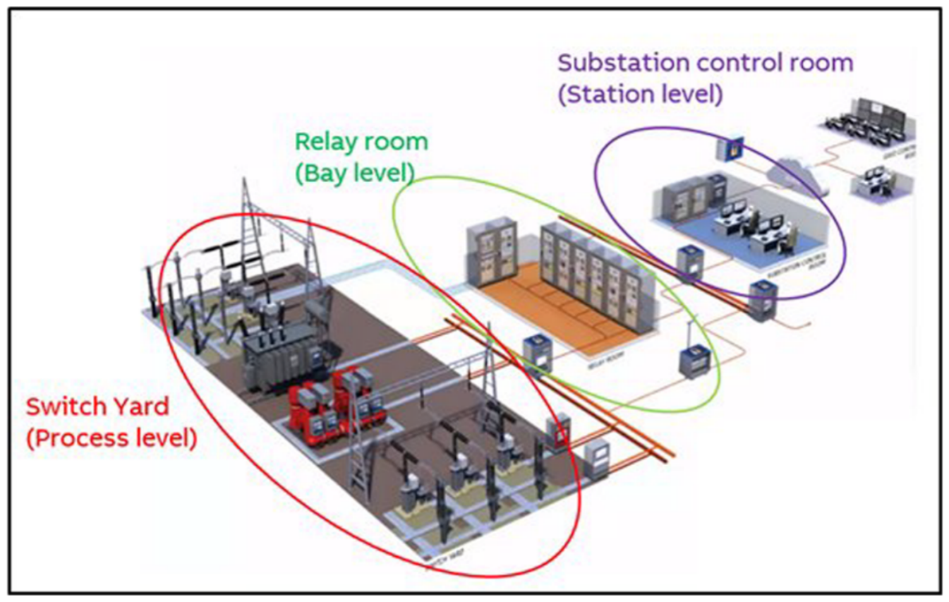
Figure 2.
Typical OPC DA architecture (client via COM/DCOM to local/remote OPC server with cache and device), adapted from ([23], Figure 2–6).
Figure 2.
Typical OPC DA architecture (client via COM/DCOM to local/remote OPC server with cache and device), adapted from ([23], Figure 2–6).
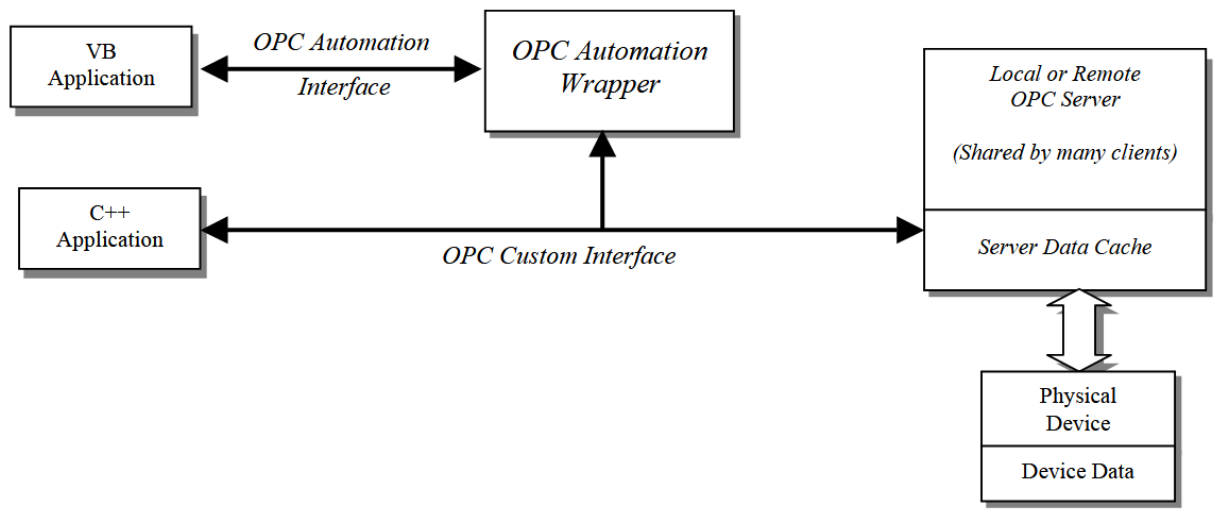
Figure 3.
OPC UA integrated client–server and PubSub models, adapted from ([27], Figure 8).
Figure 3.
OPC UA integrated client–server and PubSub models, adapted from ([27], Figure 8).
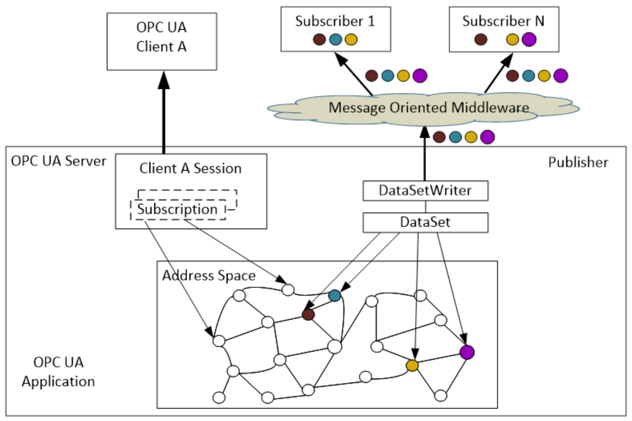
Figure 4.
Overview of the subsea cable routing to the interconnected offshore facilities at Utsirahøyden. Adapted from [35].
Figure 4.
Overview of the subsea cable routing to the interconnected offshore facilities at Utsirahøyden. Adapted from [35].
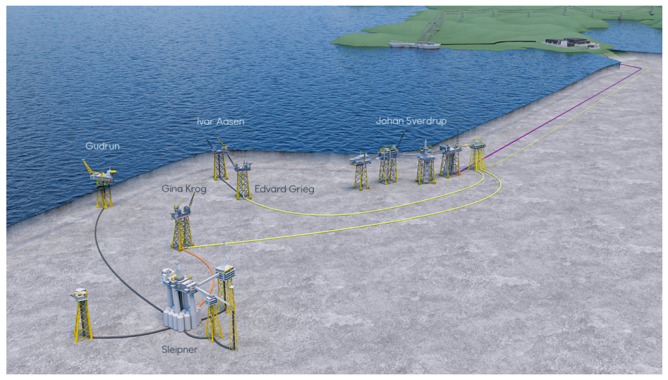
Figure 5.
Timeline of prominent cyberattacks targeting energy infrastructure in Ukraine (2015–2024).
Figure 5.
Timeline of prominent cyberattacks targeting energy infrastructure in Ukraine (2015–2024).
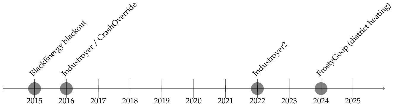
Figure 6.
Example topology for a modern substation, adapted from ([13], Figure 3).
Figure 6.
Example topology for a modern substation, adapted from ([13], Figure 3).
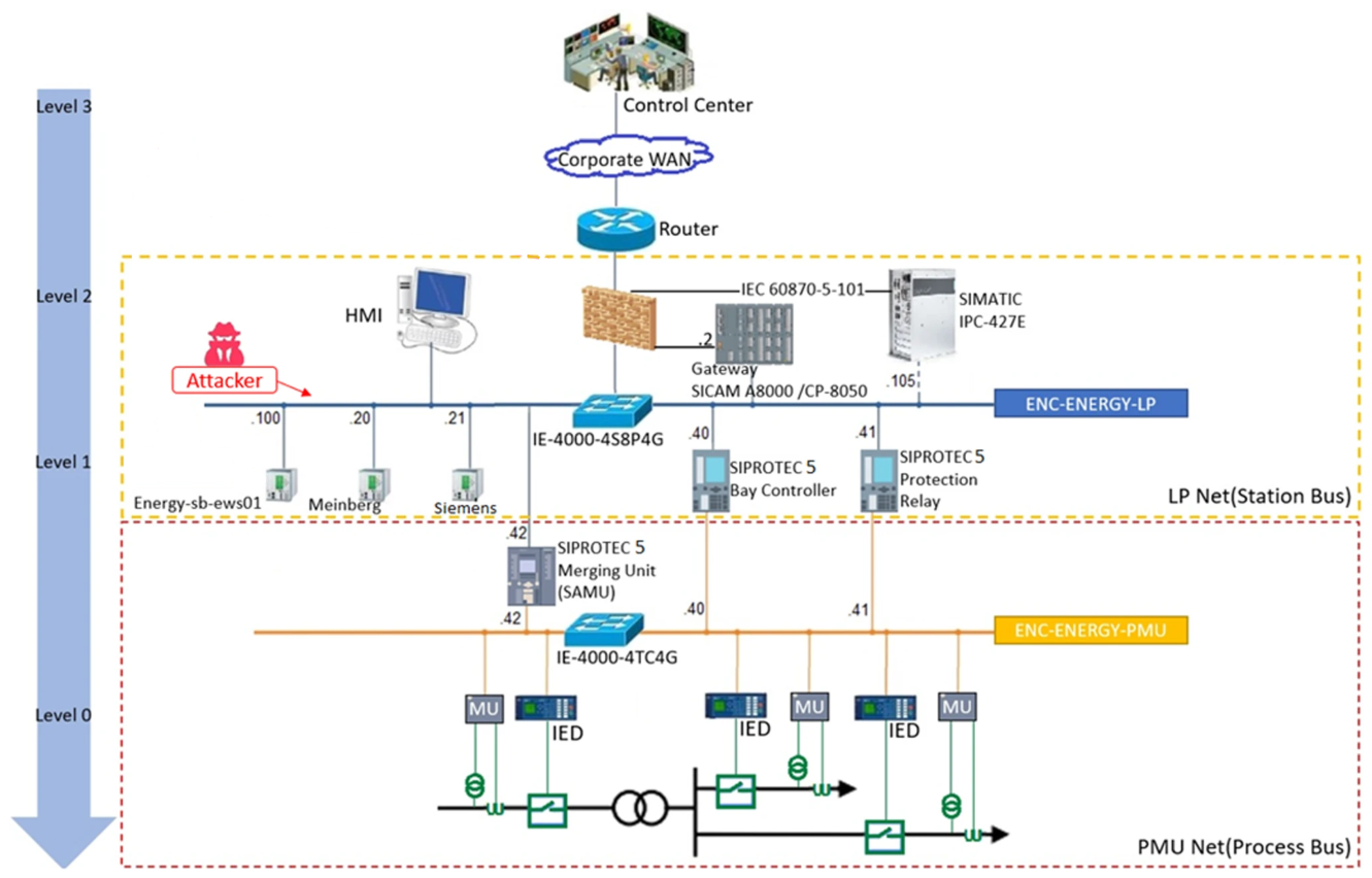
Figure 7.
GNS3 network topology.
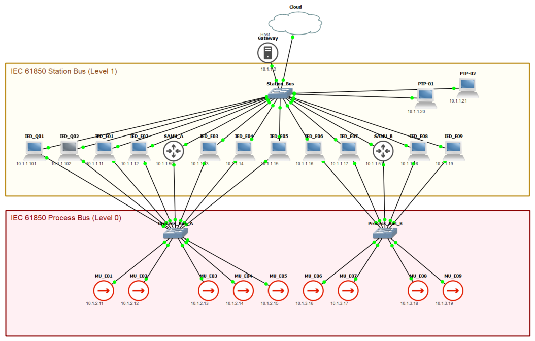
Figure 8.
Schematic circuit diagram.
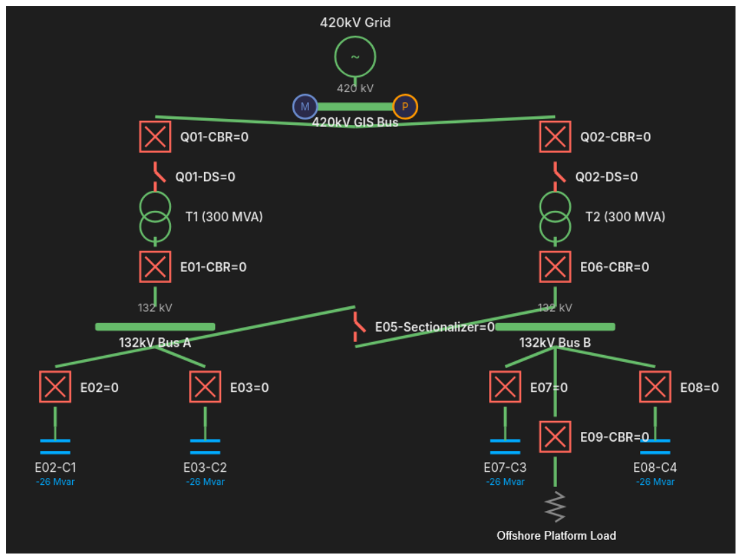
Figure 9.
Overview of a high-voltage circuit breaker. The external view (a) shows the bushings and control cabinet, while the internal schematic (b) details the fixed and moving contacts used for arc extinction. Adapted from [56].
Figure 9.
Overview of a high-voltage circuit breaker. The external view (a) shows the bushings and control cabinet, while the internal schematic (b) details the fixed and moving contacts used for arc extinction. Adapted from [56].
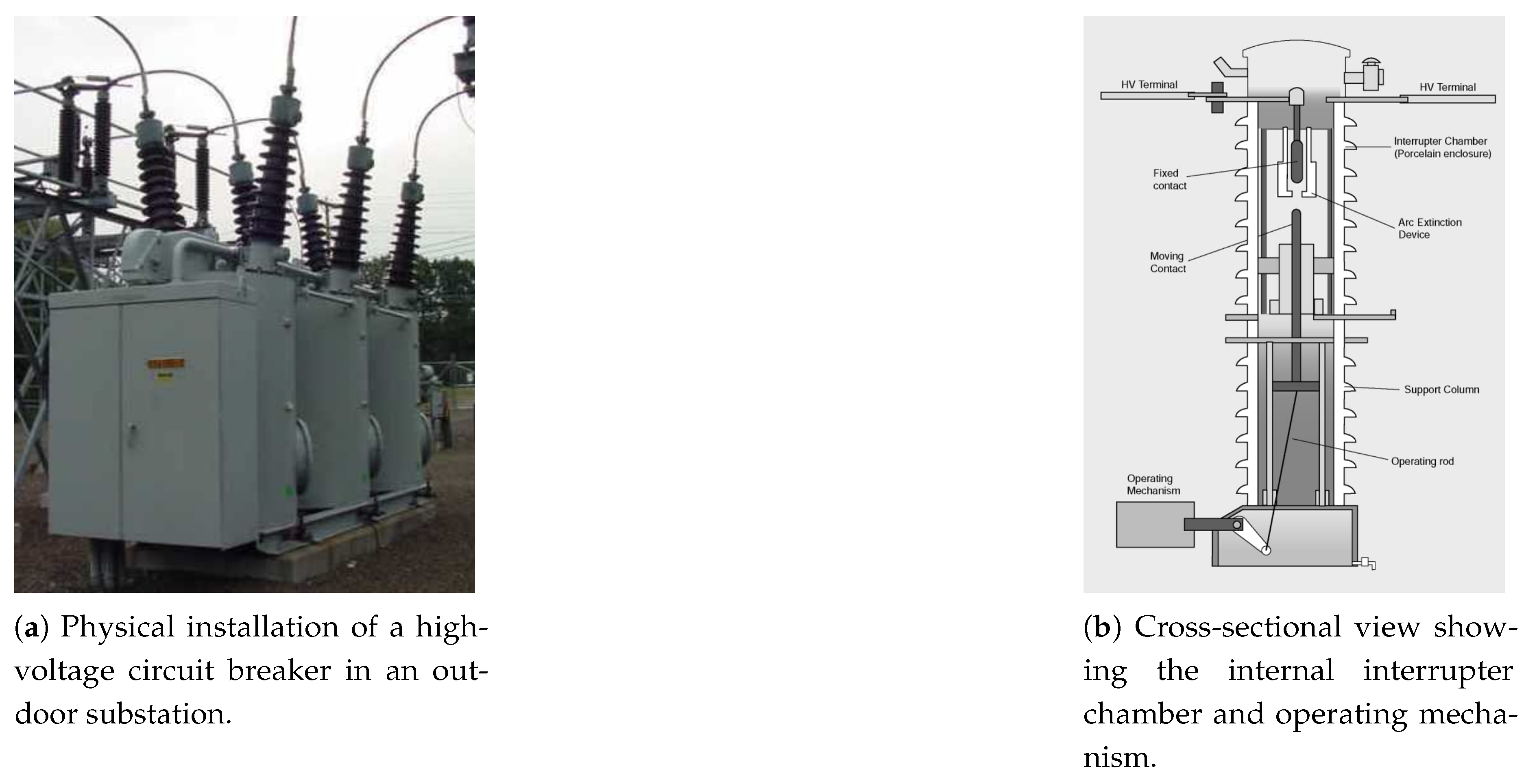
Figure 10.
An open disconnector showing the visible isolation gap. Adapted from [57].
Figure 10.
An open disconnector showing the visible isolation gap. Adapted from [57].
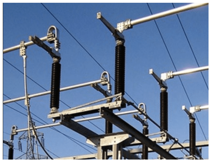

Table 1.
2015 Ukraine power grid attack (BlackEnergy3).
| Step | Description |
|---|---|
| 1: Initial Access |
|
| 2: Reconnaissance |
|
| 3: Data Exfiltration |
|
| 4: Weaponization |
|
| 5: Local Access | |
| 6: Delivery |
|
| 7: Exploitation |
|
| 8: Actions |
|
| 9: Sabotage |
|
Table 2.
Kill Chain.
| Step | Description |
|---|---|
| 1: Initial Access | The attacker begins by collecting publicly available information. Concession applications submitted to Norwegian Water Resources and Energy Directorate (NVE) and a various technical public reports provide enough context about planned infrastructure and facility specifications to form a plausible hypothesis for an attack and identify critical dependencies. |
| 2: Reconnaissance | Based on the OSINT in Step 1, the attacker narrows the scenario toward the power supply architecture. This phase uses public information from the Transmission System Operator (TSO) and the offshore operators. This combined with a review of typical substation and HVDC vendor ecosystems and prior literature on electrical infrastructure cyberattacks, to identify likely technologies and high-level architectures in scope. |
| 3: Data Exfiltration | In this scenario, no information is taken from inside the target system. The work is based entirely on publicly available sources, and the collected OSINT is consolidated and organized in the attacker’s development environment. Publicly documented attack patterns, such as prior Sandworm reporting and structured mappings like MITRE[58], are then used to shape the assessment. This leads to a focus on substations and switching functions as a plausible target area. |
| 4: Weaponization | A substation simulator is developed and used as a controlled test environment. This allows development, verification, and refinement of the malware logic without requiring access to real equipment during the development phase. |
| 5: Local Access | The scenario assumes local access is needed to reach the operational environment. The attacker could pursue access at the offshore receiving facility or at the onshore grid connection point. |
| 6: Delivery | The malicious capability is introduced into the relevant OT environment by connecting a compromised host to the appropriate subnet. The payload may execute immediately or be configured to trigger at a later time. |
| 7: Exploitation | Before acting, the malware performs basic validation such as checking system state and timing conditions and ensuring it targets the intended device. It then attempts unauthorized use of legitimate substation control functionality to initiate the planned switching action. |
| 8: Actions | The attacker’s immediate objective is to open a breaker under unfavorable operating conditions. In a worst-case scenario, an incorrect switching action can create severe operational disturbance and may contribute to equipment stress or damage risk, depending on whether the system is energized or not. |
| 9: Sabotage | The overall impact is intended to be loss of power, possible equipment damage, and operational uncertainty. Persistence can be achieved through repeated triggering over time, potentially spaced out to complicate detection and response. |
Disclaimer/Publisher’s Note: The statements, opinions and data contained in all publications are solely those of the individual author(s) and contributor(s) and not of MDPI and/or the editor(s). MDPI and/or the editor(s) disclaim responsibility for any injury to people or property resulting from any ideas, methods, instructions or products referred to in the content. |
© 2026 by the authors. Licensee MDPI, Basel, Switzerland. This article is an open access article distributed under the terms and conditions of the Creative Commons Attribution (CC BY) license (http://creativecommons.org/licenses/by/4.0/).
Copyright: This open access article is published under a Creative Commons CC BY 4.0 license, which permit the free download, distribution, and reuse, provided that the author and preprint are cited in any reuse.


