

Submitted:
23 May 2026
Posted:
26 May 2026
You are already at the latest version
Abstract
Conventional selfie sticks, typically limited to a maximum reach of 1.5 m, are unable to effectively capture large group photographs or wide-background scenes, frequently resulting in restricted framing and facial cropping. This work presents the design, implementation, and experimental validation of a Bluetooth-controlled mobile robot with five degrees of freedom capable of capturing photographs at distances of up to 10 m using a dual-smartphone master–slave architecture. The proposed system integrates an Arduino Nano microcontroller, an L298N motor driver, three SG90 servo motors, an HC-05 Bluetooth module, and a rechargeable Li-Ion battery mounted on a four-wheel chassis. A master smartphone remotely controls both the mobile platform and the articulated camera arm, while a slave smartphone mounted on the arm captures images through its high-resolution rear camera with real-time video streaming. Experimental evaluations demonstrated 100% command transmission success at distances up to 10 m, automatic emergency stopping within 100–110 ms after Bluetooth disconnection, accurate face centering with minimal servo adjustments, and approximately 45 min of battery autonomy. The proposed open-source, low-cost teleoperated platform extends the effective photographic range from 1.5 m to 10 m while providing potentially improved photographic quality due to rear-camera imaging characteristics and full remote framing control compared with conventional selfie accessories.
Keywords:
selfie robot
; Bluetooth control
; master-slave architecture
; Arduino
; five-DOF robotic arm
1. Introduction
When a user wishes to capture a self-portrait or group photograph (selfie) with their smartphone, they hold the device in their hand, activate the front-camera mode, and extend their arm as far as possible to widen the capture angle. However, the arm’s reach is frequently insufficient to frame the entire scene, especially in large groups or when part of the body is excluded from the frame. As a partial solution, selfie sticks emerged, whose maximum commercial length does not exceed 1.5 m; although this extension notably improves the photographed angle, it remains insufficient when the group is large or when the scene requires significant angular aperture, such as an extensive landscape, a mountain, or a wide visual composition.
Recent advances in robotics and automation have driven the development of intelligent embedded systems for human–technology interaction, integrating sensors, actuators, and distributed control architectures into compact programmable platforms. In particular, the convergence of open-source microcontroller ecosystems and low-cost wireless communication modules has substantially broadened access to mobile robotics research, particularly at institutions in developing countries [1].
To address this limitation, this work introduces a low-cost teleoperated robotic platform based on the Arduino Nano microcontroller, operating under a master–slave communication architecture. A primary smartphone serves as the master controller, coordinating chassis locomotion and photographic operations, while a secondary device mounted on the articulated arm functions as the dedicated image capture unit. This architecture enables the operator to remain within the photographed group while the platform, stationed up to 10 m away, acquires images via the high-resolution rear camera of the slave device.
A key technical differentiating aspect of this proposal is the use of the rear camera of the slave smartphone, technically known as the primary camera, instead of the front-facing camera conventionally employed in selfies. The rear camera provides superior optical characteristics, higher resolution, wider aperture, optical image stabilization (OIS), and enhanced low-light sensitivity, as established in the computational photography literature [2], yielding measurably sharper photographic output.
The proposed platform may support future educational and research applications in embedded robotics and computational imaging, integrating knowledge from electronics, programming, and mechanical design.
The objective of this work is to design, implement, and experimentally validate a five-degree-of-freedom Bluetooth-controlled selfie robot integrating a three-servo articulated arm and a master-slave dual-smartphone architecture, capable of capturing group and wide-panorama photographs at up to 10 m distance with reliable command delivery, precise framing, and safe autonomous operation.
2. Literature Review and Background
2.1. Cultural and Technological Evolution of the Selfie
The self-portrait photograph predates the digital era, with early practitioners using mirrors and fixed-point setups as compositional tools. Tifentale [3] argues that the term ‘selfie’ should be applied exclusively to the post-2010 phenomenon of self-portrait images enabled by smartphones and shared on networks. Martín Prada [4] frames the selfie as a social authentication device: the arm holding the camera functions as a first-person witness, validating the subject’s presence in a given context.
2.2. Selfie Sticks and Their Limitations
The selfie stick, commercialized globally from 2014, extends the effective capture distance to approximately 80–150 cm but does not resolve fundamental limitations of stability, angular adjustment, or depth in group photographs. Tifentale and Manovich [5] demonstrated through computational analysis of large selfie datasets that ergonomic device constraints systematically bias photographic composition toward ascending camera angles and facial cropping artifacts, revealing structural limitations that no handheld accessory can overcome.
Building on this evidence, Chu and Tu [6] reviewed state-of-the-art selfie interaction systems and identified physical reach as the primary constraint motivating more advanced capture platforms, documenting that existing accessories remain insufficient for wide-group and wide-background scenarios. A teleoperated platform with 10 m operational range and five-degree-of-freedom control directly addresses these documented limitations.
2.3. Arduino-Based Robotic Platforms
Arduino microcontrollers have been widely adopted as the control core for educational and low-cost research robotic platforms, thanks to their open-source architecture, broad peripheral support, and active developer community [1]. The Arduino Nano, employed in this work, combines the ATmega328P processor with a compact form factor of 18 × 45 mm, sufficient for the sensing and actuation requirements of the robot.
2.4. Bluetooth Communication in Embedded Systems
The HC-05 module implements the Bluetooth 2.0+EDR standard in the 2.4 GHz ISM band and provides a UART interface configurable from 9600 to 460,800 bps, enabling direct integration with embedded controllers such as the Arduino Nano. Its available bandwidth substantially exceeds the requirements of low-rate ASCII command transmission, making it suitable for reliable short-range real-time robotic teleoperation and safety signaling in indoor environments, as demonstrated by Murad et al. [7] in the implementation of an Arduino-based wireless robot control system using the HC-06 Bluetooth module of the same family. Ahmmed et al. [8] demonstrated reliable Bluetooth-based control for Arduino mobile robots, emphasizing the importance of robust communication for safe operation.
2.5. L298N Motor Driver and DC Control
The L298N is a dual H-bridge capable of 2 A per channel with a supply voltage of 5–46 V [9]. Its adoption in educational robotics stems from the straightforward combination of PWM signals on the enable pins for speed modulation with logic-level inputs for direction control, a scheme that inherently produces smooth directional transitions proportional to the PWM duty cycle, as specified in the manufacturer’s application notes [9].
2.6. Position Control with Servo Motors
Servo motors operate through 50 Hz PWM control signals, where pulse widths between 1 and 2 ms correspond to angular positions from 0° to 180°. The Arduino Servo library simplifies multi-channel servo management through hardware-interrupt-based timing control. To improve positioning stability, the present design isolates the motor power supply from the servo control circuitry, reducing signal jitter and enhancing angular precision. The torque safety factor methodology for servo-driven manipulators applied in Section 3.3.1 follows the approach of Nasir et al. [10].
2.7. Mobile Robotics for Photography
Ikpeze et al. [11] developed a low-cost Raspberry Pi-based mobile robot with smartphone teleoperation, live video streaming, and image capture capabilities. Their subsystem-based architecture, integrating locomotion, camera control, and wireless communication, serves as a useful reference for the present work, which adopts a similar structure while employing Bluetooth-based short-range control and a rear smartphone camera for improved image quality.
Liu et al. [12] developed a low-cost UAV equipped with a 3-axis stabilized gimbal for autonomous real-time visual tracking using IMU-based control and KCF target tracking. Unlike this airborne autonomous system, the proposed work focuses on ground teleoperation, combining 2-DOF mobile locomotion with a 3-DOF articulated servo arm to enable manual camera positioning and remote photographic framing within a 10 m operational range using a lower-cost architecture.
Alatise and Hancke [13] provide a comprehensive overview of the challenges of autonomous mobile robotics, including reliable wireless communication and sensor fusion, which serve as a reference framework for the design decisions adopted in this work.
2.8. Mobile Control Applications
The ‘Arduino Bluetooth Controller’ family of applications transmits commands in single-character ASCII encoding via Bluetooth SPP. Singh and Singh [14] validated the Bluetooth ASCII paradigm for multi-DOF robotic arm control using Arduino, demonstrating its sufficiency for coordinating multiple discrete servo actuators with sub-frame latency. For video streaming, the IP Webcam application transmits the MJPEG stream from the rear camera of the slave smartphone over the local Wi-Fi network, with typical latencies of 100–300 ms, sufficient for interactive photographic framing.
2.9. Extensions with Deep Learning for Smart Photography
Vega-Huerta et al. [15] demonstrated that CNN ensembles (EfficientNet + VGG-19) classify dermatoscopic images with 92.85% accuracy, illustrating the applicability of deep learning in the Peruvian context. Vega-Huerta et al. [16] extended this approach to Alzheimer’s diagnosis via magnetic resonance images with accuracy above 91.83%, consolidating the research line of the YACHAY-UNMSM group in medical computer vision. Zhang et al. [17] proposed multi-task cascaded convolutional networks (MTCNN) achieving simultaneous face detection and alignment with greater robustness to scale and illumination variations, constituting the most technically suitable reference for future integration in the present robot.
2.10. Safety Mechanisms in Mobile Robots
The IEC 61508 standard prescribes watchdog timers as a primary mitigation for software failures in embedded controllers [18]. Chin et al. [19] demonstrated that an autonomous stopping latency below 200 ms is sufficient to prevent collisions at typical indoor robot speeds (0.3 m/s). The 100 ms implemented in the present firmware satisfies this criterion with a 2× safety margin.
3. Materials and Methods
3.1. General System Architecture
The selfie robot was developed on an open-source platform capable of positioning a mobile device for image capture. The architecture follows a master–slave paradigm: the user’s smartphone acts as the master, emitting commands via Bluetooth SPP, while the Arduino Nano acts as the slave, interpreting the data stream and dispatching PWM signals to the actuators. A second smartphone, attached to the robot, runs the IP Webcam application for real-time video streaming. The user visualizes in real time, on a split screen, what the rear camera of the slave smartphone is capturing; when the framing is optimal, the capture is executed remotely from the master. Figure 1 illustrates the communication architecture of the system with its three main subsystems.
3.2. Hardware Components and Specifications
The experimental prototype was assembled from low-cost electronic and mechanical components selected on the basis of integration compatibility, technical specification compliance, and commercial availability in the domestic market. Table 1 summarizes the main components with their key technical specifications.
3.2.1. Power Budget Analysis
The total system current demand is estimated by summing subsystem draws [20]:
where n_m = 4 motors (I_m = 200 mA each), n_s = 3 servos (I_s = 50 mA each), I_ctrl = 50 mA (Arduino Nano), I_BT = 40 mA (HC-05), I_str = 300 mA (slave smartphone streaming). The weighted average under the mixed-use protocol is I_avg = 870 mA. Peak power and theoretical battery life:
I_total = (n_m × I_m) + (n_s × I_s) + I_ctrl + I_BT + I_str (1)
P_max = V_bat × I_peak = 7.4 V × 1.24 A = 9.2 W (2)
t_bat = Q / I_avg = 2000 mAh / 870 mA ≈ 2.3 h (3)
The measured autonomy of 45 min is shorter because I_str (34% of I_total) is absent from conventional mobile robot power models [20].
3.3. Mechanical Design and Degrees of Freedom
The system was integrated onto a four-wheel ABS plastic chassis of approximately 200 × 150 × 60 mm. The motors were connected to the L298N to enable forward, reverse, and differential steering. The three-segment articulated arm is mounted on the central cover: the first segment is a servo-driven turntable (azimuth, 0°–180°); the second is a pivoting joint (elevation, 0°–180°); and the third tilts the smartphone holder (tilt, 0°–180°). This 3-DOF arm, combined with the 2 translational DOF of the chassis, provides a total of five controllable degrees of freedom. The system electronics are powered by an integrated rechargeable lithium battery.
Figure 2 shows the design prior to construction (4WD chassis layout, three-segment articulated arm, and slave smartphone holder). Figure 3 shows the constructed prototype, featuring the 4WD platform, the three-SG90-servo articulated arm, the slave smartphone holder, and the integrated electronics (Arduino Nano, HC-05, L298N, Li-Ion battery).
3.3.1. Servo Torque Verification
The required holding torque at each joint is:
where M_load is the total distal mass (kg), g = 9.81 m/s2, and L_eff is the lever arm (m). Joint 3 (tilt, M = 0.22 kg, L = 0.04 m): T_tilt = 0.086 N·m (0.88 kg·cm). Joint 2 (elevation, M = 0.235 kg, L = 0.06 m): T_elev = 0.138 N·m (1.41 kg·cm). Joint 1 (azimuth): T_dyn = 0.026 N·m (0.27 kg·cm). Safety factor at the critical joint: SF = 1.8 / 1.41 = 1.28 [10]. MG90S servos (T_rated = 2.2 kg·cm, SF = 1.44) are recommended for smartphones exceeding 0.25 kg.
T_req = M_load × g × L_eff (4)
The slave smartphone holder at the end of the arm was dimensioned for devices up to 6.7 inches in diagonal, keeping the rear camera oriented toward the photographed subject. Table 2 presents the five degrees of freedom of the system.
3.4. Electronic Circuit Design
The Arduino Nano microcontroller serves as the central processing unit of the embedded control architecture. Its digital output pins 10, 9, 6, and 5 generate PWM signals driving the IN1–IN4 lines of the L298N H-bridge, enabling continuous speed modulation. The three servo channels connect to pins 4, 7, and 8, managed by the Arduino Servo library. The HC-05 Bluetooth module interfaces through pins 3 and 2 via a SoftwareSerial port configured at 9600 bps. Decoupling capacitors (100 nF ceramic in parallel with 1000 µF electrolytic) were incorporated at the L298N supply input to attenuate inductive switching transients, protecting the servo signal ground reference. Table 3 shows the complete connection map of the system, detailing the Arduino Nano pin assignments, power supply lines, and peripheral modules.
3.4.1. PWM Voltage, Tractive Force, and Displacement Speed
The effective motor terminal voltage as a function of PWM duty cycle D [9]:
where V_supply = 7.4 V and V_drop_L298N = 1.4 V. Theoretical no-load speed (TT motor rated 150 rpm at 5 V, wheel radius r = 33 mm):
V_motor = D × (V_supply − V_drop_L298N) = D × 6.0 V (5)
v_max = (n × 2π × r) / 60 = (180 × 2π × 0.033) / 60 ≈ 0.62 m/s (6)
Under mixed load conditions, the experimentally measured operating speed was v_op = 0.30 m/s, consistent with the 50% velocity reduction typically observed under load for TT motors at this gear ratio.
3.5. Embedded Firmware Design
3.5.1. Global Declarations and Initialization
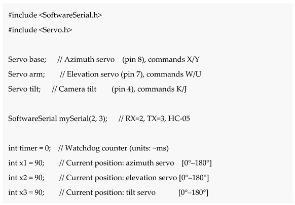
The embedded firmware was implemented in the Arduino IDE environment using C++. Two core libraries underpin the control architecture: SoftwareSerial manages Bluetooth serial communication, while the Servo library handles angular positioning. Three Servo objects (base, arm, tilt) and their corresponding state variables (x1, x2, x3) are initialized to 90°, establishing the mechanical neutral configuration at power-on.
Code Fragment 1. Library inclusion and global variable declarations of the firmware.
Bluetooth command throughput. With 8N1 UART framing at 9600 baud:
Each command is a single ASCII byte, yielding a minimum inter-command period of 1.04 ms; Gupta et al. [21] measured Bluetooth control latencies of 38–72 ms (mean = 55 ms) on a comparable single-byte ASCII platform, confirming that link overhead remains negligible relative to actuator response time.
3.5.2. Setup() Function
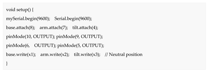
In the setup() function, the serial ports are initialized at 9600 bps, the servos are attached to their pins, the four L298N control pins are configured as outputs, and the servos receive the 90° neutral position.
Code Fragment 2. setup() function: peripheral initialization and neutral position of the three servo motors.
3.5.3. Main Loop and Watchdog Mechanism
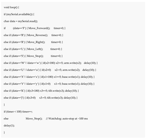
The loop() function reads the Bluetooth serial buffer, dispatches the received byte, and manages the counter. Each iteration lasts ~1 ms (due to the final delay(1)). If no movement command arrives within 100 ms (timer > 100), Mover_Stop() is invoked automatically, implementing the dead-man switch.
Code Fragment 3. loop() function with Bluetooth command dispatch and 100 ms watchdog mechanism.
3.5.4. Chassis Actuation Functions
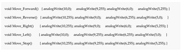
The four movement functions control the L298N via PWM signals. The Move_Stop() function drives all pins HIGH to activate the driver’s electric brake.
Code Fragment 4. Chassis movement functions via PWM control of the L298N driver.
3.6. Bluetooth Command Vocabulary
Table 4 details the complete vocabulary of eleven ASCII commands implemented in the firmware, covering the five degrees of freedom of the system.
3.7. Mobile Application, Operation Protocol, and Remote Photographic Control
This configuration enables the operator, included in the photographed group, to navigate the platform to the desired distance (up to 10 m), adjust the three arm axes until optimal framing is confirmed on the master’s live preview, and trigger remote image capture upon achieving the desired composition. Figure 4 illustrates the split-screen interface of the master smartphone during system operation.
3.7.1. Digital Zoom, Focus, and Sensitivity
The IP Webcam application exposes the Android Camera2 API, enabling remote control of zoom, focus, and exposure. The minimum resolvable object diameter at distance d and zoom factor Z is:
D_min = (d × pixel_pitch) ∕ (f_eff × Z) (7)
For a typical rear camera (λpixel = 1.4 μm, f_eff = 3.6 mm) at d = 10 m and Z = 1: D_min = 3.9 mm, sufficient to resolve facial features. ISO sensitivity spans 100–3200 (+1 EV per doubling, −3 dB SNR cost), enabling photography at ≤3 lux (ISO 800). Continuous auto-focus (FOCUS_MODE_CONTINUOUS_VIDEO) and EV compensation of ±2 EV are also remotely controllable. Table 5 presents the seven-step sequential operation protocol.
3.8. Experimental Protocol
Field tests were conducted at UNMSM facilities following the four-trial protocol below:
Trial 1 – Bluetooth range: robot operation at 1, 3, 5, 7, and 10 m in an open corridor; successful command delivery rate and command latency were recorded (n = 5 trials per distance, 50 commands per trial).
Trial 2 – Framing precision: human subject at 5 m; the number of servo steps required to center the face in the viewer was measured over ten repetitions.
Trial 3 – Watchdog (dead-man switch): deliberate interruption of the Bluetooth link during active movement; time to motor stop was measured over five trials.
Trial 4 – Battery autonomy: continuous driving on a figure-of-eight trajectory with mixed load (60% driving, 30% servo adjustment, 10% idle) until battery protection disconnect.
4. Results
4.1. Bluetooth Communication Range
Command delivery achieved 100% success at all evaluated distances up to 7 m. At the maximum tested range of 10 m, full command reception was maintained under line-of-sight conditions, with a marginal increase in command latency. No packet loss was recorded at any distance, consistent with the Class 2 propagation characteristics of the HC-05 module and the latency measurements of Gupta et al. [21]. Table 6 summarizes the quantitative results.
4.2. Camera Positioning on Three Axes
Experimental evaluation of the three servo axes demonstrated consistent and repeatable angular positioning across all tested configurations. The 5° angular resolution per command byte supported fine-grain adjustments: between 2 and 6 discrete steps (10°–30° total angular correction) proved sufficient to center a human face within the live framing viewport at 5 m. Furthermore, the limit logic reliably intercepted all out-of-range commands without inducing mechanical damage, and the 90° initialization ensured a reproducible forward-facing configuration at every power-on cycle.
4.3. Locomotion Watchdog
Systematic evaluation of the locomotion watchdog confirmed complete motor arrest within 100–110 ms across all five repeated trials, satisfying the sub-200 ms collision-prevention criterion established by Chin et al. [19]. Consequently, at the nominal operating speed of 0.3 m/s, the platform travels no more than 3.3 cm from the moment of signal loss to complete halt, a residual displacement sufficient to prevent contact with nearby individuals.
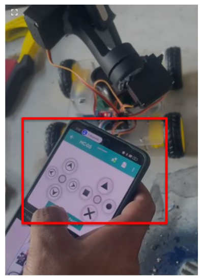
Figure 5.
Selfie Robot during field tests.
4.4. Battery Autonomy
The 7.4 V / 2000 mAh battery sustained approximately 45 minutes of continuous mixed operation (~60% driving, ~30% servo adjustment, ~10% idle). The estimated average current consumption was 800–900 mA, consistent with the sum of individual consumptions: four DC motors (~200 mA each), three servos in motion (~50 mA each), Arduino Nano + HC-05 (~50 mA), and slave smartphone streaming (~300 mA). A 3000 mAh battery projects ~67 minutes of autonomy, adequate for extended photo sessions.
Figure 6 shows the Arduino Bluetooth Controller application interface with the HC-05 module connected and the command panel active.
4.5. Performance Comparison
Table 7 summarizes the performance comparison between the proposed system and various reference solutions.
The compared systems address different operational objectives; the table provides a qualitative functional comparison only.
5. Discussion
The experimental results validate the stated objective: the developed prototype demonstrates that a low-cost Arduino Nano-based system can remotely control chassis locomotion and smartphone photographic functions via Bluetooth while sustaining 100% command delivery with low perceptible communication latency across the full 10 m operational range.
Relative to the Raspberry Pi-based smartphone-controlled robot of Ikpeze et al. [11], the present system offers two differential advantages: (a) the 3-DOF articulated arm enables angular camera orientation without chassis repositioning; and (b) the total cost is two to four times lower than the equivalent Raspberry Pi platform. The primary trade-off is the Bluetooth-limited range (10 m versus Wi-Fi), addressable in future iterations with an ESP32 module.
Compared with the UAV-mounted gimbal of Liu et al. [12], both platforms address fundamentally different objectives: whereas that system targets autonomous aerial tracking through closed-loop BLDC stabilization and computer-vision algorithms, the proposed robot operates as a ground-based teleoperated platform that prioritizes deliberate photographic composition through integrated translational mobility, 3-DOF articulated orientation, real-time video streaming, and full remote photographic control at a fraction of the cost.
A relevant contribution of the proposed platform is the integration of the smartphone rear camera as the primary imaging sensor, enabling remote access to advanced photographic functions such as zoom, exposure adjustment, burst mode, and HDR capture. This level of remote photographic interaction is not commonly reported in related low-cost teleoperated robotic platforms for group photography applications.
Regarding operational safety, the implemented 100 ms watchdog mechanism satisfies the sub-200 ms recommendation reported by Chin et al. [19]. Furthermore, the low-latency behavior observed in the Bluetooth communication scheme is consistent with the findings of Gupta et al. [21] for comparable single-byte ASCII transmission architectures.
The study presents several limitations. First, communication latency in Trial 1 was estimated observationally rather than instrumentally measured. Second, the watchdog timer resets only during chassis-control commands, which may produce unintended stops during arm-only adjustments. Third, image framing remains fully manual. Future work will address these limitations through instrumented latency analysis, firmware optimization, integration of the MTCNN facial detector [17], voice-command interaction, and Wi-Fi-based connectivity.
6. Conclusions
This article presented the design, implementation, and experimental validation of a Bluetooth-controlled five-degree-of-freedom selfie robot based on the Arduino Nano microcontroller platform. The main conclusions are as follows:
(1) A functional five-degree-of-freedom robotic prototype was successfully developed and experimentally validated. The system maintained stable wireless communication throughout the 0–10 m operational range, achieving 100% command delivery with responsive teleoperation performance and approximately 45 min of battery autonomy under mixed operating conditions.
(2) The proposed platform enables remote capture of group photographs and wide-background scenes at distances significantly greater than those achievable with conventional selfie accessories. The use of the rear smartphone camera as the primary imaging sensor provides improved photographic quality while enabling remote access to advanced camera functions, including zoom, exposure adjustment, burst mode, and HDR capture.
(3) The implemented eleven-command Bluetooth communication protocol enabled reliable five-degree-of-freedom teleoperation across the complete operational range. In addition, the integrated 100 ms watchdog mechanism satisfied the sub-200 ms safety criterion reported in previous studies, contributing to safe remote platform operation. The split-screen interface combining IP Webcam and Arduino Bluetooth Controller also provided intuitive real-time teleoperation without requiring specialized technical expertise.
(4) The modular architecture of the proposed system facilitates future extensions, including Wi-Fi-based long-range teleoperation, voice-command interaction, and autonomous visual tracking. In particular, the integration of convolutional neural network-based facial detection methods, such as the MTCNN detector, represents a promising direction for semi-autonomous framing and subject tracking.
Author Contributions
Conceptualization, H.V. and P.D.; methodology, H.V., P.D., P.Q. and M.C.; software, P.Q. and L.G.; validation, F.L. and O.B.; formal analysis, A.C., L.G. and J.C.; investigation, P.Q., A.C.F. and J.P.; resources, H.V., A.L. and P.D.; data curation, L.G. and A.L..; writing—original draft, H.V., P.D., P.Q. and M.C.; writing—review and editing, M.N., F.L. and J.P.; supervision, H.V.; funding acquisition, H.V. All authors have read and agreed to the published version of the manuscript.
Funding
This research was supported by the Universidad Nacional Mayor de San Marcos – RR N° 010238-2024-R/UNMSM and project number C24200421i.
Conflicts of Interest
The authors declare no conflicts of interest. The funders had no role in the design of the study or in the decision to publish the results.
References
- D. Betancur-Vásquez, M. Mejia-Herrera, and J. S. Botero-Valencia, “Open source and open hardware mobile robot for developing applications in education and research,” HardwareX, vol. 10, Art. no. e00217, 2021. [CrossRef]
- S. W. Hasinoff et al., “Burst photography for high dynamic range and low-light imaging on mobile cameras,” ACM Trans. Graph., vol. 35, no. 6, Art. no. 192, 2016. [CrossRef]
- A. Tifentale, “The selfie: More and less than a self-portrait,” in The Routledge Companion to Photography and Visual Culture, M. Neumüller, Ed. New York, NY, USA: Routledge, 2018, pp. 44–58. [CrossRef]
- J. Martín Prada, El ver y las imágenes en el tiempo de Internet. Madrid, Spain: Akal, 2018, ISBN 978-84-460-4605-9.
- A. Tifentale and L. Manovich, “Selfiecity: Exploring photography and self-fashioning in social media,” in Postdigital Aesthetics, D. M. Berry and M. Dieter, Eds. London, UK: Palgrave Macmillan, 2015, pp. 109–122. [CrossRef]
- S. Chu and H. Tu, “Interaction techniques for taking selfies: A review,” Int. J. Hum.-Comput. Interact., vol. 42, no. 2, pp. 809–829, Jun. 2025. [CrossRef]
- A. Murad, O. Bayat, and H. M. Marhoon, “Implementation of rover tank firefighting robot for closed areas based on Arduino microcontroller,” Indonesian J. Electr. Eng. Comput. Sci., vol. 21, no. 1, pp. 56–63, 2021. [CrossRef]
- F. Ahmmed, A. Rahman, A. Islam, A. Alaly, S. Mehnaj, P. Saha, and T. Hossain, “Arduino-controlled multi-function robot with Bluetooth and nRF24L01+ communication,” Int. J. Robot. Control Syst., vol. 4, no. 3, pp. 1353–1381, 2024. [CrossRef]
- STMicroelectronics, “L298 Dual Full-Bridge Driver,” Datasheet DS0218 Rev. 5, Oct. 2023. [Online]. Available: https://www.st.com/resource/en/datasheet/l298.pdf.
- A. N. K. Nasir, M. A. Ahmad, and M. F. Mohammed, “Comparison of control strategies for a two-link flexible robot manipulator driven by servo motors,” in Proc. 2nd Int. Conf. Comput. Intell. Commun. Syst. Netw. (CICSyN), Dalian, China, 2010, pp. 93–98. [CrossRef]
- O. Ikpeze, T. Ejidokun, and M. Onibonoje, “Smartphone control mobile robot for education and research,” J. Robot., vol. 2022, Art. no. 5178629, 2022. [CrossRef]
- X. Liu, Y. Yang, C. Ma, J. Li, and S. Zhang, “Real-time visual tracking of moving targets using a low-cost unmanned aerial vehicle with a 3-axis stabilized gimbal system,” Appl. Sci., vol. 10, no. 15, Art. no. 5064, 2020. [CrossRef]
- M. B. Alatise and G. P. Hancke, “A review on challenges of autonomous mobile robot and sensor fusion methods,” IEEE Access, vol. 8, pp. 39830–39846, 2020. [CrossRef]
- A. Singh and V. Singh, “Android Bluetooth-controlled multi-degree robotic arm using Arduino,” J. Phys. Conf. Ser., vol. 1950, Art. no. 012062, 2021. [CrossRef]
- H. Vega-Huerta et al., “Convolutional neural networks on assembling classification models to detect melanoma skin cancer,” Int. J. Online Biomed. Eng., vol. 18, no. 14, pp. 59–76, 2022. [CrossRef]
- H. Vega-Huerta, K. R. Pantoja-Pimentel, S. Y. Quintanilla-Jaimes, G. L. E. Maquen-Niño, P. De-La-Cruz-VdV, and L. Guerra-Grados, “Classification of Alzheimer’s disease based on deep learning using medical images,” Int. J. Online Biomed. Eng., vol. 20, no. 10, pp. 101–114, 2024. [CrossRef]
- K. Zhang, Z. Zhang, Z. Li, and Y. Qiao, “Joint face detection and alignment using multitask cascaded convolutional networks,” IEEE Signal Process. Lett., vol. 23, no. 10, pp. 1499–1503, 2016. [CrossRef]
- IEC, Functional Safety of Electrical/Electronic/Programmable Electronic Safety-Related Systems – Part 1: General Requirements, IEC 61508-1:2010, 2nd ed. Geneva, Switzerland: Int. Electrotechn. Comm., 2010.
- C. S. Chin, K. W. Lim, and K. S. Yeo, “Bluetooth-based remote control for mobile robot with link-drop safety mechanism,” IET Control Theory Appl., vol. 14, no. 3, pp. 430–438, 2020. [CrossRef]
- K. Góra, G. Granosik, and B. Cybulski, “Energy utilization prediction techniques for heterogeneous mobile robots: A review,” Energies, vol. 17, no. 13, Art. no. 3256, 2024. [CrossRef]
- S. Gupta, K. Ray, and S. Kaiser, “Self-balancing mobile robot with Bluetooth control: Design, implementation, and performance analysis,” Automation, vol. 6, no. 3, Art. no. 42, 2025. [CrossRef]
Figure 1.
Master–slave architecture of the Selfie Robot system with Bluetooth communication flow and Wi-Fi video streaming.
Figure 1.
Master–slave architecture of the Selfie Robot system with Bluetooth communication flow and Wi-Fi video streaming.
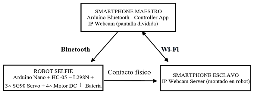
Figure 2.
Design of the Selfie Robot prototype showing the 4WD chassis, three-segment articulated arm, and slave smartphone holder.
Figure 2.
Design of the Selfie Robot prototype showing the 4WD chassis, three-segment articulated arm, and slave smartphone holder.
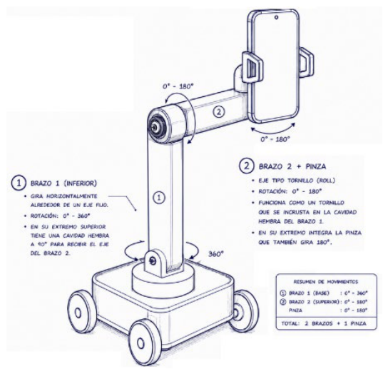
Figure 3.
Functional prototype of the constructed Selfie Robot featuring the 4WD platform, three SG90 servo arm, and integrated electronics (Arduino Nano, HC-05, L298N, Li-Ion battery).
Figure 3.
Functional prototype of the constructed Selfie Robot featuring the 4WD platform, three SG90 servo arm, and integrated electronics (Arduino Nano, HC-05, L298N, Li-Ion battery).
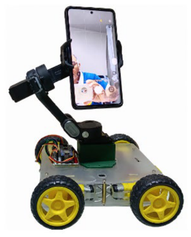
Figure 4.
Split-screen interface of the master smartphone during system operation.
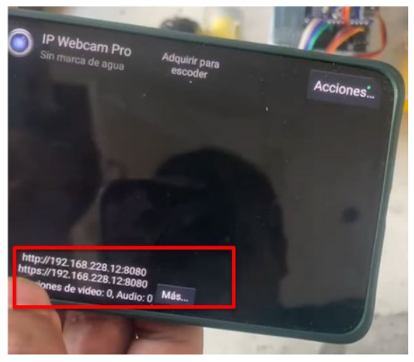
Figure 6.
Arduino Bluetooth Controller application interface during Selfie Robot operation.
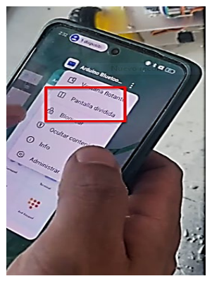

Table 1.
Hardware components and technical specifications of the Selfie Robot prototype.
| Component | Model / Value | Key specification |
|---|---|---|
| Microcontroller | Arduino Nano | ATmega328P, 16 MHz, 32 KB Flash, 2 KB RAM, 14 digital I/O pins |
| Motor driver | L298N H-Bridge | 2 A/channel, 5–46 V supply, TTL-compatible logic |
| DC motors (×4) | Generic TT motor | 3–6 V, 150 rpm @ 5 V, 200 mA no-load |
| Azimuth base servo | SG90 / MG90S | 180° rotation, 4.8–6 V, 1.8 kg·cm torque |
| Arm elevation servo | SG90 / MG90S | 180° rotation, 4.8–6 V, 1.8 kg·cm torque |
| Camera tilt servo | SG90 / MG90S | 180° rotation, 4.8–6 V, 1.8 kg·cm torque |
| Bluetooth module | HC-05 | Class 2, 2.4 GHz, up to 10 m indoors, SPP profile, 9600 bps |
| Battery | Li-Ion pack | 7.4 V / 2000 mAh, integrated TP4056 charge board |
| Chassis | 4WD Robot Car Kit | ABS plastic, ~200×150×60 mm, differential steering |
| Slave smartphone | Android ≥ 6.0 | Rear camera ≥ 8 MP; Wi-Fi 2.4/5 GHz; IP Webcam app |
| Master smartphone | Android ≥ 6.0 | Bluetooth 4.0; Arduino Bluetooth Controller + IP Webcam viewer |
Table 2.
Description of the five controllable degrees of freedom (DOF) of the Selfie Robot system.
| DOF | Type | Control axis | Range | Command bytes |
|---|---|---|---|---|
| 1 | Translational | Forward / Backward | Unlimited (chassis) | F / B |
| 2 | Rotational | Differential turn L/R | Unlimited (chassis) | L / R |
| 3 | Angular (servo) | Azimuth base | 0°–180° | X / Y |
| 4 | Angular (servo) | Arm elevation | 0°–180° | W / U |
| 5 | Angular (servo) | Camera tilt | 0°–180° | K / J |
Table 3.
Arduino Nano connection map.
| Digital Pins | Power Supply | Peripheral Modules |
| Pin 2 → HC-05 TXD Pin 3 → HC-05 RXD Pin 4 → Servo tilt (φ3) Pin 5 → L298N IN4 (PWM) Pin 6 → L298N IN3 (PWM) Pin 7 → Servo arm (φ2) Pin 8 → Servo base (φ1) Pin 9 → L298N IN2 (PWM) Pin 10 → L298N IN1 (PWM) | Battery 7.4 V → L298N Vs L298N Vss 5 V → Arduino Vin L298N Vss 5 V → Servos (×3) Arduino 3.3 V → HC-05 VCC Decoupling: 100 nF ceramic + 1000 µF electrolytic at L298N input | HC-05: UART 9600 bps, BT SPP, up to 10 m L298N: 2 channels, 2 A/ch, 4 DC motors in pairs SG90 servos: PWM 50 Hz, 1–2 ms, 0°–180° TT motors: 4 units, front/rear pairs per channel |
Table 4.
Bluetooth ASCII command vocabulary and actuator action in the Selfie Robot.
| Byte | Function | Actuator action |
|---|---|---|
| F | Forward | IN1=0, IN2=255, IN3=0, IN4=255 — wheels forward; resets watchdog |
| B | Reverse | IN1=255, IN2=0, IN3=255, IN4=0 — wheels reverse; resets watchdog |
| R | Turn right | IN1=255, IN2=0, IN3=0, IN4=255 — differential right turn |
| L | Turn left | IN1=0, IN2=255, IN3=255, IN4=0 — differential left turn |
| S | Stop | Electric brake (all HIGH); resets watchdog |
| W/w | Arm up | Arm servo (x2) += 5°; upper limit 180° |
| U/u | Arm down | Arm servo (x2) −= 5°; lower limit 0° |
| X/x | Base clockwise | Base servo (x1) += 5°; upper limit 180° |
| Y/y | Base counter-clockwise | Base servo (x1) −= 5°; lower limit 0° |
| K | Tilt + | Tilt servo (x3) += 5°; upper limit 180° |
| J | Tilt − | Tilt servo (x3) −= 5°; lower limit 0° |
Table 5.
Sequential seven-step operation protocol of the Selfie Robot.
| Step | Action |
|---|---|
| 1 | Connect the slave smartphone to the local Wi-Fi network. Open IP Webcam, select the rear camera, and press ‘Start server’. |
| 2 | Note the IP address displayed by IP Webcam (e.g., 192.168.x.x:8080) and verify the video stream. |
| 3 | On the master smartphone, connect to the same Wi-Fi network. Open the browser and enter the slave IP address to verify video server connectivity. |
| 4 | Open Arduino Bluetooth Controller and pair the HC-05 module (code: 1234 or 0000). Verify successful connection. |
| 5 | Activate split screen: IP Webcam (rear camera viewer) on one half and Arduino Bluetooth Controller on the other. |
| 6 | Position the robot at the desired distance (up to 10 m) using translational controls (F/B/R/L). Adjust the arm (W/U, X/Y, K/J) until the scene is perfectly framed. |
| 7 | When the composition is satisfactory (verified in the master viewer), execute the photographic capture from the master smartphone via the IP Webcam interface. |
Table 6.
Bluetooth communication range test results.
| Distance (m) | Commands sent | Received | Success (%) | Observed latency |
|---|---|---|---|---|
| 1 | 50 | 50 | 100.0 | Immediate |
| 3 | 50 | 50 | 100.0 | Immediate |
| 5 | 50 | 50 | 100.0 | Immediate |
| 7 | 50 | 50 | 100.0 | Minimal |
| 10 | 50 | 50 | 100.0 | Perceptible (slightly perceptible delay) |
Table 7.
Performance comparison between the proposed Selfie Robot and reference systems.
| Metric | Selfie stick / tripod | UAV gimbal — Liu et al. [12] | Smartphone robot — Ikpeze et al. [11] | Proposed Selfie Robot |
|---|---|---|---|---|
| Max. operational distance | ~0.8–1.5 m | UAV flight range | Unlimited (Wi-Fi) | 10 m (BT) |
| Degrees of freedom | 1 (manual) | 3 (stabilization) | 2 DOF | 5 DOF |
| Remote motion control | No | Autonomous (no human) | Yes (Wi-Fi) | Yes (Bluetooth) |
| Real-time video streaming | No | Onboard only | Yes | Yes (IP Webcam) |
| Camera used | Front | Rear | Rear | Rear |
| Full remote photographic control | No | No | No | Yes (zoom, brightness, burst) |
| Automatic safety stop | N/A | N/A | Not documented | Yes (100 ms watchdog) |
| Approximate cost | USD 5–15 | USD 150–300 | USD 60–90 | < USD 35 |
Disclaimer/Publisher’s Note: The statements, opinions and data contained in all publications are solely those of the individual author(s) and contributor(s) and not of MDPI and/or the editor(s). MDPI and/or the editor(s) disclaim responsibility for any injury to people or property resulting from any ideas, methods, instructions or products referred to in the content. |
© 2026 by the authors. Licensee MDPI, Basel, Switzerland. This article is an open access article distributed under the terms and conditions of the Creative Commons Attribution (CC BY) license (http://creativecommons.org/licenses/by/4.0/).
Copyright: This open access article is published under a Creative Commons CC BY 4.0 license, which permit the free download, distribution, and reuse, provided that the author and preprint are cited in any reuse.