

Submitted:
22 May 2026
Posted:
22 May 2026
You are already at the latest version
Abstract
Coaxial magnetic gears (CMGs) have emerged as a promising alternative to conventional mechanical gear systems due to their contactless torque transmission, low maintenance requirements, and high reliability, particularly in high-speed applications. However, under high-speed operating conditions, conductivity-induced eddy current losses especially in permanent magnet regions become dominant, significantly limiting the thermal performance of the system. In this study, two CMG models with identical torque capacity but different core materials are comparatively investigated. Model 1 employs conventional M400-50A electrical steel, whereas Model 2 utilizes cobalt-based Hiperco 50A, which offers higher saturation flux density and superior thermal conductivity. Detailed finite element models are developed, followed by coupled electromagnetic and thermal analyses over a wide operating speed range of 1000–12000 rpm. The results demonstrate that the use of Hiperco 50A reduces core losses by up to 71% at high speeds, leading to a more uniform temperature distribution, particularly in outer rotor components. In addition, approximately 7.3% volumetric compactness is achieved due to its higher saturation capability. Nevertheless, eddy current losses are found to dominate at high speeds, causing magnet temperatures in the inner rotor to exceed the allowable limits of NdFeB materials. This indicates that material improvement alone is insufficient without effective thermal management strategies. The findings clearly show that material selection in high-speed CMG design directly governs not only electromagnetic performance but also thermal operating limits. Therefore, coordinated consideration of material selection and thermal management is essential to ensure safe and reliable operation.
Keywords:
magnetic gear
; high-speed operation
; thermal analysis
; core loss analysis
; compact gear design
; transient magnetic simulation
1. Introduction
Magnetic gears have emerged in recent years as an attractive alternative for high-efficiency applications due to their contactless torque transmission, silent operation, low maintenance requirements, and wear-free mechanical structure [1,2]. In electric motor design, higher volumetric and gravimetric torque density is increasingly targeted; combining low-torque, high-speed motors with high-torque reduction gears offers significant advantages in terms of size and weight in drive systems [3,4]. However, efficiency limitations of low-speed motors necessitate the use of gear solutions that allow operation within the efficient speed range, while mechanical gears operating at high speeds suffer from reduced efficiency and reliability issues [5,6,7,8]. Magnetic gears overcome these drawbacks by minimizing friction-related losses inherent to conventional gear systems and alleviating mechanical constraints. They are particularly favored in applications where compactness, light weight, and high reliability are critical, such as aerospace, space systems, and electric actuators [9,10]. However, under high-speed operating conditions, the electromagnetic and thermal performance of magnetic gears poses significant engineering challenges. Increasing frequency raises core losses, which disrupt the system’s thermal balance and may cause permanent magnets to approach their maximum operating temperatures [11,12,13]. At temperatures near the Curie point, this can lead to demagnetization, adversely affecting torque production and electromagnetic reliability [14,15]. Magnets located in the inner rotor are thermally the most sensitive components due to their limited exposure to convective cooling, and temperature rise in this region is a key factor in magnet stability [16]. In magnetic gears, heat transfer is primarily achieved through the thermal conductivity of the core material and convective cooling, while laminated structures with their low thermal conductivity can trigger significant temperature rises during high-speed operation [17].
Recent studies demonstrate that advancements in electromagnetic and thermal analysis techniques have strengthened design optimization capabilities. Advanced iron-loss models, which account for rotating magnetic field components, allow for accurate identification of loss sources and enable evaluation of the effects of design improvements such as permanent magnet segmentation [19], while analytical formulations have also been proposed for superconductive MG systems [20]. Alongside material-based optimization, topological improvements play a critical role in overall system performance [22,23]. Material-comparison-focused studies have shown that soft magnetic composites (SMCs) and laminated steel stacks can exhibit similar efficiency trends, while materials with high saturation flux density offer the potential to transmit the same torque in a smaller volume [24,25,26,27]. However, compact designs can reduce cooling surface area, making thermal management more challenging [25]. In this regard, both the magnetic and thermal properties of the material must be assessed in a balanced manner. Existing literature on magnetic gears addresses topics such as the design of different topologies (coaxial, radial, axial, flux-switching, etc.), torque density optimization, and electromagnetic performance analysis [9,10,22,23,28,29]. Some studies focus on torque production and efficiency [24,26], others on low-cost design [25], or on loss prediction and thermal modeling for high-speed applications [11,12,13,30]. However, the majority of these works do not comprehensively examine the effects of core material physical properties such as thermal conductivity and saturation on the performance of high-speed CMG systems. Furthermore, the compactness and heat dissipation advantages offered by high-saturation alloys (e.g., Hiperco 50A) have mostly been discussed in the context of other types of electrical machines, and have not been the subject of detailed multiphysics analyses specifically for CMGs [31,32,33]. This study is among the few that comparatively investigate the effects of different core materials (M400-50A and Hiperco 50A) on compactness, electromagnetic performance, and thermal management in high-speed CMG applications under identical torque capacity. Using developed multiphysics FE models, electromagnetic and thermal behavior were integrated and analyzed at different frequencies, revealing material-based performance limits. Accordingly, a comparative overview of selected magnetic gear–focused studies from the literature is presented in Table 1, which clearly highlights the existing research gap. This gap is particularly critical in high-speed CMG applications, as improper material selection in high-speed CMG systems can lead to excessive losses and severe thermal accumulation, resulting in irreversible demagnetization of permanent magnets and degradation of torque transmission capability. Therefore, a comprehensive understanding of the coupled electromagnetic–thermal effects of core materials is essential for ensuring reliable operation, defining safe operating limits, and enabling the practical deployment of compact magnetic gear systems in high-speed applications.
In CMG systems, the increasing demand for high-speed power transmission has heightened the importance of advanced core materials and optimized thermal management strategies. In this study, two CMG models with identical torque capacity but different core materials are comparatively evaluated. Model 1 is designed using conventional M400-50A electrical steel, whereas Model 2 employs cobalt-based Hiperco 50A, which offers higher saturation flux density and superior thermal conductivity, enabling a more compact design. Detailed finite element models were developed, followed by electromagnetic and thermal analyses over a wide range of operating speeds. The integrated analysis results reveal the material-dependent performance limits under high-speed operating conditions. The findings provide valuable guidance for material-oriented design strategies and highlight potential development pathways for future high-performance CMG applications. The remainder of this paper is organized as follows. Section 2 presents the design methodology of the proposed CMG models, including operating principles, material selection, and finite element modeling details. Section 3 provides the electromagnetic analysis, focusing on flux distribution, torque characteristics, and loss behavior under different operating conditions. Section 4 presents the thermal evaluation based on the loss data obtained from electromagnetic simulations, highlighting temperature distribution and thermal limitations. Section 5 discusses the integrated electromagnetic and thermal performance of the proposed models, including multi-criteria comparisons and application-oriented interpretations. Finally, Section 6 concludes the study and outlines potential directions for future work.
2. Methodology: Compact Magnetic Gear Models and Material-Driven Design Strategy
2.1. Operating Principles and Design Specifications of the Proposed Magnetic Gear
As illustrated in Figure 1, the schematic cross-sectional view of the proposed CMG assembly highlights its four primary sections: the inner rotor, the modulator, the outer rotor, and the gear housing. The inner rotor comprises the high-speed shaft, the inner rotor yoke, the inner rotor permanent magnets (PMs), and a locknut for axial fixation. The modulator consists of the low-speed shaft, two non-magnetic carrier rings, ten ferromagnetic segments, a bearing housing, and a retaining ring. The ferromagnetic material of the carrier is solid, and no lamination has been used. The outer rotor includes the outer rotor yoke and outer rotor PMs, while the gear housing is formed by the front and rear covers.
During operation, torque transmission is achieved through the interaction of magnetic fields generated by the PMs on the inner and outer rotors, mediated by the ferromagnetic segments of the modulator. The modulator alters the harmonic components of the magnetic field produced by the rotor PMs, enabling contactless torque transfer between the high-speed inner rotor (input) and the low-speed outer rotor (output), according to the gear ratio. Based on this pole pair combination, a gear ratio of approximately 3.33:1 is obtained. The detailed derivation of the gear ratio and the design methodology of the proposed configuration are presented in [24]. This gear ratio is selected to represent a typical speed reduction requirement in high-speed applications, where the high-speed inner rotor is converted into a lower-speed, higher-torque output, which is particularly relevant for aerospace and electric drive systems.
The magnetic field configuration is determined by the number of PM pole pairs on each rotor and the number of ferromagnetic segments in the modulator. In the presented configuration, the inner rotor contains three pole pairs, the outer rotor contains seven pole pairs, and the modulator holds ten ferromagnetic segments. The electromagnetic performance of the CMG is strongly influenced by the magnetic and thermal properties of the yoke and ferromagnetic segment materials, including permeability, saturation flux density, electrical resistivity, and thermal conductivity. Two material configurations are compared in this study: (i) M400-50A electrical steel, representing a conventional industrial choice, and (ii) Hiperco 50A, offering higher saturation flux density and improved thermal conductivity, enabling a more compact CMG design while maintaining equivalent torque transmission capacity. The configuration employing M400 50A electrical steel is denoted as Model 1, whereas the configuration based on Hiperco 50A is referred to as Model 2. The geometric parameters used in the finite element analyses are illustrated in Figure 2, with their corresponding numerical values summarized in Table 2. As shown in Figure 2, the inner radii are abbreviated as IR, while the outer radii are denoted as OR for clarity. In both models, the volumetric torque density was kept constant as a reference parameter; however, key geometrical dimensions such as the outer diameter, active volume, and carrier radius were optimized according to the magnetic characteristics of the selected material. The fundamental geometric parameters defining the proposed CMG designs are comprehensively presented in Table 2.
2.2. Material Specification and Design Rationale
The selection of M400-50A and Hiperco 50A as core materials, guided by electromagnetic performance objectives, was decisive in shaping the overall design. M400-50A, a widely used electrical steel, is favored in conventional applications due to its low cost, broad availability, and compatibility with established manufacturing processes. However, its relatively low saturation flux density (Bₛₐₜ) and limited thermal conductivity may impose constraints in compact designs where high torque density is required. By contrast, Hiperco 50A, a cobalt-based magnetic alloy, offers superior magnetic properties such as a high saturation flux density (~2.35 T), low relative magnetic permeability, and high thermal conductivity [36]. The fundamental electromagnetic and thermal properties of these two materials including magnetic permeability, saturation flux density, electrical resistivity, and thermal conductivity are presented in Table 3.
Thanks to its superior characteristics, Hiperco 50A enables the same torque capacity to be achieved with a smaller volume, thereby supporting a more compact system design. Nevertheless, its high cost and certain challenges related to machinability restrict its use to specific critical applications. At high operating speeds, however, Hiperco 50A demonstrates distinct advantages in terms of loss and thermal performance, attributable to its higher saturation level and reduced core losses. Figure 3 illustrates the B–H and magnetic permeability characteristics of the materials, while Figure 4 presents the frequency-dependent comparison of core losses for M400-50A and Hiperco 50A. These curves were obtained using the material data specified in Ref. [36].
In the designed magnetic gear system, permanent magnets represent the most temperature-sensitive components. Therefore, the temperature-dependent B–H characteristics of the employed NdFeB (N35UH) magnet are presented in Figure 5, illustrating the degradation of magnetic properties under elevated temperature conditions.
2.3. Finite Element Modeling Setup
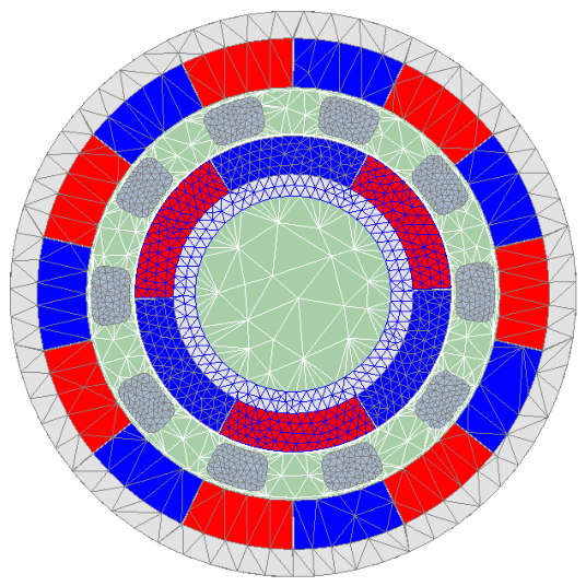
The electromagnetic analyses were performed using 2D transient finite element simulations in Ansys Maxwell with a 1 ms time step and a total simulation duration of 50 ms. A 2D model was selected due to the rotational symmetry of the coaxial magnetic gear and the dominance of radial flux. An adaptive mesh was employed, yielding approximately 5.1×10⁵ triangular elements overall. Regions with steep flux gradients, particularly the air gap and permanent magnet edges, were locally refined to a minimum element edge length of ~35 µm, while low-gradient regions used a coarser mesh. A mesh convergence check showed that increasing the element count by ~25% altered the average torque by <0.5%, confirming mesh independence. To model the external field without artificial confinement, a circular outer region sufficiently larger than the active geometry was defined, and a Periodic Boundary Condition (PBC) was applied on this boundary to enforce flux periodicity. Excitations were prescribed via current densities on the inner and intermediate rotor magnets, while the rotor and ferromagnetic poles were modeled with floating boundaries.
Figure 6.
Finite element mesh structure employed in the transient electromagnetic analysis of the proposed CMG model.
Figure 6.
Finite element mesh structure employed in the transient electromagnetic analysis of the proposed CMG model.
3. Electromagnetic Analysis
The electromagnetic performance of the magnetic gear models was performed through transient magnetic analyses conducted in Ansys Maxwell. The magnetic flux density distributions obtained for both models were comparatively analyzed in terms of saturation behavior and flux guiding capability. Figure 7 presents the magnetic flux density distributions under different material and speed conditions, where the behaviors of M400-50A and Hiperco 50A are compared at 1000 rpm and 12000 rpm, corresponding to the mechanical rotational speed of the inner rotor.
As illustrated in Figure 7, under low-speed operation (1000 rpm), the M400-50A and Hiperco 50A models exhibit similar flux density distributions. At higher speeds (12000 rpm), however, the M400-50A model shows localized regions approaching magnetic saturation, particularly around the ferromagnetic segments of the inner rotor and in areas adjacent to the air gap. This behavior is attributed to the relatively lower saturation flux density (Bₛₐₜ) of M400-50A, which leads to flux crowding in certain regions of the magnetic circuit at higher rotational speeds under the same torque transmission conditions.
In contrast, the Hiperco 50A model, owing to its higher Bₛₐₜ value and superior magnetic permeability, achieves the same torque transfer with a more uniform flux distribution, thereby significantly reducing magnetic loading in critical regions. This effect manifests as lower local flux peaks in the modulator teeth and along the magnet edges at high frequency, contributing to a reduction in core losses and mitigating localized heating tendencies. Consequently, the high saturation capability and superior magnetic properties of Hiperco 50A provide a direct advantage in compact CMG designs, both in terms of electromagnetic efficiency and thermal stability. In addition, the torque generation capability and torque stability of the magnetic gears were evaluated through time-dependent analyses. For both models, the torque–time waveforms obtained at low and high speed ranges are presented in Figure 7, while the corresponding average torque and torque ripple values are summarized in Table 4.
As shown in Figure 8, the average torque values for M400-50A are 12.65 N·m (input) and 41.76 N·m (output) at the lowest speed, and 14.15 N·m (input) and 43.14 N·m (output) at the highest speed. For the Hiperco material, the corresponding values were 12.43 Nm and 41.81 Nm at the lowest speed, and 13.02 Nm and 41.85 Nm at the highest speed. While both materials provided a T_out/T_in ratio close to the gear ratio at low speed, at high speed this ratio decreased by approximately 7.6% for M400-50A, whereas the reduction for Hiperco 50 remained limited to about 4.4%. Owing to its higher saturation flux density, Hiperco 50 is able to maintain stronger magnetic coupling at elevated speeds, resulting in a smaller reduction in torque transmission efficiency compared to M400-50A. With increasing speed, the input torque rises while the output torque remains almost unchanged, indicating the stronger influence of eddy current and hysteresis losses at higher speeds in M400-50A. The torque ripple ratios and average torque values were calculated numerically from Figure 8, and the results are summarized in Table 4.
As presented in Table 4, torque ripple ratios were evaluated for the output torque under both low- and high-speed operating conditions. At 1000 rpm, the output torque ripples for M400-50A and Hiperco 50A were found to be relatively low, at 4.45% and 4.41%, respectively. In the high-speed range, however, the torque ripple increased to 7.09% with M400-50A, whereas it decreased to 4.38% when Hiperco 50A was employed. These findings suggest that at higher rotational speeds, Hiperco 50A leads to a noticeable reduction in torque ripple, which may improve torque transmission characteristics. To complement the torque ripple evaluation, the speed-dependent loss behavior of the magnetic gears was analyzed, as losses play a critical role in determining efficiency and thermal performance. The variation of losses over the entire operating speed range is presented, while representative loss distributions for M400-50A and Hiperco 50A at 1000 rpm and 12000 rpm are shown in Figure 9.
As illustrated in Figure 9, the loss behavior of the magnetic gears exhibits a clear dependence on both the material type and the operating speed. At low-speed operation (1000 rpm), the total losses of M400-50A and Hiperco 50A remain at comparable levels, with averages of 6.50 W and 6.35 W, respectively. In this regime, solid (eddy-current) losses dominate the overall profile, accounting for more than 80% of the total dissipation, while the difference in core losses between the two materials remains minor. In contrast, at high-speed operation (12000 rpm), the divergence becomes more pronounced. M400-50A records a total loss of approximately 1.18 kW (87 W core, 1.09 kW solid), whereas Hiperco 50A achieves a lower total loss of approximately 1.10 kW, corresponding to a ~7% reduction in total losses, mainly attributed to significantly reduced core losses (25 W), which are decreased by nearly 71% compared to M400-50A.While the loss distributions at specific operating points provide valuable insight, a more comprehensive understanding of the system behavior requires evaluating the variation of losses and efficiency over the entire operating speed range. Therefore, the speed-dependent characteristics of total losses and efficiency are presented in Figure 10.
As shown in Figure 10, the total losses increase significantly with increasing rotational speed for both materials, primarily due to the rapid growth of eddy-current (solid) losses. Although both models exhibit a similar trend, the Hiperco 50A configuration consistently demonstrates lower total losses, particularly at higher speeds. The efficiency curves reveal that both models maintain high efficiency at low speeds; however, a noticeable decline occurs as the speed increases. This reduction is directly associated with the increasing dominance of loss mechanisms at elevated rotational speeds. Compared to M400-50A, the Hiperco 50A model exhibits slightly higher efficiency, especially in the high-speed region, owing to its reduced core losses. These findings provide a clear explanation for the thermal behavior observed in the subsequent analysis, where the rapid increase in losses at higher speeds leads to significant temperature rise in critical components of the magnetic gear system.
4. Thermal Evaluation
To evaluate the thermal behavior of magnetic gears under different speed conditions, thermal analyses were performed in Ansys Fluent for two core materials (M400-50A and Hiperco 50A) using the loss data obtained from electromagnetic simulations. The simulations were carried out using a steady-state solution approach in order to investigate the thermal equilibrium of the system. In the thermal models, the core losses originating from the conductors were defined as heat sources, while natural convection cooling was applied at the external surfaces to represent air cooling. Instead of adiabatic boundary conditions, fixed ambient boundaries were introduced on the outer surfaces to allow heat exchange with the surroundings. The mesh structure was refined particularly in regions with expected high heat flux density, thereby improving solution accuracy in capturing temperature gradients.
The analyses were conducted for both models operating at a 3.33:1 gear ratio with a power transfer capacity of 1.3 kW, within the operating speed range of 1000 rpm to 12000 rpm. Six critical components were considered: the inner yoke, inner magnets, modulator, outer magnets, outer yoke, and housing. The temperature variations of these components for both materials are presented in Figure 11.
Figure 11 presents the comparative thermal response of six key components housing, inner PM, inner yoke, modulator, outer PM, and outer yoke under different operating speed conditions for the two core materials, M400-50A and Hiperco 50A. At low-speed operation (1000 rpm), the temperature values of all components are very close to each other. For example, the housing exhibits 58.41 °C for M400-50A and 58.59 °C for Hiperco 50A, the inner PM 64.30 °C and 66.85 °C, the inner yoke 64.67 °C and 66.90 °C, the modulator 65.43 °C and 65.75 °C, the outer PM 57.68 °C and 58.86 °C, and the outer yoke 54.85 °C and 58.63 °C. In this regime, the differences induced by material selection remain limited. At high-speed operation (12000 rpm), however, the absolute temperatures rise sharply, while Hiperco 50A shows a noticeable thermal improvement in the outer components, whereas the temperature differences in the inner regions remain limited. The component-specific values are as follows: the housing reaches 427.90 °C for M400-50A and 411.84 °C for Hiperco 50A, the inner PM 494.46 °C and 492.79 °C, the inner yoke 494.86 °C and 493.17 °C, the modulator 483.48 °C and 480.92 °C, the outer PM 431.21 °C and 415.05 °C, and the outer yoke 428.40 °C and 412.33 °C. The results indicate that the highest absolute temperatures accumulate in the inner regions (inner PM and inner yoke, approximately 493–495 °C), whereas the largest relative reductions are observed in the housing and outer yoke/PM. It should be noted that the inner PM temperatures (≈493–495 °C) significantly exceed the Curie temperature of NdFeB magnets (~310–320 °C). Such extreme temperatures surpass the allowable operating limits of NdFeB magnets and would inevitably lead to irreversible demagnetization in practical applications. Therefore, these results do not represent a physically sustainable operating condition, but rather correspond to a worst-case scenario in the absence of active cooling, highlighting the necessity of effective thermal management solutions. These thermal trends are fully consistent with the electromagnetic loss analysis presented in the previous section, where the rapid increase in eddy-current losses at higher speeds was identified as the dominant heat generation mechanism. Accordingly, the superior high-speed performance of Hiperco 50A in reducing core losses translates into a tangible thermal benefit in the peripheral components, namely the housing and the outer yoke/PM. In contrast, the relatively small differences observed in the inner regions indicate that total heating is predominantly governed by eddy current (solid) losses, which remain dominant at elevated rotational speeds.
Consequently, Hiperco 50A contributes to a more favorable thermal distribution under high-speed operation, particularly in the outer components, while the improvement remains limited in magnet-dense inner regions where heat accumulation is most critical. Due to the temperature-sensitive nature of permanent magnets, a region-based visualization approach is applied to PM components (both inner and outer magnets) to distinguish safe and critical operating conditions. This visualization is adopted to more clearly illustrate the rapid temperature rise trends in magnet regions. It should be noted, however, that the inner PM reaches critical temperature levels at lower rotational speeds, indicating that the actual safe operating region is primarily limited by the thermal constraints of the inner magnets. To provide a more meaningful evaluation of the temperature trends, the average temperature difference (ΔT) among all components was analyzed. Figure 12 illustrates the trend of the average temperature difference (ΔT) for the Outer PM, Inner PM, and Modulator components, comparing M400-50A and Hiperco 50A. This difference is expressed by Equation (1).
ΔT=T M400-50A −T Hiperco 50 A (1)
Figure 13 presents the variation of the temperature difference (ΔT) between M400-50A and Hiperco 50A materials with rotational speed for the outer magnet, identified as the most critical thermal component of the system. According to the analysis results, the ΔT value reaches its maximum level at 12000 rpm with 16.16 °C. This finding indicates that the outer magnet region is one of the thermally critical components in terms of temperature difference (ΔT), although the highest absolute temperature levels are observed in the inner regions. The nonlinear trend of the curve indicates that the temperature rise is not solely dependent on frequency or rotational speed but is also associated with the approach of the M400-50A material to its magnetic saturation point. The heat accumulation in this region is particularly concerning, as it has the potential to exceed the maximum allowable temperature limits of the permanent magnets, thereby increasing the risk of demagnetization. The ΔT trend further shows a tendency to approach critical thermal thresholds at high speeds, emphasizing the necessity of implementing effective thermal management strategies (e.g., advanced cooling solutions, material optimization) in high-speed applications. To enable a clearer visualization of the findings obtained from the ΔT analysis, Figure 14 presents the component-wise temperature distribution for both materials (M400-50A and Hiperco 50A).
When Figure 14 is examined, it is observed that even at low-speed operation (1000 rpm), the M400-50A material reaches higher temperature values in all critical regions compared to Hiperco 50A. Although the temperature difference in the inner yoke, modulator, and outer magnet regions remains at the level of a few degrees, this indicates that thermal accumulation may occur more rapidly under steady-state conditions. To observe the temperature distributions under high-speed conditions, Figure 15 presents a comparative visualization of the temperature contours of critical components for both materials under 12000 rpm) operation.
When Figure 15 is examined, it is evident that the temperature levels in all components are significantly higher for M400-50A compared to Hiperco 50A. In particular, the temperature of M400-50A reaches approximately 493 °C in the inner yoke and inner magnet regions, while Hiperco 50A remains around 489 °C in the same areas. A similar trend is observed in the modulator region, whereas in the outer magnet region Hiperco 50A provides an advantage of about 6 °C. As shown in the previous results, the predicted steady-state temperatures in the inner permanent magnets reach unrealistically high levels, exceeding the Curie temperature of NdFeB (~310–320 °C), particularly at high rotational speeds. These extreme temperature levels primarily result from the inclusion of eddy-current and permanent magnet losses in the thermal model, which become increasingly dominant as rotational speeds increase. To better isolate the material effect and obtain a clearer comparison of their intrinsic thermal behavior, additional analyses were performed with and without considering eddy current losses. To clarify how this inclusion or exclusion influences the ΔT analysis, Figure 16 and Figure 17 present a comparative visualization of the temperature fields at low-speed operation (1000 rpm) for both core materials.
As can be seen from both figures, the elimination of eddy current losses leads to a noticeable reduction in component temperatures and a more uniform temperature distribution. This clearly confirms that eddy-current losses constitute the dominant heat source in the thermal behavior of the magnetic gear under high-speed operation. The M400-50A material, due to its lower thermal conductivity, exhibits more pronounced local temperature rises, whereas the Hiperco 50A material, with its higher thermal conductivity and saturation flux density, demonstrates both lower peak temperature values and a more balanced temperature profile. This clearly indicates that thermal conductivity is a critical design parameter in material selection, particularly in applications where eddy current losses dominate under high-speed operation.
The literature also points out that under high-speed and high-flux-density conditions, Hiperco 50A cores, with their higher saturation flux density (Bs) and suitable lamination thickness, can reduce local saturation and thereby provide better thermal performance margins [6,30,32,33,38]. In magnetic gears, it has also been demonstrated that core losses vary strongly with material properties and lamination thickness, and that upgrading the core material can reduce both losses and peak temperatures [11,16,19,25,39].
In light of all these findings, the maximum temperature values and hot spot locations were comparatively evaluated. For the M400-50A model, the maximum temperature reached 494.9 °C, with the hot spot occurring in the inner permanent magnet (PM). Similarly, in the Hiperco 50A model, the maximum temperature reached 493.2 °C, and the hot spot was also located in the inner PM.
5. Discussion
As a result of the analyses conducted, the electromagnetic and thermal performances of both magnetic gear models were evaluated in an integrated manner. In this study, the radar chart shown in Figure 18 was prepared for the high-speed condition, where the material differences are most pronounced. In this challenging operating regime, where eddy current losses dominate, the direct comparison of electromagnetic and thermal performances was enabled. This visualization technique is widely recognized in the literature as an effective method that supports decision-making processes, particularly in the simultaneous analysis of electromagnetic and thermal performance criteria [37]. This approach allows simultaneous evaluation of multiple performance criteria, facilitating a holistic comparison between material options. In addition to electromagnetic and thermal considerations, the structural integrity of magnetic gears has also been highlighted as a key limitation in the literature. Tallerico et al. [40] pointed out that stress accumulation, mechanical fatigue, and structural durability issues can restrict the applicability of magnetic gears in high-torque and aerospace environments. Similarly, Modaresahmadi et al. [41] demonstrated through structural modeling and experimental validation that laminated stacks require careful assessment of their mechanical stability under electromagnetic forces. These studies underline that future multiphysics evaluations of CMG systems should integrate not only electromagnetic and thermal domains but also detailed structural analysis to ensure overall system reliability. The normalized performance metrics presented in Figure 16 are based on average torque, torque ripple, maximum temperature, core loss, manufacturing cost, and compactness. Electromagnetic and thermal parameters were obtained from numerical analyses, while cost estimations were calculated by multiplying the unit price of the material with the net active mass. The manufacturability assessment followed the methodology outlined in our study [37], taking into account material machinability, applicable production techniques, and production volume. Compactness was defined in terms of achieving lower outer diameter and active volume for the same torque capacity.
Figure 18 illustrates the normalized electromagnetic and thermal performance of the two magnetic gear models under low-speed (1000 rpm) and high-speed (12000 rpm) operating conditions. At 1000 rpm, both materials exhibit a similar thermal response, while Hiperco 50A offers a limited advantage in terms of compactness.
However, the high cost and lower manufacturability of cobalt-based alloys emerge as significant drawbacks in this speed range. At 12000 rpm, the differences become more pronounced. Hiperco 50A, owing to its high saturation flux density and its ability to employ thinner laminations, demonstrates reduced core losses and improved thermal tolerance. In contrast, the M400-50A model shows considerably higher thermal stress under these conditions, limiting its applicability in high-speed operations.The thermal results further indicate that, under such high-speed operation, the predicted temperatures in the inner regions (inner PM and inner yoke) rise well above the Curie temperature of NdFeB magnets (~310–320 °C). In practice, such temperatures would cause irreversible demagnetization, making forced cooling indispensable for reliable operation. This finding highlights that thermal limitations, rather than electromagnetic performance alone, become the primary design constraint under high-speed operating conditions.
This outcome highlights that the presented thermal analysis represents a worst-case scenario without active cooling. Hence, efficient thermal management strategies such as liquid cooling, advanced heat sinks, or optimized ventilation are essential to maintain permanent magnet temperatures within safe limits and ensure the long-term stability of magnetic gear systems.
Moreover, in CMG structures, the solid loss component was identified as the dominant loss type at high speeds. In light of these findings, Hiperco 50A appears to be more suitable for aerospace applications, where thermal constraints induced by high speeds are critical, as well as for automotive systems that require compactness. On the other hand, due to its lower cost and ease of manufacturability, M400-50A can be preferred in industrial power transmission systems operating in the medium-speed range, where volume constraints are not critical and cost-effectiveness is a priority.
From a design-oriented perspective, the combined electromagnetic and thermal results enable the definition of practical material selection guidelines for CMG systems. At low-speed operation (up to approximately 4000–6000 rpm), both M400-50A and Hiperco 50A exhibit comparable loss levels and temperature distributions, indicating that conventional electrical steel remains a viable and cost-effective solution in this range. However, as the rotational speed increases beyond approximately 6000–8000 rpm, the divergence in loss behavior becomes more pronounced, primarily due to the rapid increase in eddy-current losses. In this regime, Hiperco 50A provides a clear advantage through reduced core losses and improved thermal distribution, particularly in outer components.
At high-speed operation (above ~10000 rpm), the thermal response becomes dominated by excessive loss accumulation, leading to critical temperature levels in the inner permanent magnet regions. The predicted temperatures exceeding ~490°C clearly indicate that such operating conditions are not physically sustainable for NdFeB magnets without advanced cooling. Therefore, this speed range represents a thermal limit rather than a practical operating region.
Accordingly, for high-speed CMG applications (>8000 rpm), Hiperco 50A is recommended due to its superior high-speed performance, whereas M400-50A remains suitable for medium-speed industrial applications where cost and manufacturability are prioritized. However, regardless of material selection, operation near or above ~10000 rpm requires additional thermal management strategies, such as forced cooling or design modifications, to ensure safe and reliable operation.
6. Conclusions and Future Work
This study presented an integrated electromagnetic and thermal performance evaluation of two coaxial magnetic gear (CMG) models designed with different core materials. The comparison revealed that the model employing the high-saturation flux density alloy Hiperco 50A is capable of maintaining the same power transmission capacity within a reduced volume, achieving approximately 7.3% volumetric compactness compared to the conventional M400-50A electrical steel design.
The results indicate that Hiperco 50A provides an improvement in thermal performance due to its higher thermal conductivity and reduced core losses, resulting in a more uniform temperature distribution in outer components. However, this improvement is not pronounced in magnet-dense inner rotor regions, where the highest temperatures are observed. In addition, it was observed that under high-speed operation, the predicted temperatures in the inner permanent magnets exceed the allowable limits of NdFeB materials, indicating that thermal constraints constitute a fundamental limitation in CMG systems. In this regard, material improvement alone is insufficient, and effective thermal management strategies are essential for ensuring reliable operation. From an application perspective, Hiperco 50A appears more suitable for high-speed and compact systems such as aerospace and advanced automotive applications, whereas M400-50A remains a cost-effective and practical solution for medium-speed industrial applications where volume constraints are less critical.
Furthermore, this study did not consider design variables such as rotor segmentation, alternative magnet geometries, and different cooling strategies. Future work will focus on systematically investigating the influence of these additional parameters, developing optimization approaches to mitigate eddy current losses at high rotational speeds, and validating the numerical findings through experimental studies.
Author Contributions
Conceptualization, M.A and K.Y.; methodology, K.Y, M.A.; investigation, T.D. and U.A.; resources, U.A, S.A, T.D.; writing-original draft preparation, K.Y, T.D. and U. A.; writing-review and editing, M.A., S.S. and S.A.; supervision, M.A. and K.Y. All authors have read and agreed to the published version of the manuscript.
Acknowledgments
This study was supported by the Scientific Research Projects Coordination Unit of Kocaeli University (BAP) under the Emergency Infrastructure Support Projects, grant numbers FAA-2025-4667 and FBA-2026-5129.
Conflicts of Interest
The authors declare no conflict of interest.
References
- Wang, Y.; Filippini, M.; Bianchi, N.; Alotto, P. A review on magnetic gears: Topologies, computational models, and design aspects. IEEE Trans. Ind. Appl. 2019, vol. 55(no. 5), 4557–4566. [Google Scholar] [CrossRef]
- Ruiz-Ponce, G.; Arjona, M. A.; Hernandez, C.; Escarela-Perez, R. A review of magnetic gear technologies used in mechanical power transmission. Energies 2023, vol. 16(no. 4), 1721. [Google Scholar] [CrossRef]
- Tallerico, T. F.; Scheidler, J. J.; Cameron, Z. A. Electromagnetic mass and efficiency of magnetic gears for electrified aircraft. 2019 AIAA/IEEE Electric Aircraft Technologies Symposium (EATS), 2019; pp. 1–25. [Google Scholar] [CrossRef]
- Wong, H. Y.; Baninajar, H.; Dechant, B.; Bird, J. Designing a magnetic gear for an electric aircraft drivetrain. Proc. 2020 IEEE Energy Conversion Congress and Exposition (ECCE), 2020; pp. 1–6. [Google Scholar]
- Anderson, A. D.; et al. System weight comparison of electric machine topologies for electric aircraft propulsion. 2018 AIAA/IEEE Electric Aircraft Technologies Symposium (EATS), 2018; pp. 1–16. [Google Scholar] [CrossRef]
- Zhang, X.; Bowman, C. L.; O’Connell, T. C.; Haran, K. S. Large electric machines for aircraft electric propulsion. IET Electr. Power Appl. 2018, vol. 12(no. 6), 767–779. [Google Scholar] [CrossRef]
- Scheidler, J. J. Progress in magnetic gearing for aeronautics and space applications. Energy & Mobility Conference & Expo, Sept. 2023. [Google Scholar]
- Wong, H. Y.; Baninajar, H.; Dechant, B.; Southwick, P.; Bird, J. Z. Design and experimental testing of a magnetic gear for an electric aircraft drivetrain. IEEE Trans. Ind. Appl. 2023, vol. 59(no. 4), 3934–3944. [Google Scholar] [CrossRef]
- Praslicka, B.; et al. Design and analysis of a novel, low-cost, high-speed cycloidal magnetic gear for aerospace servo actuator applications. IEEE/ASME Trans. Mechatron. 2023, vol. 28(no. 6), 3352–3363. [Google Scholar] [CrossRef]
- Benarous, M.; Trezieres, M. Design of a cost-effective magnetic gearbox for an aerospace application. J. Eng. 2019, vol. 2019(no. 17), 4081–4084. [Google Scholar] [CrossRef]
- Nikolarea, N.; et al. Detailed investigation of the eddy current and core losses in coaxial magnetic gears through a two-dimensional analytical model. Math. Comput. Appl. 2024, vol. 29(no. 3), 38. [Google Scholar] [CrossRef]
- Lee, J. I.; et al. Core-loss analysis of linear magnetic gears using the analytical method. Energies 2021, vol. 14(no. 10), 2905. [Google Scholar] [CrossRef]
- Mateev, V.; Marinova, I. Loss estimation of magnetic gears. Electr. Eng. 2020, vol. 102(no. 1), 387–399. [Google Scholar] [CrossRef]
- Gardner, M. C.; Praslicka, B.; Johnson, M.; Toliyat, H. A. Optimization of coaxial magnetic gear design and magnet material grade at different temperatures and gear ratios. IEEE Trans. Energy Convers. 2021, vol. 36(no. 3), 2493–2501. [Google Scholar] [CrossRef]
- Dobzhanskyi, O. Comparative thermal and demagnetization analysis of the PM machines with neodymium and ferrite magnets. Energies 2022, vol. 15(no. 12), 4484. [Google Scholar] [CrossRef]
- Desvaux, M.; et al. Magnetic losses and thermal analysis in a magnetic gear for wind turbine. 2018 Int. Conf. Ecological Vehicles and Renewable Energies (EVER), 2018; pp. 1–7. [Google Scholar]
- Modaresahmadi, S.; Khalesi, J.; Li, K.; Bird, J. Z.; Williams, W. B. Convective heat transfer analysis of a laminated flux focusing magnetic gearbox. Therm. Sci. Eng. Prog. DOI. 2020, vol. 18, 100552. [Google Scholar] [CrossRef]
- Gerber, S.; Wang, R. Analysis of the end-effects in magnetic gears and magnetically geared machines. Proc. 2014 ICEM, 2014; pp. 560–565. [Google Scholar]
- Filippini, M.; Alotto, P.; Cirimele, V.; Repetto, M.; Ragusa, C.; Dimauro, L.; Bonisoli, E. Magnetic loss analysis in coaxial magnetic gears. Electronics 2019, vol. 8(no. 11). [Google Scholar] [CrossRef]
- Dianati, B.; Heydari, H.; Afsari, S. A. Analytical computation of air-gap magnetic field in a viable superconductive magnetic gear. IEEE Trans. Appl. Supercond. 2016, vol. 26(no. 6), 5205612. [Google Scholar] [CrossRef]
- Li, K.; et al. Electromagnetic analysis and experimental testing of a flux focusing wind turbine magnetic gearbox. IEEE Trans. Energy Convers. 2019, vol. 34(no. 3), 1512–1521. [Google Scholar] [CrossRef]
- Rasmussen, P. O.; Andersen, T. O.; Jorgensen, F. T.; Nielsen, O. Development of a high-performance magnetic gear. IEEE Trans. Ind. Appl. 2005, vol. 41(no. 3), 764–770. [Google Scholar] [CrossRef]
- Aiso, K.; Akatsu, K.; Aoyama, Y. A novel flux-switching magnetic gear for high-speed motor drive system. IEEE Trans. Ind. Electron. 2021, vol. 68(no. 6), 4727–4736. [Google Scholar] [CrossRef]
- Dindar, T.; Yilmaz, K. Reduction of core size and power losses of a soft composite magnetic gear. Simul. Model. Pract. Theory 2025, 103135. [Google Scholar] [CrossRef]
- Kowol, M.; Kołodziej, J.; Jagieła, M.; Łukaniszyn, M. Impact of modulator designs and materials on efficiency and losses in radial passive magnetic gear. IEEE Trans. Energy Convers. 2019, vol. 34(no. 1), 147–154. [Google Scholar] [CrossRef]
- Yin, X.; Pfister, P. D.; Fang, Y. A novel magnetic gear: Toward a higher torque density. IEEE Trans. Magn. 2015, vol. 51(no. 11), 1–4. [Google Scholar] [CrossRef]
- Karabulut, Y.; Meşe, E.; Ayaz, M.; Aktaş, S. Comparison study on SMC and grain-oriented laminated steel core for small-size axial flux permanent-magnet synchronous machines. Mater. Res. Express 2024, vol. 11(no. 10), 106102. [Google Scholar] [CrossRef]
- Mateev, V.; Marinova, I. Modeling of low-speed magnetic gear with viscose ferrofluid. COMPEL 2022, vol. 41(no. 5), 1956–1970. [Google Scholar] [CrossRef]
- Gardner, M. C.; Johnson, M.; Toliyat, H. A. Comparison of surface permanent magnet axial and radial flux coaxial magnetic gears. IEEE Trans. Energy Convers. 2018, vol. 33(no. 4), 2250–2259. [Google Scholar] [CrossRef]
- Dong, B.; Wang, K.; Han, B.; Zheng, S. Thermal analysis and experimental validation of a 30 kW 60,000 r/min high-speed permanent magnet motor with magnetic bearings. IEEE Access 2019, vol. 7, 92184–92192. [Google Scholar] [CrossRef]
- Mezani, S.; Atallah, K.; Howe, D. A high-performance axial-field magnetic gear. J. Appl. Phys. 2006, vol. 99(no. 8). [Google Scholar] [CrossRef]
- Di Nardo, M.; et al. High-speed synchronous reluctance machines: Materials selection and performance boundaries. IEEE Trans. Transp. Electrif. 2021, vol. 8(no. 1), 1228–1241. [Google Scholar] [CrossRef]
- Vannini, A.; et al. Materials for electric machines suited for high-temperature applications: a survey. Proc. IEEE WEMDCD, 2021; pp. 101–106. [Google Scholar]
- Sohrabzadeh, A.; Shariati, A.; Torkaman, H. Electromagnetic-thermal analysis of a reluctance magnetic gear. 2024 Int. Conf. Electr. Machines and Drives (ICEMD), 2024; pp. 1–6. [Google Scholar]
- Zarghani, A.; et al. Thermal modeling and analysis of a transverse-radial flux magnetic gear. 2023 Int. Conf. Electr. Machines and Drives (ICEMD), 2023; pp. 1–7. [Google Scholar]
- SMAG, SMAG Handbook Version 7, 2021. Available online: https://www.magweb.us/wp-content/uploads/2021/08/SMAG-Handook-Version-7.pdf (accessed on FEB. 17 2025).
- Sezen, S.; Yilmaz, K.; Aktas, S.; Ayaz, M.; Dindar, T. Solid core magnetic gear systems: A comprehensive review of topologies, core materials, and emerging applications. Appl. Sci. vol. 15(no. 15), 8560, 2025. [CrossRef]
- Karabulut, Y.; et al. Thermal analysis of small-scale axial flux permanent magnet synchronous motors for LVAD systems. IEEE Trans. Ind. Appl. 2025, vol. 61(no. 3), 3701–3710. [Google Scholar] [CrossRef]
- Kowol, M.; Kołodziej, J.; Gabor, R.; Łukaniszyn, M.; Jagieła, M. On-load characteristics of local and global forces in co-axial magnetic gear with reference to additively manufactured parts of modulator. Energies 2020, vol. 13(no. 12), 3169. [Google Scholar] [CrossRef]
- Tallerico, T.; Scheidler, J.; Cameron, Z. Magnetic gears and their structural limitations. NASA Report No. GRC-E-DAA-TN72797, 2019. [Google Scholar]
- Modaresahmadi, S.; Barnett, D.; Baninajar, H.; Bird, J. Z.; Williams, W. B. Structural modeling and validation of laminated stacks in magnetic gearing applications. Int. J. Mech. Sci. 2021, vol. 192, 106133. [Google Scholar] [CrossRef]
- Arnold Magnetic Technologies, N35UH NdFeB Magnet B–H Curves. Available online: https://alliancemagnets.com/n35uh-neodymium-magnet-bh-curve/ (accessed on 7 May 2026).
Figure 1.
3D cross-sectional view of the proposed CMG assembly.
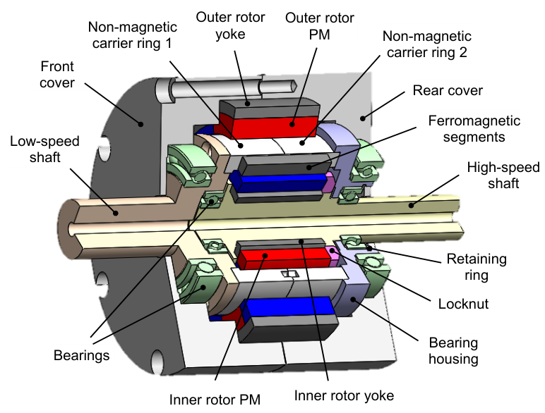
Figure 2.
Dimensional layout of the magnetic gear components in the CMG assembly.
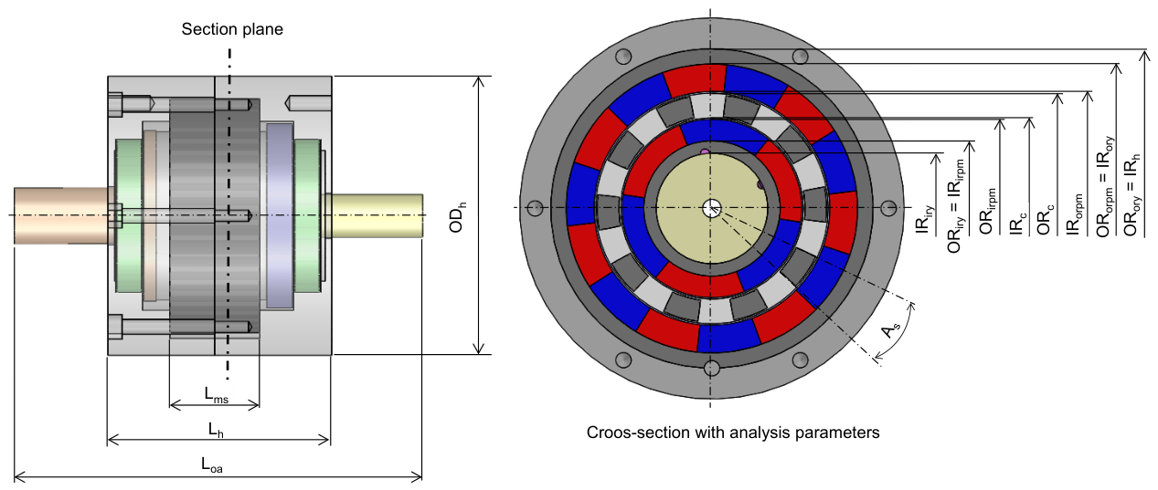
Figure 3.
B-H characteristics and magnetic permeability curves of M400–50A and Hiperco 50A [36].
Figure 3.
B-H characteristics and magnetic permeability curves of M400–50A and Hiperco 50A [36].
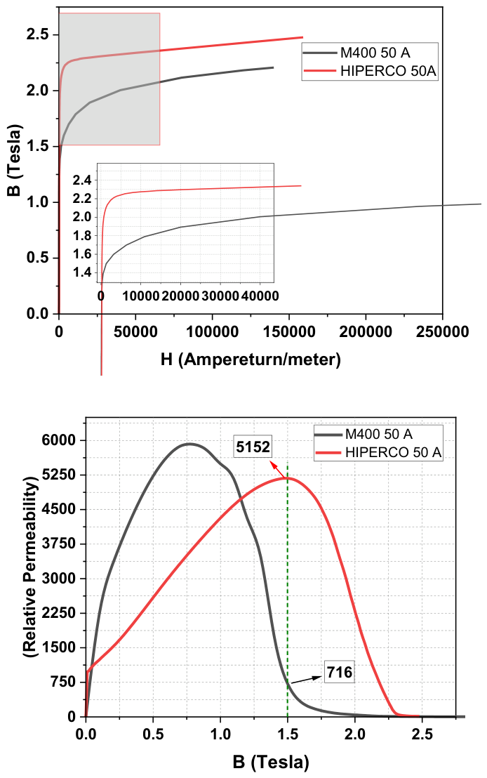
Figure 4.
Core loss comparison of M400-50A and Hiperco 50A [36].
Figure 4.
Core loss comparison of M400-50A and Hiperco 50A [36].
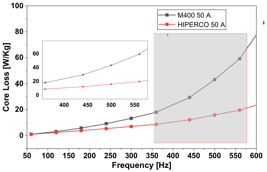
Figure 5.
Temperature-dependent demagnetization (B–H) curves of the NdFeB (N35UH) permanent magnet reproduced from [42].
Figure 5.
Temperature-dependent demagnetization (B–H) curves of the NdFeB (N35UH) permanent magnet reproduced from [42].
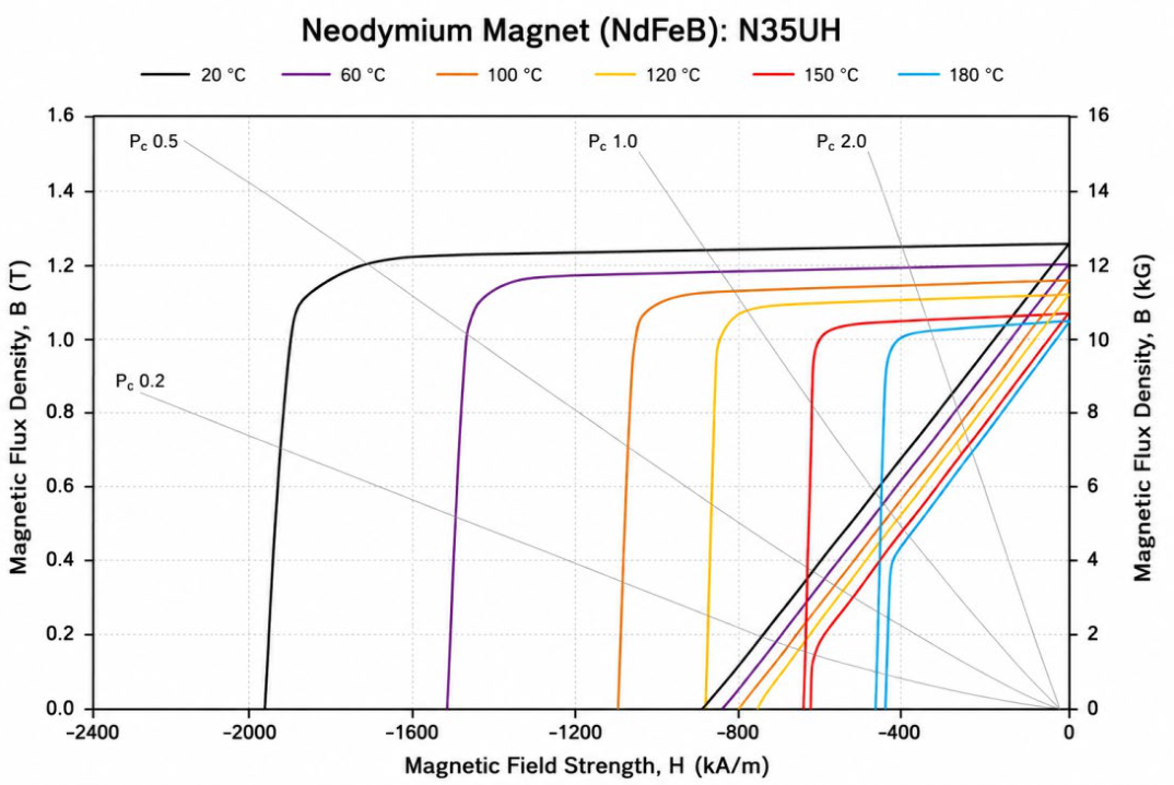
Figure 7.
Magnetic flux density (B) distribution for M400-50A (a) and Hiperco 50A (b) at 1000 rpm, and for M400-50A (c) and Hiperco 50A (d) at 12000 rpm , corresponding to the mechanical rotational speed of the inner rotor.
Figure 7.
Magnetic flux density (B) distribution for M400-50A (a) and Hiperco 50A (b) at 1000 rpm, and for M400-50A (c) and Hiperco 50A (d) at 12000 rpm , corresponding to the mechanical rotational speed of the inner rotor.
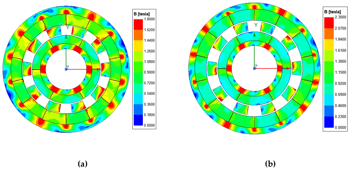
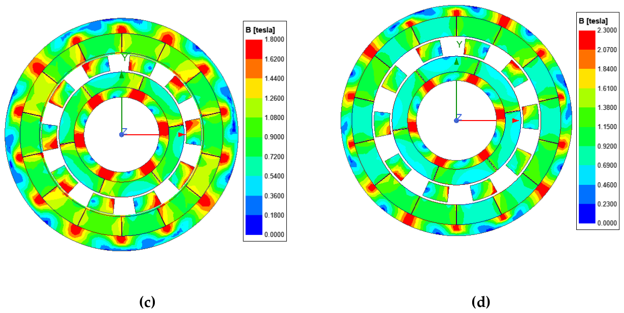
Figure 8.
Torque waveforms of the magnetic gear models: (a) M400-50A at 1000 rpm, (b) Hiperco 50A at 1000 rpm, (c) M400-50A at 12000 rpm, and (d) Hiperco 50A at 12000 rpm.
Figure 8.
Torque waveforms of the magnetic gear models: (a) M400-50A at 1000 rpm, (b) Hiperco 50A at 1000 rpm, (c) M400-50A at 12000 rpm, and (d) Hiperco 50A at 12000 rpm.
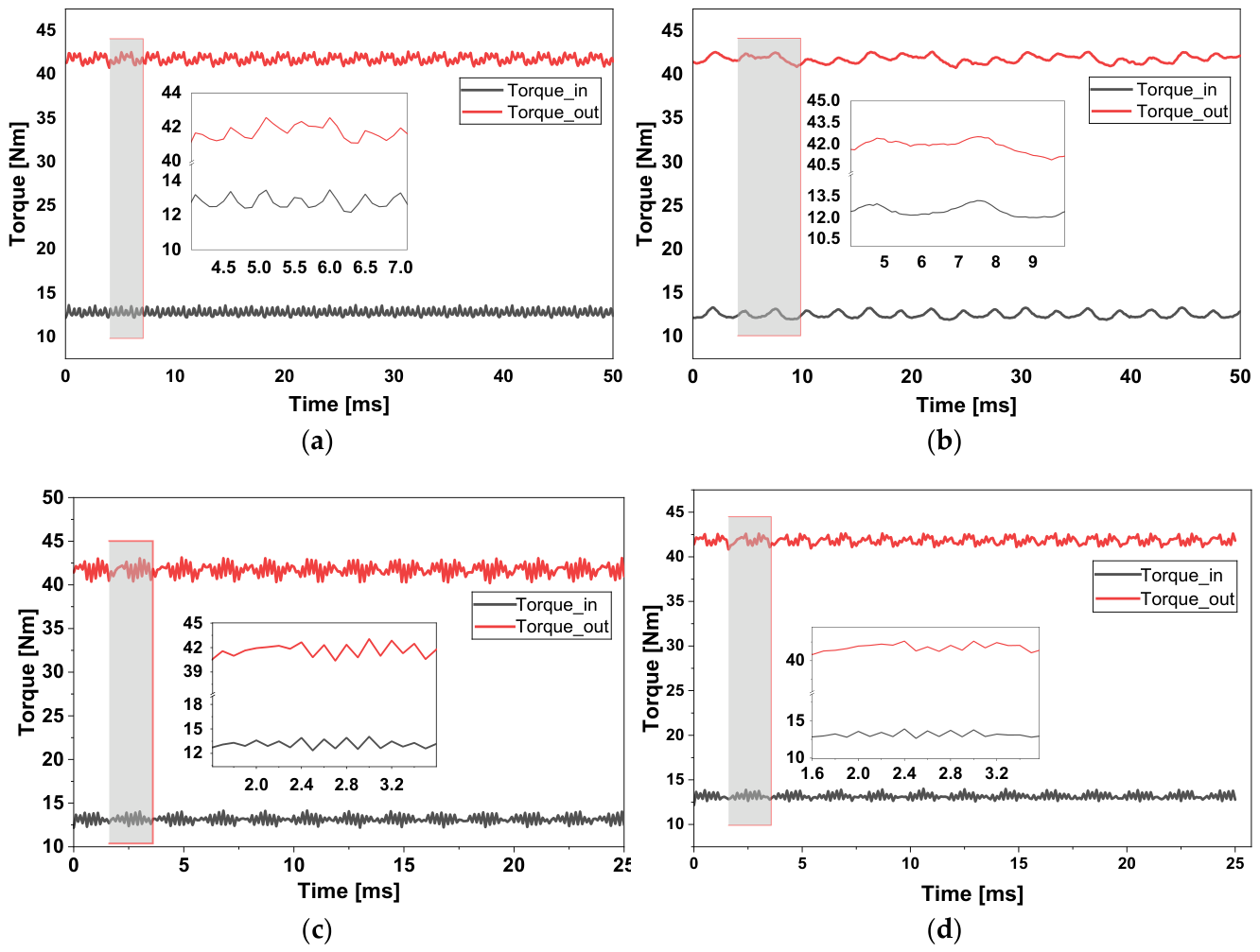
Figure 9.
Electromagnetic loss distributions of the magnetic gear models under low-speed (1000 rpm) and high-speed (12000 rpm) operating conditions: (a) M400-50A, (b) Hiperco 50A, (c) M400-50A, and (d) Hiperco 50A.
Figure 9.
Electromagnetic loss distributions of the magnetic gear models under low-speed (1000 rpm) and high-speed (12000 rpm) operating conditions: (a) M400-50A, (b) Hiperco 50A, (c) M400-50A, and (d) Hiperco 50A.
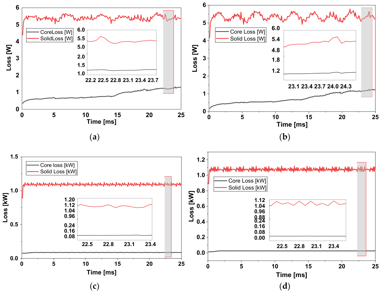
Figure 10.
Variation of (a) total losses and (b) efficiency of the magnetic gear models as a function of rotational speed.
Figure 10.
Variation of (a) total losses and (b) efficiency of the magnetic gear models as a function of rotational speed.
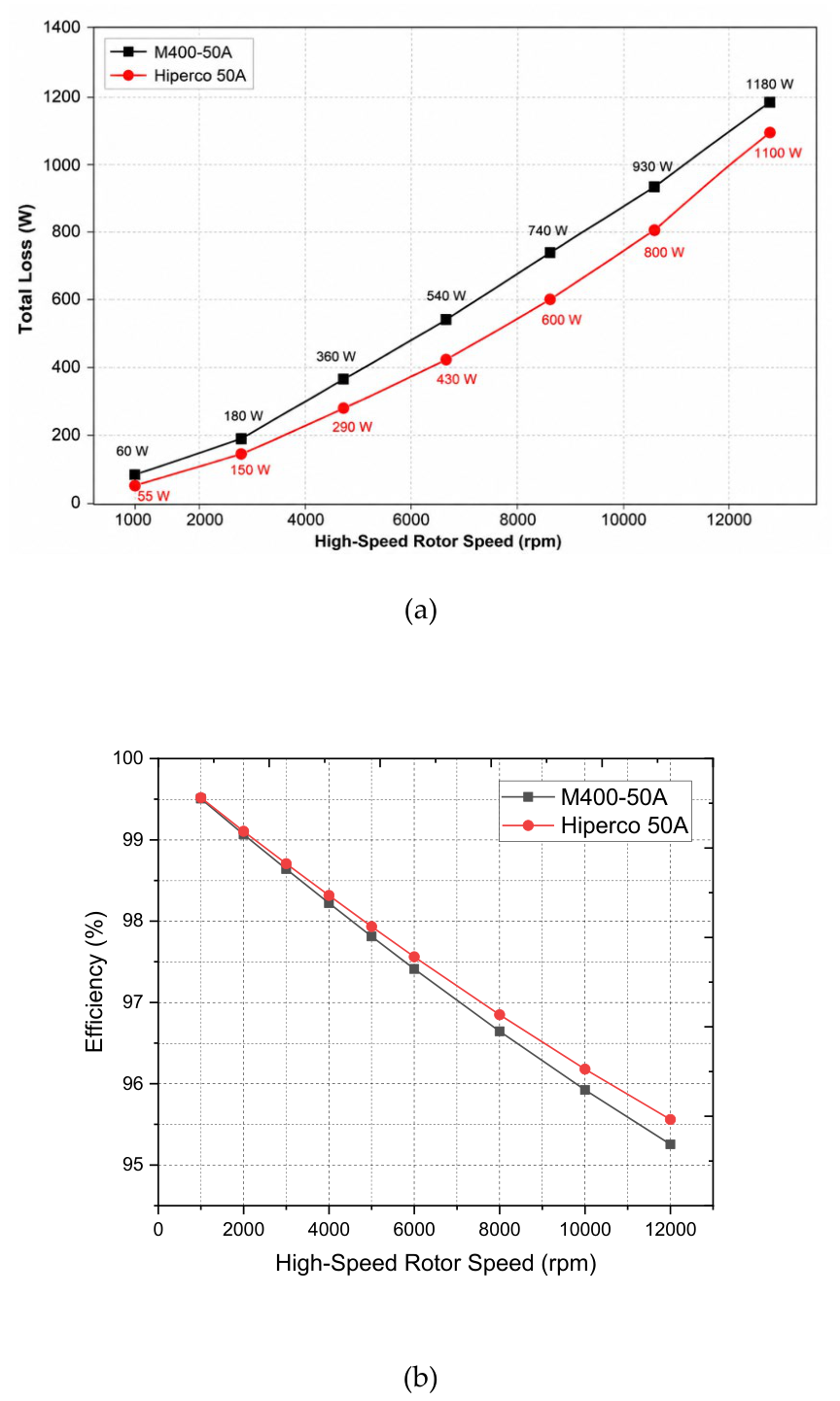
Figure 11.
Comparative temperature distribution of magnetic gear components under different operating speeds (1000 rpm and 12000 rpm).
Figure 11.
Comparative temperature distribution of magnetic gear components under different operating speeds (1000 rpm and 12000 rpm).
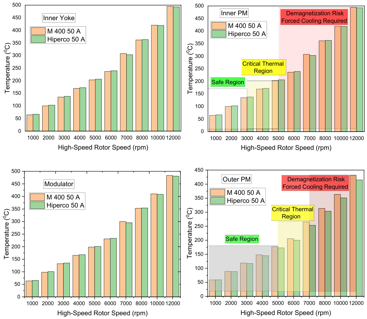
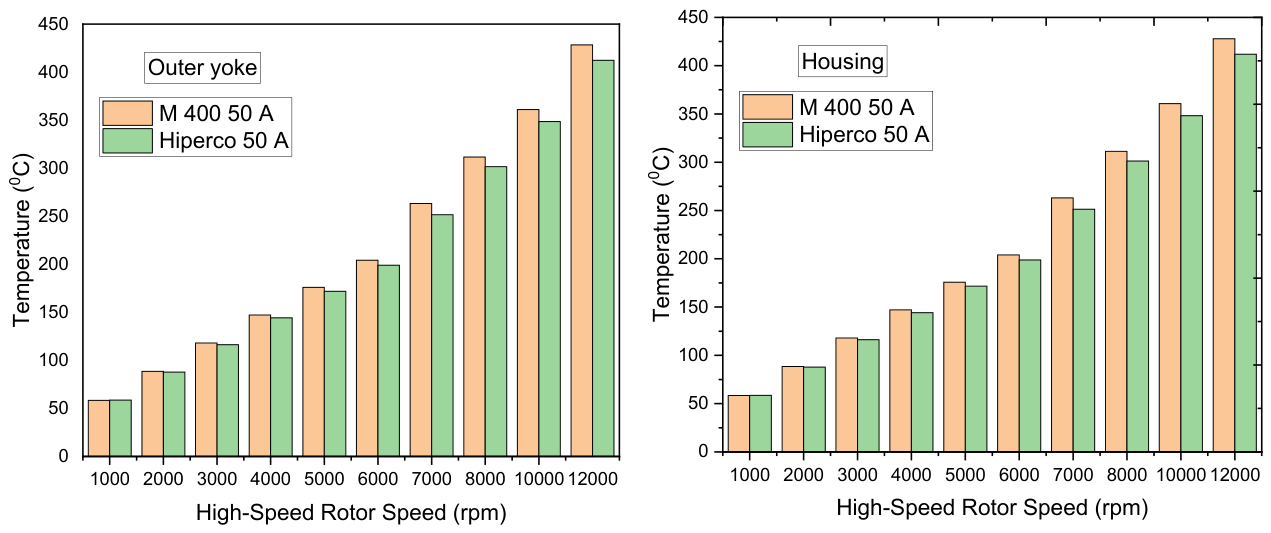
Figure 12.
Speed-dependent average temperature difference (ΔT) of Outer PM, Inner PM, and Modulator components for M400-50A and Hiperco 50A.
Figure 12.
Speed-dependent average temperature difference (ΔT) of Outer PM, Inner PM, and Modulator components for M400-50A and Hiperco 50A.
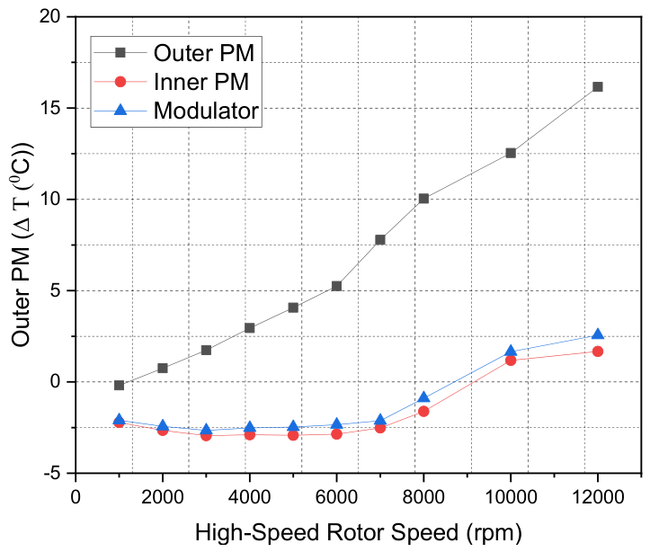
Figure 13.
Variation of temperature difference (ΔT) of the outer permanent magnet with high-speed rotor speed for M400-50A and Hiperco 50A.
Figure 13.
Variation of temperature difference (ΔT) of the outer permanent magnet with high-speed rotor speed for M400-50A and Hiperco 50A.
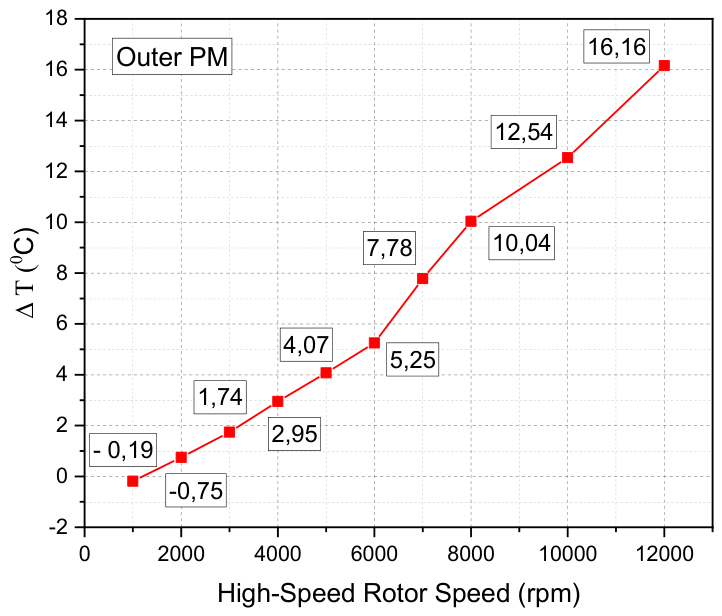
Figure 14.
Temperature distribution of magnetic gear components at 1000 rpm for both core materials (Top row: M400-50A, Bottom row: Hiperco 50A).
Figure 14.
Temperature distribution of magnetic gear components at 1000 rpm for both core materials (Top row: M400-50A, Bottom row: Hiperco 50A).
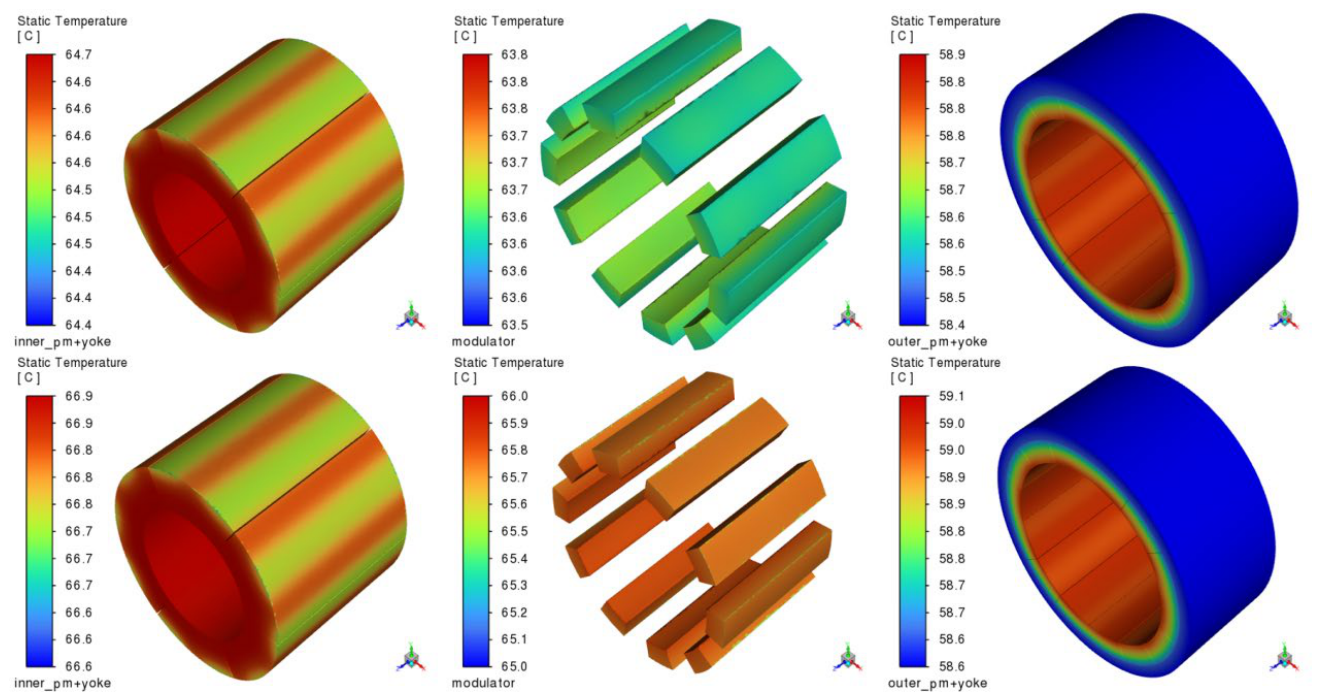
Figure 15.
Temperature distribution of magnetic gear components at high-speed operation (12000 rpm) for both core materials (Top row: M400-50A, Bottom row: Hiperco 50A).
Figure 15.
Temperature distribution of magnetic gear components at high-speed operation (12000 rpm) for both core materials (Top row: M400-50A, Bottom row: Hiperco 50A).
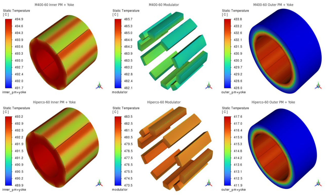
Figure 16.
Temperature distribution of magnetic gear components at low-speed operation (1000 rpm) for both core materials (Top row: M400-50A, Bottom row: Hiperco 50A) without eddy current losses.
Figure 16.
Temperature distribution of magnetic gear components at low-speed operation (1000 rpm) for both core materials (Top row: M400-50A, Bottom row: Hiperco 50A) without eddy current losses.
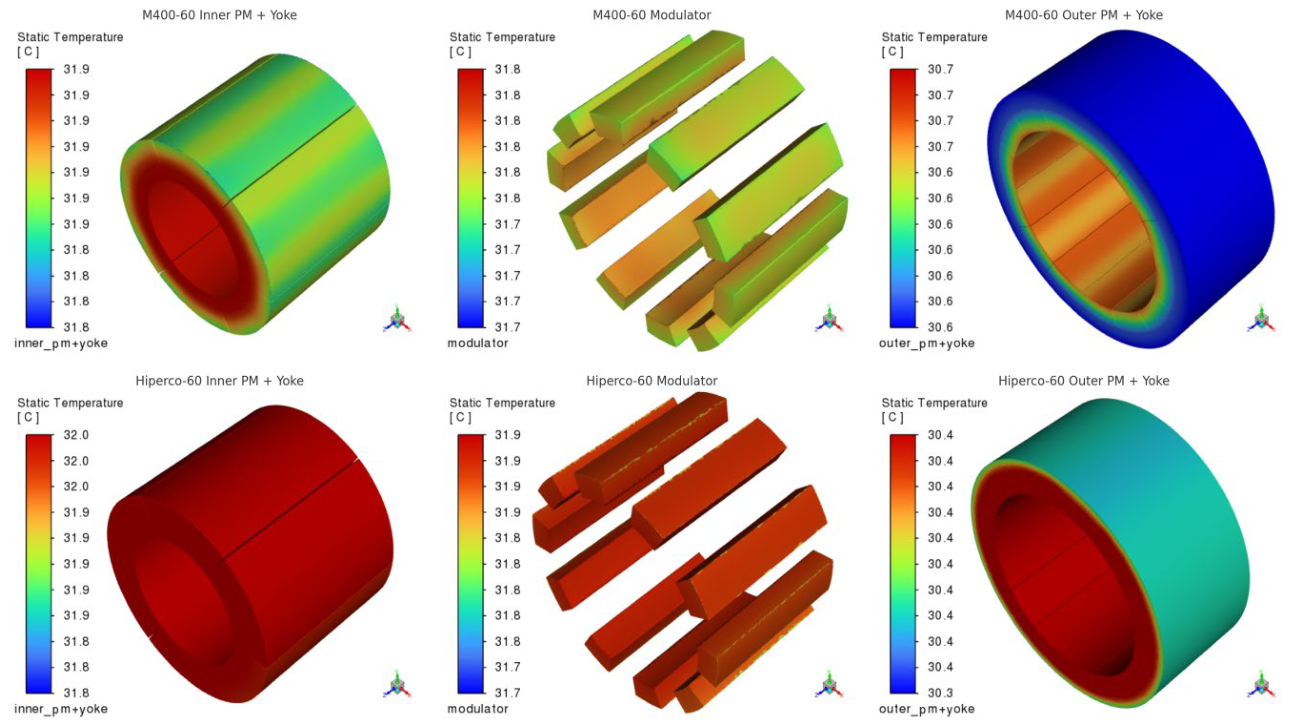
Figure 17.
Temperature distribution of magnetic gear components at high-speed operation (12000 rpm) for both core materials (Top row: M400-50A, Bottom row: Hiperco 50A) without eddy current losses.
Figure 17.
Temperature distribution of magnetic gear components at high-speed operation (12000 rpm) for both core materials (Top row: M400-50A, Bottom row: Hiperco 50A) without eddy current losses.
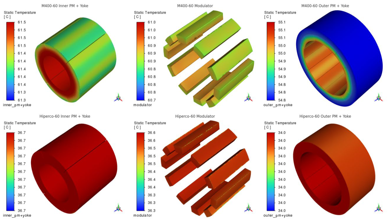
Figure 18.
Normalized electromagnetic and thermal performance comparison of M400-50A and Hiperco 50A models under low-speed (1000 rpm) and high-speed (12000 rpm) operating conditions based on multi-criteria evaluation.
Figure 18.
Normalized electromagnetic and thermal performance comparison of M400-50A and Hiperco 50A models under low-speed (1000 rpm) and high-speed (12000 rpm) operating conditions based on multi-criteria evaluation.
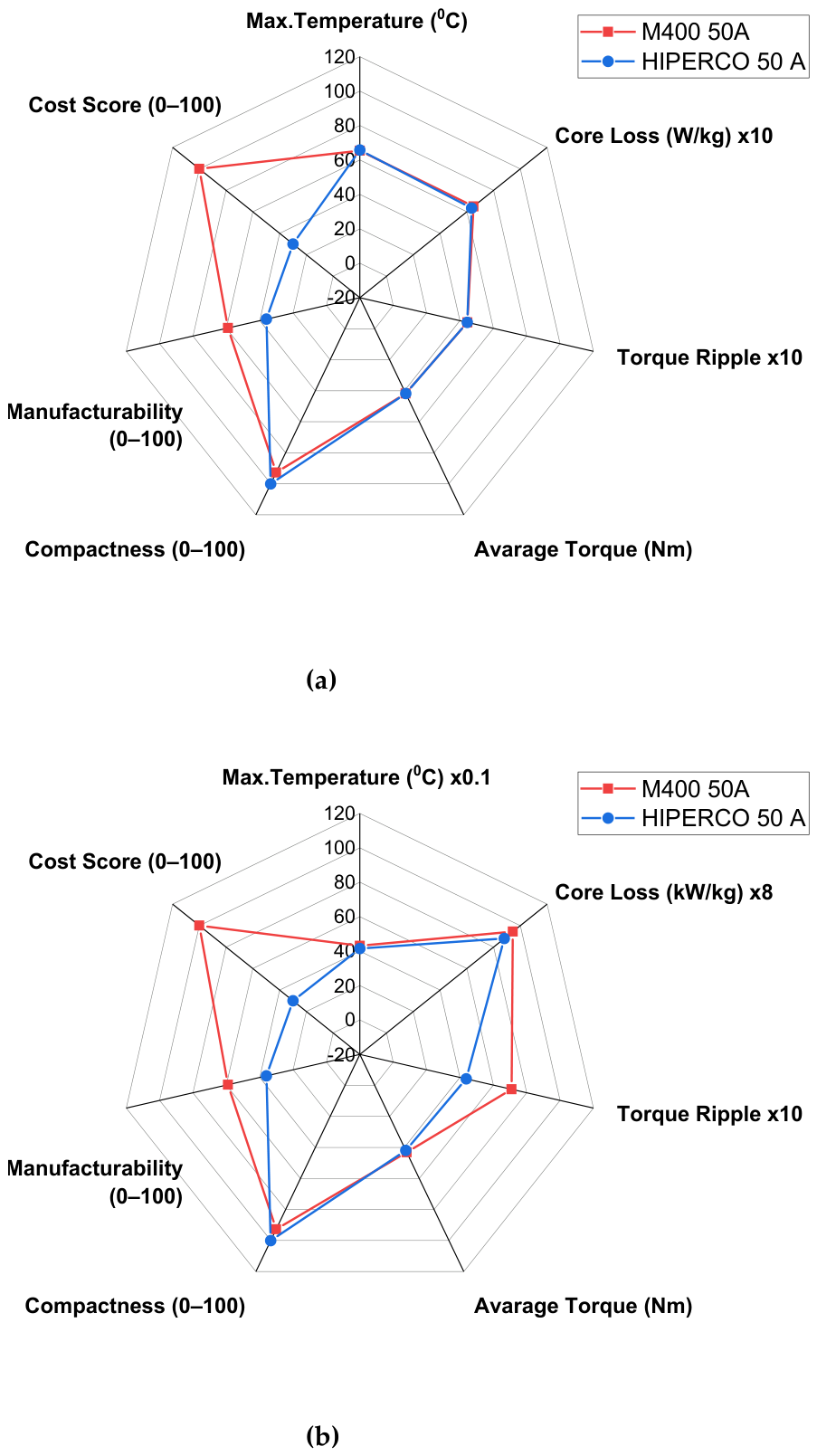

Table 1.
Comparative overview of Magnetic Gear focused studies.
| Study/Reference | System Type | Thermal Modelling Approach | Material Evaluation | Cooling Type | Contribution | ||
|---|---|---|---|---|---|---|---|
| Analytical Model | Numerical FEA | Experiment | |||||
| [17] Modaresahmadi, S. et al. | Laminated flux focusing MG | ✔ | ✔ | ✖ | ✖ | ✔ | A thermal analysis method that accounts for fluid behavior has been developed for magnetic gears. |
| [34] Sohrabzadeh, A. et al. | Reluctance MG | ✔ | ✔ | ✖ | ✖ | ✖ | Electromagnetic–thermal analysis of a reluctance magnetic gear, highlighting the impact of thermal effects on its performance and reliability. |
| [16] Desvaux, M. et al. | Concentric MG | ✔ | ✔ | ✖ | ✖ | ✔ | A model for loss and thermal analysis in a concentric magnetic gear for wind turbines has been presented to address cooling requirements. |
| [35] Zarghani, A. et al. | Transverse-radial flux MG | ✖ | ✔ | ✖ | ✖ | ✖ | Provides numerical FEA-based thermal analysis of a transverse–radial flux magnetic gear. |
| [8] Wong, H. Y. et al. | Halbach Coaxial MG | ✖ | ✔ | ✔ | ✖ | ✖ | demonstrated the suitability of the Halbach coaxial MG for aerospace applications through both numerical and experimental analyses. |
| [28] Mateev, V. et al | Coaxial MG | ✔ | ✔ | ✖ | ✖ | ✔ | Investigates the impact of viscous ferrofluid on cooling and performance in a low-speed coaxial magnetic gear. |
| [29] Gardner, M. C. et al. | Axial and Radial Coaxial MG | ✖ | ✖ | ✖ | ✖ | ✖ | comparative evaluation of the electromagnetic performance of surface-mounted axial and radial flux coaxial magnetic gears using analytical modeling and FEA |
| The proposed study | Coaxial MG | ✖ | ✔ | ✖ | ✔ | ✖ | Thermal improvement at high speeds through the use of materials with high thermal conductivity and saturation flux density. |
Table 2.
Parameters of the proposed CMG.
| Component | Parameter | Symbol | Unit | Model 1 | Model 2 |
|---|---|---|---|---|---|
| Inner Rotor | Yoke inner radius | IRiry | mm | 17.4 | 18 |
| Yoke outer radius | ORiry | mm | 22 | 22 | |
| PMs inner radius | IRirpm | mm | 22 | 22 | |
| PMs outer radius | ORirpm | mm | 29 | 29 | |
| Number of magnets | Nm1 | pcs | 6 | 6 | |
| Carrier | Carrier inner radius | IRc | mm | 30 | 30 |
| Carrier outer radius | ORc | mm | 37 | 37 | |
| Number of segments | Ns | pcs | 10 | 10 | |
| Centeral Angle | As | degree | 19.7 | 18 | |
| Outer Rotor | Yoke inner radius | IRory | mm | 47 | 47 |
| Yoke outer radius | ORory | mm | 54 | 52 | |
| PMs inner radius | IRorpm | mm | 38 | 38 | |
| PMs outer radius | ORorpm | mm | 47 | 47 | |
| Number of magnets | Nm2 | pcs | 14 | 14 | |
| Overall | Housing inner radius | IRh | mm | 54 | 52 |
| Housing outer diameter | ODh | mm | 124 | 120 | |
| Air gap | mm | 1 | 1 | ||
| Magnetic stack length | Lms | mm | 48 | 48 | |
| Overall axial length | Loa | mm | 180 | 180 | |
| Housing length | 99.5 | 99.5 |
| Materials | Property | Unit | Value |
|---|---|---|---|
| M400-50A | Density | kg/m3 | 7700 |
| Resistivity | µΩ.m | 0.52 | |
| Thermal conductivity | W/(m-K) | 28 | |
| Hiperco 50A | Density | kg/m3 | 8120 |
| Resistivity | µΩm | 0.42 | |
| Thermal conductivity | W/(m-K) | 32 | |
| NdFeB (N35UH) | Residual Magnetization | T | 1.15/1.20 |
| Coercive Force Relative Permeability |
kA/m - |
1590 1.05–1.1 |
|
| Density | kg/m3 | 7500 | |
| Maximum Operating Temp. | °C | 180 | |
| Curie Temperature | °C | 310-320 | |
| Electrical conductivity | kS/m | 660 |
Table 4.
Average Torque and Torque Ripple Values for Different Materials under Low- and High-Speed Operating Conditions.
Table 4.
Average Torque and Torque Ripple Values for Different Materials under Low- and High-Speed Operating Conditions.
| Speed (rpm) |
Material | Average Torque_in (Nm) |
Average Torque_out (Nm) |
Torque Ripple (%) |
|
|---|---|---|---|---|---|
| 1000 | M400-50A | 12.65 | 41.76 | 4.45 | |
| Hiperco 50A | 12.43 | 41.81 | 4.41 | ||
| 12000 | M400-50A | 14.15 | 43.14 | 7.09 | |
| Hiperco 50A | 13.02 | 41.85 | 4.38 |
Disclaimer/Publisher’s Note: The statements, opinions and data contained in all publications are solely those of the individual author(s) and contributor(s) and not of MDPI and/or the editor(s). MDPI and/or the editor(s) disclaim responsibility for any injury to people or property resulting from any ideas, methods, instructions or products referred to in the content. |
© 2026 by the authors. Licensee MDPI, Basel, Switzerland. This article is an open access article distributed under the terms and conditions of the Creative Commons Attribution (CC BY) license (http://creativecommons.org/licenses/by/4.0/).
Copyright: This open access article is published under a Creative Commons CC BY 4.0 license, which permit the free download, distribution, and reuse, provided that the author and preprint are cited in any reuse.


