

Submitted:
19 May 2026
Posted:
20 May 2026
You are already at the latest version
Abstract
The pronounced aero-hydrodynamic coupling effects of modern Wind-Assisted Propulsion System (WAPS) ships challenge the applicability of traditional stability frameworks, which are predicated on hydrostatic energy balance, in satisfying the dynamic constraints of the Second Generation Intact Stability Criteria (SGISC). This paper systematically reviews the methodological evolution of dynamic stability assessments for WAPS ships under extreme and damaged conditions. By introducing a "Hierarchy of Evidence" evaluation framework, this study delineates the applicability boundaries of aerodynamic Reduced-Order Models (ROM), extended 3/4-DOF maneuvering equations, and 6-DOF time-domain hybrid architectures, defining the role of high-fidelity CFD-VPP in establishing calibration benchmarks. The review also discusses the damping distortion mechanisms induced by multiphase flow sloshing under damaged conditions. Synthesized findings indicate that transitioning towards a 6-DOF time-domain coupled architecture provides clear advantages for capturing unsteady aerodynamic hysteresis and nonlinear interference. Meanwhile, surrogate models, such as Physics-Informed Neural Networks (PINNs), offer a potential pathway to mitigate the computational demands associated with long-term extreme value extrapolations. Ultimately, this review provides a methodological reference for the high-fidelity assessment of WAPS and the development of Digital Twin systems.
Keywords:
wind‐assisted propulsion systems (WAPS)
; Second generation intact stability criteria (SGISC)
; time‐domain simulation
; 6‐DOF strongly coupled model
; damaged stability
; physics‐informed neural networks (PINNs)
1. Introduction
1.1. Decarbonization Context in Shipping and Multi-Physics Challenges of WAPS
Driven by escalating global climate change and stringent greenhouse gas (GHG) emission constraints, the International Maritime Organization (IMO) has progressively implemented a suite of mandatory regulations, including the Energy Efficiency Design Index (EEDI), the Energy Efficiency Existing Ship Index (EEXI), and the Carbon Intensity Indicator (CII). Amidst this decarbonization trajectory, Wind-Assisted Propulsion Systems (WAPS), leveraging their capacity to directly harvest offshore renewable wind energy, have emerged as one of the most promising candidate pathways for enhancing the energy efficiency of operational vessels [1].
Figure 1.
Typical engineering applications of modern Wind-Assisted Propulsion Systems (WAPS) on commercial ships. (Image from [1]).
Figure 1.
Typical engineering applications of modern Wind-Assisted Propulsion Systems (WAPS) on commercial ships. (Image from [1]).
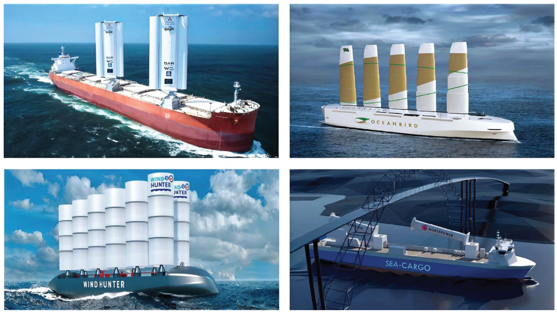
However, the geometric scale and aerodynamic characteristics of modern WAPS-equipped commercial vessels substantially surpass those of traditional experimental sailing yachts. The integration of macro-structures, such as large rigid wingsails and rotor sails, fundamentally alters the global force distribution of the vessel. Under extreme sea states, these structural characteristics are highly susceptible to inducing complex, coupled wind-wave excitations. As large-inertia commercial vessels undergo severe oscillation in waves, the spatio-temporal transients in relative wind velocity precipitate pronounced aerodynamic hysteresis. Concurrently, the leeway angle—necessitated to counterbalance the aerodynamic side force—provokes asymmetric distortion within the hull’s wake field. This strong coupling effect within the aero-hydrodynamic two-phase flow field imposes formidable multi-physics challenges on the prediction of dynamic responses and the assurance of navigational safety under adverse sea conditions.
1.2. Methodological Limitations of Traditional Frameworks and the Transition to SGISC
For decades, the statutory approval of intact stability has predominantly relied on quasi-static frameworks, notably the 2008 IS Code [2]. Such regulations evaluate energy balance based on steady wind pressure and hydrostatic restoring forces. Although extensively adopted for conventional low-windage vessels, the quasi-static assumption may face limitations in accurately defining dynamic capsizing boundaries when evaluating the unsteady energy dissipation and transient large-angle motions of WAPS ships. To address these limitations, the IMO established the Second Generation Intact Stability Criteria (SGISC), introducing physical constraints on five dynamic stability failure modes [3]. Within the SGISC architecture, the propensity of large-area sails to trigger conservative penalties in preliminary screening often necessitates Direct Stability Assessment (DSA) for WAPS vessels. DSA requires nonlinear time-domain simulations to evaluate extreme responses, driving an important methodological shift from low-degree-of-freedom (DOF) Maneuvering Modeling Group (MMG) models towards 6-DOF time-domain coupled models that include Coriolis cross-coupling terms.
1.3. Research Motivation and the Formulation of a “Hierarchy of Evidence” Framework
Ensuring the survivability of WAPS-equipped vessels under extreme and damaged scenarios is a prerequisite for their large-scale commercial viability. While current research predominantly focuses on single-dimensional analyses—such as utilizing Computational Fluid Dynamics (CFD) for sail thrust optimization or 3/4-DOF weather routing for fuel estimation—systematic reviews delineating the applicability boundaries of various nonlinear assessment models within the SGISC framework remain conspicuously scarce. As research pivots towards high-fidelity 6-DOF CFD-VPP architectures and Artificial Intelligence (AI) surrogate models, objectively demarcating methodological reliability is urgently required to prevent biased technical expectations in computational resource allocation. Drawing inspiration from evidence-grading philosophies [4,5] and ASME V&V 20 standards [6], this review introduces a “Hierarchy of Evidence” framework (Figure 2) to strictly stratify existing WAPS stability methodologies:
(1)Strong Evidence (Level A): Ground truth derived from high-standard wind tunnel tests, free-running model tests in towing tanks, and full-scale trials, authentically capturing full-physics aero-hydrodynamic interference.
(2)Moderate Evidence (Level B): High-fidelity numerical validation (e.g., URANS, DES, or CFD-VPP) that departs from linear assumptions to explicitly resolve unsteady stall hysteresis, wake distortion, and multiphase flow sloshing in damaged compartments.
(3)Weak Evidence (Level C): Baseline models predicated on potential flow theory, empirical formulas (e.g., traditional 3/4-DOF MMG models), and 1-DOF quasi-static energy balance equations, offering high computational economy but exhibiting theoretical limitations under extreme nonlinear boundaries.
The remainder of this paper is organized as follows. Section 2, Section 3, Section 4 and Section 5 review the methodological progression from quasi-static regulations to 6-DOF time-domain hybrid architectures. Section 6 examines dynamic instability modes within the SGISC framework. Section 7 extends the discussion to damaged-condition survivability. Section 8 discusses the emerging role of Physics-Informed Neural Networks (PINNs) and Digital Twins in overcoming computational bottlenecks. Section 9 concludes by outlining a progressive methodological strategy for WAPS stability assessment. Figure 3 summarizes the historical methodological evolution and the associated multi-physics coupling roadmap.
2. Methodological Evolution and Horizontal Comparison of Stability Regulatory Frameworks
For large commercial vessels equipped with Wind-Assisted Propulsion Systems (WAPS), the towering aerodynamic structures generate intricate coupling effects with traditional hull hydrodynamics. Confronted with such multi-physics interactions, the assessment logic of current stability regulations is undergoing a transition from empirical quasi-static frameworks to fully time-domain dynamic assessments. Objectively delineating the treatment logic, degree of conservatism, and applicability boundaries of various assessment frameworks for WAPS ships is a crucial prerequisite for establishing the trajectory of subsequent time-domain modeling.
2.1. Physical Simplifications in Traditional Quasi-Static Regulations and Empirical Formulas
For decades, intact stability assessments within the maritime sector have predominantly relied on the Weather Criterion stipulated in the International Code on Intact Stability, 2008. During the nascent stages of wind-assisted ship research, academia largely gravitated towards seeking engineering compromises within static or semi-empirical frameworks. For instance,[7] proposed a design methodology that inversely calculates the maximum sail area based on static stability criteria, attempting to establish an empirical correlation between sail area and displacement. [8] introduced roll-damping influence coefficients for sails and daggerboards when calculating the roll angle, thereby facilitating static verification under conventional regulations. Consequently, these early assessment methodologies generally simplify wind loads into steady mean wind pressures. When confronting the intricate dynamic fluid interactions inherent to modern, massive WAPS commercial vessels, their theoretical tolerance for transient extreme responses remains relatively constrained.
2.2. Treatment Logic and Applicability Boundaries of Quasi-Static Assessment Frameworks in WAPS Scenarios
Current WAPS-related guidance issued by classification societies remains largely rooted in the quasi-static logic of conventional intact stability criteria. Building on the 2008 IS Code and related weather-criterion practice, these frameworks mainly assess restoring lever, stability-curve area, and wind-heeling effects through static or semi-empirical corrections, while additional WAPS-specific rules have been introduced by major institutions such as EMSA, DNV, ABS, Lloyd’s Register, ClassNK, BV, RINA, KR, and REG [9,10,11,12,13,14,15,16,17,18,19]. Although these rules differ in details across jurisdictions, their common objective is to extend traditional intact-stability approval to WAPS through conservative quasi-static adjustments.
In essence, this first-generation logic still relies on three simplifications. First, natural wind fields and gusts are commonly reduced to steady or profile-based inputs, which cannot fully represent transient atmospheric fluctuations in severe sea states [20]. Second, the mapping from wind pressure to heeling moment is typically expressed through empirical attenuation formulas, such as or , which were originally developed for simplified sail or windage representations and may be insufficient for modern WAPS operating under large heel angles and unsteady inflow [20,21]. Third, damping and energy dissipation are treated mainly through quasi-static restoring-energy balance, whereas modern WAPS ships experience time-varying aerodynamic damping, transient restoring-force variations, and multi-DOF wind–wave coupling that cannot be fully represented within static hydrostatic formulations.
These limitations do not negate the engineering value of quasi-static criteria for preliminary screening and compliance checks. However, they do indicate that first-generation intact stability logic becomes increasingly restrictive for modern WAPS commercial ships, especially under extreme sea states and large-amplitude motions. This limitation provides the rationale for the transition toward the SGISC framework and Direct Stability Assessment, where dynamic failure modes must be evaluated using higher-fidelity time-domain approaches.
2.3. The SGISC Multi-Tiered Assessment Architecture and DSA Implementation
To supplement the inadequacies of traditional static regulations in predicting dynamic instability, the IMO established the SGISC, providing physical constraints against five quintessential dynamic stability failure modes: dead ship condition, pure loss of stability, parametric rolling, broaching-to, and excessive acceleration [22]. Studies on the implementation of SGISC guidelines [3] demonstrate that this standard furnishes a systematic, multi-tiered framework for evaluating the dynamic vulnerability of ships in complex waves.
Under the SGISC architecture, vessels are initially required to undergo statutory Level 1 and Level 2 vulnerability screenings. Application case studies [23] indicate that vessels possessing a high aerodynamic center of gravity and a massive lateral windage area often fail to pass screenings for parametric rolling and pure loss of stability—based on simplified wave theory—due to the inherent conservatism of the regulations. This inevitably drives the assessment process towards the third tier: DSA.
As a high-fidelity evaluation pathway, the reliability of DSA is critically contingent upon the fidelity of the numerical tools employed. While discussing the validation of DSA codes within the SGISC framework, [24,25] posit that introducing 6-DOF blended time-domain codes and subjecting them to rigorous benchmark validation is the core prerequisite for establishing the credibility of direct assessments. Furthermore, DSA is not merely about outputting time-domain responses; recent research by [26] on DSA post-processing procedures emphasizes the necessity of transforming time-domain extremes into specific failure probabilities and operational guidance via rigorous statistical extrapolation and post-processing. This closed-loop approach, bridging time-domain solvers to probabilistic post-processing, renders DSA one of the more rigorous practical pathways for verifying the survivability of WAPS vessels under extreme conditions.
2.4. Horizontal Comparison of Current Stability Frameworks and Summary of Assessment Positioning
Table 1 compares the core logic, applicability, and limitations of current stability frameworks for WAPS assessment. While quasi-static regulations, including the 2008 IS Code and classification-society guidelines, provide computationally efficient baseline evidence for preliminary screening, their underlying energy-balance assumptions limit predictive fidelity for large-scale WAPS. This limitation is reflected in three main methodological dimensions:
(1) Empirical aerodynamic attenuation. Traditional standards rely on fixed algebraic corrections for the wind heeling lever, which are often inadequate for representing the highly nonlinear moment distributions of modern WAPS, such as rigid wingsails and rotor sails, across varying heel angles and angles of attack.
(2) Quasi-steady aerodynamic treatment. Approximating sails as constant windage areas neglects unsteady effects, including dynamic stall and alternating Magnus forces, and does not explicitly account for the nonlinear aerodynamic roll damping induced by WAPS in static stability assessments.
(3) Roll-only dimensional reduction. Current criteria predominantly assess roll as a single degree of freedom, which obscures the coupled sway–yaw–roll interactions generated by large aerodynamic side forces in realistic operating conditions.
Although Table 1 abstracts a generalized industry consensus, and specific penalty coefficients and restoring-lever thresholds still vary across jurisdictions (Table 1), the continued reliance on quasi-static conservatism may impose excessive penalties on some innovative WAPS configurations. This trade-off between computational efficiency and physical fidelity supports a methodological shift toward multi-DOF time-domain coupled models, particularly for high-risk dynamic scenarios under the SGISC DSA framework.
3. Unsteady Aerodynamics of Modern WAPS and Boundaries of Reduced-Order Modeling
Under extreme sea states, the dynamic response of wind-assisted commercial ships relies heavily on the real-time interaction between aerodynamic and hydrodynamic loads. Traditional stability criteria typically simplify wind loads into quasi-steady states. However, satisfying fully time-domain strongly coupled DSA assessments necessitates models that accurately reflect the transient evolution of aerodynamic forces within complex wind fields [27].
Recently, high-fidelity Computational Fluid Dynamics (CFD) has been extensively employed to resolve the microscopic flow characteristics of specific WAPS, such as the Magnus hysteresis of rotor sails [28,29], 3D vortex shedding of rigid wingsails [30,31], and wake velocity deficits in multi-sail arrays [32], as well as the periodic aerodynamic load signatures and routing energy-saving contributions of towing kites under dynamic flight trajectories [33,34]. These high-resolution studies furnish critical input boundaries for full-ship 6-DOF time-domain models; simultaneously, they highlight that if complex aerodynamic forces are continually simplified into static coefficients during ship-level stability assessments, the models will fail to represent transient hysteresis and peak responses in authentic sea states.
3.1. Limitations of Steady-State Aerodynamic Coefficients and Unsteady Hysteresis Effects
Industry currently relies heavily on static polar coefficients extracted from wind tunnel tests or steady RANS CFD for algebraic interpolation. However, as massive commercial vessels undergo severe oscillation in adverse waves, the transients of relative wind speed and direction precipitate pronounced aerodynamic hysteresis. Steady-state algebraic methods typically smooth out the transient peaks and phase lags of aerodynamic forces.
Field research by [35,36] on rigid wingsails confirms that the spatio-temporal distribution of surface pressure is highly unsteady. As illustrated in Figure 4, under extreme gust excitations, the unsteady hysteresis loop significantly deviates from the quasi-static linear assumption. This indicates that relying solely on static coefficient interpolation may mask the system’s potential physical capsizing risks.
3.2. Aerodynamic Specificities of Diverse Sail Configurations and Multi-Sail Interference
Under substantial attitude perturbations, modern WAPS commercial ships exhibit strongly unsteady aerodynamic behavior driven by flow separation and wake interference. For single rigid wingsails, unsteady RANS simulations of crescent-shaped profiles by [31] show that three-dimensional tip vortices at the sail edges can affect propulsive performance, which places higher fidelity requirements on the evaluation of dynamic sail loads. In multi-sail arrays, wake shadowing from windward sails modifies the inflow to leeward sails. [32,38] show that the wake of forward sails reduces suction-side negative pressure on aft sails and introduces a velocity deficit, leading to a reduction in overall thrust. To capture these vortex-dominated interactions, recent studies have increasingly employed higher-order numerical methods such as Detached Eddy Simulation (DES) or Large Eddy Simulation (LES) [39], or have optimized sail-array layouts using CFD [40]. Together, these studies provide higher-order physical evidence for the nonlinear aerodynamic damping associated with ship rolling.
Existing studies also indicate that different WAPS configurations affect roll damping and dynamic stability margins through different mechanisms:
(1) Rigid wingsails: [41] suggest that their large windage area can provide aerodynamic roll damping and help suppress resonance responses in waves. However, their elevated installation height and strong static wind heeling moments may reduce the vessel’s inherent stability margin.
(2) Flettner rotors: In addition to steady wind loads, rotating cylinders may generate gyroscopic effects and unsteady Magnus-lift fluctuations under ship angular motions [27,42]. These effects may introduce nonlinear alternating damping terms into the roll equation.
(3) Towing kites: As flexible systems deployed at high altitude with negligible self-weight, towing kites have little influence on the ship’s static center of gravity. However, gust-induced tether tension can produce impulsive heeling moments [43], which may challenge transient restoring capacity under extreme sea states.
Because these physical mechanisms differ across sail types, their aerodynamic effects cannot be represented adequately by a single empirical coefficient. A more consistent approach is to introduce configuration-specific aerodynamic parameters explicitly as state-dependent inputs in ship dynamic equations, thereby improving the prediction of coupled wind–wave responses.
3.3. Engineering Positioning of ROM and the Indicial Response Method
Because directly invoking 3D CFD for tens of hours of Monte Carlo integration faces prohibitive computational bottlenecks [44], introducing physically interpretable Reduced-Order Models (ROM) is an engineering necessity.
The Indicial Response Method (IRM) utilizes the Duhamel integral to express transient aerodynamic forces as a convolution of the initial state and the angle-of-attack variation history. When applied to commercial ships, its physical boundaries must be clarified: since the colossal mass inertia of giant vessels constitutes a natural low-pass filter, IRM is primarily used to quantify the local memory effects of aerodynamic hysteresis during long-period wave encounters. Furthermore, IRM fidelity may degrade under deep dynamic stall. Thus, IRM is optimally positioned as an efficient kernel for probabilistic stability screening, while extreme operational points still necessitate baseline calibration via high-fidelity CFD.
3.4. Section Summary: Applicability Scope, Evidence Strength, and Research Gaps
Within the evidence-stratification paradigm, high-fidelity CFD and physical measurements provide strong evidence for resolving unsteady aerodynamic mechanisms, including flow separation, wake interaction, and vortex evolution, but remain computationally prohibitive for full-lifecycle time-domain simulations. Reduced-order models (ROMs), such as the indicial response method (IRM), therefore provide moderate evidence by balancing physical fidelity and computational efficiency, making long-duration assessment and probabilistic stability screening feasible. However, because these models rely on fluid-dynamic decoupling assumptions, their error bounds under deep dynamic stall conditions remain insufficiently quantified, and continued cross-validation against high-fidelity CFD benchmarks is still required.
4. Nonlinear Hydrodynamic Interferences Under Leeway and Modeling Comparisons
To balance the aerodynamic side force generated by sails, vessels must navigate with a leeway angle in crosswinds. Delineating the applicability boundaries of different hydrodynamic assessment models in processing this asymmetric flow field is crucial for constructing high-fidelity simulations.
4.1. Hydrodynamic Boundary Divergence Between Large-Inertia Commercial Ships and Traditional Sailing Yachts
While traditional sailing yacht stability regulations rely on deep extended keels and bottom ballast to provide principal hydrodynamic lift and nonlinear roll damping against aerodynamic side forces [45,46,47], modern WAPS commercial ships exhibit fundamentally different hydrodynamic boundaries. Constrained by draft requirements, these massive, flat-bottomed vessels lack the effective lateral blockage of deep keels. Consequently, their immense mass inertia couples strongly with wingsail lift under lateral wind and wave action, inducing rolling motions with pronounced constant heel angles [48].
This divergence mandates an independent mechanistic framework: although 1-DOF Performance Prediction Programs (PPP) offer high computational efficiency for preliminary conceptual evaluations, their inability to adequately encompass leeway-induced added resistance and rudder drag leads to notable deviations in fuel-saving predictions under specific sail scales [49,50]. Therefore, when assessment objectives involve large heel angles and markedly asymmetric flow fields, extending to high-dimensional dynamic models (encompassing sway, yaw, and roll) becomes a baseline necessity.
4.2. “Hull-Propeller-Rudder” Fluid-Dynamic Coupling Distortion Under Leeway Conditions
Under leeway conditions, the stern wake of a WAPS commercial ship becomes asymmetric, which limits the applicability of hydrodynamic derivatives obtained under straight-ahead conditions. High-fidelity CFD studies at both model and full scale, including the DES analysis of [51] and the motion analysis of fully wind-powered ships by [41], show that even small leeway angles can alter the hull-surface pressure distribution asymmetrically. [52] further showed that leeway induces lateral free-surface disturbances on the windward and leeward sides, which promote cross-flow separation on appendages operating at higher effective angles of attack.
To maintain course under aerodynamic side force, WAPS commercial ships usually require a corrective rudder angle. This creates nonlinear hull–propeller–rudder interaction because the propeller operates in an asymmetric inflow while the rudder works at a relatively large angle. Free-running basin tests by [53] show that changes in rudder angle and propeller load can produce nonlinear variations in total resistance and lateral moment. These results indicate that hydrodynamic derivatives used in performance prediction should account explicitly for leeway and rudder-angle interference. More broadly, recent studies suggest that leeway and appendage interaction can generate additional sail-induced resistance and modify nonlinear damping and propulsive efficiency in waves. Figure 5 summarizes the corresponding asymmetric force-balance mechanism: to balance sail side force, the ship develops both leeway and rudder correction, which in turn distort the wake and promote additional cross-flow separation.
The asymmetric wake also changes the propeller inflow and strengthens maneuvering–propulsion interaction. To quantify this effect, viscous-flow solvers are increasingly used to examine the relationship between resistance and yaw angle. As shown in Figure 6, numerical studies have reported a nonlinear increase in hydrodynamic resistance with yaw angle [52]. This suggests that the conventional linear assumption for small leeway angles may be insufficient for WAPS ships, and that higher-dimensional interference matrices may be needed in performance-prediction models.
4.3. Extension of MMG Models for WAPS Commercial Ships and Their Mathematical Limitations
To capture leeway-induced interference, recent studies have incorporated sail aerodynamic matrices into conventional MMG models. [54] proposed a numerical design method for wind-assisted ships by coupling nonlinear hull hydrodynamic coefficients with sail thrust models and solving the sway–yaw equilibrium, including the relationship between leeway angle and propeller thrust. Similarly, [55] developed a 3-DOF MMG model for wingsail-assisted commercial ships that incorporates sail thrust and lateral forces.
where , , and denote the surge velocity, sway velocity, and yaw angular velocity, respectively; the subscripts , and represent fluid inertial forces, hull viscous hydrodynamic forces, propeller forces, rudder forces, and sail aerodynamic forces, respectively. By introducing high-order hydrodynamic coefficients predicated on sway velocity and yaw rate , such models can, to a certain extent, adequately predict the dynamic interference of sails on leeway angles and rudder effectiveness.
Their predictive performance, however, depends on the availability of hydrodynamic derivatives under realistic operating conditions. To address the limitations of empirical formulas at large leeway angles, CFD-based test matrices have been used to extract sail-induced resistance and hydrodynamic derivatives. [56], for example, showed that properly designed CFD matrices can quantify the viscous added resistance induced jointly by yaw and heel. These parameterized datasets improve MMG boundary fidelity and also support the development of more consistent CFD-VPP toolchains.
Nevertheless, 3-DOF and 4-DOF MMG models remain primarily horizontal-plane maneuvering models and usually decouple heave and pitch. [57] showed that vertical motions in waves can produce substantial time variation in the waterplane moment of inertia. This limits the ability of decoupled MMG models to represent failure modes such as parametric rolling, which depend strongly on transient waterplane variations within the SGISC framework. To address this limitation, recent studies have explored time-domain architectures that couple unsteady CFD solvers with 6-DOF rigid-body dynamics. Although these high-dimensional models were first developed mainly for racing yachts [58], they provide a useful methodological reference for DSA-oriented assessment of WAPS commercial ships in extreme seas.
4.4. Horizontal Comparison of Hydrodynamic Modeling Tiers and Summary of Evidence
To explicitly delineate the physical boundaries of diverse hydrodynamic models in WAPS vessel assessments, this section conducts a systematic horizontal comparison and critical analysis of existing modeling tiers (see Table 2).
As literature surveys reveal, prediction models of varying dimensions exhibit pronounced trade-offs between physical fidelity and computational cost across disparate application scenarios. Specifically, while low-DOF empirical models (1/3-DOF) offer exceptional computational efficiency for rapid compliance screening during conceptual design, their over-reliance on conventional hull extrapolations renders them inadequate for capturing unsteady sail-induced resistance under large leeway angles (furnishing only baseline evidence). Conversely, extended 3/4-DOF MMG models—currently the most extensively applied medium-order models—effectively process quasi-steady aero-hydrodynamic interferences at reasonable costs for weather routing; nevertheless, their motion decoupling assumptions frequently precipitate physical distortions when processing wave radiation memory effects and severe vertical motions under extreme sea states. Ultimately, by introducing vertical motion coupling and full flow-field resolution, high-fidelity 6-DOF hybrid models and CFD-VPP accurately quantify the strong coupling between aerodynamic phase hysteresis and nonlinear wave excitations. Despite their direct application in long-term voyages being bottlenecked by prohibitive computational costs, they play an irreplaceable role in delineating extreme instability boundaries and establishing cross-validation benchmarks.
The synthesis in this section demonstrates that the transition from the extended 3/4-DOF to the 6-DOF time-domain architecture is not a mere accretion of numerical dimensions. Rather, it is a physical necessity to bridge the strongly nonlinear coupling effects emerging between the propulsion system and the ship’s heave and pitch motions under extreme irregular waves—directly constituting the methodological motivation for introducing the 6-DOF time-domain architecture in Section 5.
5. 6-DOF Time-Domain Coupled Architecture and Positioning of CFD-VPP
Under the DSA framework of the IMO SGISC, the safety evaluation of WAPS commercial ships in extreme waves confronts the complexity of multi-physics interactions. To more authentically reproduce the transient energy transfer between the aero-hydrodynamic two-phase flow field and large-inertia rigid bodies in waves, assessment models are progressively extending towards strongly coupled resolution architectures incorporating 6-DOF. Objectively delineating the physical necessity and applicability boundaries of this architecture is central to the rational allocation of computational resources.
5.1. Conditionality of DOF Requirements and Hierarchical Assessment Logic
As previously delineated, extended 3-DOF or 4-DOF ship MMG—predicated on surge, sway, and yaw—exhibit pronounced computational efficiency advantages when assessing ship maneuverability in still water or optimizing routing energy efficiency. Nevertheless, such low-DOF models may harbor certain limitations in physical representation when confronting specific dynamic failure modes.
According to the SGISC, certain high-risk failure modes of large-inertia commercial ships in extreme waves (e.g., pure loss of stability and parametric rolling) rely heavily on the transient variations in the waterplane moment of inertia induced by the alternating action of wave crests and troughs. The underlying physical logic of this dynamic fluctuation in the restoring lever is governed by the ship’s heave and pitch responses in waves. If the coupling matrices between vertical and horizontal motions are decoupled during dynamic integration, it may be arduous to accurately map the extreme responses of WAPS ships in authentic irregular waves. Consequently, assessment methodologies should adhere to a hierarchical logic: lower-order models are suitable for preliminary screening during conceptual design and routine operational conditions, whereas 6-DOF models are more apposite for providing a more comprehensive physical closed-loop when confronting high-risk scenarios and DSA regulatory demonstrations.
5.2. Mathematical Reconstruction of Blended Matrices and “Maneuvering-Seakeeping” Cross-Coupling
To bridge the theoretical chasm between classical horizontal-plane maneuvering equations and vertical seakeeping criteria, academia has introduced a blended time-domain matrix architecture that unifies maneuverability and seakeeping. Under authentic wave environments, the core governing equations of 6-DOF rigid body dynamics must incorporate the complete spatial inertia tensor and velocity coupling terms. As articulated by [59,60,61] in their advanced 6-DOF mathematical model of ship motions, the differential equations of rigid body translation, predicated on the Newton-Euler laws, can be formulated as:
where denote the linear velocities in surge, sway, and heave, respectively; represent the angular velocities in roll, pitch, and yaw, respectively; are the Euler angles; and designate the coordinates of the center of gravity bias.
These equations mechanistically elucidate that, under extreme wave excitations, there exists pronounced Coriolis nonlinear cross-coupling between lateral motions (e.g., sway velocity, roll rate) and vertical motions (e.g., heave velocity, pitch rate)—exemplified by the product terms within the equations. In blended time-domain models, the hydrodynamic loads on the right-hand side of the equations are typically reconstructed: horizontal-plane hydrodynamics, dominated by the leeway angle, retain nonlinear maneuvering derivatives, whereas wave-dominated vertical excitation forces (Froude-Krylov forces and diffraction forces) are integrated transiently via strip theory or panel methods. The amalgamation of these two mechanical paradigms, coupled with the unsteady aerodynamic forces of the sails, furnishes the theoretical bedrock for long-duration time-domain simulations.
It is imperative to note that when constructing 6-DOF time-domain blended solvers oriented towards DSA, the system exhibits high sensitivity to the configuration of specific fluid dynamic parameters. Objective research on the time-domain coupling of seakeeping and maneuvering demonstrates that to maintain consistency between numerical predictions and model tests under complex conditions such as surf-riding in quartering seas, the cross-flow drag coefficients and nonlinear viscous roll damping (e.g., the FDS method) within the blended matrices frequently require targeted iterative calibration [62]. This current reliance on semi-empirical models and physical tests for parameter compensation outside the potential flow framework implies that the generalization capability of such 6-DOF blended codes must be evaluated with circumspection when extrapolating to untested extreme WAPS hull forms.
5.3. Cross-Domain Application and Methodological Niche of the CFD-VPP Architecture
The CFD-VPP architecture, derived from advanced CFD, provides a high-fidelity assessment pathway for modern wind-assisted commercial ships by addressing aero-hydrodynamic multi-physics coupling. Numerical assessment methods for WAPS have evolved from the implicit treatment of nonlinear hull hydrodynamic coefficients and sail thrust models toward 6-DOF CFD-VPP architectures that directly couple Navier-Stokes solvers with rigid-body dynamic equations in the wave time domain. [63] developed a validated open-source numerical tool that demonstrates the capability of such time-domain coupled architectures for predicting heading and speed, while also providing a public benchmark for cross-validation of WAPS PPP toolchains.
Within this framework, CFD-VPP can simultaneously resolve unsteady aerodynamic separation on wingsail surfaces and wave-induced variations in hydrodynamic restoring forces. [37,64] integrated an unsteady aerodynamic model based on the IRM with CFD-VPP and provided validation data for yacht performance prediction in waves. Their results show that introducing unsteady aerodynamic effects can significantly alter predicted roll amplitudes and yaw equilibrium states relative to traditional quasi-static models. This reflects the phase difference between dynamic responses and aerodynamic moments, indicating the importance of capturing unsteady aeroelastic effects on roll damping in complex wave environments.
Despite these advantages, the methodological niche of CFD-VPP should be defined with care. Resolving the full viscous flow field in the time domain remains computationally expensive, making CFD-VPP impractical for the tens-of-hours Monte Carlo extrapolations required by SGISC-based probabilistic assessment. At present, CFD-VPP is more appropriately positioned as a benchmark tool for the offline calibration of hydrodynamic derivatives in lower-order models and for high-fidelity mechanistic verification at a limited number of high-risk operating points identified during preliminary screening. As summarized in Table 3, current assessment methods differ substantially in computational accuracy, applicability, and cost.
Table 3 highlights the trade-off between predictive fidelity and computational cost across current assessment methods. In this comparison, CFD-VPP occupies the high-fidelity end of the methodological spectrum, but its computational burden limits its use in long-duration probabilistic assessment. More broadly, even for shorter unsteady operating scenarios, high-fidelity time-domain prediction remains computationally demanding [65]. Validation studies of 6-DOF simulations, such as the surf-riding and broaching-to cases shown in Figure 7, further support the transition of DSA from quasi-static to fully transient paradigms [61].
5.4. Section Summary: Applicability Scope, Evidence Strength, and Research Gaps
Modeling approaches for WAPS ships show clear applicability boundaries across different fidelity levels, with 6-DOF coupled models occupying a transitional position within the evidence-stratification framework. Low-DOF approaches, including quasi-static and extended 3/4-DOF models, remain computationally efficient and useful for rapid screening and preliminary design comparison, but their ability to capture strongly coupled wind–wave–motion interactions under large heel angles is limited. By contrast, 6-DOF coupled architectures, including CFD-VPP-based approaches, provide higher-order numerical evidence for extreme-response analysis and DSA-oriented assessment under high-risk conditions.
Their broader application, however, remains constrained by the trade-off between computational cost and physical fidelity in long-duration simulations. Methods such as system identification and state-space reconstruction of hydrodynamic retardation functions [66] may help improve the efficiency of time-domain integration. At the same time, reliable prediction of strongly coupled aero-hydrodynamic phenomena in full-scale ships still requires validation against large-scale basin experiments, which remain the highest-order evidence for model verification.
6. Physical Mechanisms of Dynamic Instability Modes and Application Evidence Stratification
One of the core objectives behind introducing a time-domain coupled architecture is to evaluate the dynamic failure modes of WAPS commercial ships within the framework of the IMO SGISC. For WAPS vessels characterized by large-scale windage areas, the combined excitation of gust aerodynamic forces and wave hydrodynamic forces profoundly alters the energy dissipation mechanisms of conventional commercial ships. Objectively delineating the physical mechanisms of these quintessential instability modes and demarcating the evidence maturity of existing application cases holds profound guiding significance for clarifying the engineering positioning of time-domain assessments.
6.1. Kinematic Equations and Energy Evolution of Parametric Rolling
Parametric rolling arises from resonance between the ship’s natural roll period and periodic restoring-lever () fluctuations induced by waves. This time-varying behavior is commonly described by the Mathieu equation:
where is the roll angle, the equivalent linear damping coefficient, the natural roll frequency, the restoring-amplitude variation coefficient, and the wave encounter frequency. Instability may occur when and the work input from restoring-moment variation () exceeds the damping energy dissipation ():
For conventional ships, this energy balance is governed mainly by wave characteristics. In WAPS vessels, however, unsteady aerodynamic hysteresis and the steady heel angle required in crosswinds can modify both the equivalent damping term and the restoring-amplitude term , shifting the instability boundaries of parametric resonance. As a result, simplified hydrostatic energy-balance formulations may be insufficient for large-amplitude rolling with aerodynamic bias.
As illustrated by the phase-plane trajectory in Figure 8, the combined effects of aerodynamic hysteresis and wave excitation may alter the system response and drive it toward divergent boundaries [1]. This supports the use of nonlinear time-domain solvers for WAPS parametric-rolling assessment. Recent URANS-based CFD studies have also begun to capture these transient characteristics directly, providing a useful numerical pathway for reducing the scale-effect limitations of basin tests [67].
6.2. Pure Loss of Stability and Dead Ship Condition.
Pure loss of stability typically occurs when a ship navigates in following seas at a speed approximating the wave celerity, where the prolonged residence of a wave crest at midships induces a substantial, sustained attenuation of restoring forces. Within the probabilistic assessment framework, the “split-time method” explored by [68] furnishes a robust mathematical tool for quantifying the capsizing probability of this rare event.
For WAPS vessels, another rigorous operational condition under the SGISC framework is the “Dead Ship Condition.” When the entire vessel loses active propulsive power and is forced into a beam-to-seas orientation, the towering mast structures continue to generate significant aerodynamic heeling moments, even if passive depowering measures are deployed on the sails. In a stability verification study concerning the dead ship condition of a 13,000 DWT oil/chemical tanker [69], results indicated that the combined excitation of wind and waves exerts a substantial impact on the ship’s final roll angle. Extrapolating this physical mechanism to WAPS ships: the superimposition of a constant unsteady aerodynamic heeling moment and nonlinear rolling induced by random waves may propel the ship’s motion trajectory closer to the topological bifurcation boundaries of the dynamic stability curve. In evaluating such high-risk scenarios, time-domain models that explicitly incorporate the spatio-temporal distribution of wind pressure generally provide a more rational forecasting foundation.
6.3. Broaching-to and Excessive Acceleration
Under following or quartering seas, conventional ships perturbed by wave orbital velocities are susceptible to surf-riding and broaching-to [62,69]. For WAPS ships, the failure mechanism is more insidious: once surf-riding precipitates a precipitous decline in local relative water velocity and a transient attenuation of rudder effectiveness, the aerodynamic yawing moment generated by sails pivots to instantaneous dominance, triggering extremely violent “yaw-roll” strongly coupled instability. This underscores that incorporating strongly coupled models with aerodynamic matrices is a physical necessity in broaching-to predictions.
Furthermore, excessive acceleration emerges as another core threat. Research demonstrates that large-radius oscillations of high-center-of-gravity ships in waves generate high-amplitude lateral inertial forces at WAPS mast tops and elevated control stations, directly jeopardizing the structural integrity of wingsail slewing bases and crew safety [70].
6.4. Evidence Stratification of Dynamic Instability Modes and Summary
To systematically address the assessment requisites for WAPS commercial ships, this section establishes a methodological mapping and evidence strength matrix for dynamic failure modes based on the SGISC framework (see Table 4).
When extrapolated to WAPS ships, the existing SGISC assessment framework exposes pronounced applicability boundaries. As delineated in Table 4, while SGISC Level 1 and Level 2 vulnerability screenings offer high efficiency via simplified analytical solutions, their failure to explicitly incorporate high-amplitude asymmetric aerodynamic damping and steady wind heeling moments yields overly conservative or distorted conclusions for aerodynamics-dominated unsteady coupled problems (furnishing only baseline evidence).
Conversely, Direct Stability Assessment (DSA, Level 3), predicated on time-domain integration, comprehensively captures nonlinear evolutionary processes under extreme sea states (providing reliable medium-to-high-order evidence); nevertheless, its practical application is bottlenecked by a heavy reliance on precise multi-phase load matrices and substantial computational resource consumption.
Overall, the specific quantitative interference mechanisms of factors such as unsteady aerodynamic damping and phase hysteresis—introduced by large-area sails—upon instability boundaries have yet to be adequately verified. Systematic large-scale basin tests (constructing the highest-order empirical evidence) directly targeting full-scale WAPS commercial ships under extreme failure modes remain a glaring gap that the maritime academic community urgently needs to fill.
7. Multiphase Flow Coupling Mechanism and Survivability Assessment in Damaged Conditions
Although the SGISC framework provides a systematic basis for assessing intact dynamic stability, the survivability of WAPS commercial ships under extreme sea states after collision- or grounding-induced damage remains less well resolved. For such scenarios, the combined effects of asymmetric flooding, sustained aerodynamic heeling moments, and transient ship motions introduce additional multi-physics complexity. Clarifying the current limits of damaged-stability assessment and the role of time-domain validation is therefore important for future WAPS safety evaluation.
7.1. Applicability Boundaries of Current Damaged Stability Frameworks and Challenges in WAPS Scenarios
At present, damaged-ship safety assessment still relies mainly on probabilistic damaged-stability frameworks based on hydrostatic characteristics, in which survival probability is largely linked to geometric indicators such as the post-damage maximum righting lever. For WAPS commercial ships, however, the applicability of such static formulations becomes more limited. As noted by [15], sail systems may experience extreme loads in emergency situations and may not always be fully depowered in time. Under a damaged dead-ship condition, a vessel may therefore remain subject to sustained aerodynamic heeling moments in addition to asymmetric buoyancy loss and wave excitation. In such cases, static energy-balance formulations may not adequately represent the actual capsizing risk, which supports the introduction of a more explicit time-domain perspective in damaged-stability assessment.
7.2. Damping Distortion Mechanisms in Damaged Compartments and Extended Application of Time-Domain Numerical Techniques
To evaluate flooding processes and transient responses under extreme sea states more accurately, recent studies have increasingly combined time-domain simulations with physical basin testing in damaged-stability analysis. Methodologically, this trend extends the time-domain framework already used in intact-stability assessment to damaged conditions. [27] emphasized the value of multi-DOF time-domain models for ship response prediction under complex environmental loads, while earlier studies on surf-riding, broaching-to, and SGISC-related failure modes have already provided a basis for large-amplitude motion analysis in DSA-oriented applications [62,67,69]. On this basis, more recent work has begun to address post-damage multiphase-flow behavior directly. For example, [71] provided an international benchmark for the time-domain simulation of progressive flooding and oscillatory motion in a damaged passenger ship.
A central difficulty in such simulations is the accurate representation of damaged-ship roll damping. Basin experiments by [72] showed that breach-induced flooding and internal sloshing can substantially alter nonlinear roll-damping characteristics. Their data, obtained under different initial roll angles of 6°, 13°, and 21°, indicate that the presence of the breach and the forced motion of water inside the compartment distort the damping behavior of the damaged hull. As illustrated in Figure 9, these tests show clear differences between intact and damaged roll decay, reflecting the influence of transient jets through the breach and fluid-mass redistribution on system energy dissipation. For high-fidelity time-domain survivability assessment, this implies that models should update not only unsteady aerodynamic moments but also the damage-induced evolution of hydrodynamic damping.
7.3. Evidence Stratification and Research Gaps Summary in Damaged Stability Assessment
Within the domain of damaged stability assessment, methodologies for WAPS ships still show clear stage-dependent characteristics across different application scenarios, and the available evidence remains concentrated mainly at the level of foundational extrapolation. Existing studies primarily rely on damaged-damping baselines derived from conventional hull forms, such as [71], combined with constant aerodynamic loads associated with equipment failure, to provide preliminary numerical evidence for post-damage survivability. The main advantage of this linear superposition approach is its algorithmic simplicity and its compatibility with existing regulatory frameworks, which makes it suitable for preliminary survivability extrapolation during conceptual design. Its limitation, however, is that it may not adequately capture the nonlinear coupled interaction between unsteady aerodynamic forces and internal multiphase flows under large-angle flooding conditions.
High-fidelity validation data for the combined scenario of sails jammed under wind, asymmetric flooding, and irregular wave excitation remain scarce. A three-dimensional strongly coupled model that integrates unsteady aerodynamic loading with internal liquid sloshing would help overcome the limitations of linear superposition methods and provide higher-order evidence for failure analysis and the evaluation of novel WAPS configurations in high-risk scenarios. Because such models are computationally demanding, physics-constrained neural-network approaches, such as PINNs, may offer a useful route for future damaged DSA by replacing part of the most expensive fluid-domain computation while retaining physical consistency. This possibility is discussed further in Section 8.
8. Overcoming Computational Bottlenecks: The Frontier Niche of PINNs and Digital Twin Architectures
Although the hierarchical assessment framework outlined above provides a structured basis for WAPS design, 6-DOF strongly coupled time-domain simulations still face substantial computational challenges in the long-duration Monte Carlo analyses required by SGISC DSA Level 3.
To address this bottleneck, some studies have introduced purely data-driven approaches, such as Long Short-Term Memory (LSTM) networks, for time-domain model reduction. However, existing literature shows that the extrapolation capability of such black-box models to unseen sea states depends strongly on the coverage of the training data [73]. Because their loss functions focus primarily on data-level mean square error, the inferred hydrodynamic derivatives may be susceptible to parameter drift under noisy irregular-wave conditions [74], which can distort extreme-value predictions.
Figure 10.
Theoretical evolution of parameter drift and comparison of generalization error between a pure data-driven model (LSTM) and a physics-informed neural network (PINN) in extreme value extrapolation (Conceptual features synthesized from [74,75]).
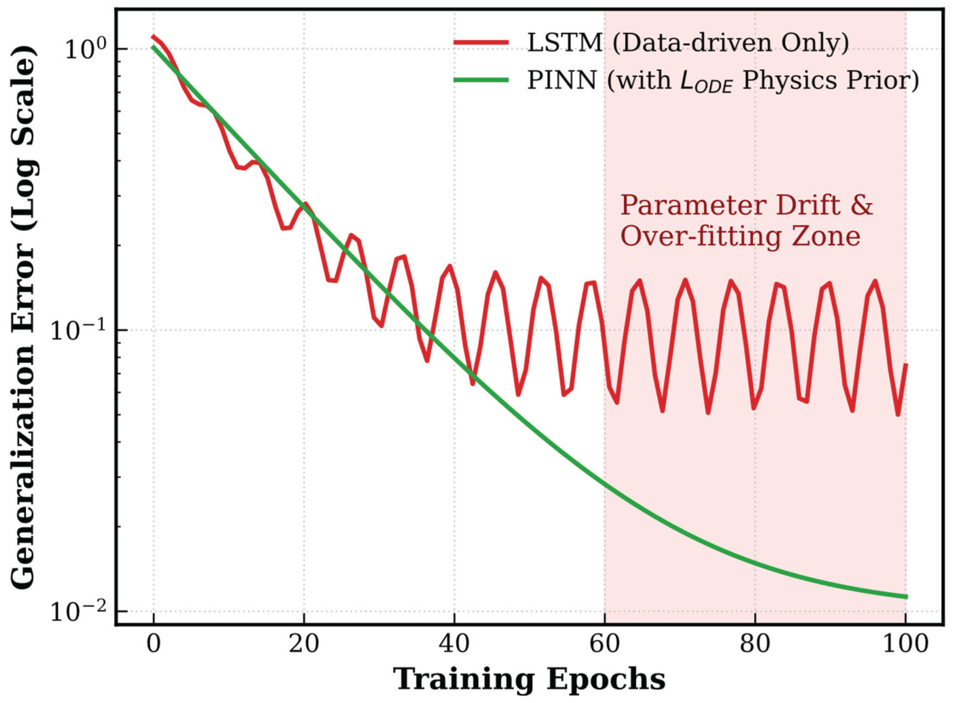
To overcome these limitations, recent studies have explored grey-box architectures, such as PINNs, for ship-dynamics prediction. A key feature of PINNs is that the ODEs governing rigid-body ship motion are embedded directly into the neural-network loss function as physical constraints [75]. The corresponding optimization objective can be written as:
where represents the discrepancy with physical measurements or high-fidelity CFD data, denotes the residual of the 6-DOF rigid-body dynamic equations, and is an adaptive weighting coefficient. By introducing these physical constraints, the solution space is restricted, which can improve generalization even under sparse sampling.
Beyond computational acceleration, the main engineering value of such physics-constrained surrogate models lies in their potential use in operational decision support. As shown in Figure 11, integrating grey-box reduced-order models such as PINNs with real-time meteorological routing data could provide the computational basis for future Digital Twin early-warning systems for WAPS ships. Related studies on adaptive speed control for Flettner-rotor-assisted ships [1,76] suggest that such architectures may support online assessment of aero-hydrodynamic behavior and coordinated multivariable control, thereby improving both navigational safety and decarbonization performance over the ship lifecycle.
9. Conclusions and Future Perspectives
Against the backdrop of maritime decarbonization, large windage structures in WAPS commercial ships have altered the aero-hydrodynamic load distribution and energy dissipation mechanisms of conventional vessels. From a “Hierarchy of Evidence” perspective, this review indicates that no single assessment method can simultaneously satisfy the competing demands of computational efficiency and physical fidelity across the WAPS lifecycle. The main conclusions and future research directions are summarized as follows.
(1) The regulatory transition from quasi-static criteria to DSA is likely to continue. For failure modes that depend strongly on transient waterplane variations, such as parametric rolling, future assessment practice should adopt a stratified strategy, using low-DOF models for preliminary screening and higher-fidelity time-domain simulations for high-risk scenarios.
(2) Traditional steady-state wind-pressure mappings cannot adequately capture aerodynamic hysteresis and dynamic stall in modern WAPS ships under severe oscillatory motion. Future work should further quantify the effects of multi-sail wake interference and use these results to improve the applicability of aerodynamic ROMs, such as the IRM, under strongly nonlinear conditions.
(3) The leeway angle required to balance sail side force can induce asymmetric wakes and cross-flow separation in large-inertia commercial ships. Future maneuvering prediction should therefore move beyond small-leeway linear assumptions by incorporating higher-dimensional hydrodynamic representations into extended 3/4-DOF models.
(4) Models that exclude vertical motions remain limited in wave conditions. More complete coupling between flow-field resolution and 6-DOF rigid-body dynamics, including Coriolis cross-coupling, is important for capturing the combined effects of wave excitation and unsteady wind loads. In this context, full-scale CFD and large-scale basin tests remain essential as calibration and validation references for lower-order models.
(5) Damaged survivability assessment for WAPS ships cannot rely solely on static stability formulations under extreme conditions. Sustained wind heeling in dead-ship conditions, together with internal sloshing after flooding, can significantly modify nonlinear roll damping. Future studies should therefore extend toward time-domain survivability models that couple transient breach-flow effects with internal fluid redistribution.
(6) Long-duration extreme-value extrapolation using 6-DOF architectures remains computationally demanding, while purely data-driven predictions remain vulnerable to parameter drift. Physics-constrained surrogate approaches, particularly PINNs coupled with real-time environmental data, may provide a practical route toward Digital Twin systems for safety monitoring and operational support.
In summary, the dynamic stability assessment of modern wind-assisted commercial ships is shifting from empirical algebraic mapping toward multi-physics time-domain coupling. Improving model fidelity while maintaining computational tractability will remain central to both SGISC-oriented assessment and the future development of intelligent WAPS safety frameworks.:
Acknowledgments
This Work Was Supported by the Natural Science Foundation of Hainan Province, China (625QN392).
Abbreviations
| ABS | American Bureau of Shipping |
| AI | Artificial Intelligence |
| AMSA | Australian Maritime Safety Authority |
| BV | Bureau Veritas |
| CFD | Computational Fluid Dynamics |
| CII | Carbon Intensity Indicator |
| ClassNK | Nippon Kaiji Kyokai |
| DES | Detached Eddy Simulation |
| DNV | Det Norske Veritas |
| DOF | Degree of Freedom |
| DSA | Direct Stability Assessment |
| EEDI | Energy Efficiency Design Index |
| EEXI | Energy Efficiency Existing Ship Index |
| EMSA | European Maritime Safety Agency |
| GHG | Greenhouse Gas |
| IMO | International Maritime Organization |
| IRM | Indicial Response Method |
| IS Code | International Code on Intact Stability |
| KR | Korean Register |
| LES | Large Eddy Simulation |
| LSTM | Long Short-Term Memory |
| MCA | Maritime and Coastguard Agency |
| MIWM | Ministry of Infrastructure and Water Management |
| MMG | Maneuvering Modeling Group |
| ODE | Ordinary Differential Equation |
| PINN | Physics-Informed Neural Network |
| PPP | Performance Prediction Program |
| REG | Red Ensign Group |
| RINA | Registro Italiano Navale |
| ROM | Reduced-Order Model |
| SGISC | Second Generation Intact Stability Criteria |
| URANS | Unsteady Reynolds-Averaged Navier-Stokes |
| USCG | United States Coast Guard |
| VPP | Velocity Prediction Program |
| WAPS | Wind-Assisted Propulsion System |
References
- Wang, K.; Li, Z.; Liu, X.; Hu, Z.; Huang, L.; Song, Q.; Liang, H.; Jiang, X. Wind-Assisted Propulsion System for Shipping Decarbonization: Technologies, Applications and Challenges. Energy 2025, 336, 138420. [CrossRef]
- IMO Adoption of the International Code on Intact Stability, 2008 (2008 IS Code); IMO, 2008;
- Marlantes, K.E.; Kim, S. (Peter); Hurt, L.A. Implementation of the IMO Second Generation Intact Stability Guidelines. JMSE 2021, 10, 41. [CrossRef]
- Sackett, D.L.; Straus, S.E.; Richardson, W.S.; Rosenberg, W.; Haynes, R.B. Evidence-Based Medicine: How to Practice and Teach EBM (Book with CD-ROM); Churchill Livingstone, 2000; ISBN 978-0-443-06240-7.
- Sackett, D.L.; Rosenberg, W.M.C.; Gray, M.; Haynes, B.C.; Richardson, W.S. Evidence Based Medicine: What It Is and What It Isn’t. BMJ (Clin. Res. Ed,) 1996, 312, 71–72. [CrossRef]
- Coleman, H.; Members, C. ASME V&V 20-2009 Standard for Verification and Validation in Computational Fluid Dynamics and Heat Transfer (V&V20 Committee Chair and Principal Author); 2009;
- Chen, S.; Feng, E. Determination of Sail Area in Sail-Assistant Ship. Journal of Wuhan University of Transportation Science and Technology 1995, 420–423.
- Luo, H.; Li, G.; Tan, Z. On the Stability Check of a Boat with Foil Sails. Journal of South China University of Technology (Natural Science Edition) 1986, 36–42.
- ABS Guide for Wind-Assisted Propulsion System Installation; 2020.
- ClassNK Guidelines for Wind-Assisted Propulsion Systems for Ships; 2025.
- DNV DNV-RU-SHIP Pt.6 Ch.2; 2025.
- DNV Wind Assisted Propulsion Systems (DNV-ST-0511); 2025.
- DNV Wind-Assisted Propulsion Systems, White Paper (How WAPS Can Help to Comply with GHG Regulations); DNV AS: Oslo, Norway, 2024;
- DNV DNV-RU-YACHT Pt.3 Ch.10; 2021.
- EMSA Potential of Wind-Assisted Propulsion for Shipping; EMSA: Lisbon, 2023;
- KR Guidelines for Wind-Assisted Propulsion Systems; 2021.
- Lloyd’s Register Guidance Notes on Wind Assisted Propulsion Systems; 2024;
- REG Red Ensign Group Yacht Code; 2024.
- RINA Guidelines for the Certification of Wind Assisted Propulsion Systems; 2020.
- Albers, P.; Vahns, M. The Intact Stability of Wind-Assisted Merchant Vessels. J. Sail. Technol. 2025, 10, 429–461. [CrossRef]
- Deakin, B. The Development of Stability Standards for UK Sailing Vessels. 1990.
- Petacco, N.; Pitardi, D.; Podenzana Bonvino, C.; Gualeni, P. Application of the IMO Second Generation Intact Stability Criteria to a Ballast-Free Containership. JMSE 2021, 9, 1416. [CrossRef]
- Vikström, C. IMO Second Generation Intact Stability Criteria on PCTC’s. 2024, 1–61.
- Bulian, G. Nonlinear Parametric Rolling in Regular Waves—a General Procedure for the Analytical Approximation of the GZ Curve and Its Use in Time Domain Simulations. Ocean Engineering 2005, 32, 309–330. [CrossRef]
- Bulian, G.; Francescutto, A. Second Generation Intact Stability Criteria: On the Validation of Codes for Direct Stability Assessment in the Framework of an Example Application. Pol. Marit. Res. 2013, 20, 52–61. [CrossRef]
- Petacco, N.; Petkovic, G.; Gualeni, P. An Insight on the Post-Processing Procedure of the Direct Stability Assessment within SGISC. Ocean Engineering 2024, 305, 117982. [CrossRef]
- Tillig, F.; Ringsberg, J.W. Design, Operation and Analysis of Wind-Assisted Cargo Ships. Ocean Engineering 2020, 211, 107603. [CrossRef]
- Chen, W.; Wang, H.; Liu, X. Experimental Investigation of the Aerodynamic Performance of Flettner Rotors for Marine Applications. Ocean Engineering 2023, 281, 115006. [CrossRef]
- Seo, J.; Park, D.-W. Numerical Study on the Aerodynamic Performance of Four Flettner Rotors by Varying Distance and Spin Ratio. Journal of Marine Science and Technology 2024, 32. [CrossRef]
- Bouhourd, C.; Perret, L.; Cossu, C. Wingsail Performance in Unsteady Atmospheric Surface Layer Winds. Ocean Engineering 2024, 314, 119653. [CrossRef]
- Zhu, H.; Yao, H.-D.; Thies, F.; Ringsberg, J.W.; Ramne, B. Propulsive Performance of a Rigid Wingsail with Crescent-Shaped Profiles. Ocean Engineering 2023, 285, 115349. [CrossRef]
- Van Reen, S.; Lin, J.; Niu, J.; Sharpe, P.; Li, X.; Yao, H.-D. Reducing Aerodynamic Interference through Layout Optimization of Symmetrically Cambered Wingsails: A Comparative Study of in-Line and Parallel Configurations. JMSE 2025, 13, 1998. [CrossRef]
- Erhard, M.; Strauch, H. Control of Towing Kites for Seagoing Vessels. IEEE Trans. Contr. Syst. Technol. 2013, 21, 1629–1640. [CrossRef]
- Traut, M.; Gilbert, P.; Walsh, C.; Bows, A.; Filippone, A.; Stansby, P.; Wood, R. Propulsive Power Contribution of a Kite and a Flettner Rotor on Selected Shipping Routes. Applied Energy 2014, 113, 362–372. [CrossRef]
- Dhomé, U.; Kuttenkeuler, J.; Segalini, A. Observation of the Atmospheric Boundary Layer over the Atlantic and Its Effects for Wind Propulsion. Journal of Wind Engineering and Industrial Aerodynamics 2025, 258, 106014. [CrossRef]
- Dhomé, U.; Hillenbrand, A.; Kuttenkeuler, J.; Rolleberg, N. Unsteady Pressure Measurements at Sea on the Rigid Wings of a Model Wind Propelled Ship. Part a: Measurement System Development. Ocean Engineering 2025, 331, 121229. [CrossRef]
- Persson, A.; Larsson, L.; Finnsgård, C. A Time-Domain Model for Unsteady Upwind Sail Aerodynamics Using the Indicial Response Method. Ocean Eng. 2024, 299, 117311. [CrossRef]
- Bordogna, G. Aerodynamics of Wind-Assisted Ships: Interaction Effects on the Aerodynamic Performance of Multiple Wind-Propulsion Systems, Delft University of Technology, 2020.
- Ning, X.; Huang, Y.; Wan, D.; Hu, C. Numerical Study of Wake Interaction and Its Effect on Wind Turbine Aerodynamics Based on Actuator Line Model.
- Ding, T.; Tian, C.; Wang, H.; Xu, C.; Ye, J.; Gong, A.; Liu, M.; Xia, T. Performance Enhancement of Autonomous Sailboats via CFD-Optimized Wing–Tail Sail Configurations. J. Mar. Sci. Eng. 2025, 13, 1640. [CrossRef]
- Yasuda, A.; Taniguchi, T.; Katayama, T. Motion Analysis of a Fully Wind-Powered Ship by Using CFD. J. Mar. Sci. Eng. 2026, 14, 121. [CrossRef]
- Kim, D.M.; Hong, S.H.; Jeong, S.H.; Kim, S.J. Analysis of Dynamic Characteristics of Rotor Sail Using a 4DOF Rotor Model and Finite Element Model. JMSE 2024, 12, 335. [CrossRef]
- Leloup, R.; Roncin, K.; Behrel, M.; Bles, G.; Leroux, J.-B.; Jochum, C.; Parlier, Y. A Continuous and Analytical Modeling for Kites as Auxiliary Propulsion Devoted to Merchant Ships, Including Fuel Saving Estimation. Renewable Energy 2016, 86, 483–496. [CrossRef]
- Reche-Vilanova, M.; Hansen, H.; Bingham, H.B. Performance Prediction Program for Wind-Assisted Cargo Ships. J. Sail. Technol. 2021, 6, 91–117. [CrossRef]
- Chatterton, H.A.; Maxham, J.C. Sailing Vessel Stabilitymwith Particular Reference to the Pride of Baltimore Casualty. 1989, 1–18.
- Cirello, A.; Mancuso, A. A Numerical Approach to the Keel Design of a Sailing Yacht. Ocean Engineering 2008, 35, 1439–1447. [CrossRef]
- Hu, J.; Lin, S.; Chen, Q.; Zhu, Z. Research for the Influences of Load Position on Large Angle Stability of Keel Boat. J. Jimei Univ.(Nat. Sci.) 2016, 21, 130–135. [CrossRef]
- Wang, H. Study on Nonlinear Roll Motion and Sailing Safety of Wing-Assisted Ships, Dalian Maritime University: Dalian, 2013.
- Plessas, T.; Papanikolaou, A. Design Optimization and Assessment Platform for Wind-Assisted Ship Propulsion. J. Mar. Sci. Eng. 2025, 13, 1389. [CrossRef]
- Plessas, T.; Papanikolaou, A. Multi-Objective Optimization of Ship Design for the Effect of Wind Propulsion. J. Mar. Sci. Eng. 2025, 13, 167. [CrossRef]
- Viola, I.M.; Bartesaghi, S.; Van-Renterghem, T.; Ponzini, R. Detached Eddy Simulation of a Sailing Yacht. Ocean Engineering 2014, 90, 93–103. [CrossRef]
- Huetz, L.; Alessandrini, B. Systematic Study of the Hydrodynamic Forces on a Sailing Yacht Hull Using Parametric Design and CFD. In Proceedings of the Volume 6: Ocean Engineering; American Society of Mechanical Engineers Digital Collection, January 1 2011; pp. 889–898.
- Hosseinzadeh, S.; Hudson, D.; R. Turnock, S.; Prince, M.; Banks, J. Influence of Hull–Propeller–Rudder Interaction on the Self-Propulsion of Wind-Assisted Ships. Phys. Fluids 2025, 37, 087216. [CrossRef]
- Viola, I.M.; Sacher, M.; Xu, J.; Wang, F. A Numerical Method for the Design of Ships with Wind-Assisted Propulsion. Ocean Engineering 2015, 105, 33–42. [CrossRef]
- Zhou, S.; Chen, W. Influence of Sails on Ship Maneuverability Based on Numerical Simulation. Sh. Boat 2025, 36, 15. [CrossRef]
- Vinje Kramer, J.; Steen, S. Sail-Induced Resistance on a Wind-Powered Cargo Ship. Ocean Eng. 2022, 261, 111688. [CrossRef]
- Neves, M.; Rodríguez, C. A Non-Linear Mathematical Model of Higher Order for Strong Parametric Resonance of the Roll Motion of Ships in Waves. Mar. Syst. Ocean Technol. 2005, 1, 69–81. [CrossRef]
- Levin, R.L.; Larsson, L. Sailing Yacht Performance Prediction Based on Coupled CFD and Rigid Body Dynamics in 6 Degrees of Freedom. Ocean Eng. 2017, 144, 362–373. [CrossRef]
- Angelou, M.; Spyrou, K.J. Dynamic Stability Assessment of Yacht Downwind Sailing in Regular Waves. Applied Ocean Research 2021, 111, 102651. [CrossRef]
- Angelou, M.; Spyrou, K.J. Modeling of Transient Hydrodynamic Lifting Forces of Sailing Yachts and Study of Their Effect on Maneuvering in Waves. Ocean Engineering 2019, 173, 531–547. [CrossRef]
- Angelou, M.; Spyrou, K.J. A New Mathematical Model for Investigating Course Stability and Maneuvering Motions of Sailing Yachts. J. Sail. Technol. 2017, 2, 1–42. [CrossRef]
- Gualeni, P.; Paolobello, D.; Petacco, N.; Lena, C. Seakeeping Time Domain Simulations for Surf-Riding/Broaching: Investigations toward a Direct Stability Assessment. J. Mar. Sci. Technol. 2020, 25, 1120–1128. [CrossRef]
- Charlou, M.; Babarit, A.; Gentaz, L. A New Validated Open-Source Numerical Tool for the Evaluation of the Performance of Wind-Assisted Ship Propulsion Systems. Mechanics & Industry 2023, 24, 26. [CrossRef]
- Persson, A. Predicting Yacht Performance in Waves Using a CFD Velocity Prediction Program. 2025.
- Kjellberg, M.; Gerhardt, F.; Werner, S. Sailing Performance of Wind-Powered Cargo Vessel in Unsteady Conditions. J. Sail. Technol. 2023, 8, 218–254. [CrossRef]
- Taghipour, R.; Perez, T.; Moan, T. Hybrid Frequency–Time Domain Models for Dynamic Response Analysis of Marine Structures. Ocean Engineering 2008, 35, 685–705. [CrossRef]
- Liu, L.; Chen, M.; Wang, X.; Zhang, Z.; Yu, J.; Feng, D. CFD Prediction of Full-Scale Ship Parametric Roll in Head Wave. Ocean Engineering 2021, 233, 109180. [CrossRef]
- Belenky, V.; Weems, K.; Lin, W.-M. Split-Time Method for Estimation of Probability of Capsizing Caused by Pure Loss of Stability. Ocean Engineering 2016, 122, 333–343. [CrossRef]
- Shin, D.M.; Chung, J. Application of Dead Ship Condition Based on IMO Second-Generation Intact Stability Criteria for 13K Oil Chemical Tanker. Ocean Engineering 2021, 238, 109776. [CrossRef]
- Shin, D.-M.; Moon, B.-Y. Assessment of Excessive Acceleration of the IMO Second Generation Intact Stability Criteria for the Tanker. JMSE 2022, 10, 229. [CrossRef]
- Ruponen, P.; Van Basten Batenburg, R.; Van’T Veer, R.; Braidotti, L.; Bu, S.; Dankowski, H.; Lee, G.J.; Mauro, F.; Ruth, E.; Tompuri, M. International Benchmark Study on Numerical Simulation of Flooding and Motions of a Damaged Cruise Ship. Appl. Ocean Res. 2022, 129, 103403. [CrossRef]
- Zhang, X.; Li, Z.; Mancini, S.; Qu, Q.; Zhu, R. Experimental Investigation into the Roll Damping Characteristics of the Intact and Damaged Ship in Still Water and Ice Floes. Applied Ocean Research 2026, 168, 104975. [CrossRef]
- Silva, K.M.; Maki, K.J. Data-Driven System Identification of 6-DoF Ship Motion in Waves with Neural Networks. Applied Ocean Research 2022, 125, 103222. [CrossRef]
- Yue, J.; Liu, L.; Gu, N.; Peng, Z.; Wang, D.; Dong, Y. Online Adaptive Parameter Identification of an Unmanned Surface Vehicle without Persistency of Excitation. Ocean Eng. 2022, 250, 110232. [CrossRef]
- An, G.; Xiang, G.; Xiang, X.; Guedes Soares, C. Physics Informed Neural Networks Based Identification Modelling of Ship Maneuvering Motion and Associated Optimal Excitation Design. Engineering Applications of Computational Fluid Mechanics 2025, 19, 2566860. [CrossRef]
- Jang, S.; Chae, H.; Roh, C. Comparison of Fixed and Adaptive Speed Control for a Flettner-Rotor-Assisted Coastal Ship Using Coupled Maneuvering-Energy Simulation. J. Mar. Sci. Eng. 2026, 14, 210. [CrossRef]
Figure 2.
Funnel-type” evolutionary architecture of evidence stratification for dynamic stability assessment of modern wind-assisted commercial ships.
Figure 2.
Funnel-type” evolutionary architecture of evidence stratification for dynamic stability assessment of modern wind-assisted commercial ships.
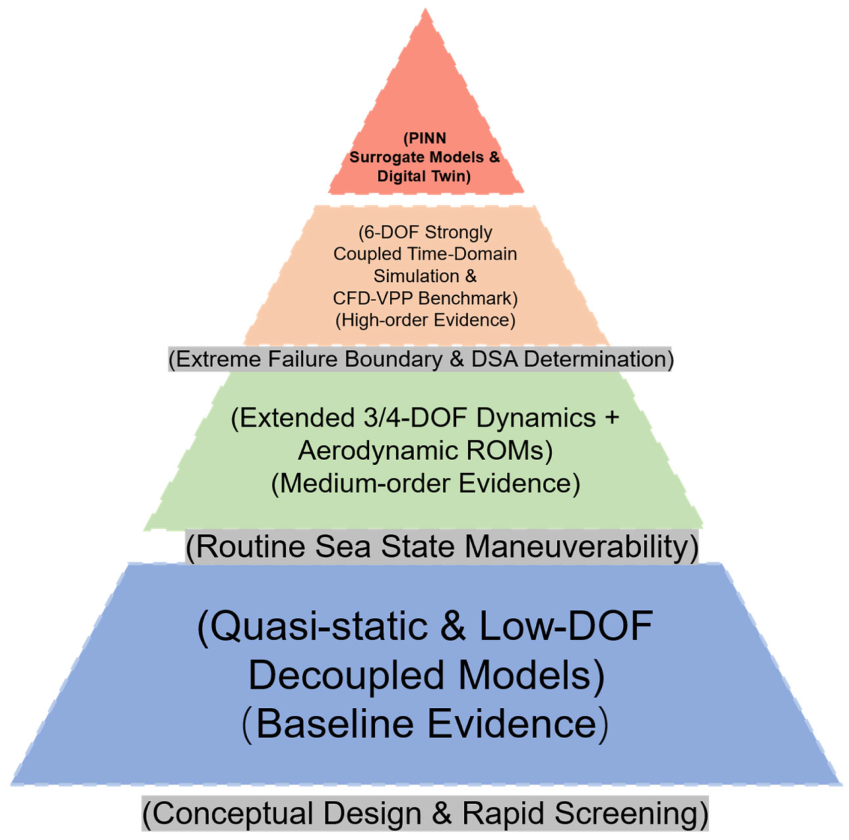
Figure 3.
Historical methodological evolution and multi-physics time-domain coupling roadmap for stability assessment of wind-assisted commercial ships.
Figure 3.
Historical methodological evolution and multi-physics time-domain coupling roadmap for stability assessment of wind-assisted commercial ships.
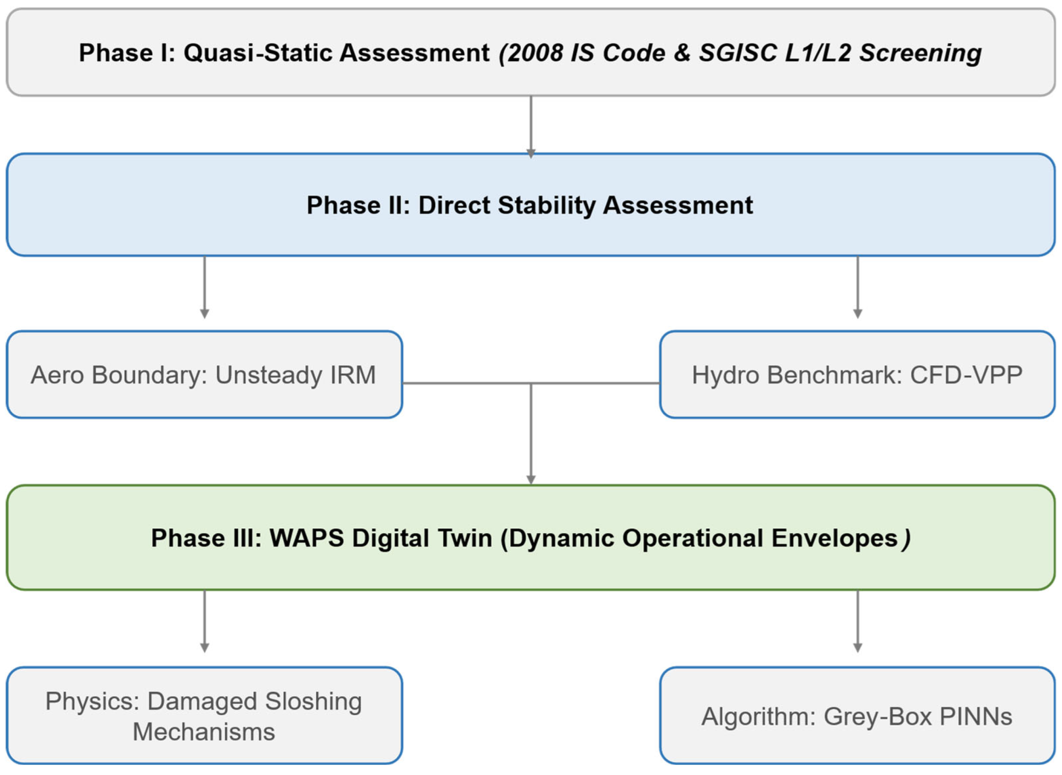
Figure 4.
Comparison of physical characteristics between the quasi-static assumption and unsteady aerodynamic hysteresis loop under extreme gust excitation (Adapted from [37]).
Figure 4.
Comparison of physical characteristics between the quasi-static assumption and unsteady aerodynamic hysteresis loop under extreme gust excitation (Adapted from [37]).
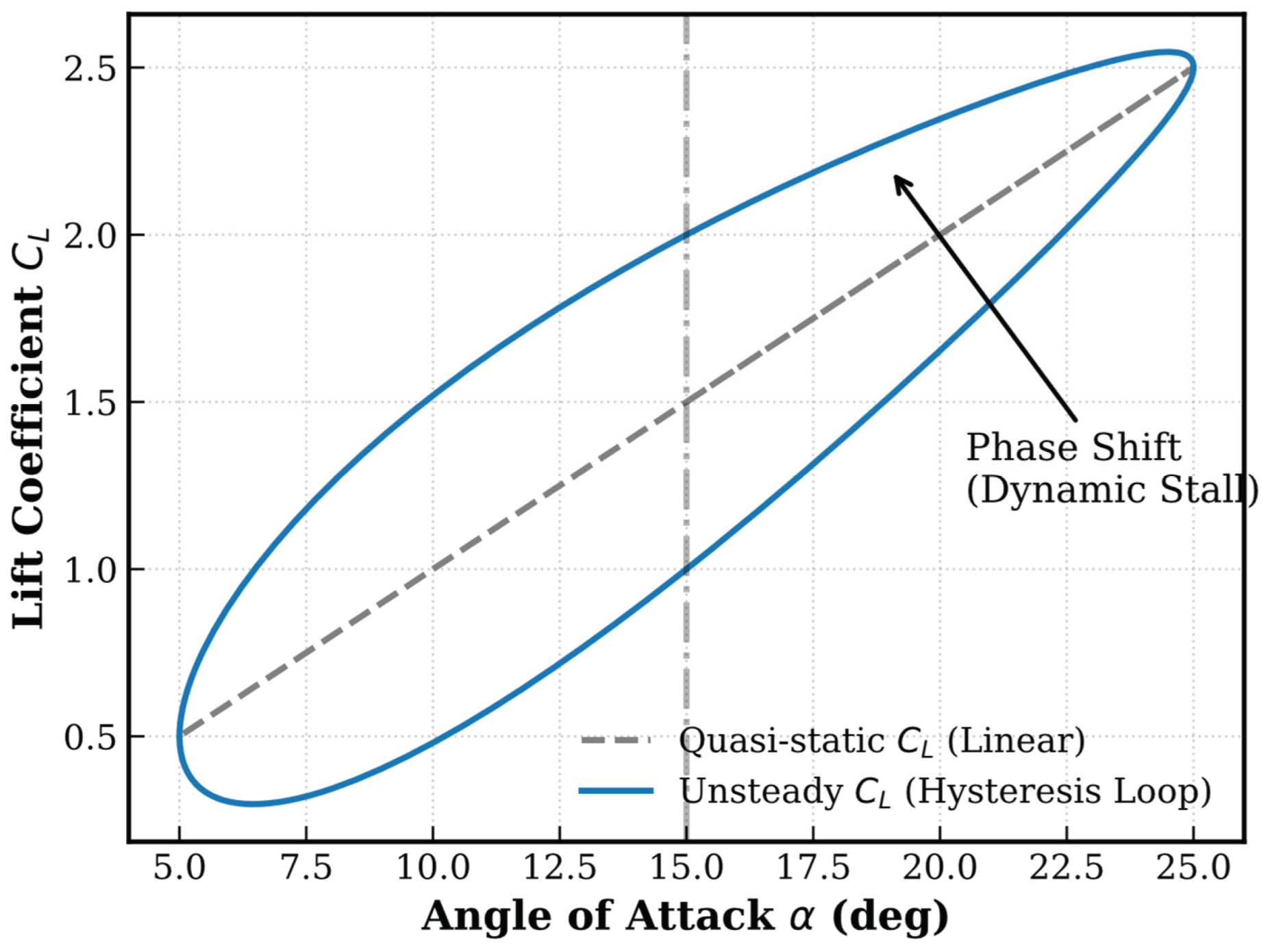
Figure 5.
Asymmetric force balance and hull-rudder wake interference mechanism of WAPS commercial ships under leeway angle.
Figure 5.
Asymmetric force balance and hull-rudder wake interference mechanism of WAPS commercial ships under leeway angle.
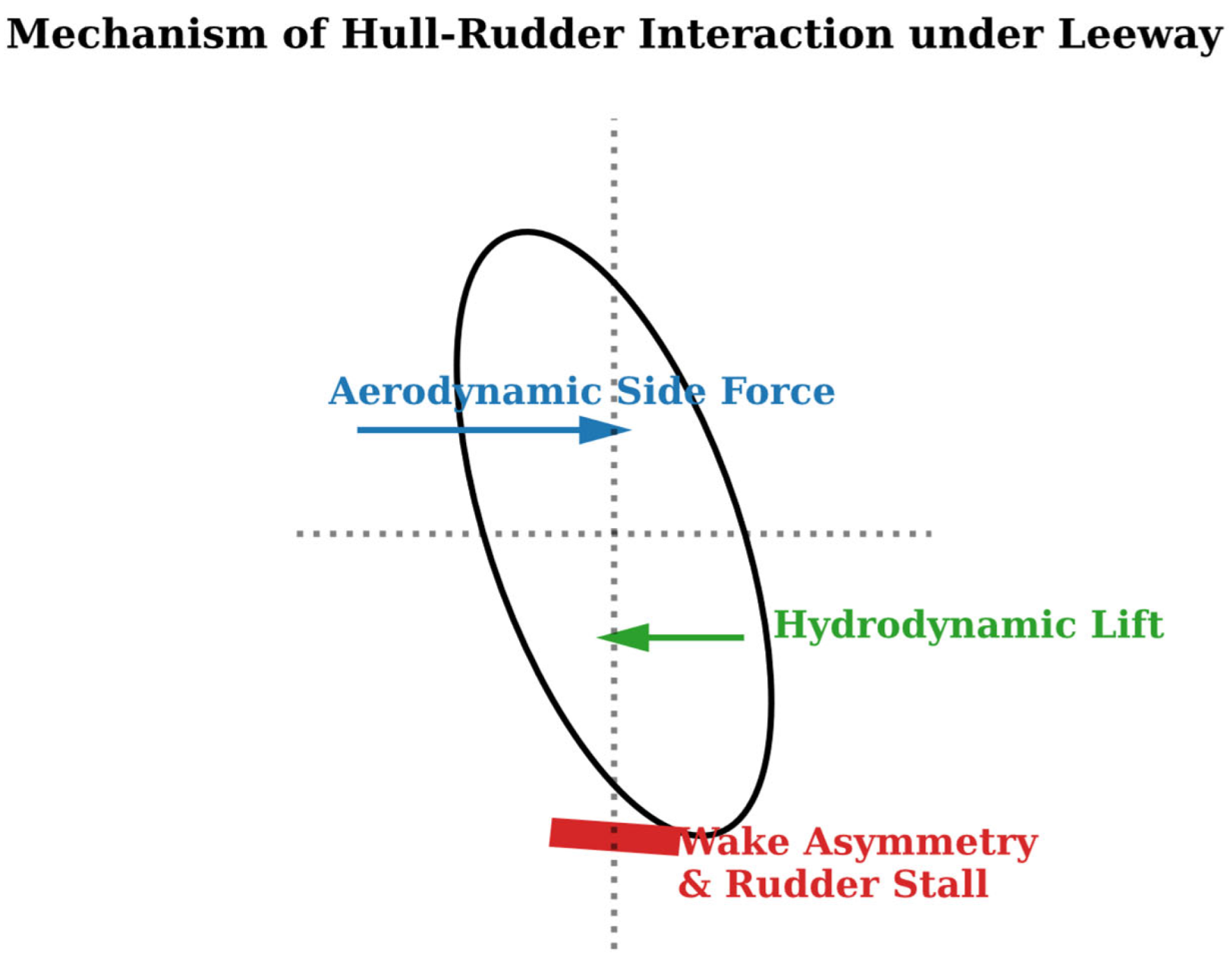
Figure 6.
Non-linear evolution of ship hydrodynamic resistance induced by increasing leeway angle and its divergence from linear assumption (Conceptual trend adapted from the physical descriptions in [52]).
Figure 6.
Non-linear evolution of ship hydrodynamic resistance induced by increasing leeway angle and its divergence from linear assumption (Conceptual trend adapted from the physical descriptions in [52]).
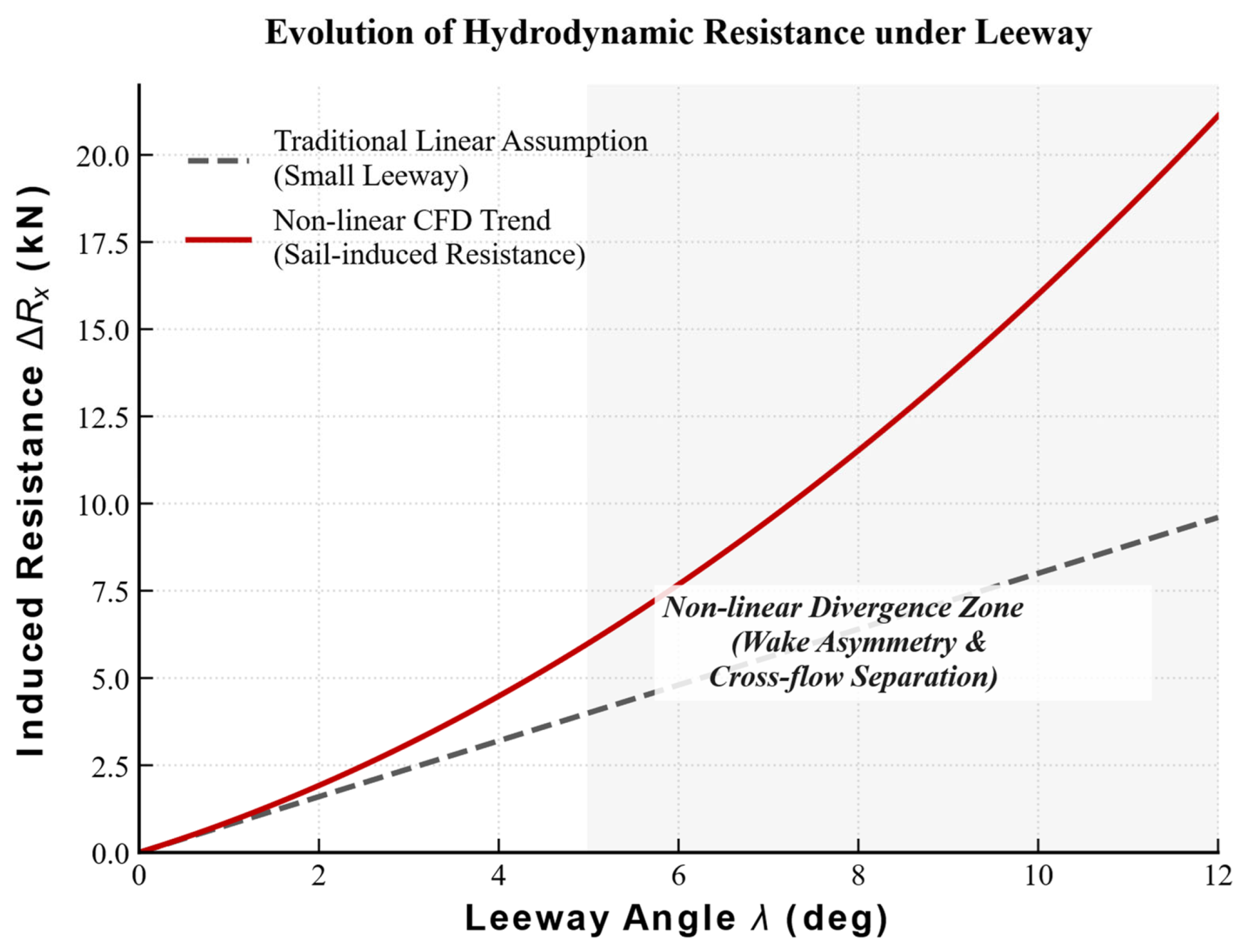
Figure 7.
Comparison of surf-riding and broaching-to transient histories between 6-DOF time-domain simulations and physical measurements (Physical evolution trend adapted from [61]).
Figure 7.
Comparison of surf-riding and broaching-to transient histories between 6-DOF time-domain simulations and physical measurements (Physical evolution trend adapted from [61]).
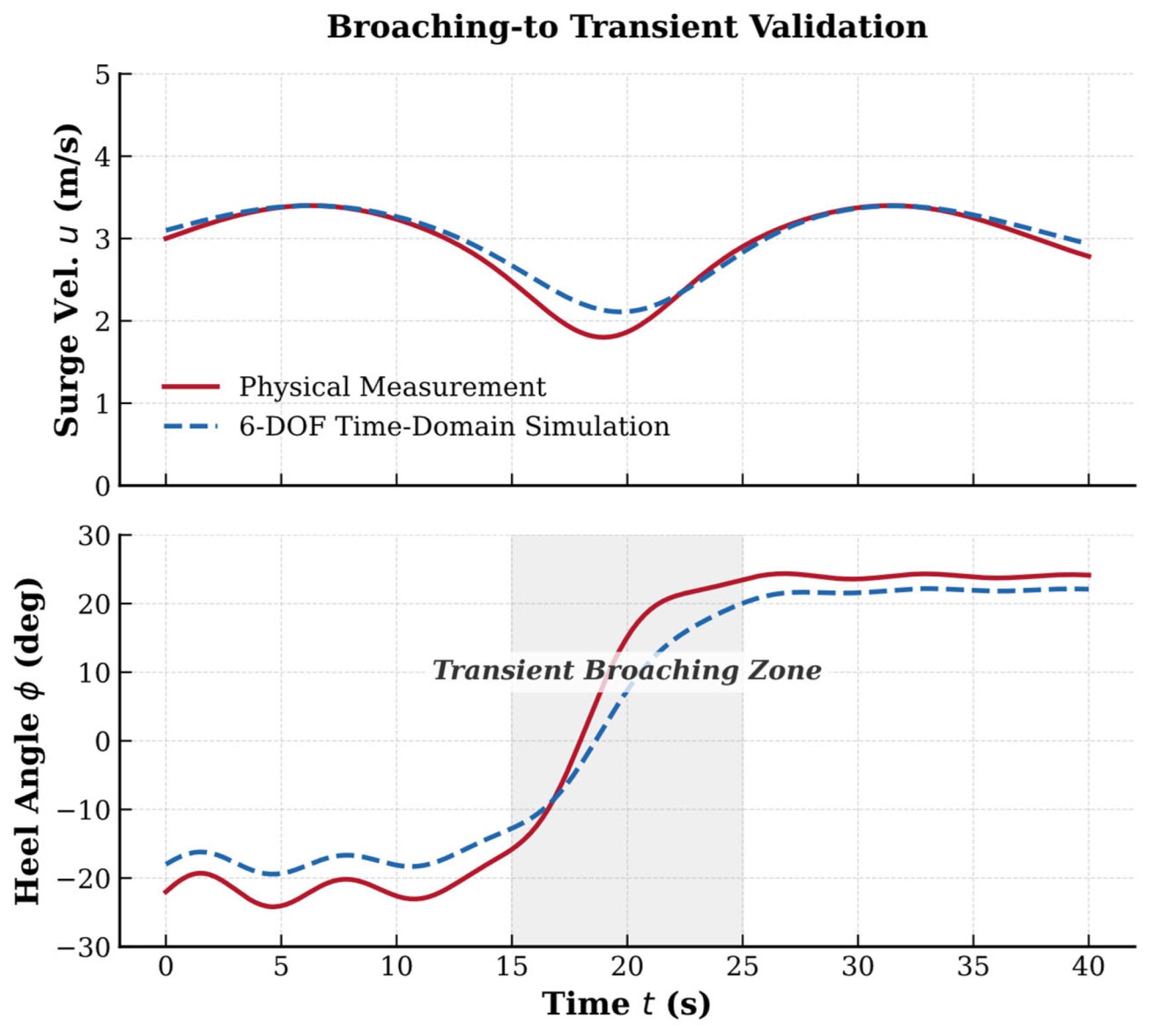
Figure 8.
Conceptual phase plane trajectory of non-linear roll for WAPS ships with aerodynamic bias under extreme wind and wave excitation (Conceptualized and redrawn based on the topological features from [48]).
Figure 8.
Conceptual phase plane trajectory of non-linear roll for WAPS ships with aerodynamic bias under extreme wind and wave excitation (Conceptualized and redrawn based on the topological features from [48]).
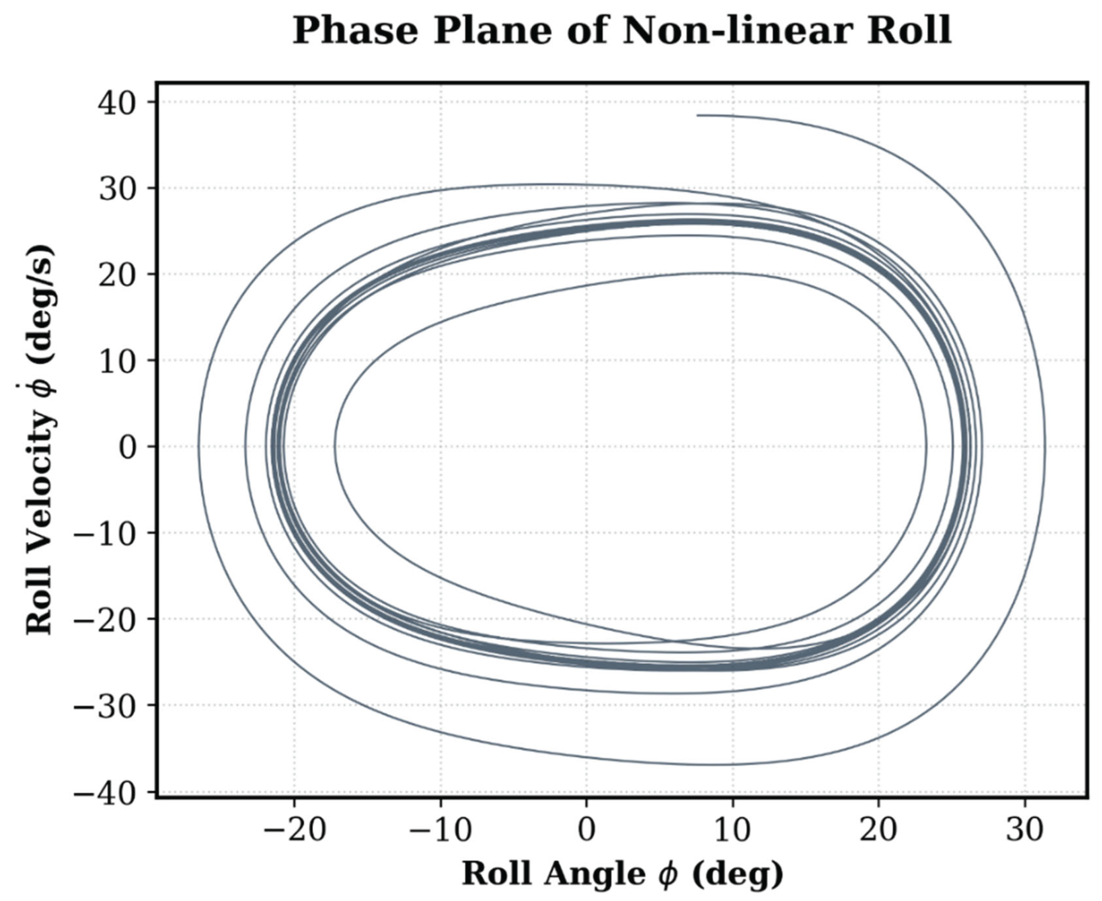
Figure 9.
Comparison of roll-decay behavior in intact and damaged conditions, illustrating damping distortion induced by sloshing in damaged compartments (conceptualized from [72]).
Figure 9.
Comparison of roll-decay behavior in intact and damaged conditions, illustrating damping distortion induced by sloshing in damaged compartments (conceptualized from [72]).
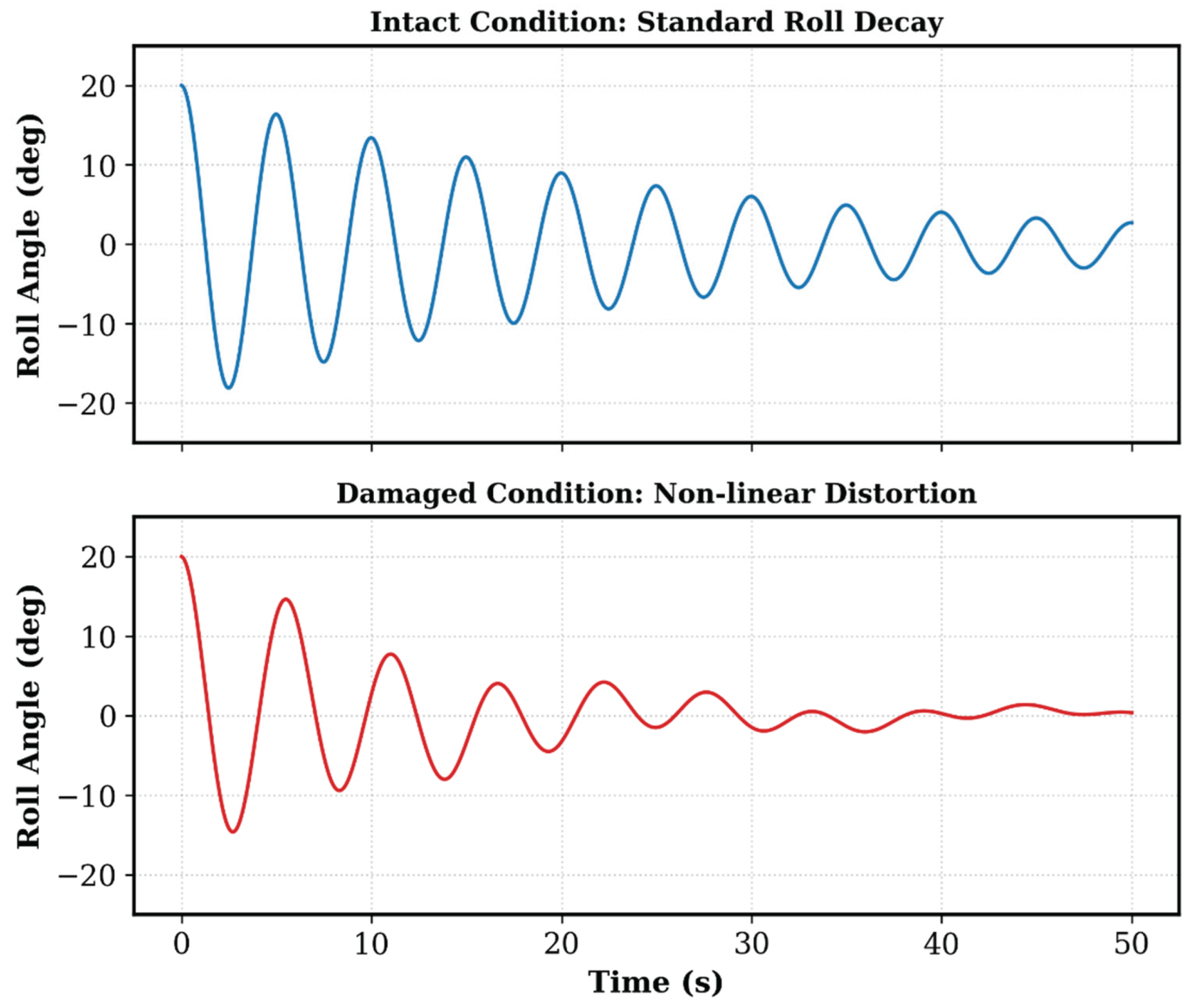
Figure 11.
Overall architecture of the digital twin for WAPS commercial ships, integrating aerodynamic/hydrodynamic solvers, AI surrogate models, and adaptive control (Adapted from [1]).
Figure 11.
Overall architecture of the digital twin for WAPS commercial ships, integrating aerodynamic/hydrodynamic solvers, AI surrogate models, and adaptive control (Adapted from [1]).
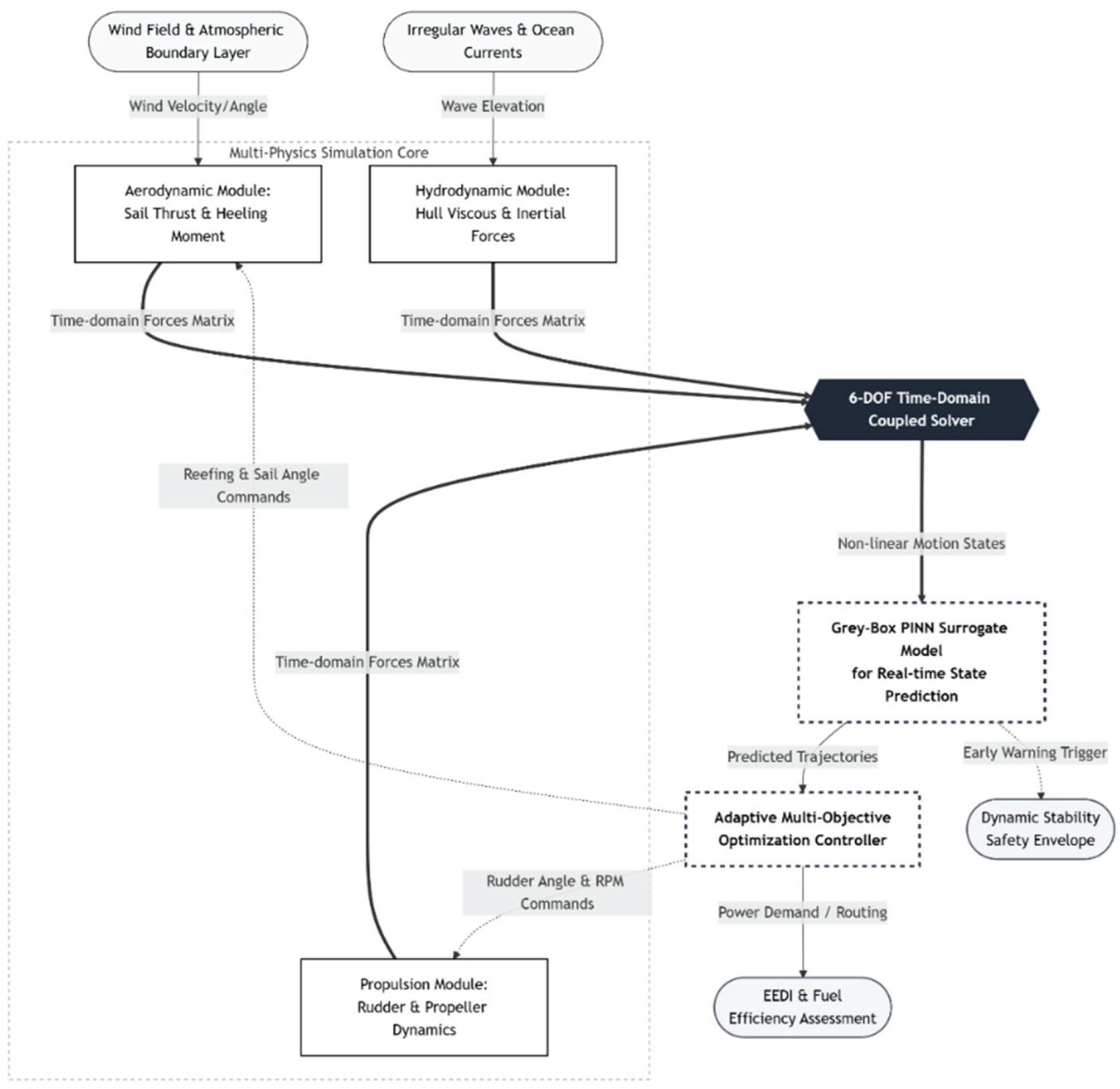

Table 1.
Horizontal comparison of current stability assessment frameworks and their applicability to WAPS.
Table 1.
Horizontal comparison of current stability assessment frameworks and their applicability to WAPS.
| Standard/Assessment framework | Core processing logic | Wind load & gust input model | Fluid-structure interaction & damping considerations | Applicable scenarios & assessment positioning for WAPS |
| 2008 IS Code (Weather criterion) | Area energy balance under calm water righting lever curve | Mean wind pressure + empirical gust factor | Uses empirical roll damping coefficients; no explicit calculation of dynamic damping | Suitable for early design approval of conventional low-windage commercial ships; oversimplified for large-area WAPS. |
| WAPS-specific guidelines by classification societies | Static correction and expansion based on IS Code | Wind speed height profile conversion + steady aerodynamic derivatives | Partially allows steady aerodynamic damping corrections | Suitable for preliminary WAPS selection and rapid compliance verification; highly conservative. |
| SGISC (L1/L2 screening) | Semi-empirical/analytical screening for five dynamic failure modes | Simplified frequency-domain response or quasi-steady wind pressure | Introduces simplified hydrodynamic damping model in parametric rolling | Suitable for early screening of dynamic instability; large-area WAPS configurations are difficult to pass, easily triggering DSA. |
| SGISC DSA (Direct Stability Assessment) | Long-duration extreme value extrapolation under combined wave and wind excitation | Time-domain unsteady aerodynamic forces + irregular wave sequences | Explicitly requires solving nonlinear time-domain motion equations | Suitable for final decision-making and operational guidance in high-risk dynamic conditions; strictly requires code validation and post-processing. |
Table 2.
Horizontal comparison of hydrodynamic modeling tiers for WAPS ships.
| Modeling tier | DOF & Core physics | Fidelity / Cost | Large leeway & interference | Evidence & Applicability |
| Low-leeway empirical | Decoupled (calm water) | Low / V. Low | No / No | Weak ᵃ |
| Extended MMG | 3/4-DOF | Medium / Low | Partial / Partial | Strong ᵇ |
| 6-DOF hybrid | 6-DOF (+ waves/Coriolis) | High / High | Yes / Yes | Moderate ᶜ |
| 6-DOF CFD-VPP | Full N-S equations | V. High / V. High | Yes / Yes | Strong ᵈ |
Note: V Low/V High=Very Low/Very High. N-S=Navier-Stokes. Footnotes: ᵃ Mostly extrapolated from empirical formulas for conventional ships or yachts; suitable only for rapid screening in early conceptual design. ᵇ Mature models exist for commercial WAPS ships; most suitable for maneuverability prediction and routing energy efficiency optimization. ᶜ Capable of covering SGISC dynamic failure modes, but systematic large-scale basin calibration data for full-scale commercial WAPS is currently limited. ᵈ Captures nonlinear characteristics of sail-induced resistance; serves as a cross-validation benchmark for the WAPS PPP toolchain.
Table 3.
Comparison table of stability assessment methods.
| Stability assessment method | Computational accuracy | Scope of application | Computational complexity | Computational efficiency | Applicable ship types |
| SGISC | Medium | General | Low | High | Conventional ships |
| 6-DOF | High | Broad | High | Low | WAPS, etc. |
| CFD-VPP | High | Specific conditions | Very high | Very low | WAPS, etc. |
| PINN | High | Extreme conditions | High | Low | All types |
Table 4.
Matrix of dynamic instability modes, WAPS modeling requirements, and evidence strength.
| Dynamic failure mode | Core physical mechanism & conventional influencing factors | New or amplified factors introduced by WAPS | Applicability boundaries & evidence strength in WAPS scenarios |
| Parametric rolling | Parametric resonance induced by periodic variations in restoring lever | Aerodynamic phase hysteresis interference, asymmetric distortion caused by fixed heel | Strong: Energy theory for conventional ships is mature; analogous prediction cases based on non-traditional hull forms exist. |
| Pure loss of stability / Dead ship condition | Sharp decrease in stability due to prolonged wave crest residence / Beam sea resonance under loss of power | Strong superimposition of sustained aerodynamic heeling moment from sail array and wave excitation under dead ship condition | Moderate: Application cases for conventional oil/chemical tankers exist; physical basin data for extreme capsizing of large-area sails remains relatively limited. |
| Surf-riding / Broaching-to | Loss of heading control induced by wave orbital velocity leading to yawing | Aerodynamic yawing moment may dominate when rudder effectiveness is transiently lost due to surf-riding | Weak: Conventional time-domain simulation theory is mature; the quantitative evolution mechanism of broaching-to after introducing aerodynamic matrices is still under exploration. |
| Excessive acceleration | Lateral inertial force generated by ship rolling at a high position | Towering mast structure of WAPS amplifies roll radius and high-position forces | Moderate: Evaluation for high-center-of-gravity ship types is mature; force validation for the base of large wingsails in random waves needs to be enriched. |
Disclaimer/Publisher’s Note: The statements, opinions and data contained in all publications are solely those of the individual author(s) and contributor(s) and not of MDPI and/or the editor(s). MDPI and/or the editor(s) disclaim responsibility for any injury to people or property resulting from any ideas, methods, instructions or products referred to in the content. |
© 2026 by the authors. Licensee MDPI, Basel, Switzerland. This article is an open access article distributed under the terms and conditions of the Creative Commons Attribution (CC BY) license (http://creativecommons.org/licenses/by/4.0/).
Copyright: This open access article is published under a Creative Commons CC BY 4.0 license, which permit the free download, distribution, and reuse, provided that the author and preprint are cited in any reuse.


