

Submitted:
16 May 2026
Posted:
19 May 2026
You are already at the latest version
Abstract
This paper presents the Micro Video Guidance Sensor (UVGS-2), an advanced evolution of the Smartphone Video Guidance Sensor (SVGS), a vision-based 6-DOF pose estimation system for proximity operations in spacecraft, UAVs, and mobile robot platforms. The system is based on the photogrammetric estimation of a beacon’s relative position and attitude in a camera coordinate system, by processing images of illuminated 4-points in the beacon with known non-coplanar geometry. Estimation of the beacon’s 6-DOF position and attitude (XYZ, RPY) in a coordinate system attached to the camera is achieved with higher accuracy compared to standard localization methods based on mapping or inertial navigation. Image acquisition, feature extraction, and state estimation are executed using hardware resources (camera and CPU) of the host robot, resulting in a low-mass, low-power, computationally efficient sensing architecture suitable for embedded and resource-constrained systems. As case study, SVGS and UVGS-2 have been deployed as real-time guidance, navigation, and motion control sensor through integration with NASA’s Astrobee free-flying robot aboard the International Space Station (ISS), supporting autonomous proximity operations and formation flight. Sensor fusion based on the use of existing localization pipelines improves robustness against line-of-sight interruptions and illumination disturbances, and improves accuracy compared to the native Astrobee localization system (AstroLoc). Other case studies have demonstrated high-precision positioning performance in autonomous UAV landing experiments, with reliable target tracking over extended ranges and low angular estimation error, outperforming existing infrared-based landing approaches.
Keywords:
vision-based 6-DoF pose estimation
; autonomous proximity operations
; photogrammetric state estimation
; localization
; navigation in GPS-denied environment
1. Introduction
The Smartphone Video Guidance Sensor (SVGS) is a vision-based relative navigation system designed to estimate the six-degrees-of-freedom (6-DOF) pose of a target with respect to a camera-centric reference frame. It operates by photogrammetric principles applied to monocular imagery, enabling the reconstruction of both translational and rotational states from two-dimensional image streams. Unlike standard navigation sensors that rely on active ranging (such as LiDAR or radar) SVGS employs passive or semi-active illumination, detecting either retroreflective markers or actively illuminated points arranged in a known geometric configuration [1]. This architecture allows SVGS to function as a lightweight, low-power, cost-effective alternative for proximity operations in constrained platforms such as CubeSats – Spacecrafts [2], unmanned aerial vehicles [3], and mobile robots. SVGS computes the relative pose by capturing images of a target pattern composed of multiple fiducial points with known spatial relationships [4,5]. The points, projected onto the image plane, form a set of features (blobs) whose pixel coordinates encode geometric information about the relative position and orientation of the target [6]. The system uses photogrammetric reconstruction, in particular from the collinearity equations, to invert the perspective projection and recover the 3D state vector [7], which comprises the relative translation (X, Y, Z) and orientation angles (roll, pitch, yaw) of the target relative to the camera frame, leading to a 6×1 state representation suitable for integration into guidance, navigation, and control (GNC) architectures [8].
SVGS uses a monocular imaging system [9], such as smartphone camera [10], following a thin-lens model: rays from each target point converge at the camera’s perspective center and are projected onto the image plane. By establishing a map between object-space coordinates and image-space measurements, SVGS formulates a nonlinear estimation problem, solved iteratively by linearization techniques (e.g. first-order Taylor expansion), correcting an initial state estimate through least-squares minimization of reprojection errors. The iterative refinement continues until convergence criteria are met, yielding a high-fidelity estimate of the relative pose. The geometric configuration of the target plays a critical role in the accuracy of the SVGS solution [4]. Typically, the system employs a non-coplanar array of at least four fiducial markers, where three are positioned on a plane and a fourth is offset on a perpendicular axis. The out-of-plane feature enhances the conditioning of the attitude estimation problem, reducing ambiguity in rotational states. The transformation between camera frame and target frame consists of a rotation matrix and translation vector, which constitute the estimated target pose.
The SVGS algorithm includes image acquisition, blob extraction, target identification, and state estimation. The image is first thresholded to isolate bright regions corresponding to the target markers, after which blob detection techniques are applied to determine their centroids and morphological properties. SVGS uses geometric consistency checks to associate detected blobs with the known target pattern. Once correspondence is established, the centroid coordinates are used as inputs to the photogrammetric solver, which computes the relative pose as a constrained optimization. In SVGS, all computations—from image capture to state estimation—are performed at the sensing device, reducing latency from data transmission and alleviating computational burdens on the flight computer. The SVGS 6-DOF state estimate can be directly interfaced with higher-level control algorithms such as Kalman filters and model-based controllers, to enable autonomous navigation and relative maneuvers. SVGS thus represents a scalable and versatile solution for proximity operations in resource-constrained platforms [1].
The SVGS mission APK is a Java for Android application that includes the logic and sequence of function calls from both the Astrobee API and Guest Science Library, in support of the functionality required to implement the guest science maneuvers and collect data as described above. The software integration flow chart is shown in Figure 3 and Figure 4, the SVGS service sends status and pose 6-DOF vectors to GDS through the GDS result string. To avoid overflow, it can be limited to occur at a lower frequency.
1.1. The SVGS-1 Mission on the International Space Station
The mission was conceived as a technology demonstration to evaluate performance, robustness, and operational feasibility of SVGS when deployed in a representative space environment, with ISS as a testbed for proximity operations and formation flight [11]. Central to the experiment was the demonstration of SVGS as a software sensor that can be deployed using hardware resources (camera and CPU) of a host robot platform such as NASA’s Astrobee, using illuminated beacons as shown in Figure 1 and Figure 2 [12]. The experimental campaign was a sequence of increasingly complex maneuvers designed to emulate proximity operations such as rendezvous, station-keeping, and formation flight, enabling performance characterization under dynamic conditions.
In Maneuver 1 (fixed-target maneuver), a single SVGS beacon is mounted on the ISS wall, defining a stationary reference frame against which the relative pose of the free-flying robot is continuously estimated. The maneuver outline is illustrated in Figure 5 (left), while the actual experimental configuration is shown in Figure 5 (right).
Figure 3.
SVGS integration with Astrobee’s Guest Science Library and Application Programming Interface (API), illustrating the interaction between the Guest Science application layer and core flight software. Data flow from the image acquisition and vision-processing pipeline ends on generation of relative pose estimates. SVGS is initialized, executed, and monitored through service calls, conditional execution flags, and telemetry streaming. Synchronization constraints between asynchronous image processing and the deterministic control loop illustrates timing, thread management, and state validation. Pose data is transmitted to both onboard control modules and the Ground Data System (GDS).
Figure 3.
SVGS integration with Astrobee’s Guest Science Library and Application Programming Interface (API), illustrating the interaction between the Guest Science application layer and core flight software. Data flow from the image acquisition and vision-processing pipeline ends on generation of relative pose estimates. SVGS is initialized, executed, and monitored through service calls, conditional execution flags, and telemetry streaming. Synchronization constraints between asynchronous image processing and the deterministic control loop illustrates timing, thread management, and state validation. Pose data is transmitted to both onboard control modules and the Ground Data System (GDS).
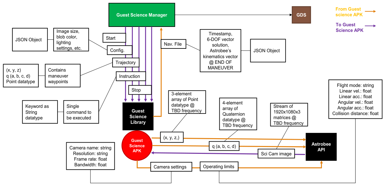
Figure 4.
SVGS mission Android Package (APK) architecture, illustrating control interfacing and experiment management components. The perception module (SVGS block, right) encapsulates the vision pipeline, while the control interface (center block) manages communication with Astrobee’s GNC subsystem. The telemetry module (left block) supports data logging and transmission to the Ground Data System, incorporating rate-limiting to comply with bandwidth constraints.
Figure 4.
SVGS mission Android Package (APK) architecture, illustrating control interfacing and experiment management components. The perception module (SVGS block, right) encapsulates the vision pipeline, while the control interface (center block) manages communication with Astrobee’s GNC subsystem. The telemetry module (left block) supports data logging and transmission to the Ground Data System, incorporating rate-limiting to comply with bandwidth constraints.
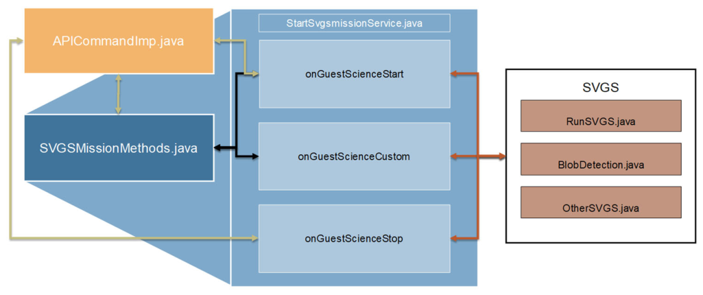
Figure 5.
SVGS Maneuver 1: axial translations, controlled approach and rotational perturbations in roll, pitch, and yaw.
Figure 5.
SVGS Maneuver 1: axial translations, controlled approach and rotational perturbations in roll, pitch, and yaw.
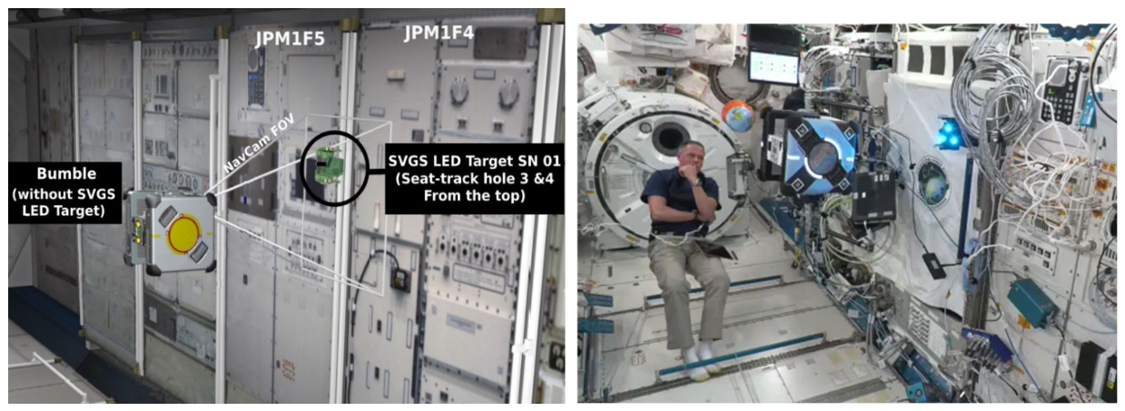
Maneuver 1 (Figure 5) consists of a sequence of translation and rotation motions from an initial standoff distance of approximately 1 m from the ISS panel. The robot performs controlled approach and retreat motions along the camera axis, followed by a sequence of rotations in roll, pitch, and yaw of approximately ±30 degrees.
In Maneuver 2 (Figure 6), the “Leader” Astrobee performs a prescribed 6DOF trajectory with respect to a wall-mounted target. The “Follower” Astrobee follows the leader in a parallel plane, at a fixed distance. This imposes stricter requirements on estimation and synchronization, as errors in the leader’s motion propagate into the follower’s control [13]. Maneuver 2 was divided into 2A (Leader square maneuver using Astrobee metrology and SVGS), 2C (Leader square maneuver using only Astrobee metrology) and 2F (leader-follower maneuver). Experimental results are shown in Figure 7, Figure 8 and Figure 9. Close alignment between Astrobee metrology and SVGS measurements indicates strong temporal coherence and low estimation error across all axes. Motion commands (green traces) show correlation between commanded trajectories and measured response.
SVGS Science 1 (06/24/2022) included two check maneuvers (2C and 2A) to verify correct functionality of the SVGS APK, before running the more complex maneuvers. SVGS Science Session 2 (07/06/2022) included a baseline repeat of 2C and 2A (Figure 10) plus the actual formation flight maneuver, Maneuver 2F (Figure 11), whereas the time domain behavior of XYZ RPY coordinates is shown in Figure 12 and Figure 13.
Figure 11 shows leader and follower formation flight behavior; follower motion in the XY vertical plane tracks the leader’s motion at a controlled offset, illustrating the effectiveness of SVGS to support relative navigation in formation flight at close range. This is further illustrated in Figure 12 and Figure 13, where XYZ coordinates and Euler angles for both agents are plotted, illustrating that the follower maintains a stable relative configuration relative to the leader’s trajectory. These results illustrate SVGS capability of supporting formation flight.
Maneuver 3 (SVGS Science Session 3) is a demonstration of SVGS range extension and handover capabilities using a multi-target path-following maneuver. The robot must sequentially navigate between four SVGS beacons distinguished by color and spatial arrangement, while moving on a plane parallel to ISS panel JPM1F5. The maneuver’s configuration is shown in Figure 14 (a), while Figure 14 (b) shows the exact spatial location of the SVGS beacons on the ISS JPM forward wall, where LED 1 and 4 are blue, LED 2 is red, and LED 3 is green. The maneuver requires the robot to move from an initial position facing the first target, and proceed through a series of waypoints corresponding to subsequent targets, stopping at each location while maintaining stable pose.
During maneuver 3A, SVGS processes images until hue change is determined based on robot location. When hue is switched, SVGS readings switches to the next target and other beacons on the image stream are ignored. AstroBee moves in the YZ plane and reaches each waypoint in succession in front of the designated targets. Maneuver 3A is shown in Figure 15, where the robot successfully follows the prescribed path while maintaining continuous SVGS tracking as it switches from beacon to beacon. Maneuver 3A was demonstrated and tested on hardware-in-the-loop (HIL) simulations using Rviz and Gazebo. For the HIL, the sequence of SVGS targets was presented to a camera mounted to an Inforce 6640SBC board. By manually approaching the targets to the camera line of sight, it was possible to mimic the sequence in which Astrobee would see the targets in the actual maneuver, and record the corresponding robot trajectory.
Maneuver 3 also comprised an error correction maneuver (Maneuver 3B). In 3B, SVGS readings are used to update motion commands as Astrobee moves between the designated SVGS targets. Results from HIL simulation of maneuver 3B are shown in Figure 17 (a) and the corresponding robot trajectory in the YZ plane is shown in Figure 17 (b). The changes in color of interest (hue) are detected as step changes in SVGS coordinates, as shown in Figure 16 (right).
Figure 16.
(left) Maneuver 3B, SVGS Science Session 3. Four SVGS beacons are installed in JEM JP5 forward wall as described in Figure 14. SVGS readings are used to update motion commands as Astrobee moves between designated SVGS targets. The arrangement demonstrates range extension in SVGS by using multiple beacons, which requires the ability to ignore multiple targets present on the image stream, and handover is handled based on different hues. (right) SVGS output during maneuver 3B. As Astrobee changes color of interest (hue), handovers are detected as step changes in SVGS coordinates. During transition between targets SVGS measurements latch to the last valid value, which shows as horizontal flat lines.
Figure 16.
(left) Maneuver 3B, SVGS Science Session 3. Four SVGS beacons are installed in JEM JP5 forward wall as described in Figure 14. SVGS readings are used to update motion commands as Astrobee moves between designated SVGS targets. The arrangement demonstrates range extension in SVGS by using multiple beacons, which requires the ability to ignore multiple targets present on the image stream, and handover is handled based on different hues. (right) SVGS output during maneuver 3B. As Astrobee changes color of interest (hue), handovers are detected as step changes in SVGS coordinates. During transition between targets SVGS measurements latch to the last valid value, which shows as horizontal flat lines.
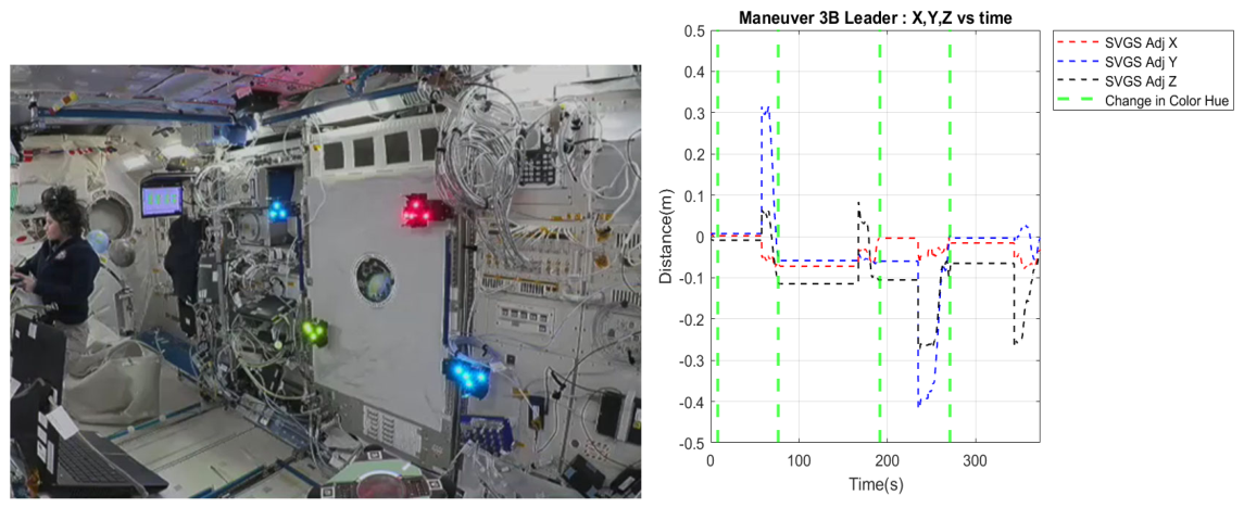
Figure 17.
(left) Hardware-in-the-loop (HIL) simulation of maneuver 3B using Gazebo and an Inforce 6640SBC single board computer and camera. (right) Maneuver 3B experimental data, SVGS Science 3. XYZ robot coordinate vs. time are shown in solid trace (red, blue, black) while the corresponding SVGS readings are shown in dotted lines. The changes in color of interest are shown as vertical green traces. Maneuver 3B demonstrates range extension with error correction based on SVGS readings, and handover based on different hues.
Figure 17.
(left) Hardware-in-the-loop (HIL) simulation of maneuver 3B using Gazebo and an Inforce 6640SBC single board computer and camera. (right) Maneuver 3B experimental data, SVGS Science 3. XYZ robot coordinate vs. time are shown in solid trace (red, blue, black) while the corresponding SVGS readings are shown in dotted lines. The changes in color of interest are shown as vertical green traces. Maneuver 3B demonstrates range extension with error correction based on SVGS readings, and handover based on different hues.
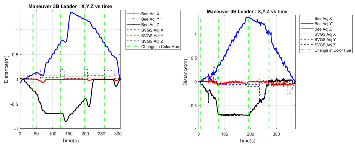
Figure 18.
Maneuver 3B, SVGS Science 3. (left): robot trajectory on YZ plane, (right): changes in Euler angles as robot transitions from one target to the next. Green dotted lines show a change in color of interest. The trajectory in the YZ plane highlights the system’s ability to maintain stable control during handover transitions.
Figure 18.
Maneuver 3B, SVGS Science 3. (left): robot trajectory on YZ plane, (right): changes in Euler angles as robot transitions from one target to the next. Green dotted lines show a change in color of interest. The trajectory in the YZ plane highlights the system’s ability to maintain stable control during handover transitions.
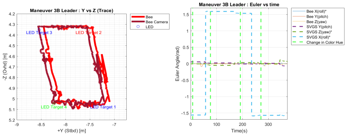
In summary, SVGS Science 3 included two SVGS maneuvers (3A and 3B). HIL simulations were used to verify the correct functionality of the APK, before running the actual data capture maneuvers on ISS. The data collected during SVGS Science 3 on 09/20/2022 demonstrates range extension and handover with SVGS; Maneuver 3B demonstrated the use of incremental motion commands for error-based navigation.
Maneuver 4 (SVGS Science Session 4) combined multi-target navigation with leader–follower formation flight in a single maneuver, as shown in Figure 19. The leader robot navigates through the multi-target sequence, while the follower attempts to maintain a fixed relative position based on SVGS measurements. This configuration requires relative pose estimation, and inter-agent coordination under conditions where visual occlusions and geometric constraints may degrade localization performance. The execution sequence begins with the follower moving to its initial position and establishing SVGS tracking at a sampling rate of 5 Hz, after which the leader initiates the multi-target maneuver.
Results from Maneuver 4 (Figure 19, left) reflect a breakdown in the native Astrobee localization framework on the Follower robot, leading to a loss of navigation stability. The leader’s location at the start of the maneuver lead to partial occlusion of the localizer’s reference surface: the lack of sufficient visual features, combined with the proximity of the leader’s beacon as a strong light source, leads to degraded performance in Astrobee’s native localization system. As a result, the follower is unable to maintain stable motion, highlighting a critical limitation in the proposed architecture to support formation flight. This underscores the necessity of integrating SVGS within a sensor fusion framework, where complementary sensing can ensure robust performance under a wider range of operational conditions [14].
The SVGS Science Sessions on ISS demonstrate that the SVGS system can provide accurate and consistent 6-DOF pose estimation in spacecraft, supporting both single-agent navigation and formation flight. The successful execution of Maneuvers 1 through 3 confirms that the system can maintain stable tracking in dynamic conditions, and handle transitions between multiple targets without loss of estimation coherence. Results from Maneuver 4 highlight the limitation associated with relying on a single sensing modality in a complex environment, particularly in map-based systems where localization performance can be compromised by partial occlusions of the line of sight. These findings suggest future development emphasizing the importance of sensor fusion to achieve robust localization to fully realize vision-based navigation systems for autonomous proximity operations and formation flying in space applications.
1.2. uVGS-2: Micro Video Guidance Sensor Version 2.0
The evolution toward the Micro Video Guidance Sensor (uVGS-2) starts with the Advanced Video Guidance Sensor (AVGS) [15], a vision-based navigation system developed at NASA Marshall Space Flight Center for autonomous rendezvous and docking of spacecraft. AVGS [16] was designed to estimate the full six-degrees-of-freedom (6-DOF) relative state vector between a chaser and target spacecraft by active optical sensing [17]. The system used a laser-based illumination source to excite a constellation of retro-reflective targets mounted on the client vehicle, generating high-contrast features in the image plane of a radiation-tolerant, high-resolution CMOS sensor. The detection pipeline relied on precise centroid extraction of the illuminated markers, followed by the application of inverse perspective and photogrammetric reconstruction techniques to recover the relative pose. AVGS was demonstrated in missions such as DART and Orbital Express [15], where it provided real-time relative navigation data under stringent dynamic and illumination conditions. Despite its high accuracy and flight heritage, AVGS had significant constraints in mass, power consumption, and hardware complexity, limiting its applicability in smaller spacecraft platforms such as cubesats.
The Smartphone Video Guidance Sensor (SVGS) was introduced as a low-cost, low-mass, highly portable implementation of the AVGS concept, leveraging commercial off-the-shelf (COTS) hardware [11]. SVGS replaced specialized illumination, optical sensing and processing hardware with a smartphone that integrates a camera, flash illumination, and embedded CPU [18]. The system retained the core photogrammetric framework, solving the Perspective-4-Point (P4P) problem to estimate the 6-DOF pose of a target relative to the camera frame. The algorithm was implemented in Java for Android, enabling rapid deployment and accessibility while maintaining sufficient computational performance for near real-time operation. SVGS can be seen as a “software-defined sensor,” abstracting hardware dependencies and allowing simple integration into diverse robotic platforms. To deploy SVGS on NASA’s Astrobee using both camera and CPU of the host robot, a modified implementation was developed by Jaycon Systems and Florida Tech: the “headless” SVGS variant, that eliminated smartphone-specific interfaces and dependencies, and demonstrated successful in-orbit operation during the SVGS Science Sessions on aboard ISS presented on Section 1.1, validating the feasibility of software-based vision-based pose and attitude sensor using host-platform resources .
The Micro Video Guidance Sensor (uVGS) represented a significant transition toward real-time, embedded, and hardware-agnostic implementations. Developed at NASA MSFC, uVGS was implemented in C language to enable deterministic execution in real-time computing platforms such as field-programmable gate arrays (FPGAs) [19]. The codebase was restructured as modular libraries of C functions. uVGS was designed as an “agnostic engine,” decoupled from specific camera drivers or hardware interfaces, facilitating portability and deployment in a wide range of configurations [20]. Validation of uVGS was primarily done with synthetic images, allowing statistical evaluation of algorithmic performance, independent of hardware-induced variability. This abstraction enabled assessment of the core photogrammetric and optimization routines, particularly in the context of solving the nonlinear pose estimation problem [17]. The transition to C also improved computational efficiency and memory management, critical for deployment in resource-constrained embedded systems.
The uVGS-2 system represents the next step up of this evolutionary trajectory, integrating advances in software architecture, numerical optimization, and image processing. Developed at Florida Institute of Technology in collaboration with NASA MSFC (EV41), uVGS-2 is implemented in C++, enabling modular design, extensibility, and seamless integration with modern robotic systems. A key feature of uVGS-2 is its deployment as a node within the Robot Operating System (ROS), allowing interoperability with a wide range of sensors, controllers, and autonomy frameworks in both aerial and ground robotic platforms. This architecture facilitates rapid prototyping of complex autonomy pipelines. The transition to C++ also enables the use of programming paradigms such as encapsulation, inheritance, and template-based optimization, which contribute to improved maintainability and scalability of the codebase. Another significant advancements in uVGS-2 is in its enhanced image pre-processing pipeline, which has been substantially expanded relative to previous versions.
uVGS-2 incorporates multi-stage image conditioning, including spatial decimation to reduce computational load, adaptive thresholding based on min-max intensity scaling (to handle variable illumination), and the application of Gaussian and median filters to suppress high-frequency noise. Intensity masking is used to isolate regions of interest, while advanced blob detection is achieved through contour tracing algorithms that accurately delineate feature boundaries. Morphological operations, such as erosion and dilation, are used to refine blob structures, eliminate spurious detections, and improve the robustness of centroid extraction. These enhancements enable reliable blob detection in challenging visual environments, including scenarios with non-uniform lighting, background clutter, and partial occlusions.
uVGS-2 also introduces refined camera calibration models, incorporating advanced methods for compensating lens distortion, critical for geometric consistency in wide-field camera systems. By applying distortion correction models prior to pose estimation, the algorithm reduces systematic errors in feature localization, improving accuracy of the reconstructed 3D state. Furthermore, a new geometry validation module has been implemented to ensure that detected feature configurations conform to the expected spatial arrangement of the target pattern. The module performs consistency checks based on inter-point distances and angular relationships, enabling robust rejection of false positives, enhancing the reliability of blob identification. At the core of uVGS-2 lies a highly optimized solver for the P4P problem, incorporating a novel analytical formulation of the Jacobian matrix associated with the reprojection error. Unlike previous implementations that relied on numerical approximation of derivatives, uVGS-2 leverages Lie algebra to derive a closed-form expression for the Jacobian, significantly improving computational efficiency and numerical stability. The analytical approach eliminates the need for iterative finite-difference calculations, reducing both computational overhead and susceptibility to numerical noise. The resulting optimization problem, formulated as a nonlinear least-squares minimization, takes advantage of the analytical Jacobian to achieve rapid convergence. This is particularly advantageous in real-time applications, where low latency and high update rates are essential for stable control and navigation.
The transition from AVGS [21] to SVGS, uVGS, and ultimately uVGS-2 reflects a progression towards portability, software abstraction, and computational efficiency, resulting in a sensing framework suitable for a broad spectrum of applications, from spacecraft proximity operations to robotics. uVGS-2 embodies advances in image processing, an advanced mathematical approach to solve nonlinear optimization in real-time, and modern embedded computing and software engineering practices, leading to a state-of-the-art solution for 6-DOF pose estimation in resource-constrained dynamic environments.
1.2.1. Technical Background and Initial Considerations of the uVGS-2 Mission on ISS
uVGS-2 was developed as a platform-independent, real-time 6-DOF pose estimation sensor to be deployed in NASA’s Astrobee free-flying robot. Unlike the SVGS-1 mission, where SVGS functioned as a custom application for the Guest Science Platform (HLP), the SVGS-2 Mission targets integration at the Mid-Level Processor (MLP), enabling direct interaction with Astrobee’s onboard localization and control pipelines. The mission objectives emphasize the validation of uVGS-2 as a complementary navigation sensor capable of supporting autonomous formation flight [22], rendezvous, and proximity operations in microgravity by means of sensor fusion with Astrobee’s native localization system (AstroLoc). The integration requires interfacing uVGS-2 output and Astrobee’s existing ROS-based software architecture using existing data handling pipelines.
The cameras available at Astrobee’s MLP (NavCam, DockCam, SpeedCam) are monochrome cameras, which degrades uVGS-2 performance since hue (color) cannot be used as part of the blob filtering logic for noise rejection. Use of a color camera stream (SciCam) available on the Guest Science module (HLP) was possible via an APK that published SciCam images to a topic available to MLP applications.
In formation flight maneuvers uVGS-2 functions as a relative navigation sensor, providing real-time estimates of the relative pose between the Follower and the beacon-equipped Leader. The leader executes predefined trajectories with respect to fixed reference frames (beacon_link), while the follower uses uVGS-2 measurements to maintain a prescribed relative position and orientation. The leader-follower paradigm introduces line-of-sight constraints, partial occlusions, and varying illumination conditions for the Follower, whose NavCam is affected by the illumination from the Leader’s beacon. Ground testing provides a controlled setting for parameter tuning, system calibration, and validation of integration interfaces.
The SVGS-1 mission demonstrated the feasibility of SVGS-based pose estimation, but highlighted challenges related to robustness, latency, and susceptibility to environmental disturbances that underscore the necessity of a sensor fusion paradigm, where uVGS-2 operates in conjunction with the native localization system rather than as an isolated sensor.
1.2.2. Sensor Fusion of uVGS-2 with Astrobee’s Localization Pipeline
Leader-follower maneuvers in the SVGS-1 mission revealed critical vulnerabilities associated with line-of-sight dependency and environmental interference, leading to degradation in localization performance due to occlusion of visual features by the leader robot, increased distance from reference surfaces, and the presence of high-intensity illumination from the SVGS beacon leading to loss of tracking and unstable control behavior. Reliance on far-field visual landmarks for localization can be mitigated if an additional pose sensor such as SVGS is available via sensor fusion [23].
Astrobee’s Graph-based Localizer (AstroLoc) uses a map-based factor graph framework to combine visual landmarks and inertial measurements to estimate the robot’s 6-DOF pose vector [24]. By incorporating uVGS-2 measurements as additional constraints within the factor graph, the system can maintain accurate state estimates even in the presence of partial occlusions or degraded illumination conditions. The implementation is based on transfer of uVGS-2 data to AstroLoc using the Docking camera pipeline. Approach and docking in Astrobee is based on AR tags located near Astrobee’s docking ports on ISS. The uVGS-2 integration strategy required modification of the existing localization pipeline, replacing the output of the AR tag detection module with the uVGS-2 measurement stream. The substitution is facilitated by the fact that both uVGS-2 and the AR tag detection module output a 6-DOF pose estimate relative to the camera frame, effectively transforming the AR pipeline into a uVGS-based localization source while preserving the underlying system architecture.
Other sensor fusion approaches were considered. A second approach incorporates uVGS-2 measurements as updates within an EKF framework, combined with inertial propagation from IMU data [25]. This enables continuous state estimation even in the absence of valid uVGS-2 measurements, leveraging inertial data to propagate the state between updates. The use of analytical IMU propagation, based on frameworks such as GTSAM and VINS, provides a computationally efficient means of integrating inertial measurements. A third approach involved incorporating uVGS-2 measurements within the AstroLoc factor graph architecture, enabling simultaneous optimization of all available measurements [24]. This provides the highest level of robustness and accuracy, as it accounts for correlations between different data sources and enables global consistency of the state estimate. The final choice of sensor fusion implementation (AR pipeline) reflected a balance between computational efficiency, integration complexity, and performance.
Fusion of uVGS-2 with AstroLoc enables reliable localization even under challenging conditions such as intermittent loss of beacon sight, illumination disturbances, and limited feature availability. Ground testing at NASA Ames’ Granite Lab demonstrated that the fused system sustains accurate localization in scenarios where standalone methods fail. In particular, the ability to maintain localization when the follower’s field of view is blocked by the leader represents a critical capability for formation flight operations. The fusion framework also enables the use of multiple cameras, including the integration of a color image stream (from the SciCam on HLP) to improve blob detection based on hue. The incorporation of adaptive weighting and gating within the fusion algorithm enables to selectively trust uVGS-2 measurements based on their quality, further enhancing robustness.
Sensor fusion reflects a broader paradigm shift in autonomous systems, where reliable operation in complex environments requires the integration of diverse sensing modalities. The uVGS-2 mission illustrates the advantages and implementation of sensor fusion in space robotics, providing a foundation for similar deployments in other map-based autonomous systems for proximity operations and formation flight.
1.2.3. Tetrahedral Beacons
Tetrahedral beacons provide a geometric configuration for robust and unambiguous 6-DOF photogrammetric pose estimation. A tetrahedral beacon is defined by a set of four non-coplanar fiducial points, typically implemented as actively illuminated LED markers, whose spatial arrangement guarantees a full-rank geometric structure in three-dimensional space, eliminating degeneracies associated with planar configurations. The set of vectors formed by the differences between beacon points is linearly independent, which enables the solvability of the Perspective-n-Point (PnP) problem in the minimal case of n = 4, where the tetrahedral configuration allows direct estimation of the relative pose from a single monocular image.
A tetrahedral geometry has inherent robustness against degeneracy in image-space projections, a limitation that commonly affects planar fiducial markers such as AR tags. In planar configurations, the projection of feature points onto the image plane can lead to ambiguous solutions, particularly under perspective distortion or when the viewing angle approaches a grazing incidence. In contrast, a tetrahedron preserves geometric diversity across all viewing directions. This improves the numerical conditioning of the pose estimation problem, enhancing convergence of nonlinear optimization algorithms. A tetrahedral configuration inherently avoids singularities associated with collinearity or coplanarity in the projected features, enabling stable and consistent pose recovery.
The SVGS beacons consists of four LEDs at precisely known coordinates in a local reference frame, with dimensions selected to balance detection range, angular resolution, and mounting constraints. A typical design places three markers forming a triangular base with a fourth marker at an offset along a perpendicular axis. The marker coordinates are inputs to the photogrammetric solver. The known geometry enables direct mapping between observed image features and their 3D locations, facilitating efficient and reliable solution of the P4P problem. Active illumination enhances detectability under low-light conditions, providing high-contrast features that can be robustly extracted through thresholding and blob detection techniques [26].
Following image acquisition and preprocessing, the system identifies candidate blobs corresponding to illuminated markers and extracts their centroid positions in image coordinates. A critical challenge is the correct association between detected blobs and their corresponding 3D beacon coordinates, a problem known as correspondence or data association. The tetrahedral geometry facilitates this process by enabling deterministic ordering of detected blobs based on geometric invariants, such as pairwise distances and relative orientation. For example, the longest baseline between two detected blobs can be used as a reference, while the relative position of the remaining blobs with respect to this baseline provide additional constraints for consistent labeling. This structured approach ensures that the input to the P4P solver is correctly labeled, eliminating ambiguities and preventing erroneous pose estimates. The ability to achieve consistent blob correspondence in real time is essential for the stability and accuracy of the estimation pipeline.
The P4P problem, which involves estimating the camera pose from four known 3D points and their corresponding 2D projections, represents the minimal configuration required for full 6-DOF pose recovery. By leveraging the tetrahedral geometry, uVGS-2 can use optimized analytical or iterative solvers with low computational overhead while maintaining high numerical accuracy. This is particularly important in resource-constrained environments such as the Astrobee platform, where processing power and memory are limited.
The incorporation of a Lie algebra-based analytical formulation of the optimization Jacobian matrix enhances numerical stability and eliminates the need for computationally expensive finite-difference approximations, significantly improving the computational performance of uVGS-2.
Tetrahedral beacons are not immune to geometric degeneracies, particularly under extreme viewing angles or in the presence of measurement noise [26]. When the projection of the beacon points onto the image plane approaches collinearity, the discriminative power of the solution is reduced, affecting the accuracy of the pose estimation. Similarly, symmetric arrangements or near-equal pairwise distances between points can introduce ambiguities in correspondence determination. These issues can be mitigated by the beacon geometry, ensuring that the spatial distribution of blobs maximizes geometric diversity and avoids symmetric configurations. uVGS-2 incorporates validation mechanisms to detect and reject degenerate configurations, such as thresholding based on inter-point distances and consistency checks on the reconstructed geometry. These safeguards ensure that only reliable blob sets are used in the estimation process, enhancing robustness and preventing propagation of erroneous states.
By using geometric information from the target’s design, the system reduces reliance on environmental features and enhances performance in feature-sparse or visually degraded environments. This is particularly advantageous in space applications, where external features may be limited or unavailable: the tetrahedral beacon provides deterministic geometric information directly used in pose estimation.
2. Materials and Methods
The uVGS-2 framework was comprehensively redeveloped relative to the original SVGS. An enhanced multi-stage image preprocessing pipeline is used, along with a novel formulation for solving the Perspective-4-Point (P4P) problem, based on a Lie algebra linearization of the optimization Jacobian, and the Google Ceres library [7].
The preprocessing pipeline starts by transforming the raw image , where and denote discrete pixel coordinates in the image plane domain , into a normalized and noise-suppressed representation , maximizing feature separation in environments such as the International Space Station (ISS), where non-uniform lighting, reflections, and illumination noise degrade raw image quality.
The pose estimation problem is formulated as a nonlinear least-squares optimization over the Special Euclidean group , where the rigid-body transformation is defined as , with representing the rotation matrix satisfying and , and represents the translation vector. For a given set of 3D fiducial points expressed in the target frame, their projection into the image plane is defined as , where is the intrinsic camera matrix and denotes the perspective division mapping homogeneous coordinates to pixel coordinates. The optimization minimizes the reprojection error defined as , where is the observed centroid of blob and is the predicted projection. Unlike standard implementations that rely on numerical differentiation to estimate the Jacobian of the error surface, uVGS-2 derives the Jacobian analytically using the Lie algebra , where is the minimal representation of the pose increment in the tangent space, composed of three rotational and three translational components. This formulation enables linearization of the nonlinear optimization problem as , significantly improving convergence rate, numerical stability, and computational efficiency, which are essential for real-time deployment in resource-constrained platforms.
2.1. Image Preprocessing
Image preprocessing in uVGS-2 is a sequence of transformations applied to the raw image , that generates a binary segmentation that improves detectability of fiducial markers while suppressing noise and irrelevant background structures. The process begins with spatial decimation, defined as , where is a scaling factor reducing resolution from to , decreasing computational load while preserving salient structures. Intensity normalization is then applied, using min-max scaling , where and are the minimum and maximum pixel intensities in the decimated image, ensuring that the dynamic range is mapped to . Normalization stabilizes subsequent thresholding under varying illumination conditions. A Gaussian filter is then applied, defined as , where denotes convolution and is the Gaussian kernel with standard deviation , which controls the level of smoothing. This operation attenuates high-frequency noise components while preserving low-frequency structures (fiducial markers).
Adaptive thresholding is then applied to generate a binary image defined as if , and otherwise, where the threshold is computed locally as , with and the mean and standard deviation of intensities within a local window , and a tuning parameter. This formulation enables robust segmentation under varying illumination conditions.
The binary image is further refined using morphological operations. Erosion is defined as , and dilation as , with a structuring element. Erosion removes small isolated noise regions, while dilation restores valid features; their combination in opening and closing operations provides noise suppression with structural preservation.
The final output of preprocessing is a binary image in which fiducial markers appear as well-defined connected components. Preprocessing is implemented to be configurable, allowing parameters such as , , , and structuring element size to be tuned dynamically (via launch file) to accommodate sensor characteristics and environmental conditions (low-light environment, high dynamic range, cluttered background).
2.2. Blob Finding and Blob Selection
Blob detection in uVGS-2 is a critical feature extraction step that must be robust to environmental variability and noise. Following generation of the binary image , connected components are identified as candidate blobs. Connectivity (8-neighborhood criterion) ensures that all pixels within a blob are spatially contiguous. The boundary of blob candidates is then extracted by a contour-following algorithm derived from the Suzuki-Abe method, which traces only the outer contours , and avoids hierarchical contour processing, which is justified since blobs are solid luminous regions without holes [12]. Contour representation supports downstream processing that requires ordered boundary information. Blob detection scales linearly with the number of pixels, ensuring deterministic execution time.
Candidate blobs are processed to identify spurious blobs. The primary descriptor is area , computed from the zeroth-order spatial moment , representing the number of pixels in the blob. The centroid is computed using first-order moments and , providing a subpixel estimate of blob location. Shape characterization uses the circularity metric , where is the perimeter derived from the contour length: circularity ~1 is consistent with the expected projection of LED-based markers. Additional geometric descriptors for feature validation are bounding box dimensions and aspect ratio. Hue information is extracted in the HSV space, enabling additional discrimination in scenarios with background clutter or reflective surfaces.
A blob is retained if it satisfies , , and , where thresholds are determined based on marker geometry, camera resolution, and operational distance. Thresholds can be adapted to environmental conditions (illumination levels, noise) via parameters available in a launch file.
Blob set candidates are evaluated using minimum and maximum allowable distances between candidate blobs based on the known dimensions of the tetrahedral beacon. This reduces the candidate set to a single subset that is used for P4P pose estimation. Only high-confidence blobs sets are passed to subsequent stages.
2.2.1. uVGS-2 Features
uVGS-2 is implemented in C++, facilitating modularity and integration within robotic systems. uVGS-2 is deployed as a node within the Robot Operating System (ROS), leveraging its publish–subscribe communication model to exchange data with other subsystems such as localization, guidance, and control modules [20]. The output of uVGS-2 is the estimated beacon pose in the camera coordinate frame, published at rates compatible with motion control requirements.
Since uVGS-2 can operate on images published by any ROS camera node of compatible image format, it becomes independent from specific camera drivers and sensor interfaces, which enables compatibility with a wide range of imaging systems and hardware platforms, such as monocular or stereo cameras, and a diversity of lens configurations and distortion models. The uVGS-2 camera model is defined through an intrinsic matrix , that incorporates focal lengths and principal point offsets, while distortion is modeled using parameterized functions that are calibrated offline. uVGS-2 supports both single-channel and multi-channel image processing, enabling operation with both monochrome and color cameras, but color image streams give better performance since hue can be used to filter reflections or bright objects from blobs.
uVGS-2 is optimized for deterministic real-time performance through multi-threading and efficient resource management. Image preprocessing and blob detection, are parallelized to exploit available CPU cores, reducing latency and increasing throughput. uVGS-2 can deliver high-frequency pose updates without exceeding available computational resources, maintaining compatibility with other onboard processes [27].
The pose estimation engine leverages state-of-the-art optimization libraries (Google Ceres) to achieve high accuracy with reduced computational overhead [4]. uVGS-2 modular architecture and compatibility with both ROS and ROS2 [28], enables integration with autonomy pipelines; the ability to operate as a standalone sensor or as part of a sensor fusion framework positions uVGS-2 as a state-of-the-art solution for vision-based navigation in both spacecraft [29] and robotics applications.
2.2.2. Blob Sorting in uVGS-2
Blob sorting addresses the deterministic correspondence problem between detected image-space features and their known three-dimensional counterparts defined by the tetrahedral beacon geometry. Following blob selection, the system operates on a reduced candidate set , where each blob is characterized by its centroid coordinates in the image plane. The objective of blob sorting is to establish a bijective mapping between the detected centroids and the ordered set of 3D fiducial points , where are expressed in the beacon reference frame. The approach is based on geometric invariants that are preserved under projective transformations, specifically pairwise Euclidean distances and relative orientation relationships in the image plane. The algorithm begins by computing the complete set of pairwise squared distances , forming a symmetric distance matrix that encodes the spatial distribution of the detected points. The maximum distance corresponds to the longest projected edge of the tetrahedral configuration, and the associated point pair is designated as the primary baseline. This baseline serves as reference axis for subsequent ordering operations, reducing the combinatorial complexity of the correspondence problem and enabling deterministic assignment in finite time.
After baseline identification, the algorithm computes the midpoint of the baseline endpoints and evaluates the relative positions of the remaining two points with respect to this midpoint. The distances are computed for the remaining blobs, and used to classify the points within the tetrahedral structure, exploiting the asymmetry of the tetrahedral geometry, where the projection of the apex point differs from that of the base vertices [4]. By assigning the closer point to the midpoint as one vertex and the farther point as another, the algorithm establishes a partial ordering that is invariant to global translation and rotation in the image plane. This step significantly reduces ambiguity and ensures consistent labeling across frames, even under varying viewing conditions [4]. The robustness of this approach is particularly important in dynamic scenarios where the relative orientation between camera and beacon changes continuously, requiring the sorting algorithm to maintain consistency without reliance on temporal tracking.
To finalize ordering and eliminate potential mirror ambiguities, the algorithm employs an orientation test based on the sign of the cross product between vectors defined in the image plane. For three points , the scalar cross product is calculated, where the sign of indicates the orientation (clockwise or counterclockwise) of the triplet. This ensures that the ordering of points is consistent with the known orientation of the tetrahedral geometry in 3D space, resolving ambiguities that could otherwise lead to incorrect pose estimates [12]. Orientation tests provide a computationally efficient mechanism for enforcing geometric consistency, avoiding the need for exhaustive permutation searches or probabilistic matching techniques. The blob sorting algorithm also includes validation checks to detect degenerate configurations, such as near-collinear projections or insufficient spatial separation between points, which may compromise the reliability of the sorting process.
Blob sorting operates in real time with deterministic execution time. Its reliance on geometric relationships ensures both efficiency and robustness, enabling consistent correspondence even in the presence of noise, partial occlusions, or perspective distortions. Probabilistic sorting methods may introduce variability in execution time or outcomes. By providing a consistent and unambiguous mapping between image-space observations and 3D model points, blob sorting ensures that the P4P solver operates on valid inputs.
2.2.3. Engine Solver
The engine solver in uVGS-2 is the core computational module responsible for estimating the six-degrees-of-freedom pose of the target relative to the camera frame, formulated as a nonlinear optimization problem over the Special Euclidean group . The objective is to determine the transformation that minimizes the reprojection error between observed image points and the projections of known 3D points under the estimated pose. The projection model is defined as , where is the intrinsic camera matrix containing focal lengths and principal point coordinates, and denotes the perspective division operation mapping homogeneous coordinates to pixel coordinates. The optimization problem is expressed as the minimization of the cost function , where the summation is performed over the four fiducial points of the tetrahedral beacon. This formulation ensures that the estimated pose minimizes the discrepancy between observed and predicted feature locations in a least-squares sense, providing an optimal solution under Gaussian noise assumptions [20].
A key innovation of the uVGS-2 solver lies in the use of Lie algebra to derive an analytical Jacobian for the optimization, enabling efficient and numerically stable linearization of the nonlinear optimization problem. The pose increment is represented as a vector , where represents the rotational component and the translational component of the pose estimate. The transformation update is expressed through the exponential map , where is the skew-symmetric matrix representation of . The Jacobian is derived analytically by differentiating the reprojection error with respect to the pose parameters, eliminating the need for numerical finite-difference approximations. This analytical formulation significantly reduces computational overhead and improves numerical accuracy, particularly in scenarios with small perturbations or at high update rates. The linearized system is then solved iteratively using methods such as Dogleg and Dense Schur optimization, ensuring rapid convergence to the optimal solution [12]. The solver incorporates convergence criteria based on the norm of the update vector and the reduction in cost function , ensuring that iterations terminate when a stable solution is reached. The solver includes validation tests to assess the quality of the estimated pose based on error residuals and geometric consistency checks. The uVGS-2 engine delivers accurate and stable pose estimates with state-of-the-art computational performance, as needed on resource-constrained applications.
2.3. NASA’s Astrobee Localization System (AstroLoc)
NASA’s Astrobee free-flying robot uses a localization framework, AstroLoc [30], based on a Visual-Inertial Navigation System (VINS) architecture adapted to the operational constraints of the International Space Station. Unlike terrestrial VINS implementations that rely heavily on inertial excitation and abundant environmental features, AstroLoc is designed to operate under microgravity conditions, where the absence of persistent gravitational acceleration significantly alters the observability of inertial states [31]. The system is also constrained by the limited computational resources of the onboard avionics, necessitating an architecture that prioritizes efficiency, robustness, and deterministic execution [4]. To address these constraints, AstroLoc adopts a graph-based optimization framework built upon the Georgia Tech Smoothing and Mapping library (GTSAM), in which the robot’s trajectory is represented as a factor graph composed of nodes (corresponding to discrete robot poses) and edges (representing measurement constraints derived from visual features and inertial data). The state vector at each node includes position , orientation , velocity , and IMU bias terms, while constraints are introduced through visual feature observations and pre-integrated IMU measurements. AstroLoc uses a feature map-based approach, where previously observed features are stored and re-associated across time to provide long-term consistency and mitigate drift [4]. This is particularly advantageous in the ISS environment, where repeated geometric patterns and limited feature diversity can thwart traditional loop-closure methods. The resulting optimization problem is solved incrementally, allowing real-time updates to the robot’s estimated state while maintaining global consistency across the trajectory[32].
Astrobee’s localization system can operate in multiple modes, including a docking mode that leverages binary fiducial markers (AR tags) as primary features for pose estimation. In this configuration, the corners of the fiducial markers are detected and incorporated into the factor graph as high-confidence visual landmarks, enabling precise relative localization during docking maneuvers [33]. However, this mode is segregated from the standard navigation pipeline, which relies on FAST (Features from Accelerated Segment Test) corner detection and tracking for general motion estimation. The localization system selects between pipelines depending on the operational context, which limits the simultaneous use of heterogeneous feature types, which introduces constraints on extensibility and limits the integration of additional sensing modalities [4].
The fusion of uVGS-2 with Astroloc extends the non-docking localization pipeline to incorporate target-derived features, cloning the AR tag processing chain and integrating it into the general pose-graph framework. This enables the fusion of external features such as those provided by uVGS-2 directly into the factor graph, allowing simultaneous utilization of environmental features and uVGS-2 observations, both static and dynamic.
The proposed framework accommodates multiple camera modalities, including the color Science Camera (SciCam) and the monochrome Navigation Camera (NavCam), both of which are characterized by known camera-to-IMU extrinsics. These enhancements transform AstroLoc into a multi-sensor fusion framework [34], while maintaining the robustness and efficiency of the original AstroLoc system.
2.4. uVGS-2 in Astrobee – Sensor Fusion
During the SVGS-1 mission, SVGS was used as an external measurement source, operating independently from the robot’s native localization pipeline, which showed critical limitations under conditions involving line-of-sight obstruction and disturbances induced by active beacon illumination. These effects resulted in degradation of Astrobee’s native localization, which relies on environmental features, compromising control performance. uVGS-2 was designed for direct integration with the Astrobee software stack as a ROS-compliant node executing on the Mid-Level Processor (MLP), enabling real-time exchange of state information with the Graph-based Localizer. This required a software interface to transfer 6-DOF pose estimates from uVGS-2 into Astrobee’s localization framework [35].
The integration was successfully demonstrated with both NavCam (monochrome) and SciCam (color) image streams. uVGS-2 outputs were formatted to use the interface of the existing AR Tag pipeline, allowing direct substitution of fiducial marker measurements with minor modifications to the downstream processing chain [36], preserving compatibility with the factor graph optimization framework underlying AstroLoc. uVGS-2 could be deployed both as a standalone pose estimator and as an integrated component within the sensor fusion scheme, with the latter providing superior robustness in scenarios involving occlusions and dynamic lighting disturbances.
Sensor Fusion between uVGS-2 and AstroLoc involves augmenting Astrobee’s native Map Landmark (ML) pipeline—based on sparse visual features, with externally derived pose estimates from uVGS-2, generated from beacon tracking. uVGS-2 measurements are injected as high-confidence visual landmarks via a modified AR Tag pipeline. Rather than introducing a separate localization mode, the system uses compile-time flags to modify the behavior of the AR pipeline, enabling selective use of both ML and uVGS-derived measurements. This approach ensures that the estimator can balance contributions from environmental features and beacon observations, mitigating the limitations associated with each individual modality [20].
A critical aspect of this fusion strategy is the ability to maintain localization continuity in scenarios where one sensing modality becomes unreliable. For instance, when the follower robot’s field of view is obstructed by a leader vehicle or when strong illumination from the beacon degrades feature detection, the ML pipeline may fail to provide sufficient features for accurate state estimation. In such cases, uVGS-2 measurements provide direct relative pose information that preserves estimator observability. Conversely, when beacon visibility is temporarily lost, the ML pipeline continues to propagate the state using environmental features and inertial data. This behavior is facilitated by the factor graph formulation, which inherently supports asynchronous and heterogeneous measurements. Experimental results from ground testing at NASA Ames demonstrate that this fusion approach enables stable localization even under extreme conditions, including complete visual blockage, sensor saturation or loss of line of sight with a beacon.
2.5. Build and Test uVGS-2 in Astrobee – Implementation Considerations
Ground experiments at NASA Ames’ Granite Lab allowed to evaluate functionality and performance of the proposed approach under representative operational conditions. uVGS-2 modifications included the configuration of camera intrinsic parameters, adaptation to Astrobee-specific image topics, and integration with the ff_msgs::VisualLandmarks message interface for publishing pose estimates. Successful deployment was verified through real-time execution on the MLP, where uVGS-2 processed incoming image streams and generated 6-DOF pose estimates corresponding to the relative position and orientation of the beacon with respect to the camera frame. Data logging was done via ROS bag files, capturing synchronized streams of camera data, pose estimates, and EKF outputs for post-processing analysis. Sensor Fusion of AstroLoc and uVGS-2 was implemented through a modification of the AR Tag pipeline, enabling direct substitution of AR tag measurements with uVGS pose estimates: the ARVisualLandmarksCallback function was modified to process uVGS-generated measurements, and the Sparse Mapping pipeline was extended to operate concurrently with the modified AR pipeline, enabling simultaneous use of environmental features and UVGS-2 measurements. The dual-pipeline configuration transforms the localization system into a sensor fusion framework [32].
3. Experimental Results
3.1. NASA ARC’s Granite Lab – Ground Testing Considerations
Ground testing at NASA Ames Research Center’s Granite Lab intends to replicate the computational, kinematic and perceptual constraints associated with proximity operations on ISS. The Granite Lab provides a low-friction air-bearing floor that enables motion in three degrees of freedom (X, Y, and yaw), preserving the geometric relationships necessary for 6-DOF pose estimation using vision-based sensing [37].
Granite Lab testing also reproduces implementation constraints related to actual deployment on Astrobee. The Astrobee Mid-Level Processor (MLP), which hosts the UVGS-2 ROS node, imposes computational limitations in terms of CPU utilization, memory bandwidth, and real-time scheduling. The absence of color imaging capabilities in the MLP—limited to monochrome NavCam and DockCam streams—introduced challenges in blob detection and false-positive rejection, as hue-based filtering could not be used. Other issues that need to be considered in uVGS-2 deployment on Astrobee are camera intrinsic calibration, field-of-view distortion modeling, and coordinate frame consistency between uVGS-2 outputs and factor graph representation.
The development of motion control strategies based on uVGS-2 feedback prompted the implementation of a hardware-in-the-loop (HIL) simulation framework. A 3-DOF gantry was built to emulate beacon motion (Figure 20), enabling validation of motion control algorithms and perception-action coupling via NASA’s Rviz and Gazebo Astrobee simulation framework, enabling testing of leader-follower dynamics and debugging of synchronization and computational constraints within the MLP architecture.
HIL-simulation of perception and control is shown in Figure 21 (HIL simulation of the follower’s motion node). The Follower code (MoveUVGS) sends motion commands created based on 6-DOF pose updates published by the UVGS-2 node. In the HIL simulation, real-time input from an Intel D455 camera is used to detect beacon features and compute the beacon’s 6-DOF pose estimates, which are then used to generate motion commands within NASA’s Astrobee Gazebo simulation environment. The closed-loop architecture demonstrates feasibility of real-time vision-based control using uVGS-2 outputs.
3.2. Experiment GT1: Testing and Demonstration of uVGS-2 Deployment on Astrobee
Ground test experiment GT1 focused on demonstrating deployment and functionality of uVGS-2 in Astrobee. The experiment involved build and deploy the uVGS-2 code as a ROS-compatible C++ node to run on Astrobee’s MLP. This required modifications to accommodate Astrobee-specific camera interfaces, including the definition of intrinsic parameters, adaptation to ROS image topics, and integration with the ff_msgs::VisualLandmarks message structure for publishing 6-DOF pose estimates. uVGS-2 was deployed via a dedicated ROS workspace and compiled using catkin, with execution controlled from the SSH command line [11]. Correct operation was verified by monitoring the publication of pose messages and checking consistency between estimated beacon positions and known robot-beacon configurations for several distances and orientations.
RViz enabled real-time confirmation that the system could track beacon motion and detect all 4 beacon blobs during testing, with measurement outputs showing correlation with ground truth obtained through manual displacement and ruler-based measurements. uVGS-2 deployment in Astrobee was demonsatretd with both NavCam and DockCam, although some performance degradation (failure to detect all 4 blobs during tests) was noticed due to the inability of monochrome imaging to use hue-based blob filtering. The experiment established the feasibility of deploying uVGS-2 as a ROS node on Astrobee, demonstrating its capability to operate in real time along with other MLP processes, and produce accurate 6-DOF pose estimates suitable for downstream integration with localization and control subsystems.
Figure 22 outlines Ground Test 1 (GT1), showing successful deployment of uVGS-2 as a ROS node running on Astrobee’s Mid-Level Processor (MLP). The figure shows the experiment layout and image processing results, including a raw NavCam image and post-processed visualization in RViz. The red markers overlaid on the processed image indicate successful blob detection and centroid extraction, which enables accurate estimation of the 6-DOF pose vector. Camera exposure, gain and uVGS-2 preprocessing parameters are editable in the corresponding launch file.
3.3. Ground Experiment GT2. Demonstration of Sensor Fusion: UVGS-2 as Data Stream That Replaces AR Tag Data in the AR Pipeline in Astrobee
Experiment GT2 runs UVGS-2 in Astrobee as a data stream that replaces the AR Tag data stream in the AR Pipeline, demonstrating the feasibility of substituting AR tag inputs with uVGS-2 measurements. In the modified AR pipeline, the UVGS-2 node publishes pose data to the same interface used by the marker_tracking package, enabling seamless integration of uVGS-2 into the existing factor graph framework. A secondary objective was to determine whether the fusion of UVGS-2 data could maintain localization continuity in an occlusion scenario, where the feature-based AstroLoc would fail. Ground experiments showed that Astrobee could maintain good localization with uVGS-AstroLoc fusion even when the robot’s view of the walls was significantly blocked, or when the beacon’s proximity caused sensor saturation.
GT2 demonstrated that UVGS-2 can replace the AR Tag data stream within the AR pipeline while preserving or enhancing the robustness of the localization system. In GT2, Astrobee successfully processed simultaneous inputs from both the Map Landmark (ML) and UVGS-modified AR pipelines, demonstrating the viability of a dual-input factor graph architecture. Localization performance remained stable even under conditions of partial or complete occlusion, since UVGS-2 measurements provided sufficient geometric constraints to maintain estimator observability. GT2 also revealed the need for careful tuning of factor graph weights to mitigate the impact of occasional false readings from the uVGS-2 pipeline, which could introduce localization error if not properly filtered. The absence of color information (monochrome cameras on MLP were used) limits the system’s ability to properly reject spurious reflections, highlighting the importance of using a color camera for optimal performance.
GT2 demonstrated full sensor fusion of uVGS-2 with Astrobee’s Graph-based Localizer through a modified AR pipeline, enabling simultaneous utilization of beacon-based and feature-based measurements within the unified AstroLoc estimation framework. The experimental setup involved commanding Astrobee to execute a square maneuver through a sequence of motion commands issued via the Ground Data System (GDS), while recording localization outputs under two configurations: (i) native Map Landmark (ML) pipeline only, and (ii) fused ML + uVGS-2 pipeline, where the uVGS-2 node continuously published pose estimates derived from beacon observations, which were injected into the factor graph as visual landmarks via the modified AR interface. Data recording (ROS bags) included EKF outputs, uVGS-2 6-DOF pose, camera streams, ground truth, and feature topics (both ML and AR features), enabling comprehensive post-processing analysis of localization performance.
An outline of the test setup at Ames’s Granite Lab is shown in Figure 23 (left). Localization results from the robot (XY coordinates) after commanding square maneuvers as a sequence of four move commands from the GDS, are shown in Figure 23 (right). Motion performance when using the native Map Landmark pipeline (red trace) can be compared to motion performance when using the fused uVGS-2 + Map Landmark solution (blue trace), showing improved motion control performance achieved through sensor fusion.
The experiment also highlights the limitations of using monochrome imaging, with reduced blob discrimination leading to increased susceptibility to false detections; this motivated subsequent integration of color image streams from SciCam to enhance robustness through hue-based filtering, via a HLP APK that publishes SciCam images as a ROS topic that can be read at the MLP.
Integration of uVGS-2 with AstroLoc via sensor fusion provides a robust and flexible localization solution for formation flight, even if the Follower’s view of the wall is blocked by the Leader, or if the Follower’s camera is blinded by close proximity of a SVGS beacon.
3.4. Ground Experiment GT-3: Demonstration of Leader Motion Node with uVGS- Fusion
GT-3 (Figure 24, Left) demonstrates a leader motion control node using fused uVGS-2 fused with AstroLoc localization to execute precise trajectory tracking. The experiment commands the leader robot to perform a square maneuver by two different methods: (i) Baseline: native AstroLoc with no sensor fusion, with manual motion commands issued through the GDS interface, and (ii) an autonomous motion script implemented as a ROS node with pose feedback from the fused localization system. A FIFO filter within the motion control node enables smoothing of pose estimates, improving command stability.
The image input stream is from a color camera (SciCam on HLP), publishing images to a topic that can be read by uVGS-2 on the MLP. The procedure to achieve UVGS-AstroLoc sensor fusion using the SciCam image stream is as follows: (i) HLP android APK publishes SciCam compressed images, (ii) Hue for SciCam depending on beacon color, is chosen in camera launch file, (iii) calibration Check (extrinsics and intrinsics), (iv) change UVGS Pipeline to compressed images, and to include HUE analysis, (v) the Astrobee Localizer factor graph has to consistently find world_t_dock (the transformation matrix representing the beacon’s position and orientation within the ISS coordinate frame) for the follower Astrobee, (vi) change Factor graph options for AR mode to use SciCam options, (vii) enable mixed graph (AR + Map Landmark), and (viii) change AR pipeline to accept uVGS-2 outputs rather than AR native input stream.
Results from the GT3 experiment are shown in Figure 25. The square maneuver was repeated twice: first using manual commands from the GDS terminal (left) and then using a Leader motion script (right). A significant enhancement in trajectory accuracy was achieved when the autonomous motion node was used, as compared to manual command execution via GDS. A residual vertical tilt (~ 20 mm) is attributed to mechanical misalignment in the air-bearing support system that holds Astrobee. Integration of uVGS-2 with AstroLoc not only enhances localization performance but also enables motion control that outperforms waypoint manual commands in the baseline system.
The extension of GT3 to multi-robot formation is outlined in Figure 24 (Right), which shows the home position for leader-follower maneuvers. The follower robot uses uVGS-2 measurements to track a beacon mounted on the leader, maintaining a prescribed relative pose throughout the maneuver.
GT4 results are shown in Figure 26, where the trajectories of both leader and follower are plotted in the XY plane. While the leader exhibits stable and accurate motion, the follower’s performance deteriorates as a result of CPU and resource limitations of the MLP when executing multiple motion commands. This underscores the importance of optimizing motion control algorithms and resource allocation in embedded GNC systems.
4. Discussion
This paper presents a comprehensive validation of uVGS-2 as a platform-independent vision-based 6-DOF position and attitude sensor, and confirms its suitability for integration into resource-constrained autonomous systems. The evolution from the original SVGS implementation to uVGS-2 includes substantial architectural and algorithmic advancement, particularly in its deployment as a ROS node, enabling modularity, scalability, and direct compatibility with robotic middleware frameworks. Advanced image preprocessing techniques enable tuning to environmental conditions that make uVGS-2 significantly more robust to illumination disturbances compared to SVGS, allowing robust performance across a wide range of illumination conditions, including high contrast scenarios and optical disturbances induced by active beacon sources [38]. Performance degradation in monochrome cameras highlights the importance of color-based filtering for robust blob discrimination. Successful deployment of uVGS-2 on Astrobee using both NavCam and SciCam confirms its adaptability to various sensor configurations and reinforces its applicability in spacecraft platforms [39].
The introduction of a Lie-algebra-based analytical expression of the P4P optimization Jacobian eliminates the need for numerical estimates of the gradient in convex optimization, significantly reducing computational overhead and making uVGS-2 suitable for deployment on resource-constrained hardware platforms, while enabling high update rates: up to 100 samples/sec in Astrobee, compared to 10 samples/sec achieved with SVGS.
Integration of uVGS-2 within Astrobee’s Graph-based Localizer [20,24] through sensor fusion constitutes a key contribution, enabling resilient localization. uVGS-2 can effectively replace AR Tag inputs within the localization pipeline (factor graph framework) enhancing estimator robustness in scenarios involving occlusions, beacon-induced illumination disturbances, and loss of environmental features. This is particularly relevant in formation flight, where intermittent loss of line-of-sight and proximity between vehicles create significant challenges in localization continuity. Successful implementation of uVGS- fusion allowed Astrobee to maintain accurate state estimation even when the follower’s field of view was obstructed by the leader or saturated by beacon proximity, addressing key limitations identified in prior SVGS deployment [12].
Motion control nodes demonstrated that uVGS-2-enabled localization facilitates improved trajectory tracking, surpassing GDS-based motion control in both accuracy and repeatability. The Leader-Follower maneuver was developed and successfully tested on Astrobee’s Gazebo environment as a hardware-in-the-loop (HIL) simulation, using an Intel D455 camera simulating the Leader’s motion to generate Follower’s motion commands, demonstrating accurate trajectory tracking [40]. Leader-Follower motion was then tested on two Astrobees at NASA Ames’ Granite Lab [41], with partial success. While the Leader motion performed as expected (GT3 experiment) the Follower motion did not behave as in the HIL simulation. Performance limitations in follower maneuvers are due to insufficient CPU capacity and computational resources in the MLP, exposed by the software execution overhead associated with the use of high-level motion control commands, highlighting the need of lower-level control implementations to realize autonomous multi-robot coordination. The motion scripts, running in parallel with uVGS-2 and several other native processes, seem to overwhelm the CPU capacity of the MLP.
uVGS-2 is a viable and competitive solution for proximity operations and formation flight in spacecraft, easily extendable to mobile robot platforms with different mechatronic configurations [42,43,44,45], via ROS. It evolved from a C-based implementation of SVGS into a modular, platform-independent ROS application capable of real-time execution in Astrobee’s Mid-Level Processor (MLP) [46]. This evolution enables portability across heterogeneous robotic platforms, and integration with ROS middleware frameworks.
5. Conclusions - Future Work
Ground Experiment GT-2 is a critical validation milestone for the integration of uVGS-2 with Astrobee’s localization architecture, by demonstrating fusion of uVGS-2 measurements with the Graph-based Localizer [20,24] via the AR pipeline. The experiment showed that Astrobee can simultaneously process measurements from multiple sensing pipelines, namely the Map Landmark (ML) pipeline and the modified AR pipeline populated with uVGS-2 pose outputs, without degradation in estimator stability. This dual-input capability represents an important robustness improvement in onboard localization, as it enables redundancy and complementary sensing modalities within Astrobee’s native factor graph framework (AstroLoc). GT-2 findings establish that uVGS-2 measurements can substitute AR tag detections in the localization pipeline, expanding operational flexibility for proximity operations.
GT-2 illustrated the robustness of the uVGS-fusion framework under adverse operational conditions, as it maintained reliable localization in scenarios where the follower’s line of sight was obstructed by the leader, or where the follower’s camera was in close proximity to illuminated beacon sources, which would have lead to localization failure in the original localizer based on the ML pipeline alone. GT-2 also revealed limitations in the use of monochrome cameras with uVGS-2, due to the inability to use hue-based filtering for rejection of spurious blob detections from reflections or image noise. This motivated the use of the SciCam color image stream, enabling enhanced blob filtering through hue detection, significantly improving uVGS-2 performance. The adaptation of the uVGS-2 pipeline to process compressed color images, combined with camera calibration and factor graph tuning, underscores the flexibility of the proposed approach for deployment scenarios with diverse illumination conditions.
Experimental results from square trajectory maneuvers (GT-3) showed that the fused uVGS-ML solution maintains consistent and accurate pose estimation, with trajectory tracking performance superior to the baseline (ML-only) configuration. uVGS-2 has demonstrated to be a vision-based platform-independent relative position and attitude sensor, capable of real-time deployment in autonomous robotic systems. The evolution from the original SVGS and uVGS implementation to uVGS-2 introduced substantial improvements in computational efficiency, robustness, and integration capability, by the adoption of a ROS-based architecture, advanced image preprocessing, and a Lie-algebra-based computation of the optimization Jacobian that significantly reduces computational load and improves update rate by a factor of 10 relative to SVGS on HLP. Successful deployment of uVGS-2 on Astrobee’s Mid-Level Processor, along with its integration with AstroLoc via the AR localization pipeline, confirms the feasibility of using uVGS-2 as either primary or complementary pose sensor for proximity operations. The system demonstrated reliable performance across a range of operational scenarios, including those involving degraded visibility and partial occlusions of the line of sight, validating its applicability to formation flight and cooperative robotics missions. uVGS-2 is a viable and scalable solution for autonomous navigation and motion control in space environments, drones and mobile robot platforms.
Author Contributions
Conceptualization, H.G. and I.B.; methodology, H.G.; validation, H.G. and I.B.; formal analysis, H.G and J.C.; investigation, H.G and J.C.; resources, H.G. and I.B; data curation, H.G.; writing—original draft preparation, H.G and J.C.; writing—review and editing, H.G and J.C.; visualization, H.G.; supervision, H.G and I.B.; project administration, H.G.; funding acquisition, H.G and I.B. All authors have read and agreed to the published version of the manuscript.
Funding
This study was supported by NASA’s Marshall Space Flight Center, Cooperative Agreement 80NSSC21M0262 and 80NSSC24M0057, Dual-Use Technology Development, CAN 2021, 2023.
Conflicts of Interest
The authors declare no conflicts of interest.
References
- Hariri, N.; Gutierrez, H.; Rakoczy, J.; Howard, R.; Bertaska, I. Proximity operations and three degree-of-freedom maneuvers using the smartphone video guidance sensor. Robotics 2020, 9, 70. [CrossRef]
- Nesnas, I.A.; Fesq, L.M.; Volpe, R.A. Autonomy for space robots: Past, present, and future. Current Robotics Reports 2021, 2, 251-263. [CrossRef]
- Janousek, J.; Marcon, P. Precision landing options in unmanned aerial vehicles. In Proceedings of the 2018 International Interdisciplinary PhD Workshop (IIPhDW), 2018; pp. 58-60. [CrossRef]
- Silva, J. Towards Visual Inertial Navigation with Fixed Tetrahedral Targets. Dissertation, Florida Institute of Technology, May 2025.
- Kalinov, I.; Safronov, E.; Agishev, R.; Kurenkov, M.; Tsetserukou, D. High-precision uav localization system for landing on a mobile collaborative robot based on an ir marker pattern recognition. In Proceedings of the 2019 IEEE 89th Vehicular Technology Conference (VTC2019-Spring), 2019; pp. 1-6. [CrossRef]
- Howard, R.T.; Book, M.L.; Bryan, T.C. Video-based sensor for tracking three-dimensional targets. In Proceedings of the Atmospheric Propagation, Adaptive Systems, and Laser Radar Technology for Remote Sensing, 2001; pp. 242-251. [CrossRef]
- Becker, C.; Howard, R.; Rakoczy, J. Smartphone video guidance sensor for small satellites. 2013.
- Song, M.; Ou, Z.; Castellanos, E.; Ylipiha, T.; Kämäräinen, T.; Siekkinen, M.; Ylä-Jääski, A.; Hui, P. Exploring vision-based techniques for outdoor positioning systems: A feasibility study. IEEE Transactions on Mobile Computing 2017, 16, 3361-3375. [CrossRef]
- Civera, J.; Davison, A.J.; Montiel, J.M. Inverse depth parametrization for monocular SLAM. IEEE transactions on robotics 2008, 24, 932-945. [CrossRef]
- Mizuchi, Y.; Ogura, T.; Kim, Y.; Hagiwara, Y.; Choi, Y. Vision-based markerless measurement system for relative vessel positioning. IET Science, Measurement & Technology 2016, 10, 653-658. [CrossRef]
- Hariri, N.; Gutierrez, H.; Rakoczy, J.; Howard, R.; Bertaska, I. Performance characterization of the smartphone video guidance sensor as vision-based positioning system. Sensors 2020, 20, 5299. [CrossRef]
- Gutierrez, H. UVGS-2: Micro Video Guidance Sensor - Revision 2. ; NASA New Technology Report, e-NTR 1766866918, December 2025.
- Ye, R.; Tao, C.; Yan, B.; Yang, T. Research on vision-based autonomous landing of unmanned aerial vehicle. In Proceedings of the 2020 IEEE 3rd International Conference on Automation, Electronics and Electrical Engineering (AUTEEE), 2020; pp. 348-354. [CrossRef]
- Bautista, N.; Gutierrez, H.; Inness, J.; Rakoczy, J. Precision landing of a quadcopter drone by smartphone video guidance sensor in a gps-denied environment. Sensors 2023, 23, 1934. [CrossRef]
- Howard, R.T.; Bryan, T.C. DART AVGS flight results. In Proceedings of the Sensors and Systems for Space Applications, 2007; pp. 162-171. [CrossRef]
- Bryan, T.C.; Howard, R.; Johnson, J.E.; Lee, J.E.; Murphy, L.; Spencer, S.H. Next generation advanced video guidance sensor. In Proceedings of the 2008 IEEE Aerospace Conference, 2008; pp. 1-8. [CrossRef]
- Bertaska, I.R.; Rakoczy, J.M.; Dankanich, J.W. Micro Video Guidance Sensor: Versatile Relative Position Sensor for In-space and Surface Applications NASA TechPort; 2023 2023.
- Silva, J.; Rakoczy, J.; Gutierrez, H. Precision landing comparison between smartphone video guidance sensor and IRLock by hardware-in-the-loop emulation: JL Silva Cotta et al. CEAS Space Journal 2024, 16, 475-489. [CrossRef]
- Ahmad, J.; Warren, A. FPGA based deterministic latency image acquisition and processing system for automated driving systems. In Proceedings of the 2018 IEEE International Symposium on Circuits and Systems (ISCAS), 2018; pp. 1-5. [CrossRef]
- Blanco-Claraco, J.L. A tutorial on SE(3) transformation parameterizations and on-manifold optimization; Universidad de Malaga: 2022.
- Howard, R.T.; Heaton, A.F.; Pinson, R.M.; Carrington, C.K. Orbital express advanced video guidance sensor. In Proceedings of the 2008 IEEE Aerospace Conference, 2008; pp. 1-10. [CrossRef]
- Xin, L.; Tang, Z.; Gai, W.; Liu, H. Vision-based autonomous landing for the uav: A review. Aerospace 2022, 9, 634. [CrossRef]
- Zhao, B.; Chen, X.; Zhao, X.; Jiang, J.; Wei, J. Real-time UAV autonomous localization based on smartphone sensors. Sensors 2018, 18, 4161. [CrossRef]
- Soussan, R.; Kumar, V.; Coltin, B.; Smith, T. Astroloc: An efficient and robust localizer for a free-flying robot. In Proceedings of the 2022 International Conference on Robotics and Automation (ICRA), 2022; pp. 4106-4112. [CrossRef]
- Bo, C.; Li, X.-Y.; Jung, T.; Mao, X.; Tao, Y.; Yao, L. Smartloc: Push the limit of the inertial sensor based metropolitan localization using smartphone. In Proceedings of the Proceedings of the 19th annual international conference on Mobile computing & networking, 2013; pp. 195-198. [CrossRef]
- Muratoglu, A.; Söken, H.E. Beacon number optimization for deep-space optical navigation. Advances in Space Research 2026. [CrossRef]
- Carlino, R.; Barlow, J.; Benavides, J.; Bualat, M.; Katterhagen, A.; Kim, Y.; Ruiz, R.G.; Smith, T.; Vargas, A.M. Astrobee free flyers: Integrated and tested. Ready for launch! In Proceedings of the International Astronautical Congress 2019, 2019.
- Macenski, S.; Foote, T.; Gerkey, B.; Lalancette, C.; Woodall, W. Robot operating system 2: Design, architecture, and uses in the wild. Science robotics 2022, 7, eabm6074. [CrossRef]
- Tweddle, B.E.; Saenz-Otero, A. Relative computer vision-based navigation for small inspection spacecraft. Journal of guidance, control, and dynamics 2015, 38, 969-978. [CrossRef]
- Bualat, M.G.; Smith, T.; Smith, E.E.; Fong, T.; Wheeler, D. Astrobee: A new tool for ISS operations. In Proceedings of the 2018 SpaceOps Conference, 2018; p. 2517.
- Chen, C.; Yang, Y.; Geneva, P.; Huang, G. FEJ2: A consistent visual-inertial state estimator design. In Proceedings of the 2022 International Conference on Robotics and Automation (ICRA), 2022; pp. 9506-9512. [CrossRef]
- Putra, K.T.; Wiyagi, R.O.; Mustar, M.Y. Precision landing system on H-octocopter drone using complementary filter. In Proceedings of the 2018 International Conference on Audio, Language and Image Processing (ICALIP), 2018; pp. 283-287. [CrossRef]
- Bualat, M.; Barlow, J.; Fong, T.; Provencher, C.; Smith, T. Astrobee: Developing a free-flying robot for the international space station. In Proceedings of the AIAA SPACE 2015 conference and exposition, 2015; p. 4643. [CrossRef]
- Lynen, S.; Achtelik, M.W.; Weiss, S.; Chli, M.; Siegwart, R. A robust and modular multi-sensor fusion approach applied to MAV navigation. In Proceedings of the 2013 IEEE/RSJ international conference on intelligent robots and systems, 2013; pp. 3923-3929. [CrossRef]
- Smith, T.; Barlow, J.; Bualat, M.; Fong, T.; Provencher, C.; Sanchez, H.; Smith, E. Astrobee: A new platform for free-flying robotics on the international space station. In Proceedings of the International Symposium on Artificial Intelligence, Robotics, and Automation in Space (i-SAIRAS), 2016.
- Kalaitzakis, M.; Cain, B.; Carroll, S.; Ambrosi, A.; Whitehead, C.; Vitzilaios, N. Fiducial markers for pose estimation: Overview, applications and experimental comparison of the artag, apriltag, aruco and stag markers. Journal of Intelligent & Robotic Systems 2021, 101, 71. [CrossRef]
- Lentaris, G.; Maragos, K.; Stratakos, I.; Papadopoulos, L.; Papanikolaou, O.; Soudris, D.; Lourakis, M.; Zabulis, X.; Gonzalez-Arjona, D.; Furano, G. High-performance embedded computing in space: Evaluation of platforms for vision-based navigation. Journal of Aerospace Information Systems 2018, 15, 178-192. [CrossRef]
- Carlino, R.; Vargas, A.E.M.; Benavides, J.; Barlow, J.; Orosco, H.; Katterhagen, A.; Kanis, S. Lessons learned from astrobee operations on the international space station. In Proceedings of the International Space Station Research and Development Conference, 2024.
- Mathurin, J.; Peter, N. Private equity investments beyond Earth orbits: can space exploration be the new frontier for private investments? Acta Astronautica 2006, 59, 438-444. [CrossRef]
- Respall, V.M.; Sellami, S.; Afanasyev, I. Implementation of autonomous visual detection, tracking and landing for AR. Drone 2.0 quadcopter. In Proceedings of the 2019 12th International Conference on Developments in eSystems Engineering (DeSE), 2019; pp. 477-482. [CrossRef]
- Smith, T.; Alexandrov, O.; Barlow, J.; Benavides, J.; Bualat, M.; Carlino, R.; Coltin, B.; Cortez, J.; Daley, E.; Feller, J. Astrobee: Free-Flying Robots for the International Space Station. IEEE Transactions on Field Robotics 2026. [CrossRef]
- Cornejo, J.; Sierra-Garcia, J.E.; Gomez-Gil, F.J.; Weitzenfeld, A.; Acevedo, F.E.; Escalante, I.; Recuero, E.; Wehrtmann, I.S. Bio-inspired design of hard-bodied mobile robots based on arthropod morphologies: a 10 year systematic review and bibliometric analysis. Bioinspiration & Biomimetics 2024, 19, 051001. [CrossRef]
- Flores-Abad, A.; Ma, O.; Pham, K.; Ulrich, S. A review of space robotics technologies for on-orbit servicing. Progress in aerospace sciences 2014, 68, 1-26. [CrossRef]
- Cornejo, J.; Weitzenfeld, A.; Baca, J.; García Cena, C.E. Aerospace Bionic Robotics: BEAM-D technical standard of Biomimetic Engineering design methodology applied to mechatronics systems. Biomimetics 2025, 10, 668. [CrossRef]
- Zhang, Y.; Li, P.; Quan, J.; Li, L.; Zhang, G.; Zhou, D. Progress, challenges, and prospects of soft robotics for space applications. Advanced Intelligent Systems 2023, 5, 2200071. [CrossRef]
- Fluckiger, L.; Browne, K.; Coltin, B.; Fusco, J.; Morse, T.; Symington, A. Astrobee robot software: A modern software system for space. In Proceedings of the iSAIRAS (International Symposium on Artificial Intelligence, Robotics and Automation in Space), 2018.
Figure 1.
Integration of the SVGS beacon with NASA’s Astrobee free-flying robot using the M561 payload interface. The SVGS beacons can be mounted either on the robot payload bay or on ISS structural elements, enabling multiple experimental configurations.
Figure 1.
Integration of the SVGS beacon with NASA’s Astrobee free-flying robot using the M561 payload interface. The SVGS beacons can be mounted either on the robot payload bay or on ISS structural elements, enabling multiple experimental configurations.
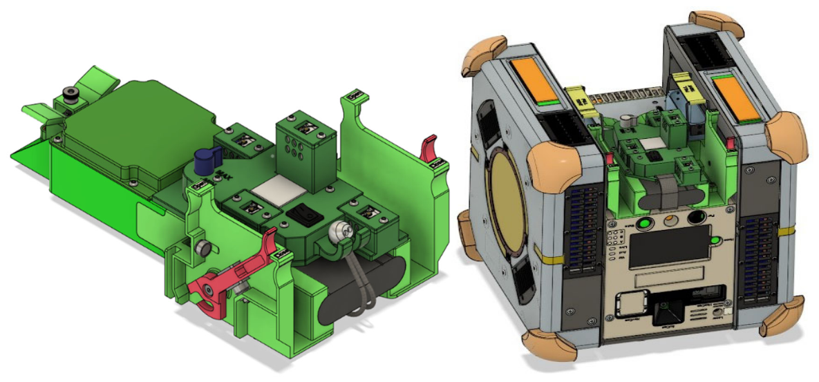
Figure 2.
The flight-qualified SVGS tetrahedral beacon (Revision 8) includes a DC-DC converter, LiPo battery, and overdischarge protection circuitry. A dimmer allows adjusting to different illumination conditions within the ISS environment.
Figure 2.
The flight-qualified SVGS tetrahedral beacon (Revision 8) includes a DC-DC converter, LiPo battery, and overdischarge protection circuitry. A dimmer allows adjusting to different illumination conditions within the ISS environment.
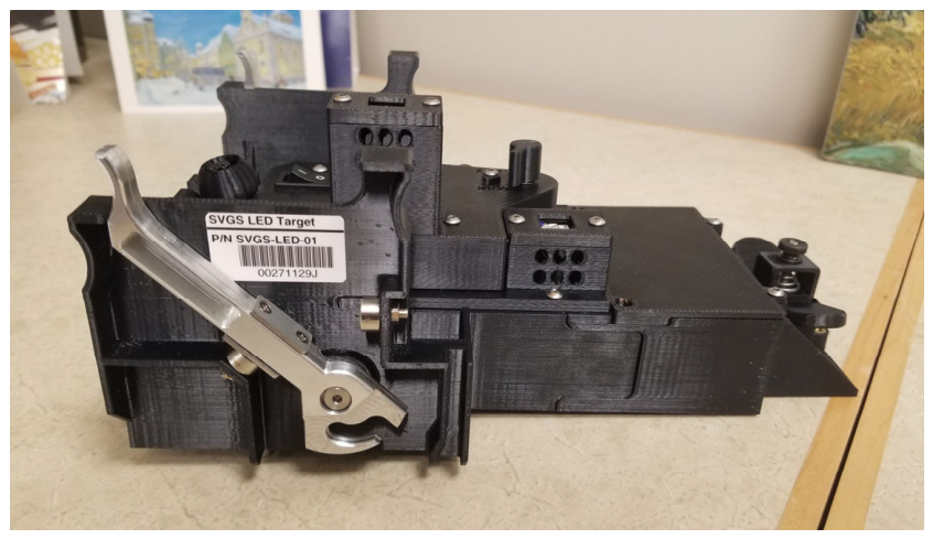
Figure 6.
SVGS Maneuver 2: Leader-follower maneuver: two Astrobee robots operate in formation flight using SVGS-based relative navigation. The leader executes a predefined trajectory relative to a fixed beacon, while the follower maintains a constant separation distance by tracking the leader’s motion. The accuracy of the follower’s motion depends on both its own estimation and the leader’s trajectory fidelity.
Figure 6.
SVGS Maneuver 2: Leader-follower maneuver: two Astrobee robots operate in formation flight using SVGS-based relative navigation. The leader executes a predefined trajectory relative to a fixed beacon, while the follower maintains a constant separation distance by tracking the leader’s motion. The accuracy of the follower’s motion depends on both its own estimation and the leader’s trajectory fidelity.
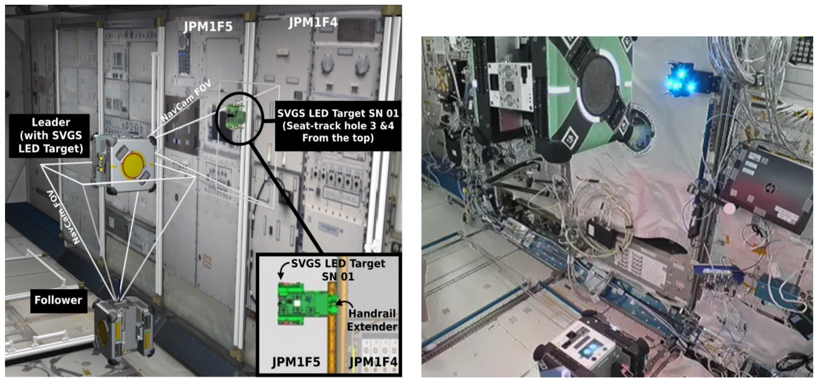
Figure 7.
Maneuver 2A and 2C, SVGS Science 1. XYZ robot coordinates vs. time: comparison between Astrobee metrology (solid traces) and SVGS position estimates (dotted traces). Motion commands are shown in green.
Figure 7.
Maneuver 2A and 2C, SVGS Science 1. XYZ robot coordinates vs. time: comparison between Astrobee metrology (solid traces) and SVGS position estimates (dotted traces). Motion commands are shown in green.
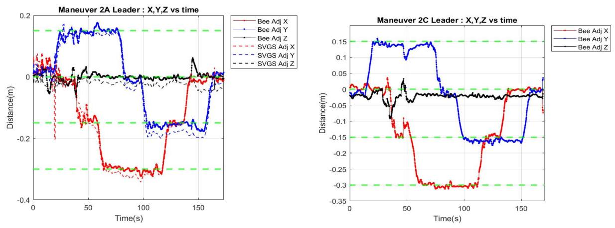
Figure 8.
Maneuver 2C, SVGS Science 1. (left) motion command (green trace) and corresponding XY robot position (red), (right) Astrobee Euler angles as function of time.
Figure 8.
Maneuver 2C, SVGS Science 1. (left) motion command (green trace) and corresponding XY robot position (red), (right) Astrobee Euler angles as function of time.
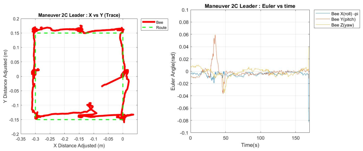
Figure 9.
Maneuver 2A, SVGS Science 1. (left) motion command (green trace) and corresponding XY robot position (red), SVGS data is shown in blue. Astrobee Euler angles as function of time.
Figure 9.
Maneuver 2A, SVGS Science 1. (left) motion command (green trace) and corresponding XY robot position (red), SVGS data is shown in blue. Astrobee Euler angles as function of time.
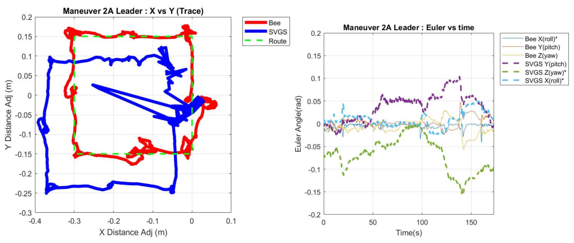
Figure 10.
Maneuver 2A (Queen) + 2F (Bumble), SVGS Science 2, Leader results. Results illustrate SVGS operation in real time to support formation flight. SVGS tracking closely follows Astrobee metrology with no significant drift: leader provides a reliable reference for the follower. (left) motion command (green trace) and corresponding XY robot position (red), SVGS position data is shown in blue. (right) Astrobee Euler angles. SVGS measurements are shown as dotted lines, Astrobee metrology as solid lines.
Figure 10.
Maneuver 2A (Queen) + 2F (Bumble), SVGS Science 2, Leader results. Results illustrate SVGS operation in real time to support formation flight. SVGS tracking closely follows Astrobee metrology with no significant drift: leader provides a reliable reference for the follower. (left) motion command (green trace) and corresponding XY robot position (red), SVGS position data is shown in blue. (right) Astrobee Euler angles. SVGS measurements are shown as dotted lines, Astrobee metrology as solid lines.
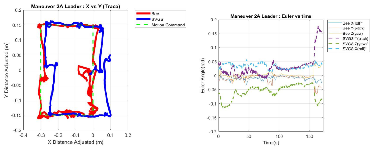
Figure 11.
Maneuver 2A (Queen) + 2F (Bumble) during SVGS Science 2: Follower and Leader formation flight. (left) leader’s motion command (green trace) and corresponding XY leader position (red), Follower position is shown in crimson. (right) Astrobee Euler angles as function of time, SVGS measurements shown as dotted lines and Astrobee metrology as solid lines. The estimation of Euler angles by Astrobee native metrology is significantly affected in the Follower due to partial blockage of the follower’s line of sight (LOS) caused by the leader proximity to the follower. This emphasizes the advantage of having an independent pose estimation method such as SVGS in proximity operations when native localization is map-based and partial blockage of LOS are likely.
Figure 11.
Maneuver 2A (Queen) + 2F (Bumble) during SVGS Science 2: Follower and Leader formation flight. (left) leader’s motion command (green trace) and corresponding XY leader position (red), Follower position is shown in crimson. (right) Astrobee Euler angles as function of time, SVGS measurements shown as dotted lines and Astrobee metrology as solid lines. The estimation of Euler angles by Astrobee native metrology is significantly affected in the Follower due to partial blockage of the follower’s line of sight (LOS) caused by the leader proximity to the follower. This emphasizes the advantage of having an independent pose estimation method such as SVGS in proximity operations when native localization is map-based and partial blockage of LOS are likely.
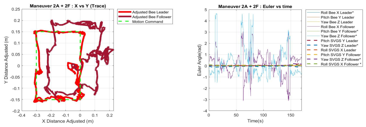
Figure 12.
Maneuver 2A (Queen) + 2F (Bumble) during SVGS Science 2. XYZ robot coordinate vs. time. Astrobee coordinates are shown in solid lines, both for Leader and Follower, SVGS coordinates are shown in dotted lines, illustrating delay in follower motion.
Figure 12.
Maneuver 2A (Queen) + 2F (Bumble) during SVGS Science 2. XYZ robot coordinate vs. time. Astrobee coordinates are shown in solid lines, both for Leader and Follower, SVGS coordinates are shown in dotted lines, illustrating delay in follower motion.
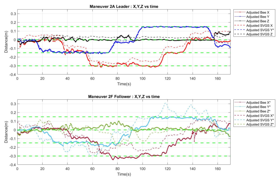
Figure 13.
Maneuver 2A (Queen) + 2F (Bumble), SVGS Science 2. Astrobee Euler angles vs. time. Astrobee coordinates are shown in solid lines, both for Leader and Follower, SVGS coordinates are shown in dotted lines. Astrobee estimates of roll and yaw based on native Astrobee metrology are significantly affected in the Follower due to partial blockage of line of sight by the Leader. SVGS estimation of Euler angles based on SVGS remains correct and is not affected by the Leader’s proximity.
Figure 13.
Maneuver 2A (Queen) + 2F (Bumble), SVGS Science 2. Astrobee Euler angles vs. time. Astrobee coordinates are shown in solid lines, both for Leader and Follower, SVGS coordinates are shown in dotted lines. Astrobee estimates of roll and yaw based on native Astrobee metrology are significantly affected in the Follower due to partial blockage of line of sight by the Leader. SVGS estimation of Euler angles based on SVGS remains correct and is not affected by the Leader’s proximity.
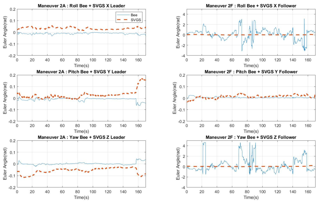
Figure 14.
(a). Maneuver 3: Multi-target path following maneuver. (left) maneuver configuration as the robot sequentially navigates between multiple SVGS targets on a vertical plane parallel to the ISS wall. The path includes transition points where SVGS must switch its visual reference from one beacon to the next. This requires robust target identification where more than one beacon shows in the image stream. (right) Exact spatial location of the SVGS beacons on the ISS JPM forward wall, where LED 1 and 4 are blue, LED 2 is red, and LED 3 is green.
Figure 14.
(a). Maneuver 3: Multi-target path following maneuver. (left) maneuver configuration as the robot sequentially navigates between multiple SVGS targets on a vertical plane parallel to the ISS wall. The path includes transition points where SVGS must switch its visual reference from one beacon to the next. This requires robust target identification where more than one beacon shows in the image stream. (right) Exact spatial location of the SVGS beacons on the ISS JPM forward wall, where LED 1 and 4 are blue, LED 2 is red, and LED 3 is green.
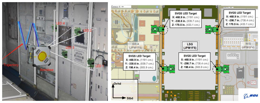
Figure 15.
(a). Hardware-in-the-loop (HIL) simulation of maneuver 3A using Gazebo and an Inforce 6640SBC single board computer. (b) Maneuver 3A, during SVGS Science 3. XYZ robot coordinate vs. time are shown in solid trace (red, blue, black) while the corresponding SVGS readings are shown in dotted lines. The changes in color of interest are shown as vertical green traces. Close agreement between the HIL simulation and experimental data is shown throughout the maneuver.
Figure 15.
(a). Hardware-in-the-loop (HIL) simulation of maneuver 3A using Gazebo and an Inforce 6640SBC single board computer. (b) Maneuver 3A, during SVGS Science 3. XYZ robot coordinate vs. time are shown in solid trace (red, blue, black) while the corresponding SVGS readings are shown in dotted lines. The changes in color of interest are shown as vertical green traces. Close agreement between the HIL simulation and experimental data is shown throughout the maneuver.
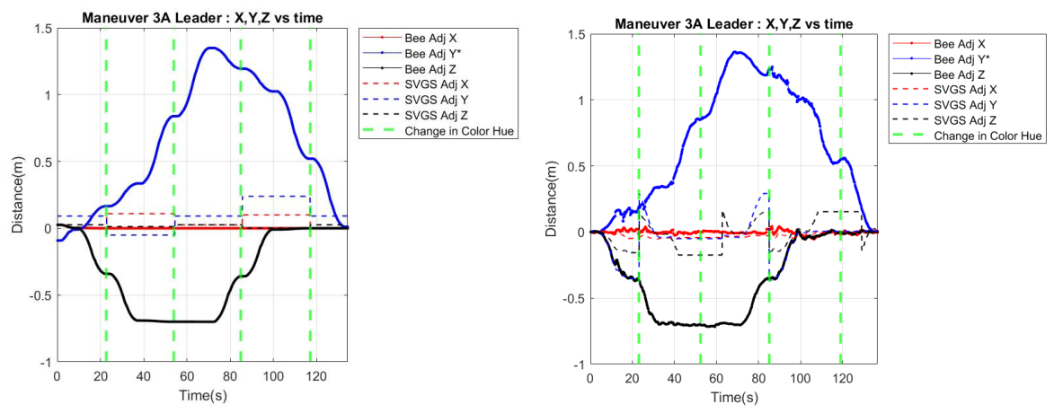
Figure 19.
(right) Maneuver 4: Multi-target Leader-Follower maneuver. The Leader navigates relative to a set of SVGS targets of different colors (Maneuver 3 sequence) while the Follower follows the leader based on SVGS measurements. This configuration serves as a precursor to more complex formation flight maneuvers. (left) Maneuver 4A results, SVGS Science 4. Follower robot coordinates (XYZ vs. time) are shown in solid trace (red, blue, black) while the corresponding SVGS readings are shown in dotted lines. Plot illustrates a breakdown in the native Astrobee Follower localization due to partial block of line of sight caused by Leader proximity, showing the impact of poor feature availability and occlusions on localization and navigation performance.
Figure 19.
(right) Maneuver 4: Multi-target Leader-Follower maneuver. The Leader navigates relative to a set of SVGS targets of different colors (Maneuver 3 sequence) while the Follower follows the leader based on SVGS measurements. This configuration serves as a precursor to more complex formation flight maneuvers. (left) Maneuver 4A results, SVGS Science 4. Follower robot coordinates (XYZ vs. time) are shown in solid trace (red, blue, black) while the corresponding SVGS readings are shown in dotted lines. Plot illustrates a breakdown in the native Astrobee Follower localization due to partial block of line of sight caused by Leader proximity, showing the impact of poor feature availability and occlusions on localization and navigation performance.
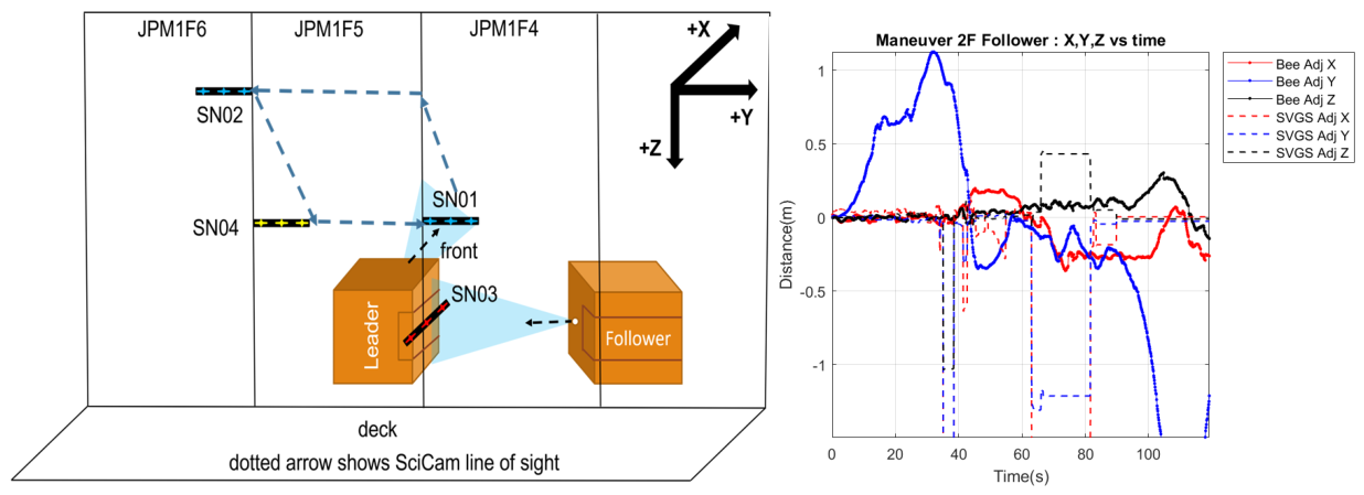
Figure 20.
3DOF gantry for Astrobee HIL Simulation. Stepper motors for each axis are controlled by a ROS node on an external Arduino board, connected to the simulation computer via USB.
Figure 20.
3DOF gantry for Astrobee HIL Simulation. Stepper motors for each axis are controlled by a ROS node on an external Arduino board, connected to the simulation computer via USB.
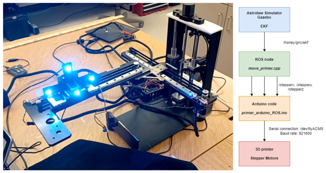
Figure 21.
Hardware in the loop (HIL) simulation of the Follower motion code (MoveUVGS). The Follower Astrobee generates motion commands based on UVGS 6-DOF pose vectors. The HIL demonstration uses an Intel D455 camera to locate the SVGS beacon (bottom, left) and uses the detected blobs (top, left) to calculate UVGS-2 6-DOF output. The demonstration is based on moving the camera on a square trajectory in front of the beacon, which creates motion commands in NASA’s Gazebo simulation environment, demonstrating follower behavior on Astrobee.
Figure 21.
Hardware in the loop (HIL) simulation of the Follower motion code (MoveUVGS). The Follower Astrobee generates motion commands based on UVGS 6-DOF pose vectors. The HIL demonstration uses an Intel D455 camera to locate the SVGS beacon (bottom, left) and uses the detected blobs (top, left) to calculate UVGS-2 6-DOF output. The demonstration is based on moving the camera on a square trajectory in front of the beacon, which creates motion commands in NASA’s Gazebo simulation environment, demonstrating follower behavior on Astrobee.
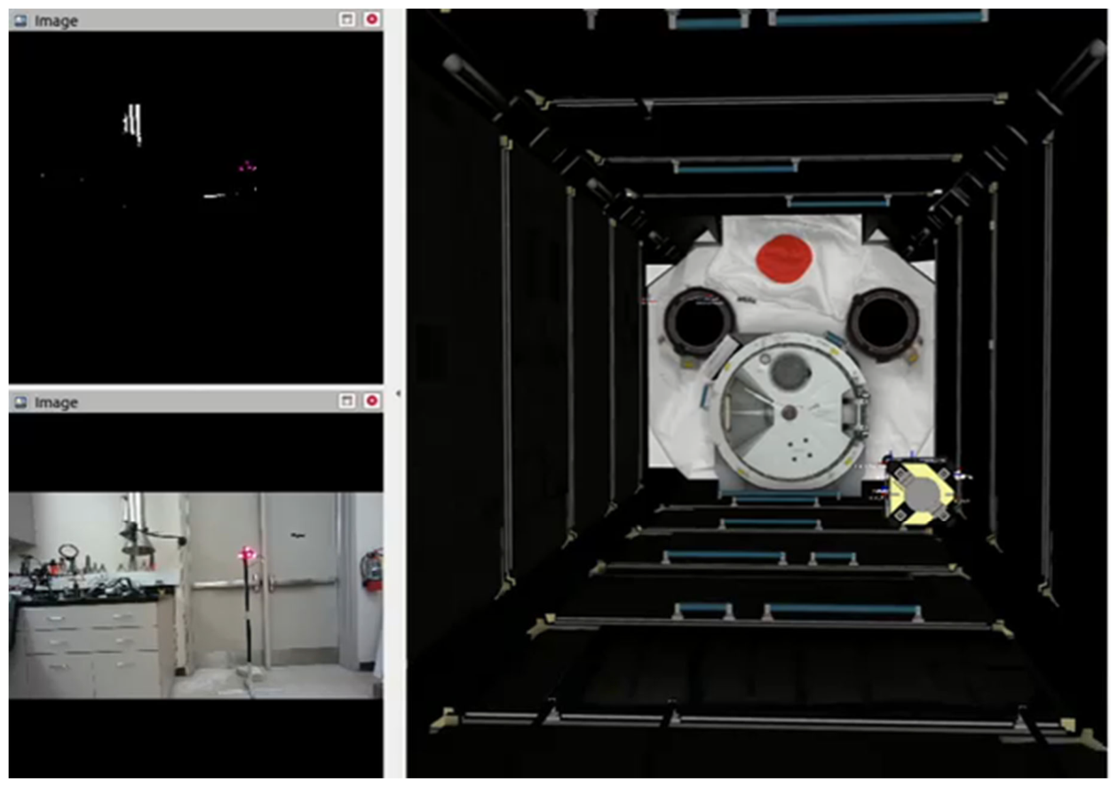
Figure 22.
GT1 experiment at NASA Ames’ Granite Lab. (left): layout of the experiment, (right, top): NavCam image sample, (right, bottom): post-processed image on RVIZ showing correct identification of the four beacon blobs as red dot overlays.
Figure 22.
GT1 experiment at NASA Ames’ Granite Lab. (left): layout of the experiment, (right, top): NavCam image sample, (right, bottom): post-processed image on RVIZ showing correct identification of the four beacon blobs as red dot overlays.
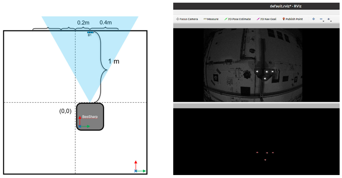
Figure 23.
GT2 Experiment: Demonstration of UVGS-AstroLoc Fusion via AR Pipeline. (left): outline of Astrobee home position at Granite Lab for GT2. (right) Astrobee position after two repetitions of a square maneuver. The red trace shows motion performance using the native Map Landmark pipeline (ML), the blue trace shows motion performance using uVGS-ML sensor fusion.
Figure 23.
GT2 Experiment: Demonstration of UVGS-AstroLoc Fusion via AR Pipeline. (left): outline of Astrobee home position at Granite Lab for GT2. (right) Astrobee position after two repetitions of a square maneuver. The red trace shows motion performance using the native Map Landmark pipeline (ML), the blue trace shows motion performance using uVGS-ML sensor fusion.
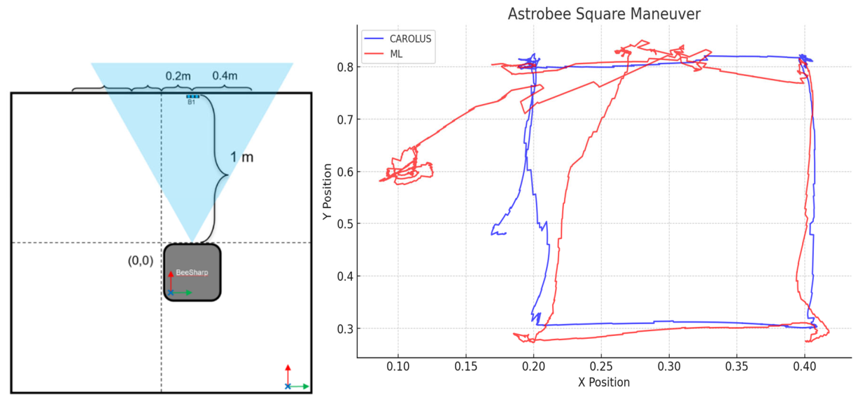
Figure 24.
(Left): GT3 Experiment: Leader maneuver using uVGS-AstroLoc Fusion and color camera (SciCam image stream). (Right): GT4 Experiment: outline of Leader-Follower maneuver at Ames’ Granite Lab. The starting Home position is shown.
Figure 24.
(Left): GT3 Experiment: Leader maneuver using uVGS-AstroLoc Fusion and color camera (SciCam image stream). (Right): GT4 Experiment: outline of Leader-Follower maneuver at Ames’ Granite Lab. The starting Home position is shown.
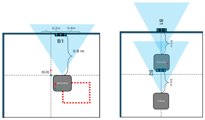
Figure 25.
GT3 Experiment results. Leader maneuver with UVGS-AstroLoc fusion. (Left) 30-cm per side square maneuver using a sequence of manual GDS commands. (Right) 30-cm per side square maneuver using a Leader motion script. A ~ 20 mm tilt in the vertical direction (in both cases) is attributed to uneven horizontal alignment of Astrobee with its air bearing support.
Figure 25.
GT3 Experiment results. Leader maneuver with UVGS-AstroLoc fusion. (Left) 30-cm per side square maneuver using a sequence of manual GDS commands. (Right) 30-cm per side square maneuver using a Leader motion script. A ~ 20 mm tilt in the vertical direction (in both cases) is attributed to uneven horizontal alignment of Astrobee with its air bearing support.
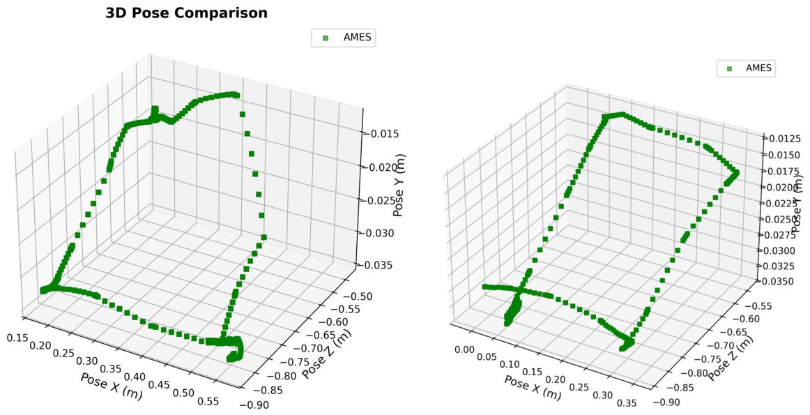
Figure 26.
GT4 Experiment results: Leader-Follower maneuver at Ames’ Granite Lab. (Left) Leader motion: 30 cm per side square maneuver using UVGS-AstroLoc sensor fusion. (Right) Leader (green trace) and Follower (blue trace) trajectories in the XY plane.
Figure 26.
GT4 Experiment results: Leader-Follower maneuver at Ames’ Granite Lab. (Left) Leader motion: 30 cm per side square maneuver using UVGS-AstroLoc sensor fusion. (Right) Leader (green trace) and Follower (blue trace) trajectories in the XY plane.
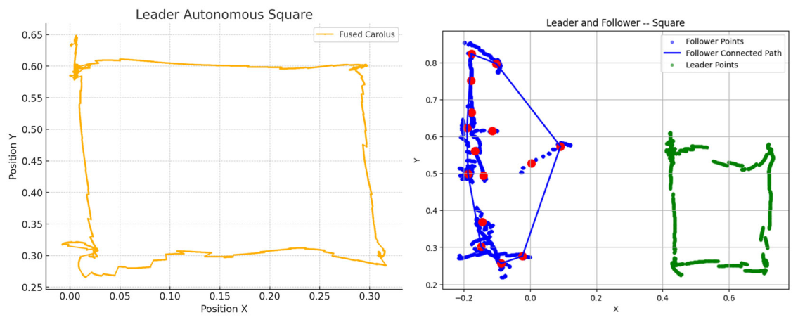
Disclaimer/Publisher’s Note: The statements, opinions and data contained in all publications are solely those of the individual author(s) and contributor(s) and not of MDPI and/or the editor(s). MDPI and/or the editor(s) disclaim responsibility for any injury to people or property resulting from any ideas, methods, instructions or products referred to in the content. |
© 2026 by the authors. Licensee MDPI, Basel, Switzerland. This article is an open access article distributed under the terms and conditions of the Creative Commons Attribution (CC BY) license (http://creativecommons.org/licenses/by/4.0/).
Copyright: This open access article is published under a Creative Commons CC BY 4.0 license, which permit the free download, distribution, and reuse, provided that the author and preprint are cited in any reuse.