

Submitted:
15 May 2026
Posted:
18 May 2026
You are already at the latest version
Abstract
This article considers several aspects of creating a combined bioreactor heating system without the use of external power grid power sources. It's known to intensify anaerobic digestion of organic waste, the bioreactor temperature is maintained within a specified range. A bioreactor heating system based on a "water jacket" , that heated by combustion of coal-water fuel has been developed. A technology for preparing and burning coal-water fuel using a radial circulation injection device is offered. Calculations are performed to determine the optimal temperature regime for the combustion process. The results obtained can contribute to the optimization of waste management technologies and ensure environmental sustainability by reducing carbon dioxide emissions and waste accumulation.
Keywords:
biogas
; bioreactor
; water jacket
; coal‐water fuel
; injection
; combustion efficiency
; combustion energy efficiency
1. Introduction
In the current conditions of global climate change and depletion of natural resources, biogas production through the processing of various waste can contribute to energy security and environmental sustainability. Biogas, an environmentally friendly energy source, is a product of anaerobic decomposition of organic waste and is used to generate heat and electricity [1,2]. The main sources of biogas include waste from processing and food industries, agricultural and livestock farms. Also, in [3] a multi-energy system with biogas, solar energy and a phased storage tank is presented, as well as the optimization of its operation. The processing of such materials not only helps to reduce the volume of waste in landfills, but also reduces greenhouse gas emissions, helping to ensure environmental standards [4,5,6]. Let us provide brief information on the types and characteristics of small- and medium-capacity bioreactors. The design of a home-made bioreactor designed for processing horse manure in rural and agricultural settings is presented in [7]. However, this study is limited to examining only one type of feedstock and does not include an analysis of the possibility of processing other organic waste and materials. [8] demonstrates the successful application of anaerobic co-digestion of catering waste using partially pre-treated corn residues for the production of biogas and biofertilizers. There are examined the potential of using biogas plants with heating of fermented biomass using renewable energy sources on small-scale consumer farms [8]. A solar system for thermal treatment of municipal solid waste is proposed and a methodology for the technical and economic analysis of solar-powered municipal solid waste treatment systems is presented [9,10].
Despite numerous factors contributing to the successful implementation of various devices, biogas production has not yet become widespread, not only in Kazakhstan. One reason is that continuous biowaste fermentation requires maintaining a specific temperature in the bioreactor. Heating the biowaste tank requires additional expenses, which increases the cost of production. Often, the costs of biofuel production exceed the revenue from its sale. This article discusses some aspects of creating a combined bioreactor heating system without the use of external power grid power sources. The bioreactor’s thermal regime will be maintained by heating the water jacket using a liquid coal-water fuel (CWF). Liquid (CWF) was chosen because it is prepared using a widely available and relatively inexpensive low-grade coal mined in open pit mines. Coal samples for the study were taken from the Shubarkul deposit in central Kazakhstan.
2. Materials and Methods
2.1. Technology of Coal-Water Fuel Preparation Using the Electrical Impulse Method
To prepare a coal-water mixture, large pieces of coal must be crushed to millimeter-sized fractions. Uniform coal particle sizes are achieved by mechanical crushing followed by electrohydraulic action [11,12,13,14,15,16,17]. According to the proposed method, coal and coal slurry are ground to a fine coal powder. The design and operating principle of the installation implementing this method are described in detail in [15].
Applying an electrical pulse to the process medium produces a coal-water suspension with the required particle size distribution (50–250 µm). The specific energy supplied to the working electrode varies from 0.75×10⁴ J/m² to 2.25×10⁴ J/m², allowing for the study of the system’s efficiency in producing the required coal-water suspension. Pre-treated coal (particle size 10–15 mm) enters the mill drum through a loading sleeve, where three positive and negative electrodes simultaneously act as a mixer. When the unit is turned on, an electrical discharge is generated between the positive and negative electrodes at a specific frequency, thereby grinding the coal.
It was found that with increasing specific energy, the diameter of the crushed coal particles decreases from 250 µm to 50 µm, allowing for the production of the required suspension. However, coal particles with a diameter of less than 20 µm are carried away by the liquid flow. Based on the conducted research, a frequency range was determined. The most effective method for grinding coal and slurry is an electrical pulse in a liquid medium with a pulse rate of 300–420. The application of an electrical pulse to the process medium allows for the production of a coal-water suspension with the required particle size distribution (50–250 µm). A device was developed in which the specific energy supplied to the working electrode varies from 0.75 × 10⁴ J/m² to 2.25 × 10⁴ J/m², allowing for the production of the required coal-water suspension.
The influence of the shape of the negative electrode in the working cell on the grinding process was studied for the first time. The negative electrode in the grinding device was the inner surface of a cylindrical metal body (diameter d = 70 mm, height H = 150 mm), and the positive electrode was a carbon steel rod with a diameter of 5 mm, insulated with nylon grade 30HGSA.
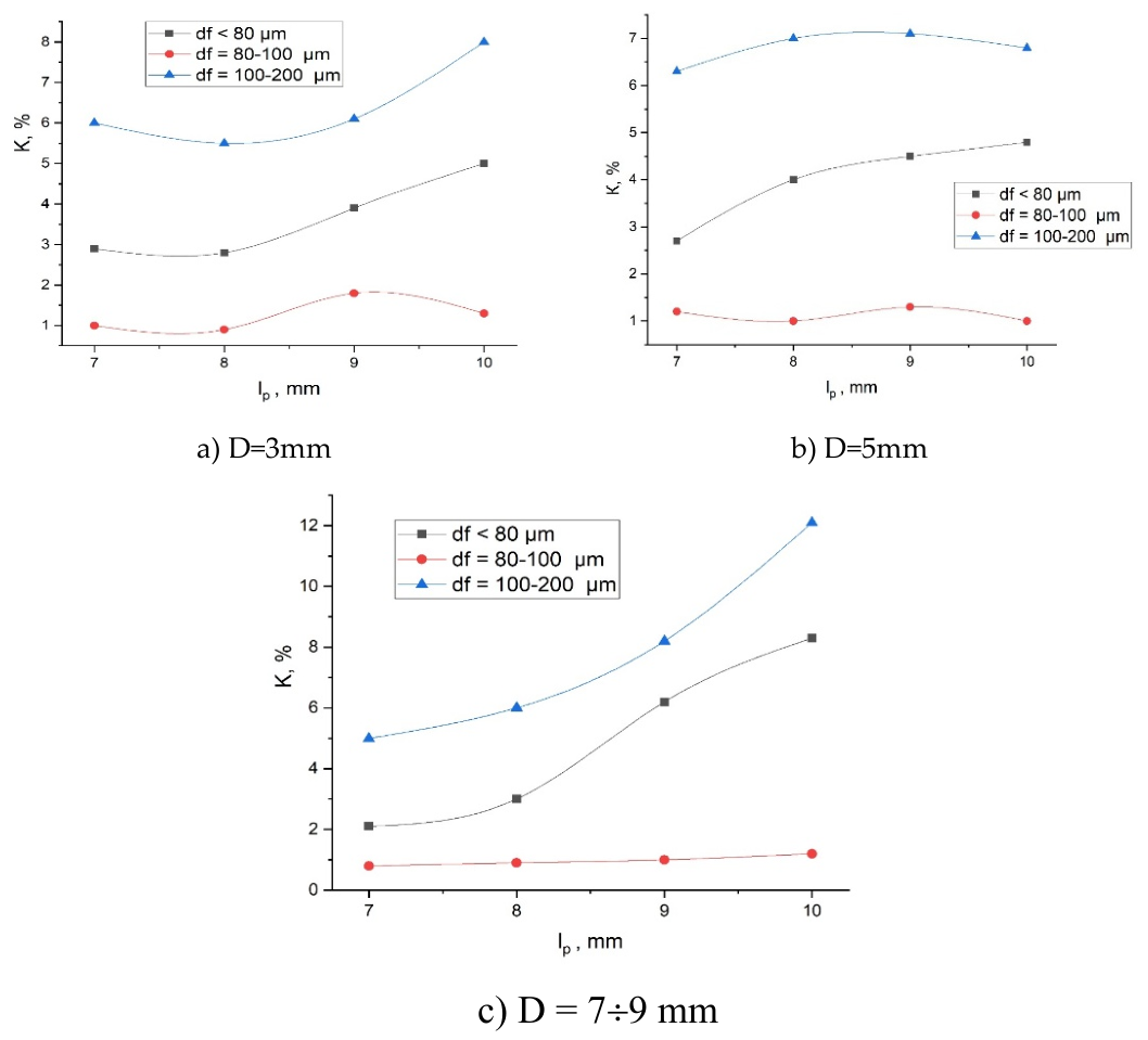
Experiments were conducted to study the dependence of the coal crushing process on the distance between electrodes, which varied from 7 to 9 mm [16]. At a distance between electrodes of 7 mm, the voltage measured by a kilovoltmeter was 17 kV, at 8 mm – 23 kV, and at 9 mm – 28 kV. Based on these results, graphs of the crushing process depending on changes in the distance between electrodes were constructed (Figure 2). The particle diameters (D) fed to the primary crusher varied on average from 3 mm to 9 mm.
The energy consumption and crusher parameters were determined to produce coal particles of the specified diameter required for the preparation of liquid coal fuel. These graphs show that increasing the interelectrode distance lp and, consequently, increasing the electrical pulse energy increases the grinding efficiency. Experiments have shown that with an interelectrode distance lp = 10 mm and a capacitor bank capacitance of 0.75 μF, the operating voltage is 30 kV. The content of fine fractions with a maximum diameter of d < 80 μm is 9%. Smaller fractions settle to the bottom of the cell, so the impact force on the cell bottom is minimal. To obtain CWF, carbon powder (60%) ground to a given dispersion is mixed with water (40%), i.e., in a ratio of 3/4.
Figure 1.
Dependence of grinding processes on the interelectrode distance.
In addition, studies using the JSPM-5400 atomic force microscope (AFM, JEOL, Japan) in University Scientific Research Center “Alternative Energy laboratory were conducted. Using this microscope, it was possible to obtain three-dimensional images of the coal surface structure before and after electro-impulse treatment. Figure 2 shows the structure of the Shubarkul deposit’s coal surface before and after treatment. The coal surface before electrohydraulic treatment has a relatively smooth structure (Figure 2a), however, individual depressions and dents are observed. Figure 2 (b) shows the structure of the coal surface after treatment at a magnification of 5000 nm.
Figure 3 presents the structure of the coal surface after electrohydroimpulse treatment of the fractions with a diameter of df=140 μm (a magnification of 10 nm). Under the influence of electrohydraulic phenomena and shock waves, the structure of the coal surface undergoes significant changes. It was found that fractures and cracks were present in the coal fractions before treatment. After electrohydroimpulse processing, the size of the fractures and cracks increases, leading to the crushing and grinding of the coal fractions.
The images of the coal surface treated by electrohydraulic action demonstrate an increase in surface irregularities compared to the untreated coal surface, as well as the formation of a large number of sharp peaks and edges. The formation of such sharp features indicates the separation of the material into microregions. In our opinion, the appearance of sharp peaks on the coal surface after treatment may enhance the interaction with plasticizers during the production of liquid fuels.
2.3. Coal-Water Fuel Combustion Technology Using a Radial Circulation Injector
In practice, a combination of two types of mechanical and pneumatic nozzles is used to inject the coal-water slurry into the combustion chamber. Initial atomization occurs in the mechanical nozzle, and then the coal-water fuel is injected into the combustion chamber through holes under compressed air pressure. Efficient mixing of the three-phase coal-water fuel mixture with the oxidizer can be achieved using a vortex feed. For this purpose, it is necessary to use a nozzle with a profile that ensures the creation of a uniform velocity field. The most suitable for this purpose is the Vitoshinsky nozzle, which provides better flow uniformity compared to conical or radial nozzles [18,19]. Figure 4 shows the longitudinal profile of a nozzle with an internal channel formed by profile rotation. The nozzle shape, which ensures a smooth narrowing of the flow, is calculated using a special geometric law - the Vitoshinsky formula:
where , ; - nozzle inlet radius; - nozzle outlet radius; - nozzle length; - current coordinates of points lying on the generatrix, starting from the nozzle inlet.
The Vitoshinsky nozzle [19] is a profiled channel with a unique law of cross-sectional area variation, ensuring the efficient conversion of gas thermal energy into kinetic energy of a directed flow. The nozzle’s design ensures the formation of a laminar flow core with a jet angle of approximately 12° for air, making it particularly useful for research in aerodynamics and gas dynamics. Figure 5 shows photographs of a nozzle with a tangential swirl design for atomizing coal-water fuel.
The resulting chemical combustion reactions lead to increased turbulence, which increases the reaction intensity due to the increased mixing rate of the fuel and oxidizer.
2.3. Modeling the Combustion Process of Coal-Water Fuel
To ensure that the use of a tangentially swirling nozzle for spraying coal-water fuel actually contributes to an increase in the intensity of combustion reactions, calculations were performed in the Ansys Fluent package. The simulation was conducted by calculating the convective terms of the equation using a second-order spatially accurate fuzzy system [20]. The thermophysical properties of air were calculated in accordance with their polynomial dependence on temperature. In the obtained images of the velocity and temperature distribution fields across the burner volume, the formation of a high-velocity zone was detected in the upper regions of the burner and to the left of the nozzle. This is explained by the fact that the CWF swirls under the action of the air flow pressure when passing through the nozzle, and the velocity of the mixture increases near the upper boundary of the burner.
The graphs show that there are two regions with lower temperatures. This is explained by the fact that the burner has two openings through which air is supplied, the initial temperature of which is lower. The minimum temperature is observed in the area of the nozzle, and the maximum is in the center of the burner. Calculations show that vortex injection of the CWF increases the retention time of burning particles in the combustion chamber, which has a beneficial effect on reducing ash deposits and harmful volatile substances.
Calculations in the SOLIDWORKS software package allowed us to obtain temperature and velocity distribution patterns in various burner cross-sections, determining the trajectory of fuel particles in a vortex burner. Figure 6 shows the temperature field for the mass evaporation rate of the liquid phase in a hydrocarbon fuel droplet. In this case, the following boundary conditions were adopted:
When air is supplied through the pump: temperature – 300 K, diameter – 4 mm, gas velocity – 50 m/s.
When air is supplied through the purge channel: gas velocity – 25 m/s, temperature – 300 K, turbulence level – 0.1.
To create ignition conditions, it is necessary to inject the CWF simultaneously with compressed air at a volume of 20% of the mixture volume, heated to 300-500 °C. With continuous fuel supply to the vortex burner, the temperature gradually reaches 1143 °C, resulting in a steady-state combustion process. During water evaporation, process stability is maintained for a significant period due to the increased temperature of the solid phase of the CWF droplets. Computer analysis of the burner temperature regime based on calculated furnace dependencies showed that a temperature in the range of 700-1200 °C ensures optimal CWF combustion. Simulation of the CWF combustion process under vortex injection conditions into the combustion chamber allowed us to determine the most optimal combustion regime.
3. Results and Discussion
3.1. Design of a Burner Device with a Vortex Swirl of Atomization of Coal-Water Fuel
Figure 7 shows the basic diagram of the experimental device for combustion of CWF. The device consists of the following parts: a compressor, a nozzle, a cell, and a burner. The operating principle is as follows: water-carbon fuel is supplied to the cell, the cell lid is tightly closed, the combustion chamber is heated to a predetermined temperature using a burner, and the temperature is measured. In [20] it is shown that heating with diesel fuel reached 650 °C within 20 minutes, and then heating of diesel fuel and water-water fuel continued for 2 minutes up to a temperature of 800 °C. After the supply of diesel fuel is stopped, the combustion temperature of the hydrocarbon fuel gradually decreases.
A guide fan is used to regulate the air flow. A nozzle is located in the air duct, delivering air directly to the swirl burner. Effective mixing ensures more complete combustion, reduces harmful emissions, and stabilizes the combustion process. Periodically, after 5-10 days of operation, it is necessary to clean the swirl channel and nozzle openings, as ash entering them can cause temperature fluctuations. Combustion of CWF in a swirl burner produces ash with a particle size of approximately 0.16-0.35 mm. The combustible ash content does not exceed 4-5%. The ash is light brown and porous; its bulk density is 200-360 kg/m³. The ash is collected in a hopper and transported to a mobile container. Due to its physical and technical properties, the resulting ash can be used in road construction.
Figure 8 shows a photograph of a burner combusting vacuum fuel atomized with a swirl-forming nozzle using a cylindrical, radially rotating nozzle. In the experiments, the vacuum fuel was first heated to 600 °C using diesel fuel. The vacuum fuel, heated in the injector, was then injected through the nozzle cells under compressed air pressure into the combustion chamber, where the temperature increased to 750 °C. The diesel fuel supply was then stopped, and spontaneous combustion of the vacuum fuel occurred. The combustion process lasted up to 30 minutes.
The tests confirmed the effectiveness of the Vitoshinsky profile nozzle, as it provides a smooth narrowing with swirling flow and more efficient atomization of the mixture after exiting the nozzle. The smooth self-organization of the swirling flow prevents clogging at the nozzle mouth. The developed CWF incineration unit can be used to heat a bioreactor using a special water jacket.
3.2. Bioreactor Configuration and Operating Principle
Bioreactors are currently being developed for the processing of organic waste using renewable energy sources [3,5,21,22,23,24,25]. Renewable energy sources such as wind turbines, solar collectors, and geothermal energy sources are used to maintain the temperature regime of the bioreactor. Disadvantages of the proposed devices include complex design, high equipment cost, limited mobility, strong dependence on weather conditions, and others. To overcome these shortcomings, it is proposed to use a system with a radially rotating nozzle for CWF combustion.
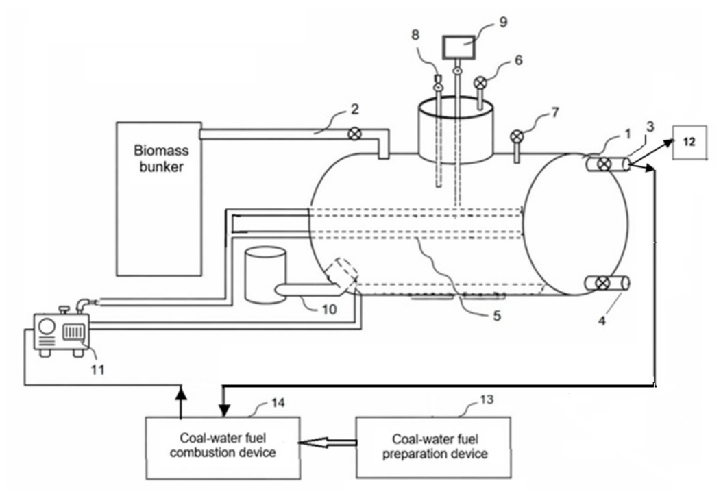
The bioreactor for processing organic waste discussed in this article consists of a cylindrical body, pipes for loading, unloading, and draining, a bubbling channel, heating elements, a pressure gauge, a thermometer, and a mechanical stirrer connected to a gearbox. The temperature inside the bioreactor must be maintained at 40-45 °C, and the mixture must be regularly stirred. The sparging channel is located at the bottom of the bioreactor body, where the heating elements are also located. The most effective solution for maintaining the bioreactor’s thermal conditions is the use of a so-called water jacket (thermal jacket), consisting of parallel pipes surrounding the bioreactor body (Figure 9).
Water circulating in the pipes (the heat transfer fluid) is initially heated by burning a water-soluble fuel in a specially designed device with a radially rotating nozzle. Then, after reaching a steady-state mode for processing biowaste (anaerobic digestion), the biogas generated directly in the bioreactor can be used as fuel.
An automated control system (8) monitors operating modes and regulates heat sources depending on the time of day and weather conditions. A dedicated automatic switch ensures continuous biogas production. Biogas extracted from the bioreactor is purified of impurities using a filter with a water seal (11) and then fed to the gas holder via a low-flow compressor, and partially to the CWF combustion unit. This ensures stable biogas production. The biogas collected in the gas holder is then supplied to special cylinder units (12) via a compressor to consumers, where it can be converted into heat or electricity.
Filling a 3 m³ bioreactor 2/3 full with beef manure mixed with water allows for the production of up to 24 m³ of biogas per day. Tests have shown that (23-25) % of the total gas produced is consumed for heating the bioreactor. The remaining (77-75) % is used for heating the room or for filling gas cylinders after compression. It should be noted that the waste can be used to produce organic fertilizer. Thus, the bioreactor’s thermal conditions can be maintained regardless of weather conditions, i.e., despite the lack of wind or solar radiation on cloudy or rainy days.
4. Conclusion
This article examines several challenging aspects of developing a combined bioreactor heating system using coal-water fuel for intensifying the anaerobic digestion of organic waste in the bioreactor. The choice of coal-water fuel is justified by the large reserves of readily available and relatively inexpensive low-grade coal mined at the Shubarkul mine in central Kazakhstan using an open-pit method. A brief description of the coal-water fuel preparation system and the technology using electric pulse treatment are provided. Changes in the surface structure of coal particles before and after treatment are demonstrated. A method for injecting coal-water fuel into the combustion chamber using a special vortex nozzle is developed. Calculation results for determining the optimal combustion temperature are presented.
Based on the tests conducted, a bioreactor heating system was developed that operates continuously within a specified temperature range, regardless of weather conditions. The results obtained can contribute to the optimization of biotechnologies in waste management and the reduction of accumulated waste. However, in order to ensure environmental sustainability and minimize carbon dioxide emissions in the future, it is planned to create a sustainable heating system for the bioreactor entirely using alternative energy sources.
Author Contributions
Sakipova Saule: conceptualization, supervision; Smagulov Zhanaidar: funding acquisition; investigation; Nussupbekov Bekbolat: methodology, writing—review and editing; Ismailov Zharas: formal analysis, visualization; Duisenbayeva Moldir: software, writing—original draft; Nussupbekov Ulan, Turlybekova R.: data curation, validation. All authors have read and agreed to the published version of the manuscript.
Funding
This research was funded by a grant from the Science Committee of the Ministry of Science and Higher Education of the Republic of Kazakhstan (AP26102107) “Development and creation of an autonomous installation that provides heat and electricity to industrial and residential buildings without using traditional energy resources”.
Data Availability Statement
The original contributions presented in the study are included in the article; further inquiries can be directed to the corresponding author.
Acknowledgments
The authors would like to acknowledge the use of ChatGPT (OpenAI) for assistance with wording and grammar in this manuscript.
Conflicts of Interest
The authors declare no conflicts of interest.
References
- Liu, Z.; Gao, X.; Li, Z.; Yang, X.; Hu, Y. (2023) Evaluation of Biogas and Solar Energy Coupling on Phase-Change Energy-Storage Heating Systems: Optimization of Supply and Demand Coordination. Buildings, 13, 2712. [CrossRef]
- Şenol, H., Erşan, M., & Görgün, E. (2020). Biogas production from the co-digestion of urban solid waste and cattle manure. European Journal of Science and Technology, Special Issue, 396-403. [CrossRef]
- Sharipov, M., Majitov, J., Imomov, S., Kovalev, I., Narzullayev, M., B., N., & Ziyoyev, D. (2026). Optimization of thermal processes in solar biogas plant. Eurasian phys. tech. j., 23(1 (55), 48–59. [CrossRef]
- Aji Mike Uche1, Ogbomida Temiotan Emmanuel, Onochie Uche Paul, Akingba Olawale, Kubeyinje Bawo Frank, Orerom Owomwan Rita, and Ogbonmwan Sundoiday Martin. (2020). Design and Construction of a Fixed Dome Biogas Plant for Biogas Production Using Cow Manure and Water Hyacinth. Afr. J. Environ. Sci. Technol., 14(1), 15–25. Article Number: DE9738662550. [CrossRef]
- Duisenbayeva, M., Schrager, E.R., Sakipova, S.E., & Nussupbekov, B.R. (2025). Study of optimal energy parameters of electro-hydropulse treatment for efficient extraction of variable from organic waste. Eurasian phys. tech. j., 22(2 (52), 54–59. [CrossRef]
- Akzamov S.S., Uzakov R., Davkaraliev E.A. (2021) Prospects for the Production and Use of Biogas Energy Today. Modern Scientific Research and Innovations. No. 1. https://web.snauka.ru/ Issues/2021/01/94276.
- Design, Monitoring, and Application of a Cost-Effective Bioreactor for Biogas Production Angela Ventura-Prados 1 Javier Sol’ıs-Garc’ıa. February 2025. [CrossRef]
- Anjum M, Qadeer S and Khalid A (2018) Anaerobic Co-digestion of Catering and Agro-Industrial Waste: A Step Forward Toward Waste Biorefinery. Front. Energy Res. 6:116. [CrossRef]
- Liu, Z.; Gao, X.; Li, Z.; Yang, X.; Hu, Y. Evaluation of Biogas and Solar Energy Coupling on Phase-Change Energy-Storage Heating Systems: Optimization of Supply and Demand Coordination. Buildings 2023, 13, 2712. [CrossRef]
- Bobir Toshmamatov, Khayrullo Davlonov, Obid Rakhmatov and Abdumalik Toshboev. Recycling of municipal solid waste using solar energy. IOP Conf. Series: Materials Science and Engineering. 1030 (2021) 012165. [CrossRef]
- Atal A. and Levendis Y.A. (1993). Observations on the combustion behavior of coal water fuels and coal water fuels impregnated with calcium magnesium acetate. Combustion and Flame, 93(1-2):61–89. [CrossRef]
- Staroń A., Kowalski Z., Staroń P., and Banach M. (2016). Analysis of the useable properties of coal-water fuel modified with chemical compounds. Fuel Processing Technology, 152:183–191. [CrossRef]
- Rizun A.R., Denisyuk T.D., Golen Y.V., Kononov V.Y. & Rachkov A.N. (2011). Electric discharge disintegration and coal desulphurization in the manufacture of water-coal fuel. Surface Engineering and Applied Electrochemistry, 47(1):100–102. 2011. [CrossRef]
- Kondrat O., Shumilin T. (2023) Electrohydraulic Yutkin effect and electrospark discharges in liquids. Prospect. Dev. Oil Gas Fields. 3, 61–67. doi:. [CrossRef]
- Nussupbekov B., Khassenov A., Nussupbekov U., Akhmadiyev B., Karabekova D., Kutum B., Tanasheva N. (2022). Development of technology for obtaining coal-water fuel. Eastern-European Journal of Enterprise Technologies, 3, 8(117), 39–46. [CrossRef]
- Khassenov, A.; Karabekova, D.; Bolatbekova, M.; Nussupbekov, B.; Kissabekova, P.; Orazbayev, R. Development of an Electric Pulse Device for Coal Grinding. Appl. Sci. 2025, 15, 5548. [CrossRef]
- Kijo-Kleczkowska A. (2012). Research on coal-water fuel combustion in a circulating fluidized bed. Archives of Mining Sciences, 57(1):79–92. [CrossRef]
- Lavrukhin G.N. Aerogasdynamics of jet nozzles. Part 1. Internal characteristics of nozzles. Moscow, Science, 2003, 376 p. [in Russian] Available at: https://dokumen.pub/5922100130.html.
- Kabardin I.K., Rotar A.D., Meledin V.G., Zubanov K.S. (2025). Study of velocity distribution from vitoshinsky nozzle by laser doppler anemometry method. Interexpo GEO-Siberia, 8, 88-95. [CrossRef]
- Tanasheva N.K., Minkov L.L., Tleubergenova A.Zh., Sadenova K.K. (2019). Calculation of coal-water fuel combustion technology based on mathematical modeling. Bulletin of the Karaganda University. Physics Series. 3, 75, 57–62. [CrossRef]
- Chen YD, Ho SH, Nagarajan D, Ren NK, Chang JS (2018). Waste-to-energy biorefineries – integrating anaerobic digestion and microalgae cultivation for bioenergy production. Current Opinion in Biotechnology. 50:101-110. [CrossRef]
- Kartbaeva G.T., Nusupbekov B.R., Khasenov A.K., Nusupbekov U.B., Karabekova D.Zh., Zholdasbek E.A. Installation for biogas and biofertilizer from certain waste. Patent for utility model No. 6971, 4 p. Published 01.04.2022. https://gosreestr.kazpatent.kz/ Utilitymodel/Details?docNumber=354140.
- Muhammed Raji, A., Manescau, B., Chetehouna, K., Ogabi R. (2025). Overview of thermal and analytical characterization techniques for biofuels and its blends. Journal of Thermal Analysis and Calorimetry, 150, 3007–3036 (2025). [CrossRef]
- Anjum M., Qadeer S. & Khalid A. (2018). Anaerobic Co-digestion of Catering and Agro-Industrial Waste: A Step Forward Toward Waste Biorefinery. Front. Energy Res. 6:116. [CrossRef]
- Smagulov Zh.K., Bekturganov Zh.S., Ismailov Zh.T. (2026). Bioreactor for processing organic waste using renewable energy sources. Patent 2025/1858.2, Bulletin 7, 5. Published 20.02.2026. [in Russian] https://gosreestr.kazpatent.kz/Utilitymodel/Details? docNumber=442842.
Figure 2.
Structure of the coal surface (a) before and (b) after treatment.
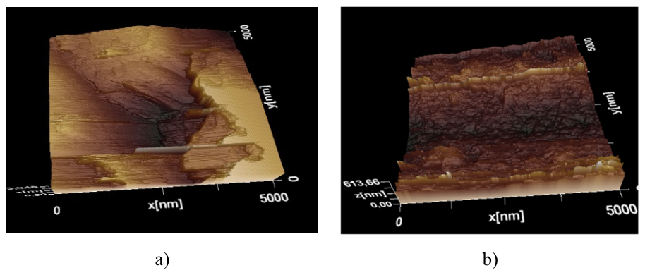
Figure 3.
The structure of the coal surface after electro-impulse treatment: a) - top view, b)- 3D image (a magnification of 10 nm).
Figure 3.
The structure of the coal surface after electro-impulse treatment: a) - top view, b)- 3D image (a magnification of 10 nm).
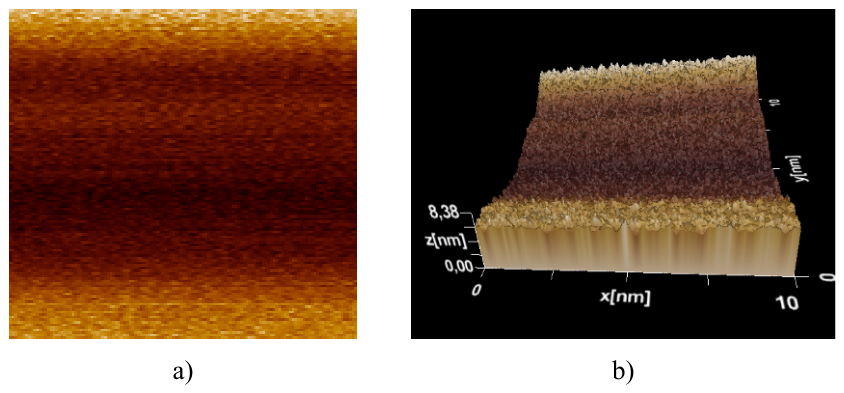
Figure 4.
Nozzle profile using the Vitoshinsky formula [18].
Figure 4.
Nozzle profile using the Vitoshinsky formula [18].
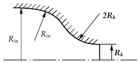
Figure 5.
Nozzle with tangential swirl for atomizing coal-water fuel: (a) general view; b) internal part with tangential swirl.
Figure 5.
Nozzle with tangential swirl for atomizing coal-water fuel: (a) general view; b) internal part with tangential swirl.
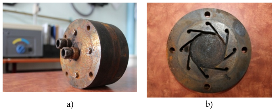
Figure 6.
Temperature field image in a nozzle cross-section.
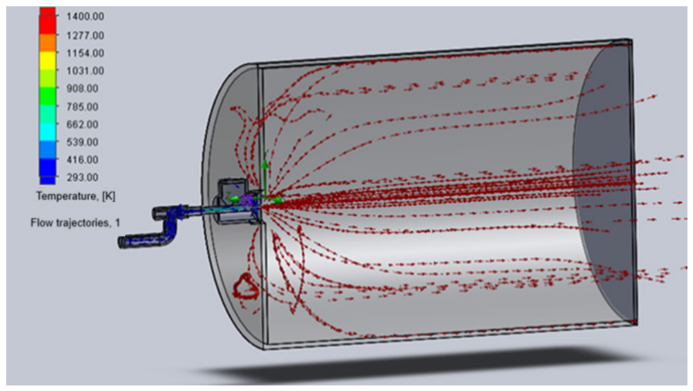
Figure 7.
Schemе of a combustion installation for liquid CWF, injected through a radially rotating nozzle: 1 – compressor; 2 – high-pressure fuel storage tank; 3 – high-pressure fuel tank; 4 – nozzle; 5 – burner; 6 – combustion chamber; 7 – fan; 8 – pre-burner.
Figure 7.
Schemе of a combustion installation for liquid CWF, injected through a radially rotating nozzle: 1 – compressor; 2 – high-pressure fuel storage tank; 3 – high-pressure fuel tank; 4 – nozzle; 5 – burner; 6 – combustion chamber; 7 – fan; 8 – pre-burner.
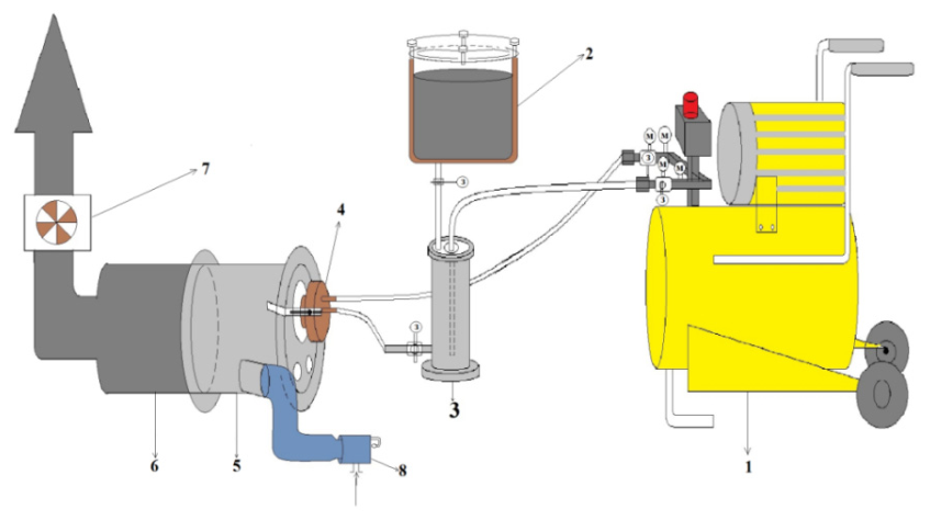
Figure 8.
External view of the coal-water combustion plant.
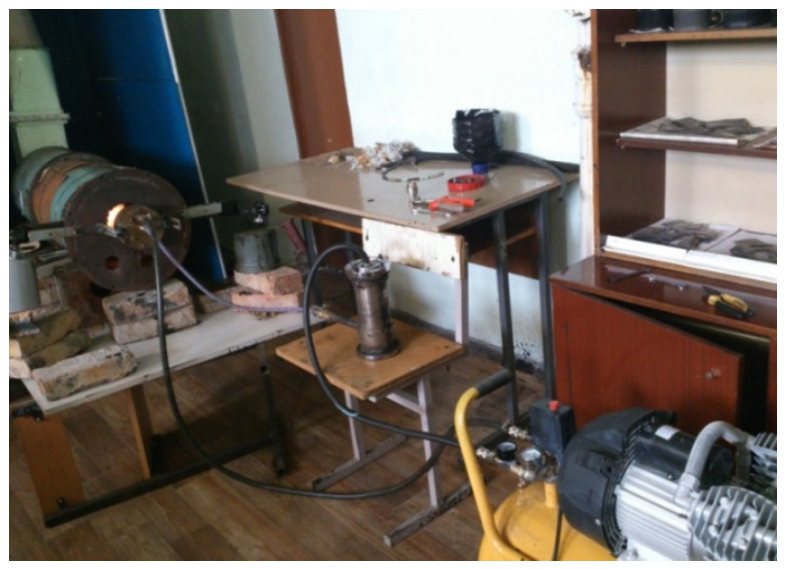
Figure 9.
Biogas plant with a heating system using coal-water fuel combustion. 1 - bioreactor, 2 - biomass loading, 3 - cleaning pipe, 4 - drain pipe, 5 - biomass heating device, 6 - pressure gauge, 7 - temperature sensor, 8 - gas outlet, 9 - sample collection, 10 - bubbling system, 11 - boiler, 12 - consumers, 13, 14 - coal-water fuel preparation and combustion device.
Figure 9.
Biogas plant with a heating system using coal-water fuel combustion. 1 - bioreactor, 2 - biomass loading, 3 - cleaning pipe, 4 - drain pipe, 5 - biomass heating device, 6 - pressure gauge, 7 - temperature sensor, 8 - gas outlet, 9 - sample collection, 10 - bubbling system, 11 - boiler, 12 - consumers, 13, 14 - coal-water fuel preparation and combustion device.
Disclaimer/Publisher’s Note: The statements, opinions and data contained in all publications are solely those of the individual author(s) and contributor(s) and not of MDPI and/or the editor(s). MDPI and/or the editor(s) disclaim responsibility for any injury to people or property resulting from any ideas, methods, instructions or products referred to in the content. |
© 2026 by the authors. Licensee MDPI, Basel, Switzerland. This article is an open access article distributed under the terms and conditions of the Creative Commons Attribution (CC BY) license (http://creativecommons.org/licenses/by/4.0/).
Copyright: This open access article is published under a Creative Commons CC BY 4.0 license, which permit the free download, distribution, and reuse, provided that the author and preprint are cited in any reuse.