

Submitted:
07 May 2026
Posted:
12 May 2026
You are already at the latest version
Abstract
Both Noise Radar (NR) and Quantum Radar (QR), with alleged common features, aim to use the randomness of the transmitted signal to enhance radar covertness and to reduce mutual interference. While NR has been prototypically developed and successfully tested in many environments by different organizations, research and development investments on QR did not bring to practically operating prototypes. Starting from the well-known fact that radar detection depends on the energy transmitted on the target, the detailed evaluations in this work show that the detection performance of all the QR types proposed in the literature are well below the ones of a much simpler and cheaper equivalent “classical” radar set, for example of the NR type. Moreover, the absence of a “Quantum radar cross section” different from the well-known radar cross section is explained. From these facts it results that, in spite of alleged advantages in some literature, Quantum Radar proposals cannot lead to useful results, including, of course, the detection of stealth targets.
Keywords:
quantum radar
; quantum illumination
; noise radar
; radar range
; quantum two-mode squeezing radar
1. Aim of This Paper
This paper is aimed to help the radar community to better understand the intrinsical limitations of the proposed Quantum Radar (QR) technologies and demonstrators. The question is answered whether a fielded and operating QR system might really outperform an “equivalent” classical radar, where the term “classical” is opposed to “quantum” and includes the particular architecture known as Noise Radar (NR). Moreover, it is investigated whether (or not) a QR could reasonably detect an air or a marine target outside a laboratory, i.e. at least at hectometer or kilometer ranges, with performance similar to the one of a cheap (order of thousand €) and simple marine radar [1]. In such a frame, detection and ranging capabilities for the QR are critically discussed and compared with Noise Radar ones. The results have been anticipated by the same Authors in the ArXiv file 2403.00047v1 and in Techrxiv file 177032898.88332542/v1.
2. Analysis of the Literature
In the last two decades many theoretical and experimental research activities have been aimed to apply quantum technologies in the fields of cryptography, computing, communications and sensing. In this context, sometimes it was claimed that a Quantum Radar (QR) has the potential to outperform classical radar permitting, in some cases, the detection of stealth targets [2,3,4,5,6].
The early QR literature is oriented to quantum physics with a very few contributions considering system architecture and operational aspects. Despite the radar context, some laboratory set-ups refer to optical wavelengths (i.e. Lidar, not Radar) and most tests are indoor, not outdoor. For example, the “quantum radar demonstrator” of Figure 3 of [7] has the transmitter connected to a horn antenna facing another (receiving) horn antenna at a distance of less than one meter (both horns being fixed with adhesive tape on a desk) i.e. the radar target is simply absent. The experiment in [7] is carried out with a transmit-receive propagation attenuation close to the unity while, in real radar operation (e.g. for aircraft tracking applications), the two-way attenuation at X band is of the typical order of (for instance ten watts transmitted signal generates echoes of order of picowatt or less at normal kilometric target distances). Conversely, in the aforementioned literature one founds a much lower attenuation: see for instance [8] where the results shown in Figure 2 and Figure 3, according to their captions, are obtained with a round-trip transmissivity of mere two orders of magnitude, i.e. . This attenuation, present in most QR paper written by the physics community, corresponds to a radar Range of the order of one metre (in the X-band, using horn antennas and for a target of radar cross section).
The literature on Quantum Radar includes both physics (often, under the name “Quantum Illumination” [9,10]) and engineering topics. Focusing on the latter, the well-known IEEEXplore repository (https://ieeexplore.ieee.org/Xplore/guesthome.jsp) collects most of the papers; a search in the time span 2012-2025 was carried on by the presence of the words “Quantum” followed by “Radar” in the title, followed by a manual check to avoid the inclusion of papers not really related to the QR, [11]. The years 2020 and 2021 showed the maximum interest concerning QR; this interest decreases in 2022 – 2025.
More recently, in Scopus (one of the largest multidisciplinary bibliographic and citation databases of scientific literature, https://www.scopus.com/pages/home#basic), we implemented a search related to the time span 2009 – 2025, using the following criteria: “Quantum radar” in the title with “Quantum Entanglement” or “Quantum Radar” in the keywords. The results are shown in Figure 1 and agree with those of [11].
The publications are 108, i.e. 69 conference papers (63.9%), 36 articles (33.3%) and 3 reviews (2.8%). In 2025, there are still 6 “endurance publications”; the analysis of their content shows us how slowly the “bubble” is deflating [11].
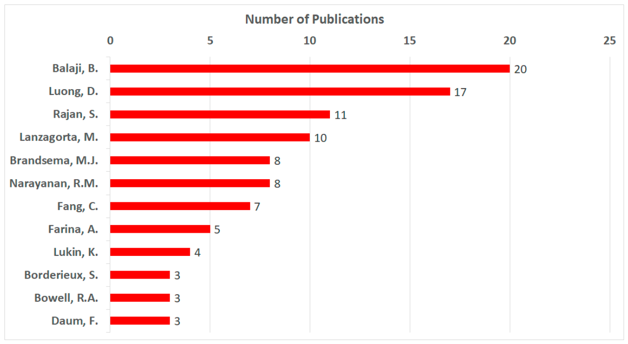
Considering the same database of Figure 1, in Figure 2 the number of articles by Authors with at least three publications are shown. The first three authors (Balaji, Luong and Rajan) work in Canada, where an intense research activity was developed between 2020 and 2023.
Figure 2.
Articles on Quantum Radar by Authors as referenced in Scopus from 2009 to 2025.
3. Classical Radar, Noise Radar and Quantum Radar
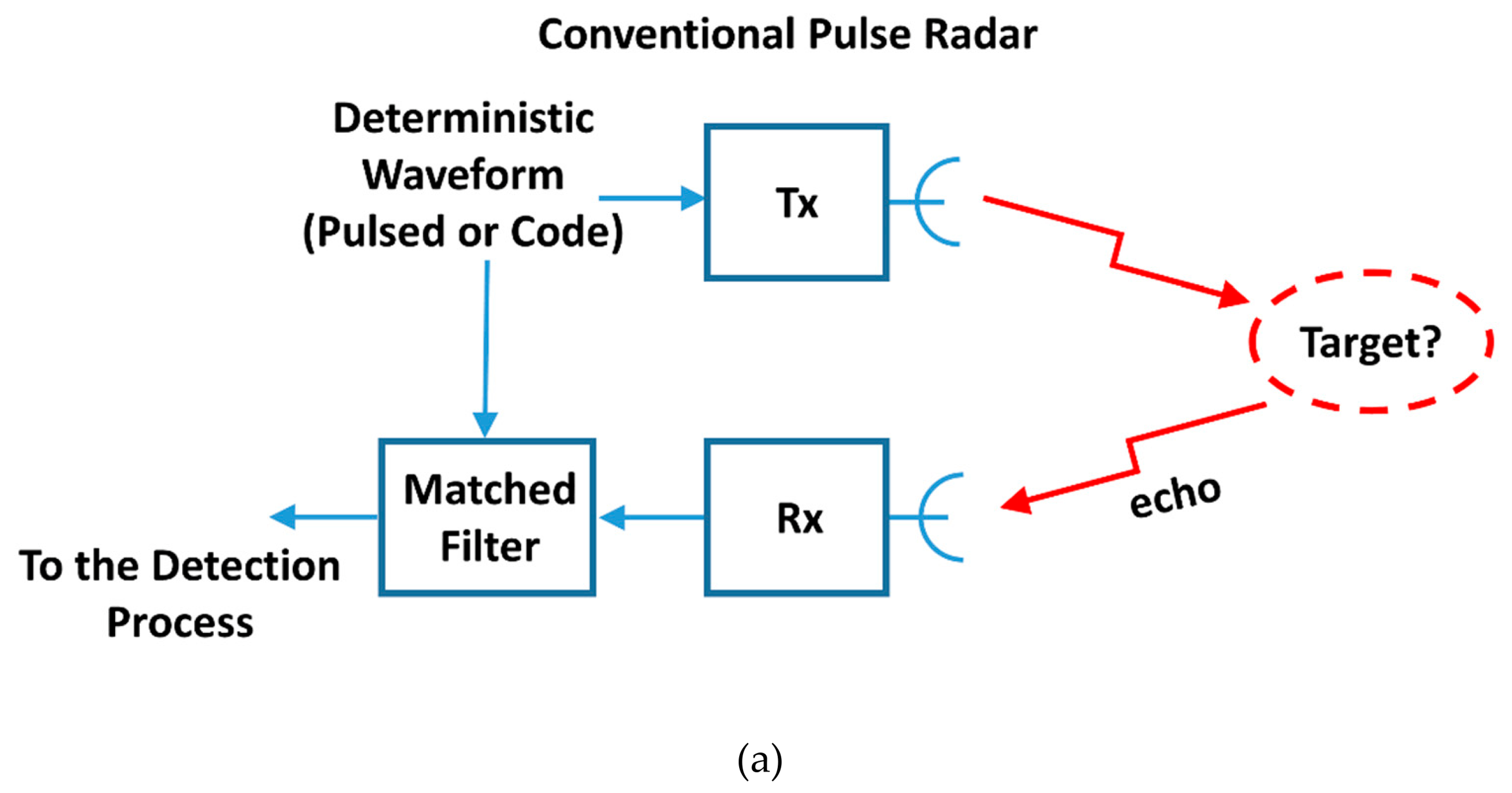
A classical radar’s (CR) operation is shown in Figure 3a: the received signal is correlated with a template of the transmitted one (matched filtering). Most classical radar waveforms have a constant amplitude (i.e. are phase-coded or simply not coded at all) in order to exploit at best the power amplifier, granting a Peak-to-Average Power Ratio (, [12,13,14]) equal to the unit in order to maximize, within the bound of the maximum transmittable power, the received energy in the dwell time.
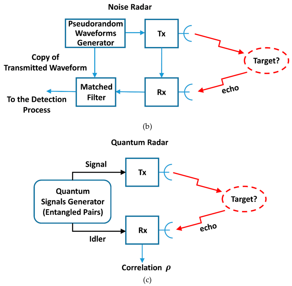
The architecture of certain proposed types of quantum radar [15,16] make them allegedly similar to a Noise Radar (NR), Figure 3b. Tailoring of the waveform lowers the range sidelobes at the output of the compression filters ensuring a close to the unit as shown in [17]. On the other side, the received signal of a QR is correlated with the idler signal entangled with the transmitted one (Figure 3c), which is a realization of the random process of generation of microwaves photons [9]. Comparing NR with QR, it is clear that the NR approach shows the advantage in “tailoring” the transmitted waveforms [17,18,19,20].
Figure 3.
Block diagram comparison of (a) conventional radar (CR), (b) noise radar (NR), and (c) quantum radar (QR).
Figure 3.
Block diagram comparison of (a) conventional radar (CR), (b) noise radar (NR), and (c) quantum radar (QR).
4. Noise Radar: An Overview
4.1. Waveform Generation in Noise Radar
The history of Noise Radar (NR) is quite old: it was introduced in 1959 [19] by Horton for a high-resolution distance measurement system. The generation of noise radar signals, now based on digital techniques, was first implemented using generation of “chaotic” signals from an analogue source. The preferred solution in modern NR is based on pseudo-random number (PRN) generators [17,18,19,20,21], as shown in the high-level block diagrams of Figure 4 and Figure 5. The randomness of the transmitted waveform, with its (typically it is equal to 10 – 12), may significantly reduce its energy, [12] by as much as 12 dB. Moreover, pulse compression poses the problem of Range-sidelobes at the output of the coherent integration.
Both problems may be faced by a suited “tailoring” of these signals, [17], allowing a suited to the power budget, e.g. as low as (corresponding to a loss) and a Peak Sidelobe Level () as low as (typically) below the main lobe.
4.2. Radar Range
For continuous-emission NR the maximum range can be evaluated as [21]:
with the usual meaning of symbols: transmitted power, antenna gain in Tx e Rx, wavelength, losses, RCS, minimum SNR (depending on the target model), Boltzman constant, system temperature and bandwidth, where is the coherent integration gain, equal to the product , with being the coherent integration time (generally denoted in QR), equal to (or less than) the dwell time.
5. Quantum Radar
5.1. Overview of QR Operation
Two main classes of quantum radars (neglecting the outdated interferometric quantum radar referenced in [22]) have been proposed in the literature: quantum illumination (QI) radar [9,10], and quantum two-mode squeezing (QTMS) radar [7].
The concept and the protocol of “quantum illumination” were introduced in 2008 [9,10] and is based on a generation of pairs of entangled photons, the idler and the signal photon. The signal photon is sent to region where a target could be present, while the idler is stored. If the target is present, the signal photon may be received by the radar after the transmission delay, otherwise the radar only receives noise photons. Each received photon is compared with the idler.
Of course, in addition to the basic detection function, a radar set is (at least) requested to measure the distance of the targets, i.e. the ranging, which is not trivial using the quantum illumination protocol, as quoted in [23]:“… hinging on a joint-measurement between a returning signal and its retained idler, an unknown return time makes a Quantum Illumination-based protocol difficult to realise”.
Aimed to solve this problem, the QTMS protocol, which operates in a way closer to that of a conventional (or noise) radar, has been implemented as a laboratory demonstrator (but with no target), [7,15,16].
It circumvents the ranging problem as follows. In the QTMS radar, the reference-entangled beam is immediately measured using heterodyne (in-phase) and (quadrature) detection and retained within the system, while the received signal is measured at its arrival. Hence, the correlation of reference and the received signals is computed.
According to the theory, the QI protocol should yield better results, but implementing a quantum memory storing the reference signal until the arrival of the corresponding echo signal is really difficult, especially at radar (microwave) frequencies.
Hence, the QTMS radar is mainly considered here. It requires maximally entangled pairs of photon modes; therefore, the process of spontaneous parametric down-conversion is the most generally used, generating a Gaussian two-mode squeezed-vacuum state at microwave frequencies.
Despite the loss of the entanglement due to the interaction with the environment, QTMS radar is aimed to exploit the correlation caused by the entanglement to detect the signal photons in noise when the correlation is computed many times. The number of pairs (or “of modes”) , is referred to as the time-bandwidth product: , where is the duration of the emitted signal (less than, or equal to, the time-on-target) and is the operating bandwidth. In each mode, an average number of photons is transmitted; for , due to the decoherence, the classical physics applies. Hence, a quantum advantage is fully attained when . In practice, when or the quantum effects become negligible, and the classical radar operation applies.
Among the (not numerous) evaluations, in 2020 Barzanjeh et. al. [24] carried out an experimental verification of Quantum Illumination in X band, with generation and amplification of entangled microwave photons (frequencies: and ) in cryogenic conditions (at ) and with a target at room temperature and at a fixed distance of one metre. The experiments showed advantage over the optimal classical illumination at , the difference with respect to the theoretical being explained by the limitations due to the experimental set up.
5.2. Structure, Cost and Capabilities of QR
The basic “Quantum” part of a QR set is the generator of microwave-entangled photons. In [25] one finds (at Section I) ,the description of the operation of a Josephson Parametric Amplifier (a microwave resonant cavity terminated by a Superconducting Quantum Interference Device, or SQUID) operating very close to the absolute zero temperature (i.e. at a few milli-Kelvins) within a bulking dilution refrigerator with the size of a large car and including the He-3 and He-4 large Dewar’s, and with a power consumption as large as . Its high cost (order of € according to [26]) causes the radar cost of the QR set (Figure 1 of [26]) to be five orders of magnitudes greater than the equivalent conventional radar.
In front of the significant SWaP (Size, Weight and Power) implicit in the QR technology, one may ask what radar performance enhancement arises from the Quantum approach.
In the literature there are many theoretical evaluations, indicating an alleged gain (depending on the quantum protocol, on the average number of transmitted signal photons and of noise (background) photons ) of or or (the highest figure is the one generally cited but never achieved, being theoretically attainable with a quantum computer in the receiving part).
An overview of the attained Quantum Advantage is found in [27] with a synthesis of experiments. These evaluations show that the “long-distance detection” of QR in the title of [6] will never apply to real world situations, in spite of any known or anticipated technological improvement.
Of course, negative results apply to the alleged detection of stealth targets, see [3,5]. In the Abstract of [5] we read: “… making our MQI (Microwave Quantum Illumination) system a promising candidate for the detection of stealth objects”.
In reality, stealth targets call for a high-power illumination which is contrasting with the QR nature; note that the radar cross section (RCS) of a target (either stealthy or not) does not change when QR is used. This is shown in [28,29]: the path of each photon to the target is not well defined because of the position uncertainty, and this causes a quantum interference which exactly replicates, in the far-field limit where the radar cross section is defined, the classical scattering behaviour of electromagnetic waves. A simpler reasoning tells us that the radar cross section of an object is the same irrespectively of the type of radar, either conventional (i.e., classical) or of the quantum type. In fact, the target “cannot know” whether a photon impinging on it has an idler stored somewhere, or not, the backscatter being the same in both cases. Of course, in principle, it is always possible to compute the RCS “photon by photon” by the quantum mechanics methods in place of the Maxwell’s equations, deriving the classical electric field scattering integral using a purely quantum construction. Unfortunately, in spite of the very clear paper [29], some authors continue to neglect or ignore it, and to write about a non-existent quantum RCS [46,47,48].
5.3. The Background Noise Power in QR
From the Bose-Einstein statistics (as applicable in the cases of zero chemical potential), the average number of photons per mode (where the subscript stands for background) versus the frequency at a system temperature (in Kelvins) is:
with the Boltzmann’s constant and the Planck’s constant. At microwave frequencies (X band) and at room temperature where , Eq. (2) becomes: and the background noise power inside the bandwidth equals the classical relationship:
Figure 6 shows Eq. (2) with from to . The QR system has the optimum quantum advantage for an average photon number , and loses the advantage nearly completely for a number of photons greater than about four or five: the blue area () is the optimal one for quantum operation.
The green subset of the blue area represents the average background photons at microwave () frequency with a temperature below . The upper pink area refers to a CR and represents the numerous background photons from a favourable case of to a more frequent radar situation of (a worst case of is also shown).
5.4. Power Considerations for the Range of Quantum Radar
Determining the maximum operational Range of a radar set seems an easy task by a computation of the Radar Equation, Eq. (1), standardized by the classical report (and the ensuing book) on Pulse Radar Range by L. V. Blake, [30]. However, the matter is more difficult when considering the many factors affecting the computation (target fluctuations, equipment losses, multipath, internal and external disturbances and more), so much that the real operational radar Range sometimes may be as short as half of the computed Range as mentioned by M.I. Skolnik, [31].
The literature on the Range performance of a QR simplifies the disturbance, i.e. the “background noise” due to photons. In reality, the radar disturbance includes unwanted echoes, propagation effects, antenna noise, radiofrequency connections and the active reception stages, [30,31,32].
In [33] the system noise temperature is considered in the range . The lower value is quite optimistic: of a radar set is typically close to, or above, , due to the sum of contributions by the antenna (), by the radiofrequency () connections of the antenna with the receiver (including the duplexer and the rotary joint - if any) and, finally, by the receiver itself.
The power budget of QR Range is related to three facts:
- a)
- The energy in a single photon at microwave or millimetre-wave frequencies is extremely small when compared to the one of a Conventional Radar (CR) pulse: therefore, being the number of modes defined by operational constraints, one could try to increase the average number of signal photons per mode , but this brings back to the classical operation. With a few photons per mode, say , optimal for the quantum-advantage, the transmitted energy per microwave radar pulse (i.e. per mode) is to orders of magnitude below the one required for detection. Moreover, the amplification of the radar signal would nullify the quantum advantage, [27].
- b)
- Theoretically, a Quantum Illumination (QI) system shall provide a theoretical factor-of-four () improvement in the error-probability exponent over its classical counterpart of the same transmitted energy [34]. The practical QR implementations limit this advantage to lower figures, order of to only, [27,35].
- c)
- The increase of the number of modes for the (necessarily limited) available signal bandwidth would generate an increase of the dwell time . Values of above some threshold (order of a few milliseconds to hundreds of milliseconds depending upon the type and dynamics of target) would make the system prone to the effects of target scintillation and of Doppler frequency, destroying the correlation with the stored replica, and nullifying the advantage.
Summing up, we quote from the Introduction of [35]: “Our main conclusion is that, while realizable experimentally, useful application of microwave quantum radar protocols to any conventional setting is unrealistic because of fundamental restrictions on power levels”.
The use of QR has been recently proposed for biomedical sensing [25], a very short range (order of meters) case.
Radars were introduced for healthcare applications of detecting human vital signs in 1975, with heart rate measured at distances of the order of using sub-micro-watt power levels, [36].
Non-invasive microwave techniques for remote sensing of respiratory and circulatory activity have been developed at continuous-wave frequencies between and with average power densities from to per square cm, i.e. much lower than the ones due to the cellular phones. Some systems measure pressure pulse, heart rate, and respiration rate.
Finally, the use of electromagnetic spectrum is regulated by the ITU (an ONU agency), and the radar bandwidth allocation generally does not exceed of the central frequency of each sub-band. Hence, the radar transmission in an ultra-wide band is limited to indoor, very short-Range operation [37]. Summing up, the QR is not an option in biomedical and healthcare applications, because: (i) the SWaP limitations are important (see Section 5.2); (ii) the short distances imply a very low transmitted microwave power, for which a “quantum advantage” is not relevant.
5.5. Exemplary Range Computations for Quantum Radar
Some computations for a representative QR are shown in the following to sustain the previous discussion. The related main parameters are:
- ○
- f0: operating (central) frequency.
- ○
- : wavelength.
- ○
- B: operation bandwidth, i.e. radar frequencies from to
- ○
- T: signal duration (less or equal to the dwell-time).
- ○
- M = B · T: number of modes.
- ○
- σ: radar cross section of the target.
- ○
- G: antenna gain (the same for Tx and Rx antenna).
- ○
- TS: system noise temperature.
- ○
- SNR: signal-to-noise ratio.
- ○
- aR: free-space attenuation of the radar equation at distance R (the same in both ways).
- ○
- A non-fluctuating target is assumed.
First, the free-space two-way attenuation is:
Hence, the received power from a target at a distance is:
where is the average number of photons per mode (Poisson statistics) and is the quantum advantage. Hence, the signal-to-noise ratio is:
where is the integration time.
Hence, to achieve a positive (in ) at Range , the Quantum Radar shall operate with a time duration:
At the widely used X band ( order of ) e.g. at frequency ( ), assuming a bandwidth (that is about of the central frequency ) and, for the sake of simplicity, , , at with an antenna gain (the same in transmission and in reception) of () and with , it results: (which is about ) and . Hence, Eq. (7) gives: (order of days!) which appears absurd. For and , it results and respectively.
In the ideal case of target, at , the signal-to-noise-ratio is times greater than at and an operation with same should permit to be at the order of magnitude of ten milliseconds.
5.6. Quantum Two-Mode Squeezing Radar and Noise Radar
In some papers [35,38,39] quantum radar is proposed because of its low probability of intercept (LPI) features due to the intrinsic randomness of its emission. Similar characteristics belong to noise radar. Hence, it is interesting to compare the performance of NR and QR in equivalent system configurations [40].
From Eq. (4) and Eq. (6) the maximum range for a QR can be evaluated as:
where is the quantum advantage and the total loss.
A simple comparison figure is the ratio of maximum ranges: .
The maximum range for continuous-emission noise radar is evaluated by Eq. (1), while for quantum radar, is computed by Eq. (8). In situation of equal losses, we have:
Assuming, as a reasonable approximation, and taking into account that the antenna and the receiving parts operate close to room temperature, i.e., and , Eq. (9) becomes:
where ) is the energy coherently transmitted on the target, is the number of modes, and is the number of photons transmitted by the NR: .
For , , it results that .
To obtain , one has to set , i.e., an unthinkable bandwidth, .
A similar evaluation is presented in [41], where, however, cooling of both Conventional Radar (CR) and QR sets at is considered, and the ratio between “Equation (14)” and “Equation (12)” of [41] leads to a ratio equal to: (note that in [41], the number of modes is in place of ), which is rather in agreement with the ratio of red and blue curves of its “Figure 3” (referring to the X-band and to , which for the bandwidth corresponds to an unrealistic illumination time of a mere ) but not with the evaluations shown in this chapter. Likely, there are errors in the computations (called “simulations”) of [41], and probably the integration gain was not considered.
However, it is necessary to mention the ensuing paper [42] of the same authors, where the processing gain of CR was considered, and it was confirmed that the conditions , and maximize the advantage of quantum illumination but, unavoidably, lead to very short radar ranges. The conclusions of [42] include: “... although QI shows its advantages, this advantage is limited to the case of very weak transmitted signal power, so it may be a challenge for applying QI to radar remote detection”.
From Eq. (10), one can easily compute the frequency that makes the maximum range of the QR equal to the NR, i.e. . Posing , with (fractional bandwidth), it results that:
Figure 7 shows Eq. (11), confirming that quantum sensing tends to become useful (i.e., with the same maximum range of a NR) at very high frequencies, well above microwave, and at very low power levels.
(and corresponding wavelength), making , Eq. (11). with .
For an analysis of QR operation above millimetre-wave frequencies, the interested reader may see [33]. The pertaining computation of the QR range is at and at , with atmospheric attenuation not taken into account (unlike in [43]).
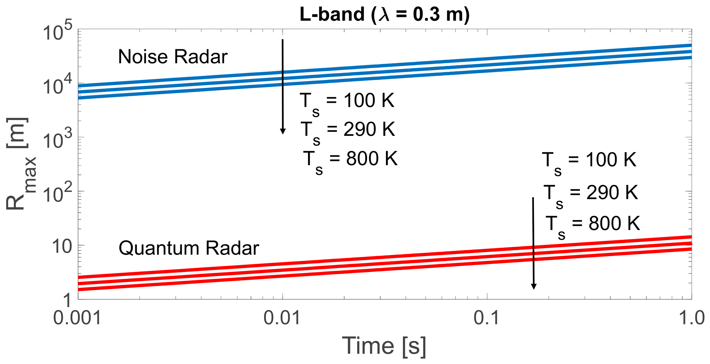
Figure 8 shows a comparison between the maximum ranges of QR and NR at similar operating conditions. For the quantum radar, the maximum range, Eq. (8), is in the order of meters, while a noise radar improves the range (Eq. (1)) to the order of tens of kilometres (the system temperature is set to the realistic values of and , and to the “bad” value of ). The same analysis in L-band gives the result shown in Figure 9, where we notice that no differences appear for the QR w.r.t Figure 8.
In fact, with the central frequency of the QR increasing, the increase of the photon’s energy compensates for the increase of the receiver noise (a receiving bandwidth equal to 10% of the central frequency and a constant antenna gain of 30 dB are assumed throughout this paper).
. The Noise Radar transmitted power is 100 mW (for 10 µW the lines are shifted below by a decade),. No atmospheric attenuation, no clutter, no radiofrequency interference.
5.7. Specific Noise Radar’s Advantage over Quantum Radar
The above discussion about NR and QR has to be complemented by a few considerations. First, differently from Classical Radar and NR, QR signals cannot be “tailored” and are inherently random, thus causing relatively large sidelobes after pulse compression.
Second, important for the radar Range point of view, QR signals have a poor , whose estimated value depend on the chosen amplitude saturation point. The related loss, around ten or eleven decibels [17], is much larger than all the values of “quantum advantage” presented in the literature, and cancels any quantum advantage in any comparison of the QR with the NR, and of course with any classical radar using “phase only” (constant amplitude) signal coding.
6. Conclusions
In addition to the afore-mentioned Range problems of QR, one should consider the Range measurement in Quantum Radar, whose proposed solutions – out of the scope of this paper – add complexity to a yet – complicated equipment.
Most papers on QR describe the detection problem as the decision of the hypothesis: (a) a target is present at distance R, (b) no target at distance R, with the pertaining “error probability”, while the correct radar detection strategy is based on the Neyman-Pearson approach.
Other relevant considerations such as technical feasibility, operational problems (and, last but not least, cost) are found in [26,27]. Regarding the cost, QRs require costly cryogenic generators (in the range) using Helium-4 and in some cases the hardly available Helium-3.
A synthesis on the operational problems of QR and its readiness is presented in [44] with numerous References.
The above considerations indicate that the laws of physics do not allow a Quantum Radar, irrespective of the used protocol, to perform better than a Conventional Radar.
Summing up:
- With a constraint on the transmitting power, a limited quantum advantage is alleged in some literature. The experimented value of this advantage is of the order of 1 dB.
- The random nature of the transmitted signal does not permit any “tailoring”, resulting to a Peak-to-Average-Power-Ratio (PAPR) related loss much greater than the above advantage.
- If a low-powered signal of a quantum noise radar is amplified, then a classical noise radar results, which outperforms the quantum radar.
- If enough noise is added at the idler level, such as when it is amplified or measured heterodyne, then all the quantum advantage is lost.
Conclusions similar to the ones of this paper are finally appearing in widely-distributed journals such as Science [45] from which we report the following: “Even if experimenters can overcome the technical hurdles, quantum radar would still suffer from a fatal weakness, researchers say. The entangled pulses of microwaves provide an advantage only when the broadcast pulses are extremely faint. The extra quantum correlations fade from prominence if pulses contain significantly more than one photon—which is overwhelmingly the case in real radar. ‘If you crank up the power, you won’t see any difference between the quantum and the classical,’ Barzanjeh says. And cranking up the power is a much easier way to improve the sensitivity”.
Again in [45] it is noticed that it is difficult to establish a useful and practical microwave application of quantum sensing even with the full advantage by an entangled source when a simpler classical system will perform better with a higher power output and a cheaper and simpler setup. Furthermore, the alleged military advantage of a quantum radar due to its covertness, i.e. the LPI features, is practically immaterial due to its extremely short operating range.
Despite the above considerations, the QR is present in the 2025 literature (see for instance [46,47,48]) and the alleged “anti-stealth” feature of a QR is still found in the recent literature [47,48] and on the Internet.
Pertaining considerations and “lessons learned” are discussed in [11].
Author Contributions
Conceptualization, G.G.; methodology, G.G. and G.P.; investigation, G.G., G.P. and F.D.; writing—original draft preparation, G.P.; writing—review and editing, G.P.
Funding
No special funding was applied to this work
Data Availability Statement
More data may be delivered by the corresponding Author under reasonable requests. Some Supplementary Information is found online at https://uniradarlab.com/supplementary-information/.
Acknowledgments
The Authors wish to thank CNIT- National Inter-University Consortium for Telecommunications - for supporting the payment of the APC.
Conflicts of Interest
The Authors declare the absence of conflicts of interest
References
- Galati G., Pavan G. Radar environment characterization by signal processing techniques. In Proc. of IEEE International Symposium on Signal Processing and Information Technology (ISSPIT), Bilbao, Spain, 18 - 20 December 2017, pp. 024-029. [CrossRef]
- Hill G. Quantum Radar Is Stealth Radar: Examining the Potential Impact on the Defence Team. Service Paper JCSP 48. https://www.cfc.forces.gc.ca/259/290/24/192/Hill.pdf.
- Vella H. Quantum radars: Expose stealth planes. Engineering & Technology, 2019, Vol. 14, n. 4, pp. 42-45. [CrossRef]
- Yung M. H., Meng F., et al. One-shot detection limits of quantum illumination with discrete signal.npj Quantum Information, 2020, 75. [CrossRef]
- Livreri P., Enrico E., Fasolo L., et al. Microwave Quantum Radar using a Josephson Traveling Wave Parametric Amplifier. Proc. of IEEE Radar Conf. New York City, USA, 21-25 March 2022, pp. 1-5, 2022. [CrossRef]
- Livreri P., Enrico E., Vitali D., Farina A. Microwave Quantum Radar using a Josephson Traveling Wave Parametric Amplifier and a Phase-Conjugate Receiver for a long-distance detection. In Proceedings of IEEE Radar Conference, San Antonio, TX, USA, 01-05 May 2023. [CrossRef]
- Luong D., Chang C. W. Vadiraj A. M., et al. Receiver operating characteristics for a prototype quantum two-mode squeezing radar. IEEE Transaction on Aerospace and Electronic Systems, 2020, Vol. 56, No. 3. [CrossRef]
- Amat I. C., et al. Advantages and Limitations of Quantum Radar. In Proc. of 17th European Conference on Antennas and Propagation (EuCAP), Florence, Italy, 26-31 March 2023. [CrossRef]
- Lloyd S. Enhanced sensitivity of photodetection via quantum illumination. Science 2008, 321, 1463-1465. [CrossRef]
- Tan S.H., Erkmen B.I., Giovannetti V., Guha S., Lloyd S., Maccone L., Pirandola S., Shapiro J.H. Quantum illumination with Gaussian states. Phys. Rev. Lett. 2008, 101, 253601.
- Galati G., Pavan G., Daum F. (2026) From the Rise and Fall of Quantum Radar to Proposed Improvements of Research Assessment, Technium Social Sciences Journal. Constanta, Romania, 80(1), pp. 347–371. [CrossRef]
- Savci K., Galati G., Pavan G. Low-PAPR waveforms with shaped spectrum for enhanced low probability of intercept noise radars. MDPI Remote Sensing, 2021, 13(12), 2372. [CrossRef]
- Huang Y., Hu S., Ma S., et al. Designing Low-PAPR Waveform for OFDM-Based RadCom Systems. IEEE Transactions on Wireless Communications, 2022, Vol. 21, no. 9, pp. 6979-6993. [CrossRef]
- Varshney P., Babu P., Stoica P. Low-PAPR OFDM Waveform Design for Radar and Communication Systems. IEEE Transactions on Radar Systems, 2023, Vol. 1, pp. 69-74, 2023. [CrossRef]
- Luong D., Balaji B., Rajan S. Quantum Radar: Challenges and Outlook: An Overview of the State of the Art. IEEE Microwave Magazine, 2023, Vol. 24, no. 9, pp. 61-67. [CrossRef]
- Luong D., Rajan S., Balaji B. Entanglement-Based Quantum Radar: From Myth to Reality. IEEE Aerospace and Electronic Systems Magazine, 2020, Vol. 35, no. 4, pp. 22-35. [CrossRef]
- Galati G., Pavan G., Wasserzier C. Signal design and processing for noise radar. EURASIP Journal on Advances in Signal Processing, Article number: 52 (2022). [CrossRef]
- Kulpa K. Signal Processing in Noise Waveform Radar, Artech, 2013. ISBN: 9781608076611.
- De Palo F., Galati G., Pavan G. Wasserzier, C.; Savci, K. Introduction to Noise Radar and Its Waveforms. MDPI Sensors. [CrossRef]
- Galati G., Pavan G., Wasserzier, C. Interception of Continuous-Emission Noise Radars Transmitting Different Waveform Configurations. In Proceedings of 23rd IRS, Gdansk, Poland, 12-14 Sept. 2022, pp. 153-158. [CrossRef]
- Galati, G., Pavan G. Measuring the Anti-Intercept features of Noise Radar waveforms: the way ahead. In Proceedings of IEEE 9th International Workshop on Metrology for AeroSpace, Pisa, Italy, 27-29 June 2022, pp. 174-178. [CrossRef]
- Lanzagorta M. Quantum Radar, Springer Nature Switzerland, ISBN 978-3-031-01387-4.
- Karsa A., Pirandola S. Energetic Considerations in Quantum Target Ranging, Quantum Physics, arXiv: online: . [CrossRef]
- Barzanjeh S., Pirandola S., et al. Microwave Quantum Illumination using a digital receiver, Science Advance, 8 May 2020, Vol 6, Issue 19. [CrossRef]
- Luong D., Balaji B., Rajan S. Biomedical Sensing Using Quantum Radars Based on Josephson Parametric Amplifiers. In Proc. of International Applied Computational Electromagnetics Society Symposium, Hamilton, Canada, 01-05 August 2021, pp. 1-4. https://ieeexplore.ieee.org/document/9528545.
- Daum F. A system engineering perspective on quantum radar. In Proceedings of IEEE International Radar Conference, Washington, DC, USA, 8-30 April 2020, pp. 958-963. [CrossRef]
- Sorelli G., Treps N., Grosshans F., Boustet F. Detecting a Target with Quantum Entanglement, IEEE AES System Magazine, 2022, Vol. 37 n. 5, pp.68- 90. [CrossRef]
- Brandsema M., Narayanan, R. M., Lanzagorta, M. Theoretical and computational analysis of the quantum radar cross section for simple geometric targets. In Quantum Information Science; Springer: Berlin Heidelberg, Germany, 2017.
- Brandsema M., Lanzagorta M., Narayanan R. M. Quantum Electromagnetic Scattering and the Sidelobe Advantage. In proceedings of IEEE International Radar Conference, Washington, DC, USA, 28-30 April 2020, pp. 755-760. [CrossRef]
- Blake L. V. A Guide to Basic Pulse-Radar Maximum-Range Calculation - Part 1 - Equations, Definitions, and Aids to Calculation”, NRL Report 6930 (Second Edition of NRL Report 5868), December 23, 1969.
- Skolnik M. I. Introduction to Radar Systems, Mc Graw Hill, Third Edition. ISBN 0-07-044533-8.
- Doerry A. Noise and Noise Figure for radar receivers. SANDIA Report Number: SAND2016-9649 647834, October 2016 https://www.osti.gov/servlets/purl/1562649.
- Wei R., Jun Li, Weihao Wang, Zhou Ye, Chunlei Zhao Qinghua Guo Evaluating the detection range of microwave quantum illumination radar. IET Radar Sonar and Navigation, 2023. [CrossRef]
- Luong D., Balaji B. Quantum two-mode squeezing radar and noise radar: covariance matrices for signal processing. IET Radar Sonar Navigation, 2020, Vol. 14 Issue 1, pp. 97-104. [CrossRef]
- Jonsson R., Ankel M. Quantum Radar – What is it good for?. In Proceedings of IEEE Radar Conference, Atlanta, GA, (USA), 07-14 May 2021, pp. 1-6. [CrossRef]
- Shadman Ishrak M., Cai F., et al. Doppler radar remote sensing of respiratory function. Front. Physiol., 2023, Vol. 14. [CrossRef]
- Lukin K. Quantum Radar and Noise Radar Concepts. In Proc. of IEEE Radar Conference, Atlanta, USA, 07-14 May 2021. [CrossRef]
- Jonsson R., Di Candia R., Ankel M., et al. A comparison between quantum and classical noise radar sources. In Proc. of IEEE Radar Conference, Florence (IT), 21-25 Sept. 2020. [CrossRef]
- Gallego Torromé R., Ben Bekhti-Winkel N., Knott P. Introduction to quantum radar. arXiv:2006.14238v3 [quant-ph]. [CrossRef]
- Galati G., Pavan G. Noise Radar Technology and Quantum Radar: Yesterday, Today and Tomorrow. In Proceedings of IEEE 2nd Ukrainian Microwave Week (online conf. 2022), pp. 504-511. [CrossRef]
- Wei R., Li J., Wang W., Guo Q. Investigation on the Advantages of Quantum Illumination Radar by Using Radar Equation. In Proceedings of CIE International Conference on Radar, Haikou, Hainan, China, 2021, pp. 2816-2820. [CrossRef]
- Wei R., Li J., Wang W., Meng S., et al. Comparison of SNR gain between quantum illumination radar and classical radar. Optics Express, 2022, Vol. 30, Issue 20, pp. 36167-36175. [CrossRef]
- Galati G., Pavan G., Daum F. Lessons Learnt from the Rise and Fall of Quantum Radar Research. Academia Quantum. Academia.edu Journals, 2(1). [CrossRef]
- Brandsema, M. Current Readiness for Quantum Radar Implementation. In Proceedings of IEEE Conference on Antenna Measurements & Appl. (CAMA), Sweden, 2018, pp. 1-4. [CrossRef]
- Cho A. The short, strange life of quantum radar - In spite of military interest, quantum mechanics won’t defeat stealth technologies. Science, 2020, Vol. 369, Issue 6511, pp. 1556-1557. [CrossRef]
- Ahmed Z. Quantum Radar Swarm Defense with Real-Time Interceptor Engagement on Real Quantum Hardware (November 01, 2025). Available at SSRN: https://ssrn.com/abstract=5690942 or. https://doi.org/10.2139/ssrn.5690942. [CrossRef]
- Vats D., Srivastava V., Grover V. Advancements and Performance Analysis of Q-Dots Based Quantum Radar Technology for RF Stealth Target Identification. 2025 IEEE Recent Advances in Intelligent Computational Systems (RAICS), Cochin, India, 2025, pp. 223-231. [CrossRef]
- Juan Chen, Song Yang, Shengli Zhang. Advantage of quantum radar with intensity fluctuations. Physics Letters A, Vol. 564, 28 December 2025, 131084. [CrossRef]
Figure 1.
Articles on Quantum Radar year by year referenced in Scopus from 2009 to 2025.
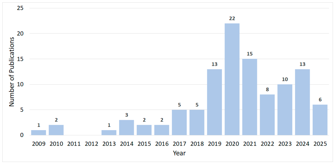
Figure 4.
Basic Block Diagram of a Noise Radar. (a) The reference is the digital record of the transmitted code. (b) The reference is the record of the transmitted signal at the antenna port. ADC = Analog-to-Digital-Converter. DAC = Digital-to-Analog-Converter.
Figure 4.
Basic Block Diagram of a Noise Radar. (a) The reference is the digital record of the transmitted code. (b) The reference is the record of the transmitted signal at the antenna port. ADC = Analog-to-Digital-Converter. DAC = Digital-to-Analog-Converter.
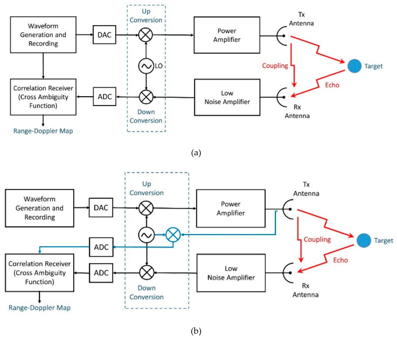
Figure 5.
Basic Block Diagram of the waveform generator for a modern Noise Radar. PRN: Pseudo Random Number, ZMNL: Zero-Memory Non-Linearity. PAPR: Peak-to-Average Power Ratio.
Figure 5.
Basic Block Diagram of the waveform generator for a modern Noise Radar. PRN: Pseudo Random Number, ZMNL: Zero-Memory Non-Linearity. PAPR: Peak-to-Average Power Ratio.
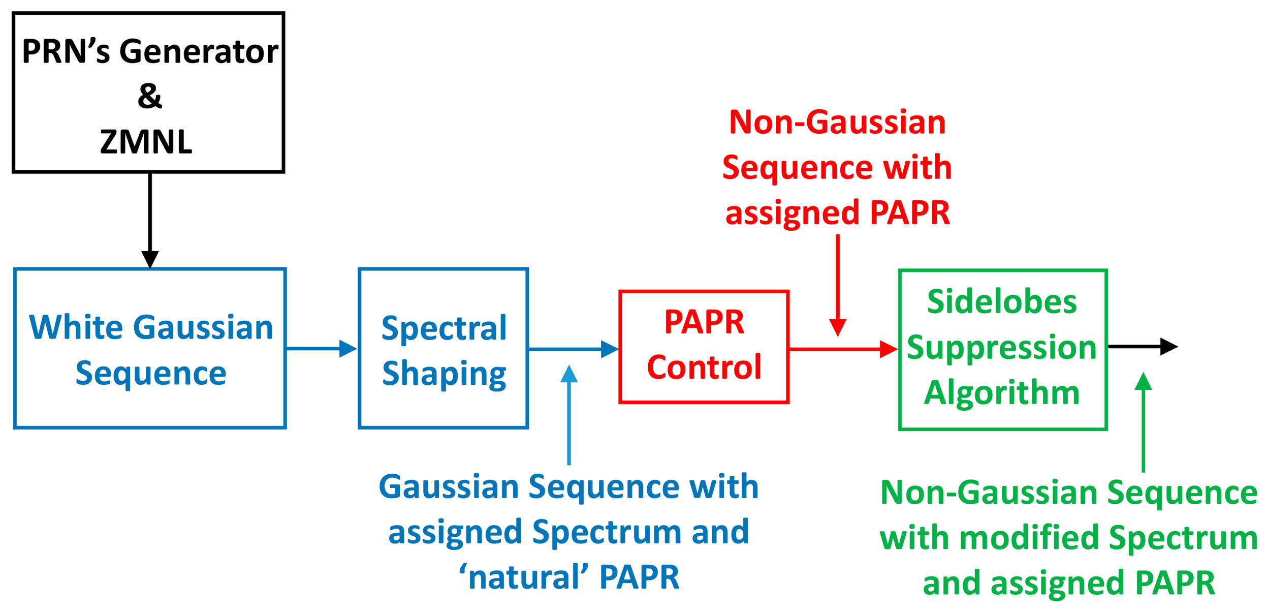
Figure 6.
Average background photons per unit mode, Eq. (2), versus the frequency (up to infrared radiation, 100 THz) for different values of . Dashed lines show the first order approximation.
Figure 6.
Average background photons per unit mode, Eq. (2), versus the frequency (up to infrared radiation, 100 THz) for different values of . Dashed lines show the first order approximation.
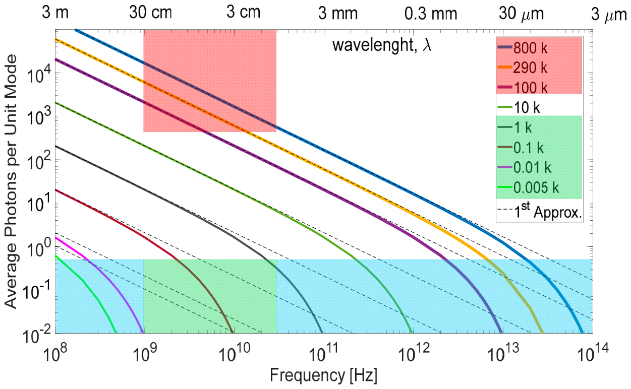
Figure 7.
Frequency value,
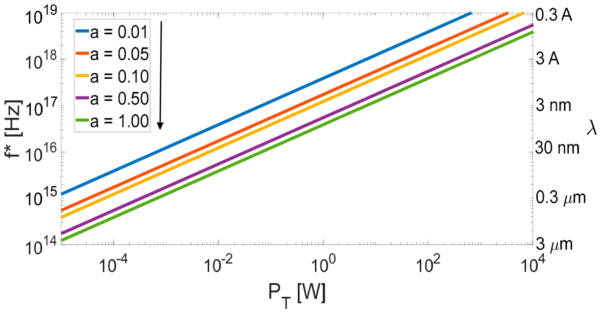
Figure 8.
Comparison between the Maximum range for Noise Radar, Eq. (1), and Quantum Radar, Eq. (8), at X-band vs time-duration
Figure 8.
Comparison between the Maximum range for Noise Radar, Eq. (1), and Quantum Radar, Eq. (8), at X-band vs time-duration
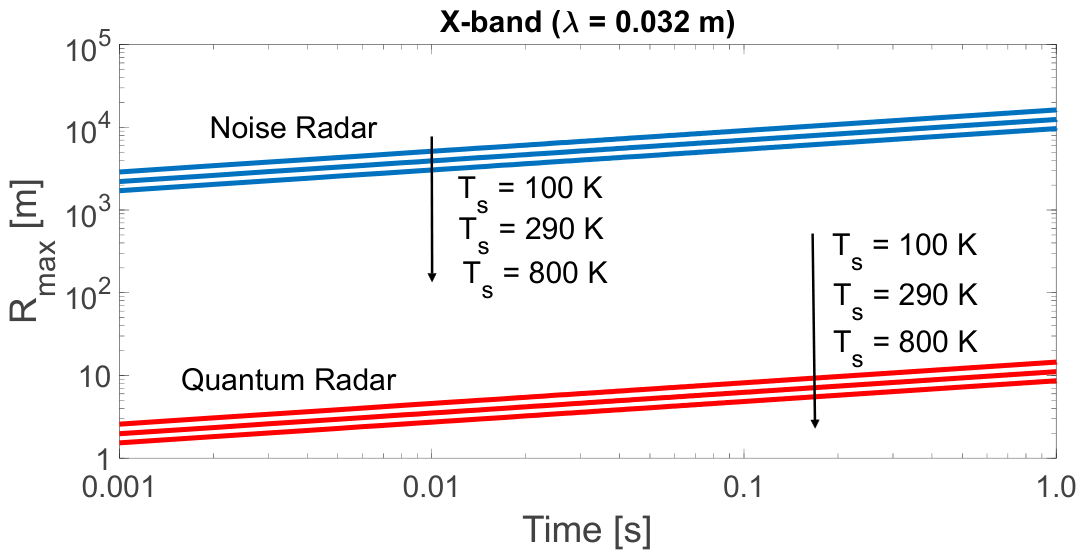
Figure 9.
Comparison between the Maximum range for Noise Radar, Eq. (1), and Quantum Radar, Eq. (8), at L-band vs time-duration
Figure 9.
Comparison between the Maximum range for Noise Radar, Eq. (1), and Quantum Radar, Eq. (8), at L-band vs time-duration
Disclaimer/Publisher’s Note: The statements, opinions and data contained in all publications are solely those of the individual author(s) and contributor(s) and not of MDPI and/or the editor(s). MDPI and/or the editor(s) disclaim responsibility for any injury to people or property resulting from any ideas, methods, instructions or products referred to in the content. |
© 2026 by the authors. Licensee MDPI, Basel, Switzerland. This article is an open access article distributed under the terms and conditions of the Creative Commons Attribution (CC BY) license (http://creativecommons.org/licenses/by/4.0/).
Copyright: This open access article is published under a Creative Commons CC BY 4.0 license, which permit the free download, distribution, and reuse, provided that the author and preprint are cited in any reuse.