

Submitted:
09 May 2026
Posted:
11 May 2026
You are already at the latest version
Abstract
An anti-contamination agent (Zn/Al–ATMP–LDH) has been synthesized by intercalation and used to correct the abnormal thickening and related operational risks caused by contact contamination between drilling fluids and cement slurries during high-temperature/high-pressure cementing. Experimental results have shown that the agent is chemically stable and exhibits good compatibility with conventional spacer-fluid additives. When compared with the direct addition of amino tris(methylenephosphonic acid) (ATMP), confining ATMP within a layered double hydroxide (LDH) markedly mitigates the retarding effect. At a dosage exceeding 0.3 wt%, the compressive strength of cement stone increases from 0 to 32.84 MPa following curing at 90 °C for 1 day, and continues to develop steadily after 7 days. Following conditioning at 187 °C, 145 MPa and 120 min, the spacer system formulated using the proposed agent as the core component serves to enhance the rheology of the mixed slurry via synergistic adsorption-regulation-dispersion stabilization-controlled release. The mixed slurry maintains stable rheological properties before and after aging with no uncontrolled thickening. When mixing the cement slurry and drilling fluid at a 7:3 volume ratio, the slurry consistency exceeds 60 Bc within 1 h, failing to meet operational requirements. In contrast, the mixed slurry containing the anti-contamination spacer (cement slurry:drilling fluid:spacer = 7:2:1) exhibits a thickening time greater than 300 min, and has been successfully applied in field cementing operations in a well in the Gaomo area.
Keywords:
anti-contamination agent
; drilling fluid
; spacer fluid
; layered double hydroxide (LDH)
; compatibility
1. Introduction
With the development of deep, ultra-deep, and high-temperature/high-pressure oil and gas resources, oil-based drilling fluids (OBDFs) are widely used in complex formations, offering effective inhibitive capacity, lubricity, and thermal stability [1,2,3,4]. The application of OBDFs is critical in maintaining wellbore stability and reducing downhole accident risks in high-temperature/high-pressure wells and complicated hole sections. However, during casing running and cementing operations, contact between drilling fluid and cement slurry is unavoidable, resulting in serious contamination. This issue is now a key technical challenge that impacts the safe and stable application of OBDFs [5].
When cement slurry comes into contact with drilling fluid, the free water associated with the slurry, and the Ca2+ and OH- generated during cement hydration, can significantly alter the internal aqueous OBDF chemical environment. This serves to destabilize the invert emulsion structure and causes a series of adverse effects, including reduced electrical stability, deteriorating rheological properties, and increased high-temperature/high-pressure fluid loss [6,7,8,9,10]. Under high-temperature/high-pressure conditions, these contamination effects are more pronounced, contributing to drilling-fluid performance failure and possibly triggering engineering risks such as pipe sticking and wellbore instability [11,12]. Consequently, the development of efficient and stable anti-contamination technologies is crucial to ensure drilling safety in high-temperature/high-pressure wells.
Current studies dealing with the contamination of OBDFs and cement slurries have focused on mitigating the effects by increasing emulsifier dosage, introducing wetting agents, adding polymer dispersants, or utilizing chelating agents [13,14,15]. These approaches are largely based on a “contamination tolerance” strategy. Free chelating agents or phosphonate additives may complex strongly with or adsorb on the cement slurry, resulting in abnormally prolonged thickening times or severe set-retardation risks [16,17,18,19]. Moreover, conventional polymers and surfactants are prone to thermal degradation or “salting-out” at elevated temperatures, which impedes sustained and stable interfacial regulation in the mixed-slurry section [19,20,21,22]. The development of a novel anti-contamination material that combines high thermal stability with long-lasting performance has assumed increased importance as a critical issue that must be addressed for oil-based drilling fluids [23,24,25,26,27,28].
Layered double hydroxides (LDHs) exhibit positively charged host layers, exchangeable interlayer anions, high specific surface area, and structurally tunable frameworks. The application of LDHs enables the adsorption and immobilization of anionic contaminants, regulation of ionic strength, and stabilization of dispersed systems [29,30,31,32,33]. In this study, a novel anti-contamination agent is proposed based on a zinc-aluminum hydrotalcite-like layered structure (Zn–Al LDH). By combining coprecipitation with ion exchange, amino tris(methylenephosphonic acid) (ATMP) is introduced into the hydroxide interlayer galleries. The structure and composition of the anti-contamination agent are characterized by x-ray diffraction (XRD), Fourier transform-infrared (FT-IR), thermogravimetric/differential thermogravimetric (TG/DTG), and particle-size analysis. Changes in the compressive strength of cement stone before and after the addition of the anti-contamination agent are evaluated using a single-factor method. In addition, compatibility experiments are conducted to assess the rheological behavior and thickening time of mixed slurries containing the anti-contamination agent, cement slurry, and drilling fluid, in order to meet the requirements of field application.
The proposed anti-contamination agent can regulate the migration of Ca2+ and OH- by ion exchange with a synergistic release mechanism when the cement slurry comes into contact with the drilling fluid, impeding the chemical interference of the cement slurry with the oil-based drilling fluid system [14,15,16,17,18,19]. The findings of this study offer a new material design strategy and a mechanistic understanding of contamination control in oil-based drilling fluids. Moreover, the developed agent has been successfully applied in field operations in a well located in the Gaomo block.
2. Materials and Methods
2.1. Materials
The materials used in this study included Jiahua G-grade oil well cement, quartz sand, iron ore powder, silica fume, barite, and composite whiskers. The additives used in the oil well cement system were SDP-1, SD210, SD130, SD52, SD77, and SD35. The cement slurry formulation was as follows: 100 wt% Jiahua G-grade cement + 31.7 wt% quartz sand + 1.12 wt% iron ore powder + 2.43 wt% silica fume + 2.43 wt% SDP-1 + 4.86 wt% SD77 + 1.46 wt% SD35 + 7.31 wt% composite whiskers + 4.39 wt% SD210 + 12.19 wt% SD130 + 0.48 wt% SD52 + 63.9 wt% water; the slurry had a density of 2.32 g/cm3. The oil-based drilling fluid was collected from an on-site drilling operation in the Sichuan–Chongqing region. The fluid composition and properties were as follows: 0.2% sand content; 30% solids content; 4% oil-phase content; 17.16 g/L bentonite; 38,000 mg/L Cl⁻; 400 mg/L Ca2+; 8% plugging agent content; density = 2.28 g/cm3.
The materials used in the preparation of the anti-contamination agent included amino tris(methylenephosphonic acid) (ATMP), zinc nitrate hexahydrate (Zn(NO3)2·6H2O), aluminum nitrate nonahydrate (Al(NO3)3·9H2O), sodium hydroxide (NaOH), sodium nitrate (NaNO3), and ethylene glycol. All of the chemicals were purchased from Chengdu Kelong Chemical Reagent Factory and were of analytical grade.
2.2. Experimental Method
The cement slurries were prepared in accordance with GB/T 19139–2012 (Test Methods for Oil Well Cement). Mixed slurry compatibility tests were conducted using a high-temperature/high-pressure consistometer (TG-8040DA), following the thickening-time procedure specified in the standard. Thickening tests were conducted by mixing the cement slurry, drilling fluid, and spacer fluid at different mass ratios using an additional high-temperature/high-pressure consistometer (OWC-9308, Institute of Applied Technology, Shenyang Institute of Aeronautical Industry). The mixed slurries were cured in an atmospheric consistometer (OWC-9350A, Shenyang Aeronautical Research Institute). Rheological properties before and after curing were assessed using a six-speed rotational viscometer (ZNN-06B, Qingdao Tongchun Petroleum Instrument Co., Ltd.). The compressive strength of the cured cement stone was determined using a compression testing machine (TYE-300, Jianyi Instrument Machinery Co., Ltd.).
An X-ray diffractometer (DX-2700, Dandong Haoyuan Instrument Co., Ltd.) was employed to identify the characteristic diffraction peaks of the hydrotalcite-like material and confirm successful synthesis. Fourier transform-infrared spectroscopy (FT-IR, WQF-520, Beijing Rayleigh Analytical Instrument Co., Ltd.) was utilized to identify the functional groups associated with the hydrotalcite precursor and the intercalated hydrotalcite-type anti-contamination agent, in order to verify successful incorporation of the anti-contamination molecules in the interlayer structure. The particle size of the synthesized anti-contamination agent was measured using a laser particle size analyzer (Mastersizer 2000, Malvern Instruments Ltd., UK). Thermogravimetric-differential thermogravimetric analysis (TG-DTG, SDTA85, Mettler Toledo, Switzerland) and scanning electron microscopy (SEM, ZEISS EVO MA15, Carl Zeiss, Germany) were used to evaluate thermal stability and microstructural morphology of the anti-contamination agent.
2.3. Preparation of the Anti-Contamination Agent
Firstly, 18.73 g Zn(NO3)2·6H2O and 7.87 g Al(NO3)3·9H2O were dissolved in deionized water and diluted to a final volume of 200 mL. The resulting solution is denoted as solution M. In addition, 17.00 g NaNO3 was dissolved in 250 mL deionized water. When the solution had cooled, 16.00 g NaOH was slowly added until fully dissolved, and the final volume was adjusted to 400 mL, yielding mixed solution B that contained 1.0 mol/L NaOH and 0.5 mol/L NaNO3.
Next, 200 mL deionized water was added to a three-neck flask and heated to 70 °C. Solutions M and B were simultaneously added dropwise into the flask. The pH of the system was continuously monitored during co-precipitation and maintained in the 9.5–10 range. The coprecipitation reaction proceeded for 7 h. The suspension was cooled to room temperature, vacuum-filtered, and washed with deionized water until neutral. The resulting solid was freeze-dried and then dried in an oven at 60 °C for 24 h. After grinding, a white powder (Zn–Al–NO3–LDH) was obtained.
The ATMP was dissolved in deionized water, and the pH of the solution adjusted to 9 with NaOH. A known amount of Zn/Al–NO3–LDH was dispersed in the ATMP solution and stirred at 55 °C for 5 h, allowing a gradual replacement of interlayer NO3- ions by ATMP through intercalation. Following the reaction, the solid product was separated by centrifugation, repeatedly washed with deionized water until neutral, dried in an oven, and then ground and sieved to obtain the anti-contamination agent (Zn/Al–ATMP–LDH).
As shown in Figure 1, the prepared anti-contamination agent exhibits a layered stacked structure with clear particle boundaries and relatively smooth edges. The particle-size analysis has established that the majority of particles are distributed in the 1–10 μm range, indicating that the anti-contamination agent is principally composed of fine micro/nanoscale particles.
3. Results and Discussion
3.1. Preparation and Characterization of the Anti-Contamination Agent
3.1.1. FT-IR Analysis
The FT-IR spectra of the anti-contamination agent and precursor are shown in Figure 2. It can be seen that both samples exhibit absorption features that are typical of LDH materials. The broad band at 3480 cm-1 is assigned to the O–H stretching vibration of hydroxyl groups in the host layers and interlayer water molecules, whereas the band at 1643 cm-1 corresponds to the H–O–H bending vibration of water molecules. The absorption band in the 607–620 cm-1 range is attributed to Zn/Al–O framework vibration, indicating that the layered double hydroxide structure is stable.
In the case of Zn/Al–NO3–LDH, characteristic nitrate absorption bands were recorded at 1394 and 620 cm-1, and relatively strong absorption peaks are also observed near 1132 and 1078 cm-1, confirming the intercalation characteristics of the inorganic anion system. In contrast, the spectrum of Zn/Al–ATMP–LDH shows strong characteristic P–O vibration bands at 1087 and 930 cm-1, whereas the characteristic peak at 1394 cm-1 is significantly weaker. These changes serve to indicate that ATMP was successfully introduced into the interlayer space and exchanged with NO3-. The observed variation in the characteristic peaks confirms that Zn/Al–NO3–LDH was effectively modified by ATMP ion-exchange intercalation.
3.1.2. XRD Analysis
The XRD patterns of the anti-contamination agent and precursor are presented in Figure 3. In the case of Zn–Al–NO3–LDH, a series of basal reflection peaks, including (003), (006), and (009), appear in the low-angle region. In addition, non-basal diffraction peaks, such as (015), (018), and the (110) and (113) reflections near 60° are present in the medium- and high-angle regions. These results indicate that the sample possesses a well-ordered layered stacking structure and good crystallinity, which are characteristic features of LDH phase.
When compared with Zn–Al–NO3–LDH, Zn–Al–ATMP–LDH retained the basal (003), (006), and (009) reflections but the associated peaks are shifted to lower diffraction angles. This shift can be attributed to the replacement of the relatively small interlayer NO3- ions by ATMP containing multiple phosphonic acid groups, which serve to significantly expand the interlayer spacing. In addition, the intensities of the non-basal (015) and (018) peaks are markedly weakened and even difficult to distinguish following ATMP modification. This suggests that the intercalation process lowered the stacking order of the LDH layers, decreasing the crystallite size. These changes further confirm that ATMP was successfully inserted in the interlayer galleries.
3.1.3. Thermal Stability
The thermogravimetric results for the anti-contamination agent and precursor are shown in Figure 4. Both samples exhibit the typical thermal response associated with LDH materials. The Zn/Al–NO3–LDH weight-loss peaks, at approximately 105, 201, and 381 °C, correspond to the removal of interlayer water (16.66%), dehydroxylation of the host layers and decomposition of interlayer NO3- anions (27.61%), which lead to the collapse of the layered structure.
The low-temperature weight loss for Zn/Al–ATMP–LDH is decreased by 3.61%, indicating that the intercalation of ATMP alters the water-binding characteristics, reducing the amount of bound water. In addition, the weight-loss peaks in the medium- and high-temperature regions are broadened and shifted slightly to lower temperatures, suggesting that intercalation serves to reduce the stacking order of the layers, increasing the microstrain in the structure so that dehydroxylation and ATMP release occur more readily. The total weight loss following ATMP intercalation decreased from 44.26% to 36.97%, where the weight loss in the high-temperature region decreased from 5.69% to 3.77%. These results indicate that the introduction of ATMP improves stability at elevated temperatures.
3.2. Effect of the Anti-Contamination Agent on the Compressive Strength of Cement Stone
Cement slurries containing different dosages of the agent were cured at 90 °C to evaluate the effect of the anti-contamination agent on cement stone; the results are presented in Figure 5. It is evident that the incorporation of ATMP markedly inhibits the early compressive strength development. When the dosage exceeded 0.3 wt%, the compressive strength following curing at 90 °C for 1 day dropped to 0 MPa. Although the strength shows a slight recovery after 7 days of curing, it still fails to meet field application requirements. This response indicates that free ATMP exerts a strong retarding effect with respect to cement hydration.
In contrast, the incorporation of Zn/Al–ATMP–LDH served to significantly enhance strength development. The early compressive strength of cement stone increased from 17.76 MPa to 28.92–34.66 MPa, where the maximum value (40.81 MPa) was attained after 3 days of curing. Moreover, following curing for 7 days, the compressive strength of all Zn/Al–ATMP–LDH-containing samples is higher than that of the neat cement slurry. These results suggest that the intercalation of ATMP in the LDH structure reduces the free-state concentration. During cement hydration, ATMP is gradually released as opposed to a sudden direct contact with the cement slurry, weakening Ca2+ complexation during hydration. As the prepared Zn/Al–ATMP–LDH particles are formed at the nano-scale range, this provides more nucleation sites and fills the pores in the cement stone, promoting hydration products with microstructure densification. As a result, the material exhibits a pronounced increase in early strength and a stable increase in strength at later curing ages.
3.3. Compatibility of the Anti-Contamination-Agent-Containing Spacer Fluid Under Different Conditions
3.3.1. Compatibility of the Anti-Contamination Spacer Fluid
The prepared agent was combined with other spacer-fluid additives to test chemical stability in formulating an anti-contamination spacer fluid. The changes to the rheological properties of the spacer fluid were tested after aging at 187 °C and 145 MPa for 3 h; the results are presented in Table 2 and Table 3. The experimental data establish that stable viscometer readings and rheological parameters were obtained for all the systems before and after aging, with no obvious thickening or gelation. This indicates that, after compounding with different dispersants, fluid-loss additives, and suspension stabilizers, the anti-contamination agent maintains an overall controllable rheology response with no evidence of incompatibility.
Although the consistency of different spacer-fluid formulations fluctuated during aging, the associated curing curves exhibit a gradual decline with increasing aging time. A comparison of the apparent viscosity and yield point of the spacer fluids before and after aging demonstrates that the aged spacer fluids retain suitable pumpability and structural stability. The results confirm that the anti-contamination agent shows good compatibility with other spacer-fluid additives.

Table 1.
Compatibility of the anti-contamination agent in spacer fluid systems.
| Spacer fluid formulation | Dispersant | Fluid-Loss Additive | Suspension Stabilizer | Aging Conditions | Aging Time / min |
|---|---|---|---|---|---|
| Formulation 1 | D1 | L1 | S1 | 187 °C, 145 MPa, 120 min | 180 |
| Formulation 2 | D2 | L2 | S2 | 187 °C, 145 MPa, 120 min | 180 |
| Formulation 3 | D1 | L2 | S3 | 187 °C, 145 MPa, 120 min | 180 |
| Formulation 4 | D2 | L1 | S4 | 187 °C, 145 MPa, 120 min | 180 |
Note: The base spacer-fluid formulation was water + 4%–6% suspension stabilizer + 5% anti-contamination agent + 2%–3% dispersant + 0.2%–0.6% fluid-loss additive + 10% micro-manganese + 50% barite.
Figure 6.
Spacer fluid curing curves.
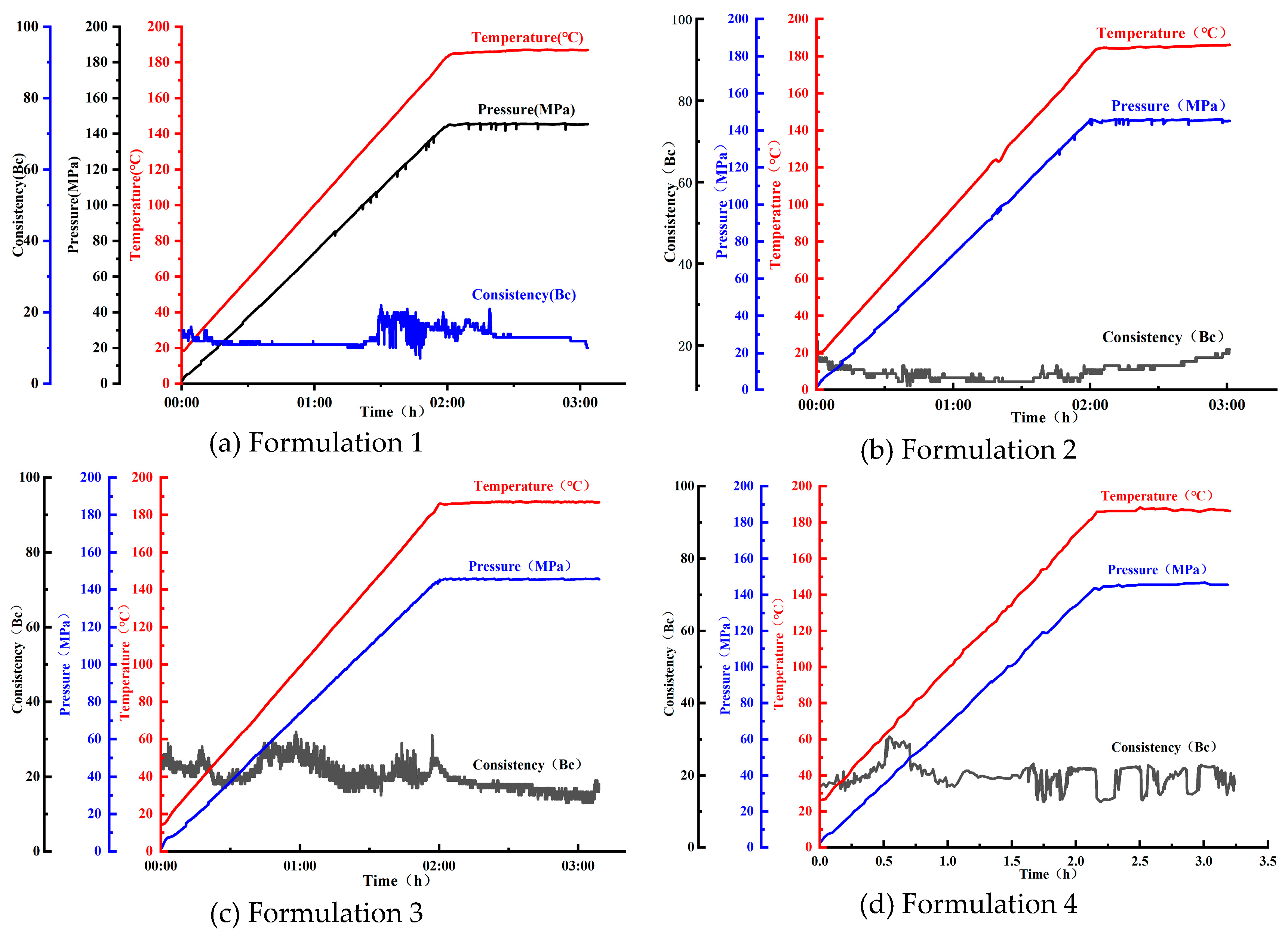
Table 2.
Rheological properties of the anti-contamination spacer fluid before aging.
| Spacer fluid formulation | Rotational speed (r/min) | AV/mPa·s | YP/lb/100 ft2 | K/Pa·sn | n | |||||
|---|---|---|---|---|---|---|---|---|---|---|
| 3 | 6 | 100 | 200 | 300 | 600 | |||||
| Formulation 1 | 6 | 9 | 54 | 78 | 96 | 140 | 70 | 52 | 1.87 | 0.52 |
| Formulation 2 | 2 | 4 | 25 | 40 | 52 | 81 | 40.5 | 23 | 0.42 | 0.67 |
| Formulation 3 | 5 | 10 | 31 | 42 | 51 | 74 | 37 | 28 | 1.54 | 0.45 |
| Formulation 4 | 2 | 4 | 12 | 21 | 31 | 50 | 25 | 12 | 0.86 | 0.07 |
Table 3.
Rheological properties of the anti-contamination spacer fluid after aging.
| Spacer fluid formulation | Rotational speed(r/min) | AV/mPa·s | YP/lb/100 ft2 | K/Pa·sn | n | |||||
|---|---|---|---|---|---|---|---|---|---|---|
| 3 | 6 | 100 | 200 | 300 | 600 | |||||
| Formulation 1 | 7 | 9 | 61 | 94 | 122 | 174 | 87.0 | 70 | 1.22 | 0.63 |
| Formulation 2 | 2 | 3 | 31 | 57 | 80 | 136 | 68.0 | 24 | 0.19 | 0.86 |
| Formulation 3 | 1 | 2 | 11 | 19 | 29 | 49 | 24.5 | 9 | 0.06 | 0.88 |
| Formulation 4 | 1 | 2 | 10 | 17 | 25 | 43 | 21.5 | 7 | 0.07 | 0.83 |
3.3.2. Compatibility of the Anti-Contamination Spacer Fluid and Drilling Fluid at Different Temperatures
The rheological parameters of mixed slurries composed of drilling fluid and spacer fluid at different mixing ratios following aging at 50–150 °C for 24–48 h are presented in Table 4, Table 5 and Table 6. The results indicate that the mixed-slurry systems exhibit pseudoplastic behavior, where widespread irreversible thickening or solidification was not observed with increasing aging temperature or time. This response demonstrates that, following the incorporation of the anti-contamination agent, the spacer fluid shows good compatibility with the drilling fluid. At a drilling fluid-to-spacer fluid ratio of 7:3, the flow behavior index (n) under all the tested conditions falls within the 0.50-0.82 range, indicating suitable pumpability of the mixed slurry. When the drilling fluid-to-spacer fluid ratio is 3:7, the overall viscosity of the mixed slurry is higher, suggesting that increasing the proportion of spacer fluid enhances the carrier and suspension capacity of the system. Moreover, the slurry shows fluctuation patterns associated with shear-thinning under different aging conditions. In contrast, at a drilling fluid-to-spacer fluid ratio of 5:5, the mixed slurry is most sensitive to aging temperature and time, and abnormal thickening occurs after aging at 150 °C for 24 h (Figure 7). This effect is significantly alleviated when the aging is extended to 48 h, indicating that the thickening is reversible.
The results suggest that the observed compatibility of the mixed slurry after the addition of the anti-contamination agent may result from synergistic effects. The positively charged LDH layers can adsorb and capture anionic polymers, clay particles, and contaminating ions in the drilling fluid, impacting polymer bridging and particle flocculation. In addition, the ATMP groups can chelate multivalent metal ions such as Ca2+ and Mg2+, suppressing “salting-out” and crosslinking associated thickening due to the changes in ion concentration. The suspension-stabilizing components and weighting solids in the spacer fluid work in tandem to maintain a low-shear structural strength, preventing incompatibility features such as persistent high viscosity and high yield stress. The proposed anti-contamination spacer-fluid system exhibits good rheological stability and compatibility with the field drilling fluid over a range of mixing ratios and under high-temperature aging conditions.
3.4. Effect of the Anti-Contamination-Agent-Containing Spacer Fluid on the Thickening Time of the Cement Slurry and Drilling Fluid at Different Temperatures and Pressures
The anti-contamination performance of the spacer fluid after contact with the cement slurry and drilling fluid was evaluated under actual operating conditions. The anti-contamination spacer fluid was mixed separately with the drilling fluid and cement slurry at different volume ratios. Thickening tests were conducted at 187/128 °C and 145/60 MPa to determine if the mixed-slurry section can meet the thickening-time requirements for field operations. The results are shown in Figure 8, where it is evident that none of the mixed-slurry systems exhibited a sustained rapid increase or uncontrolled rise in consistency under the high-temperature/high-pressure conditions. The consistency remained low and fluctuated smoothly, with no evidence of undesirable flash setting or false setting in the mixed-slurry section. The results demonstrate that the anti-contamination spacer fluid exhibits good compatibility with the drilling fluid and the cement slurry. At a cement slurry:drilling fluid:spacer fluid volume ratio of 7:2:1, the consistency showed some fluctuation during the heating stage and then stabilized, with no flash setting or persistent abnormal thickening. When the drilling fluid:spacer fluid ratio was 5:5, a slight increase in consistency was observed in the mixed-slurry section, but the consistency subsequently reached a stable range, which is consistent with the results discussed above.
The thickening times of all the mixed-slurry systems exceed 300 min, which satisfies the requirements for safe field operation. These results confirm that, following the incorporation of the Zn/Al–ATMP–LDH anti-contamination agent, the spacer fluid can effectively suppress irreversible thickening caused by ionic disturbances and particle flocculation during mixing. The system maintained good compatibility and operational control under high-temperature/high-pressure conditions.
3.5. Mechanistic Features of the Anti-Contamination Agent
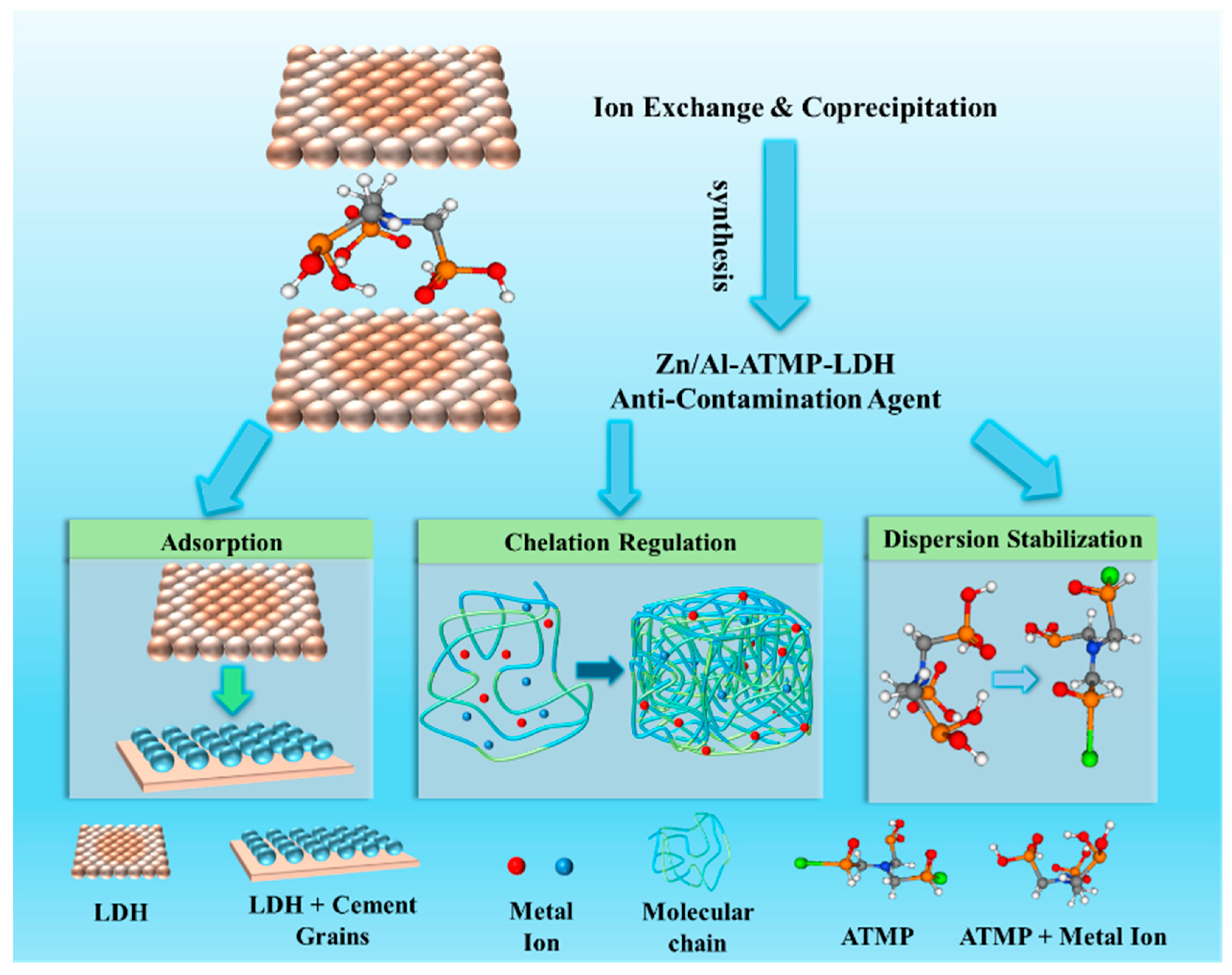
The Zn/Al–ATMP–LDH anti-contamination agent suppresses contact contamination between the cement slurry and drilling fluid via a synergism that involves adsorption, regulation, dispersion stabilization, and controlled release. The positively charged LDH layers possess a high anion-exchange capacity and surface adsorption capability, which enables a preferential adsorption of contaminating components in the drilling fluid, including anionic polymers, clay particles, and multivalent anions. This impacts polymer bridging and particle flocculation, reducing the risk of flash setting and abnormal thickening in the mixed-slurry section due to flocculation and agglomeration. Moreover, the intercalated ATMP contains phosphonic acid groups that can effectively chelate multivalent metal ions such as Ca2+ and Mg2+, alleviating abnormal thickening caused by sudden changes in ion concentration during mixing.
As a nanostructured material, Zn/Al–ATMP–LDH can provide nucleation sites and exert a filling effect in the system. When compared with free ATMP, the interlayer-confined ATMP exhibits a significantly reduced retarding side-effect on cement hydration. Consequently, the early compressive strength of the cement stone is enhanced, and the later strength development is also maintained. In addition, the anti-contamination agent can be effectively compounded with common spacer-fluid additives such as dispersants and suspension stabilizers, and displays high chemical stability. The spacer-fluid system can maintain pseudoplastic flow behavior and suitable pumpability under high-temperature/high-pressure conditions.
Figure 9.
Proposed anti-contamination mechanism.
4. Field Application
The anti-contamination spacer fluid formulated with Zn/Al–ATMP–LDH as the core component has been applied in a liner-hanger cementing operation in a well located in the Gaomo area. The field drilling fluid was oil-based, containing potassium-bearing sulfonates, plugging agents, barite, and other components. One of the major cementing challenges in this well is the severe contact contamination and poor compatibility between the drilling fluid and cement slurry. The field spacer-fluid formulation was: water + 4% S1 + 0.6% S2 + 0.6% S3 + 5% anti-contamination agent + 5% D1 + 10% micro-manganese + 48% barite. The operating temperature, pressure, and time were 187 °C, 145 MPa, and 120 min. Thickening tests were carried out on mixed slurries with volume ratios of cement slurry:drilling fluid:spacer fluid = 7:2:1 and cement slurry:drilling fluid = 7:3. The results are shown in Figure 10, where it can be seen that, when the cement slurry came into direct contact with the drilling fluid, the slurry consistency exceeded 60 Bc within 1 h, and the thickening curve exhibits a stepwise increase. The thickening time is far below the requirement for field operation. In contrast, at a cement slurry:drilling fluid:spacer fluid ratio of 7:2:1, the mixed slurry exhibited a relatively high initial consistency that gradually decreased to below 10 Bc as the test proceeded and the thickening time exceeded 300 min, fully meeting operational requirements. The thickening test involving the cement slurry mixed with spacer fluid also showed good compatibility, with a consistency below 10 Bc throughout the test and slurry stability established beyond 300 min.
These results confirm a successful liner cementing operation in this well. The proposed anti-contamination agent can be effectively applied under field conditions and may contribute significantly to future advanced cementing operations.
5. Conclusions
(1) In this study, an efficient anti-contamination agent (Zn/Al–ATMP–LDH) has been successfully prepared by coprecipitation and ion-exchange. The resultant agent shows good compatibility with common spacer-fluid additives, where the corresponding anti-contamination spacer fluid exhibits favorable rheological properties following aging at 187 °C and 145 MPa.
(2) The spacer fluid formulated with the proposed anti-contamination agent as the core component exhibits stable chemical properties and good compatibility following mixing with the cement slurry and drilling fluid. The mixed slurry aged at 187 °C and 145 MPa for 120 min maintains the requisite rheological properties. At an additive dosage of 5 wt%, the spacer fluid effectively alleviates contact contamination between the cement slurry and drilling fluid, meeting the requirements for field application.
(3) The anti-contamination agent suppresses contact contamination between the cement slurry and drilling fluid via synergistic adsorption, regulation, dispersion stabilization, and controlled release. When compared with the direct addition of ATMP, the interlayer confinement significantly reduces the strong retarding effect, ensuring an enhanced early compressive strength and stable later strength development of the cement stone.
(4) In field application at a well in the Gaomo block, the spacer fluid prepared using the proposed anti-contamination agent has effectively corrected the contact-contamination problem between the cement slurry and drilling fluid. The thickening time of the mixed slurry (cement slurry:drilling fluid = 7:3) increased from 60 min to greater than 300 min, and the system passed the field compatibility test, demonstrating viable practical application.
Author Contributions
Conceptualization, zhang song. and guan xi.; methodology, deng fei.; software, cheng xiaowei.; validation, deng fei., cheng xiaowei. and zhang song.; formal analysis, guan xi.; investigation, guan xi.; resources, zhang song.; data curation, zhang song.; writing—original draft preparation, deng fei.; writing—review and editing, deng fei.; visualization, deng fei.; supervision, zhang song.; project administration, guan xi.; funding acquisition, cheng xiaowei. All authors have read and agreed to the published version of the manuscript.
Acknowledgments
The authors are grateful for the funding support provided by the Science and Technology Project of CNPC Chuanqing Drilling Engineering Company Limited (Grant No. CQ2025B-6-5-3) and SWPU’s Advanced Cementitious Materials Research Center for its generous help in experiments.
Conflicts of Interest
The authors declare that they have no known competing financial interests or personal relationships that could have appeared to influence the work reported in this paper.
References
- Dennis, D. Improving compatibility of drilling fluid, completion fluid, and other well-treatment fluids for deepwater wells. J. Pet. Technol. 2011, 63(11), 65–66. [Google Scholar] [CrossRef]
- Soares, A. A.; Freitas, O. D. C. J.; Melo, A. D. M. D.; et al. Cement slurry contamination with oil-based drilling fluids. J. Pet. Sci. Eng. 2017, 15(8), 433–440. [Google Scholar] [CrossRef]
- Zhao, Z.; Li, M.; Zhang, Z.; et al. Experimental study on the factors affecting cement bond strength at the second interface of oil-gas well. J. Dispers. Sci. Technol. 2026, 47(4), 649–659. [Google Scholar] [CrossRef]
- Li, Z.; Ou, H. J.; Chen, S. Y.; et al. Effects of oil-based drilling fluid contamination on the performance of cement slurry. Drill. Prod. Technol. 2022, 45(1), 122–127. [Google Scholar]
- Li, Y. Z.; Liu, H. H.; Guo, Y. X.; et al. Research on new materials to improve the bonding strength and relieve contamination of the cement slurry with oil based muds. Mater. Sci. Forum 2016, 847, 510–518. [Google Scholar] [CrossRef]
- Yu, K.; Zhao, T.; Chen, L.; et al. Study on the construction of salt-responsive acrylamide-based polymer stabilized foam system and its drilling fluid performance. Colloids Surf. A Physicochem. Eng. Asp. 2026, 741, 140319. [Google Scholar] [CrossRef]
- Wei, Y. X. Mechanism of contact contamination between well cement slurry and drilling fluid. Chem. Manag. 2021, (4), 195–196. [Google Scholar]
- Feng, B.; He, L.; Ou, B.; et al. Effect of the solidifiable spacer fluid system on hydraulic sealing ability of the cement sheath-formation interface. ACS Omega 2026, 11(10), 16285–16293. [Google Scholar] [CrossRef]
- Li, X.; Wang, K.; Lu, Y.; et al. Compatibility and efficiency of hydrophilic/hydrophobic nano silica as rheological modifiers and fluid loss reducers in water-based drilling fluids. Geoenergy Sci. Eng. 2024, 234, 212628. [Google Scholar] [CrossRef]
- Li, Z. Y.; Liu, H. H.; Guo, X. Y.; et al. Effects of oil-based drilling-fluid components on cement slurry properties and the underlying mechanisms. Nat. Gas Ind. 2016, 36(3), 63–68. [Google Scholar]
- M, K.; A, D.; A, A.; et al. Recommendations for compatibility of different types of polymers with potassium/sodium formate-based fluids for drilling operations: An experimental comparative analysis. J. Mater. Sci. Eng. 2016, 5(6), 1–6. [Google Scholar] [CrossRef]
- Khan, I. M.; Das, P.; Mogira, A. M.; et al. Drilling mud contamination effect on wellbore cement strength: An experimental investigation. Heliyon 2024, 10(15), e35622. [Google Scholar] [CrossRef]
- Henry, E.; Ezekiel, D. S.; Ogboo, A. C. Evaluation of methyl ester sulphonate spacer fluid additive for efficient wellbore clean-up. Energy Geosci. 2022, 3(1), 73–79. [Google Scholar] [CrossRef]
- Yi, C. S.; Yong, M.; Hua, J. G.; et al. Study on the compatibility of acrylic acid-acrylamide-diethyldiallyl ammonium chloride copolymer with cement slurry in CO2 environment. ACS Omega 2024, 9(33), 35695–35702. [Google Scholar]
- Li, X. C.; Li, N.; Liu, R.; et al. Mechanism and preventive measures for contact contamination between organic-salt drilling fluids and cement slurries. Drill. Prod. Technol. 2019, 42(6), 102–104. [Google Scholar]
- Gautam, R.; Hazra, A.; Faujdar, P.; et al. Effect of size-controlled nanofluid on mechanical properties, microstructure, and rheological behavior of cement slurry for oil well cementing. ACS Omega 2024, 9(48), 47739–47755. [Google Scholar] [CrossRef]
- Huang, S.; Gao, Y.; Li, Z.; et al. Mitigating strategy and mechanism of cement slurry contamination caused by oil-based mud: Macro-micro experiments, molecular dynamics simulation and dissipative particle dynamics simulation. Constr. Build. Mater. 2024, 432(28), 136714. [Google Scholar] [CrossRef]
- McClure, J.; Khalfallah; et al. New cement spacer chemistry enhances removal of nonaqueous drilling fluid. J. Pet. Technol. 2014, 66(10), 32–35. [Google Scholar] [CrossRef]
- Lu, J.; Jiang, J.; Lu, Z.; et al. Pore structure and hardened properties of aerogel/cement composites based on nanosilica and surface modification. Constr. Build. Mater. 2020, 245, 118434. [Google Scholar] [CrossRef]
- Liu, X.; Nair, S.; Aughenbaugh, K.; et al. Mud-to-cement conversion of non-aqueous drilling fluids using alkali-activated fly ash. J. Pet. Sci. Eng. 2019, 182, 106242. [Google Scholar] [CrossRef]
- Li, Z.; Liu, H.; Guo, X.; et al. Contamination of cement slurries with oil based mud and its components in cementing operations. J. Nat. Gas Sci. Eng. 2016, 29, 160–168. [Google Scholar] [CrossRef]
- Liu, L. N.; Li, M.; Xie, D. B.; et al. A surfactant-based spacer fluid suitable for oil-based drilling fluids. Drill. Fluid Complet. Fluid 2017, 34(3), 77–80. [Google Scholar]
- Du, B. Z.; Tai, W.; Luo, W.; et al. Assembly and sustained-release behavior of allopurinol-intercalated Zn/Al–NO3–LDH composites. J. Inorg. Mater. 2011, 26(12), 1293–1298. [Google Scholar] [CrossRef]
- Q, Z.; D, L.; L, S.; et al. Effect of LDH on the dissolution and adsorption behaviors of sulfate in Portland cement early hydration process. Rev. Adv. Mater. Sci. 2022, 61(1), 381–393. [Google Scholar] [CrossRef]
- Cao, L.; Guo, J.; Tian, J.; et al. The ability of sodium metasilicate pentahydrate to adjust the compatibility between synthetic fluid loss additives and retarders applying in oil well cement. Constr. Build. Mater. 2018, 158, 835–846. [Google Scholar] [CrossRef]
- Nachiket, A.; Fernando, R.; Catalin, T.; et al. Experimental investigation of deterioration in mechanical properties of oil-based mud (OBM) contaminated API cement slurries and correlations for ultrasonic cement analysis. J. Pet. Sci. Eng. 2021, 205, 437. [Google Scholar] [CrossRef]
- Xu, D.; Guo, J.; Yuan, B.; et al. A minimum volume prediction of spacer based on turbulent dispersion theory: Model and example. Petroleum 2019, 5(4), 397–401. [Google Scholar] [CrossRef]
- Li, B.; Wail, S.; Shi, L.; et al. The early age hydration products and mechanical properties of autoclaved cement paste incorporating supplementary cementitious materials. Gels 2026, 12(2), 160. [Google Scholar] [CrossRef] [PubMed]
- Wang, J. X.; Hu, J. H.; Wang, C. Q.; et al. Cement slurry contamination by high-temperature, high-density drilling fluids in northeastern Sichuan and corresponding treatment. Drill. Fluid Complet. Fluid 2025, 42(3), 386–391. [Google Scholar]
- Shadravan, A.; Tarrahi; et al. Intelligent tool to design drilling, spacer, cement slurry, and fracturing fluids by use of machine-learning algorithms. SPE Drill. Complet. 2017, 32(2), 131–140. [Google Scholar] [CrossRef]
- Ting, Y. Z. M.; Yuan, W.; Sun, X.; et al. Influence of hydrophilic polymers contamination on hydration, hardened properties, and microstructure of cement paste. J. Build. Eng. 2026, 119, 115246. [Google Scholar] [CrossRef]
- Dang, H. D.; Gao, F.; He, Y. J.; et al. Research and application of cement plugging techniques in evaporite bed of piedmont tectonic belt of the Tarim Basin. Adv. Mater. Res. 2013, 2695(807), 2634–2638. [Google Scholar] [CrossRef]
- Li, M.; Ou, H.; Li, Z.; et al. Contamination of cement slurries with diesel-based drilling fluids in a shale gas well. J. Nat. Gas Sci. Eng. 2015, 27, 1312–1320. [Google Scholar] [CrossRef]
Figure 1.
Morphology and particle size distribution of the anti-contamination agent.
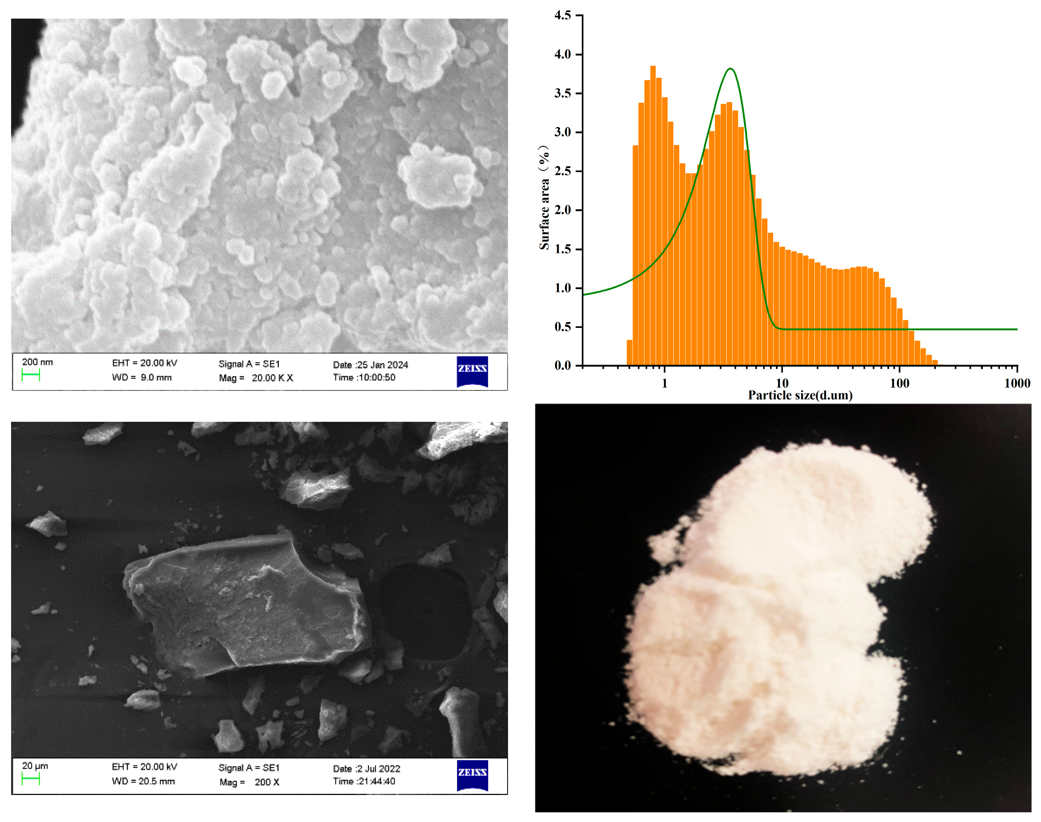
Figure 2.
FT-IR spectra of the anti-contamination agent.
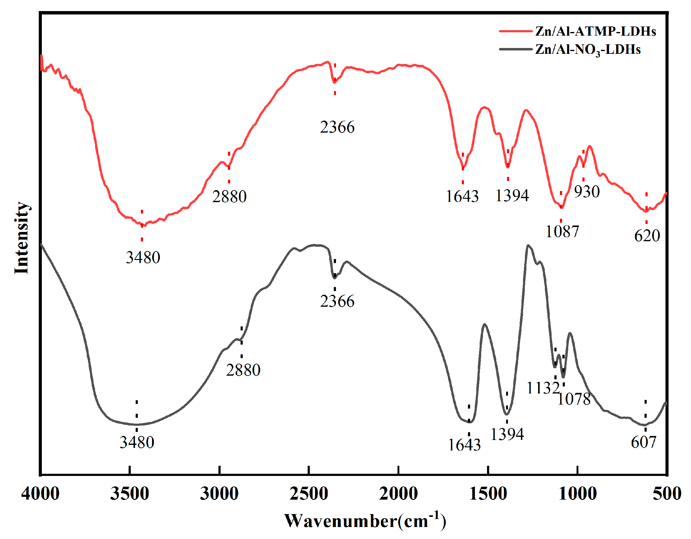
Figure 3.
XRD patterns of the anti-contamination agent and precursor.
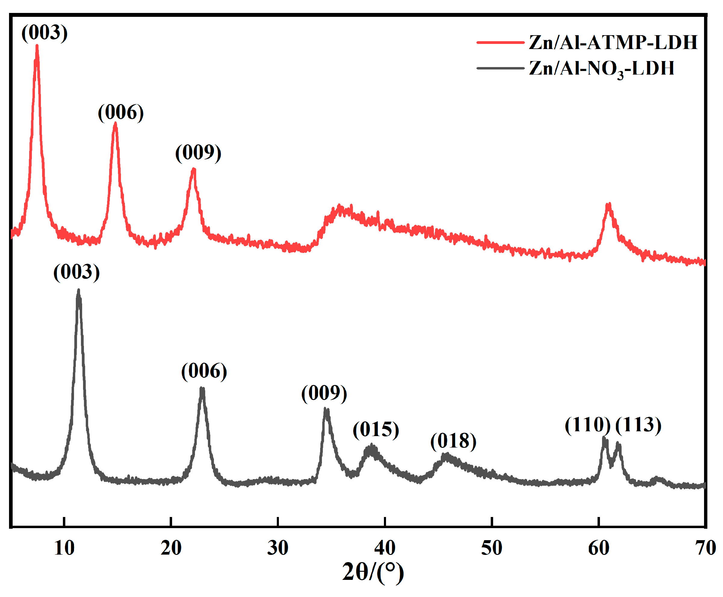
Figure 4.
TG-DTG profiles for the anti-contaminant agent.
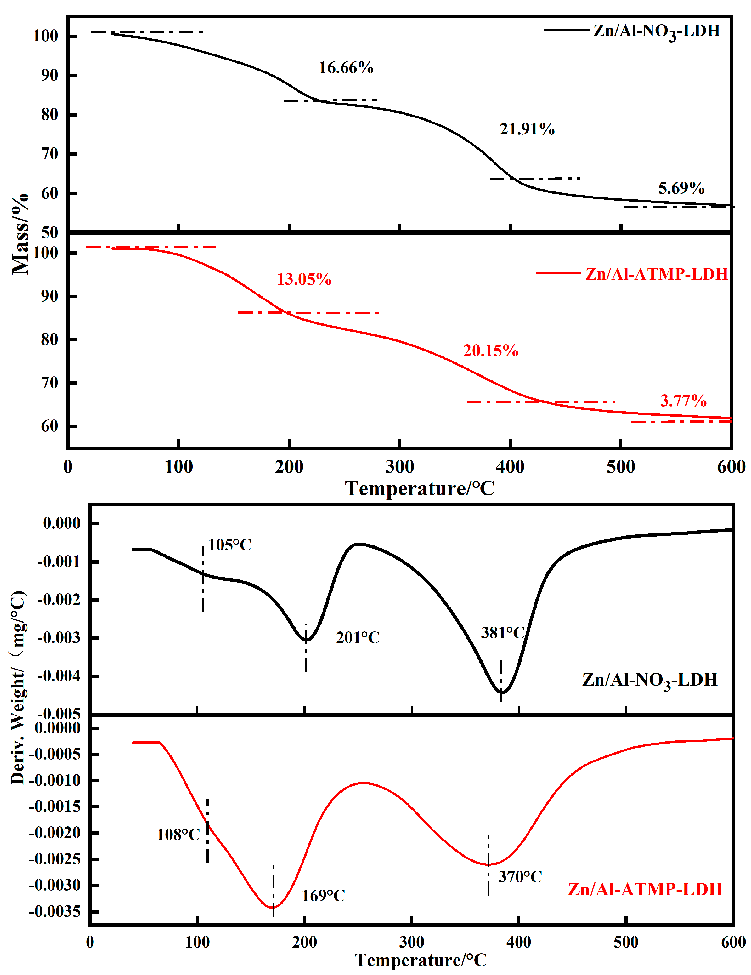
Figure 5.
Cement stone compressive strength analysis; (a) temporal variation of strength with the direct addition of ATMP; (b) temporal variation of strength following the incorporation of Zn/Al-ATMP-LDH.
Figure 5.
Cement stone compressive strength analysis; (a) temporal variation of strength with the direct addition of ATMP; (b) temporal variation of strength following the incorporation of Zn/Al-ATMP-LDH.
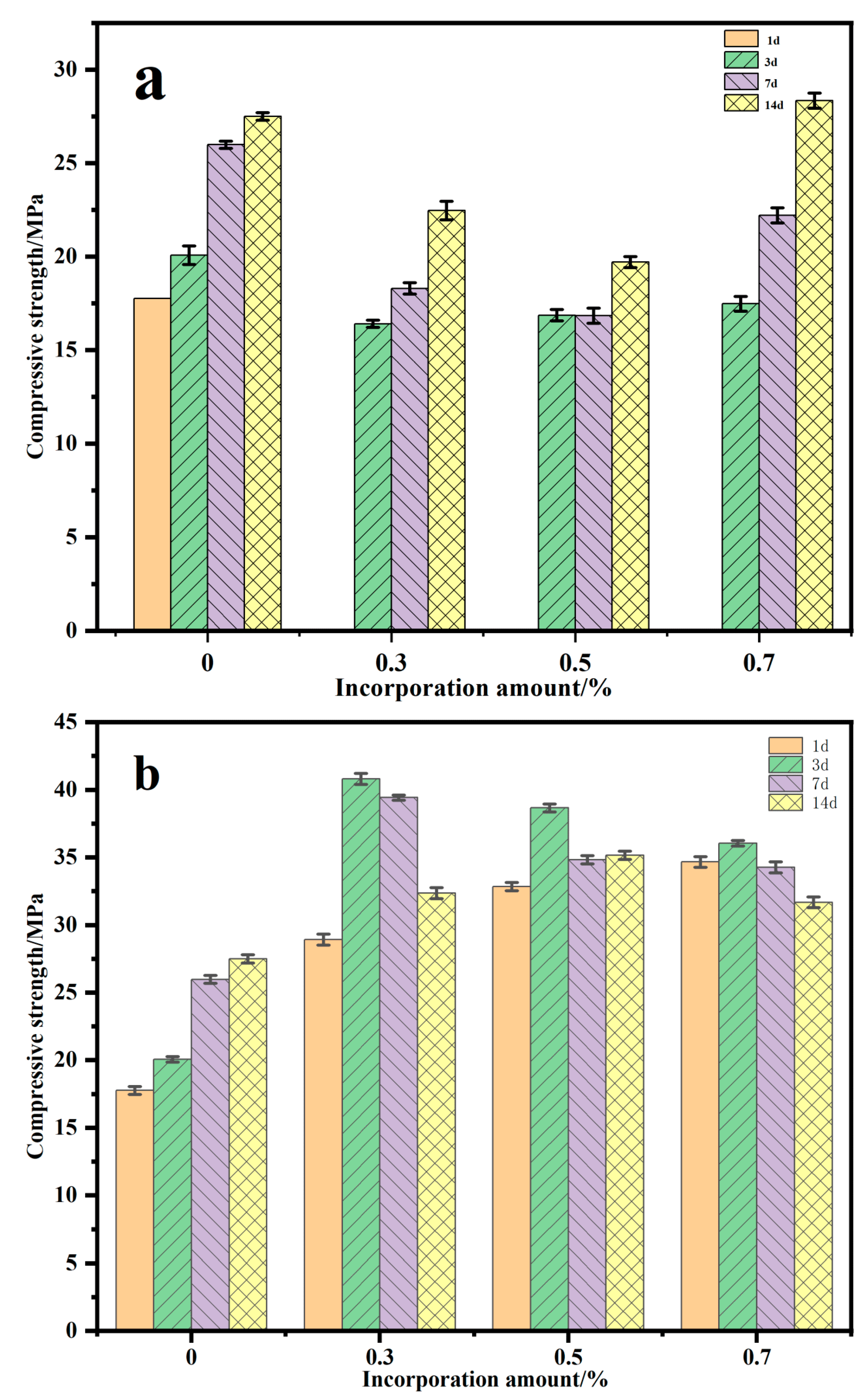
Figure 7.
Images showing the changes in morphology for the mixed-slurry section after aging.
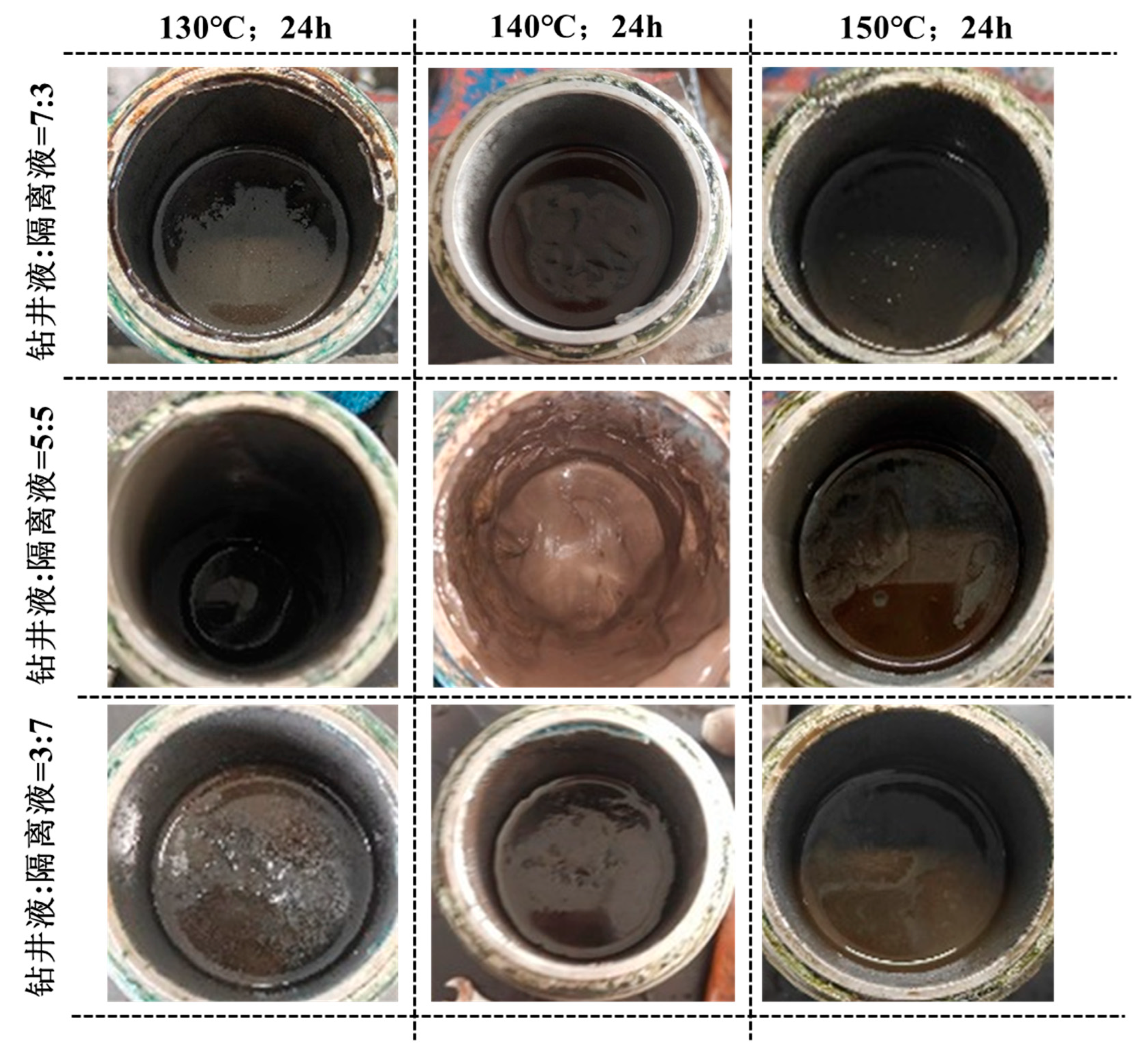
Figure 8.
Thickening curves for the mixed-slurry section at different volume ratios of cement slurry, drilling fluid, and spacer fluid.
Figure 8.
Thickening curves for the mixed-slurry section at different volume ratios of cement slurry, drilling fluid, and spacer fluid.
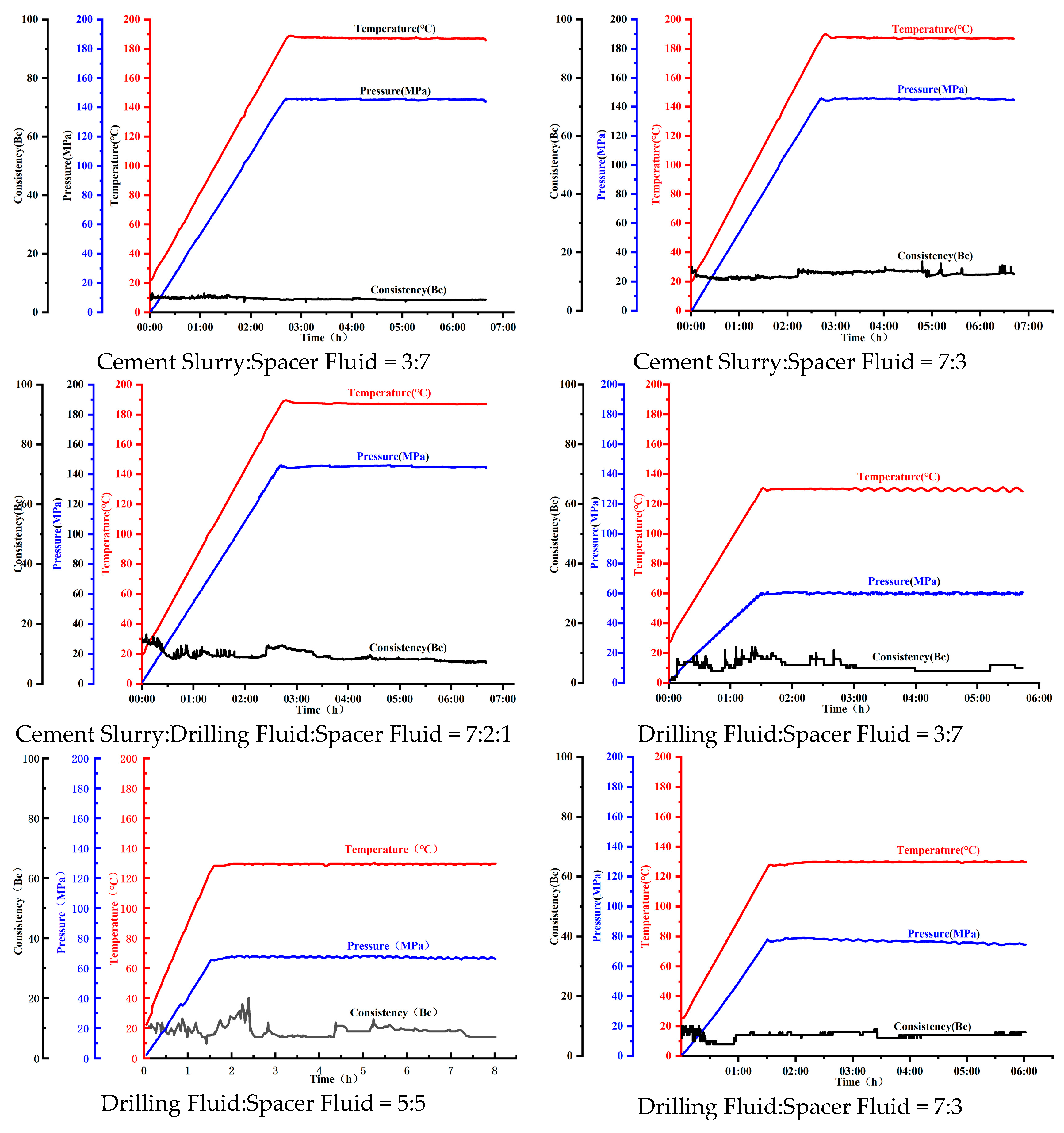
Figure 10.
Field contamination experimental results.
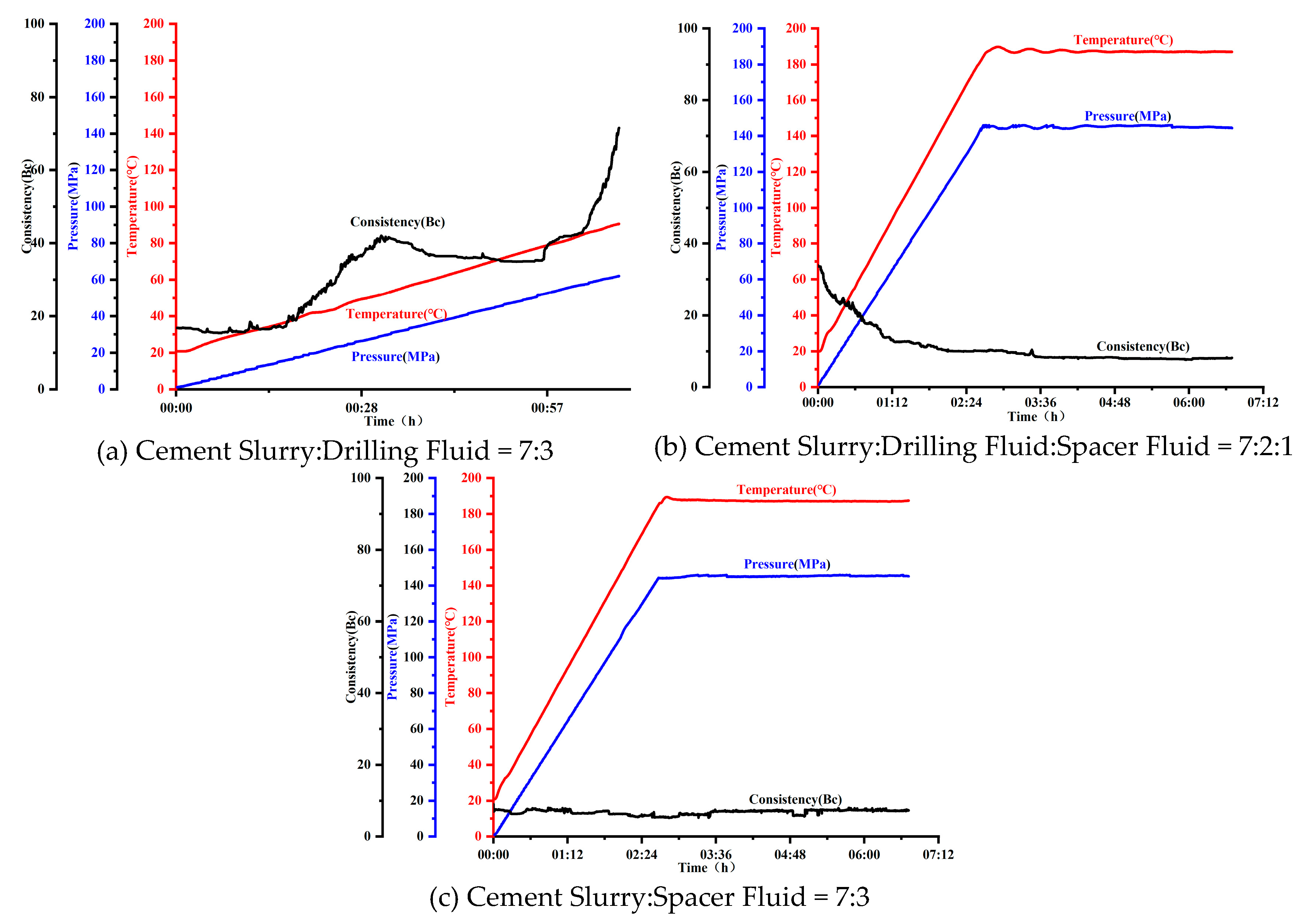
Table 4.
Rheological test results for the mixed slurry with a drilling fluid:spacer fluid ratio of 7:3 at different temperatures.
Table 4.
Rheological test results for the mixed slurry with a drilling fluid:spacer fluid ratio of 7:3 at different temperatures.
| Drilling Fluid:Spacer Fluid = 7:3 | Rotational speed (r/min) | AV/mPa·s | YP/lb/100 ft2 | K/Pa·sn | n | |||||
|---|---|---|---|---|---|---|---|---|---|---|
| 3 | 6 | 100 | 200 | 300 | 600 | |||||
| 50°C | 8 | 11 | 37 | 57 | 75 | 120 | 60 | 30 | 0.69 | 0.64 |
| 130°C 24h | 6 | 10 | 45 | 67 | 78 | 126 | 63 | 30 | 1.76 | 0.50 |
| 130°C 48h | 4 | 5 | 32 | 55 | 79 | 126 | 63 | 32 | 0.24 | 0.82 |
| 140°C 24h | 9 | 11 | 39 | 74 | 83 | 142 | 71 | 24 | 0.58 | 0.69 |
| 140°C 48h | 8 | 15 | 36 | 65 | 78 | 116 | 58 | 40 | 0.49 | 0.70 |
| 150°C 24h | 3 | 7 | 34 | 56 | 63 | 93 | 46.5 | 33 | 0.97 | 0.56 |
| 150°C 48h | 4 | 7 | 48 | 74 | 99 | 161 | 80.5 | 37 | 0.83 | 0.66 |
Table 5.
Rheological test results for the mixed slurry with a drilling fluid:spacer fluid ratio of 5:5 at different temperatures.
Table 5.
Rheological test results for the mixed slurry with a drilling fluid:spacer fluid ratio of 5:5 at different temperatures.
| Drilling Fluid:Spacer Fluid = 5:5 | Rotational speed (r/min) | AV/mPa·s | YP/lb/100 ft2 | K/Pa·sn | n | |||||
|---|---|---|---|---|---|---|---|---|---|---|
| 3 | 6 | 100 | 200 | 300 | 600 | |||||
| 50°C | 11 | 15 | 48 | 69 | 89 | 141 | 70.5 | 37 | 1.37 | 0.56 |
| 130°C 24h | 11 | 16 | 48 | 75 | 95 | 167 | 83.5 | 23 | 1.01 | 0.62 |
| 130°C 48h | 6 | 8 | 45 | 58 | 84 | 140 | 70 | 28 | 1.24 | 0.57 |
| 140°C 24h | 6 | 9 | 45 | 66 | 95 | 139 | 69.5 | 51 | 0.70 | 0.68 |
| 140°C 48h | 7 | 9 | 46 | 69 | 97 | 155 | 77.5 | 39 | 0.72 | 0.68 |
| 150°C 24h | 26 | 48 | 154 | 173 | 195 | 263 | 131.5 | 127 | 26.09 | 0.21 |
| 150°C 48h | 2 | 5 | 44 | 68 | 94 | 131 | 65.5 | 57 | 0.65 | 0.69 |
Table 6.
Rheological test results for the mixed slurry with a drilling fluid:spacer fluid ratio of 3:7 at different temperatures.
Table 6.
Rheological test results for the mixed slurry with a drilling fluid:spacer fluid ratio of 3:7 at different temperatures.
| Drilling Fluid:Spacer Fluid = 5:5 | Rotational speed (r/min) | AV/mPa·s | YP/lb/100 ft2 | K/Pa·sn | n | |||||
|---|---|---|---|---|---|---|---|---|---|---|
| 3 | 6 | 100 | 200 | 300 | 600 | |||||
| 50°C | 9 | 17 | 57 | 84 | 108 | 169 | 84.5 | 47 | 1.47 | 0.58 |
| 130°C 24h | 6 | 14 | 53 | 75 | 96 | 147 | 73.5 | 45 | 1.68 | 0.54 |
| 130°C 48h | 4 | 7 | 22 | 46 | 60 | 105 | 52.5 | 15 | 0.10 | 0.91 |
| 140°C 24h | 11 | 20 | 45 | 67 | 84 | 139 | 69.5 | 29 | 1.24 | 0.57 |
| 140°C 48h | 10 | 15 | 60 | 95 | 120 | 188 | 94 | 52 | 1.20 | 0.63 |
| 150°C 24h | 4 | 6 | 38 | 64 | 80 | 126 | 63 | 34 | 0.60 | 0.68 |
| 150°C 48h | 3 | 5 | 38 | 60 | 76 | 112 | 56 | 40 | 0.76 | 0.63 |
Disclaimer/Publisher’s Note: The statements, opinions and data contained in all publications are solely those of the individual author(s) and contributor(s) and not of MDPI and/or the editor(s). MDPI and/or the editor(s) disclaim responsibility for any injury to people or property resulting from any ideas, methods, instructions or products referred to in the content. |
© 2026 by the authors. Licensee MDPI, Basel, Switzerland. This article is an open access article distributed under the terms and conditions of the Creative Commons Attribution (CC BY) license.
Copyright: This open access article is published under a Creative Commons CC BY 4.0 license, which permit the free download, distribution, and reuse, provided that the author and preprint are cited in any reuse.