

Submitted:
07 May 2026
Posted:
08 May 2026
You are already at the latest version
Abstract
Lithium-ion batteries are prone to internal short circuits and subsequent thermal runaway under compression and impact loads during electric vehicle crashes, posing a critical safety challenge for the industry. However, existing studies lack systematic comparative analysis between quasi-static and dynamic loading conditions. In this study, 26 Ah ternary pouch lithium-ion batteries were used as research objects. A test platform for synchronous acquisition of mechanical load, electrical voltage and thermal temperature was established. Quasi-static compression and drop-weight impact tests were conducted to investigate the effects of indenter diameter, impact velocity and state of charge (SOC) on the multiphysics responses of batteries. The results show significant differences in failure modes between the two loading conditions: quasi-static loading causes progressive plastic deformation and stable short-circuit voltage decay, while dynamic loading induces brittle shear fracture and soft short-circuit voltage rebound. Under non-thermal runaway conditions, the temperature rise amplitude under dynamic impact is approximately 20% higher than that under quasi-static compression. High SOC alters the heat release pathway during thermal runaway, leading to deviations in surface temperature measurements. These findings provide critical experimental support for the crash safety design of power batteries and the formulation of thermal runaway prevention and control strategies.
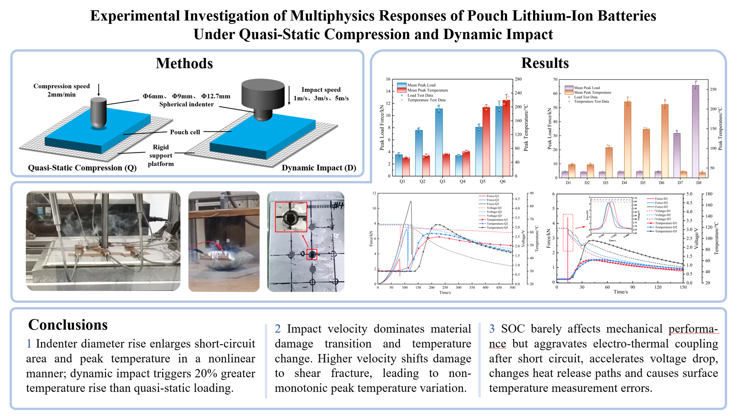
Keywords:
pouch lithium-ion battery
; quasi-static compression
; dynamic impact
; failure mode
; thermal runaway
1. Introduction
In the context of the global energy transition, China’s “dual carbon” goals, and the promulgation of the new EU Battery Regulation [1], new energy vehicles have become a core force driving decarbonization in the transportation sector and optimizing the energy structure, with their market scale achieving step-change growth [2]. In 2025, new energy vehicle sales in China reached 16.49 million units, accounting for a penetration rate of 47.9% [3].
Lithium-ion batteries have become the dominant solution for the battery systems of new energy vehicles due to their excellent energy density, long cycle life, low self-discharge rate and mature industrial chain system [4]. However, battery safety remains a critical bottleneck restricting industry development. In vehicle crash events, lithium-ion batteries may suffer frontal, side, and rear compression and intrusion, potentially resulting in internal battery short circuits, subsequent thermal runaway, and even catastrophic vehicle fires in extreme cases [5]. Therefore, it is vital to investigate the factors influencing battery failure and the mechanical-electrical-thermal responses under different loading conditions, as it provides data support for optimizing battery pack structural safety.
Extensive studies have been conducted on the failure characteristics and damage thresholds of batteries under quasi-static mechanical abuse conditions. Sahraei et al. [6,7] carried out quasi-static compression tests including three-point bending, in-plane compression and local compression on cylindrical and pouch battery cells, 8and confirmed a strong correlation between the occurrence of internal short circuits and structural failure of the battery. Li et al. [8] compared the force-displacement, voltage and temperature responses of cylindrical, pouch and prismatic batteries at the onset of internal short circuits under mechanical indentation conditions, and voltage drop, force drop and temperature rise have been widely recognized as reliable onset indicators of internal short circuits under mechanical abuse loads. Zhou et al. [9] conducted hemispherical punch indentation experiments on pouch batteries and found that the SOC had a negligible effect on the mechanical properties of pouch batteries. Thomas et al. [10] performed a systematic experimental investigation on pouch batteries, revealing that the displacement at short circuit onset declined with rising strain rates, while a non-monotonic correlation existed between strain rates and peak force.
Regarding the characteristics of batteries under dynamic impacts, Huang et al. [11] conducted low-velocity impact tests on 18650 cylindrical batteries and showed that impact energy and state of charge are the key factors governing the mechanical response and internal short-circuit behavior of the cells. Wang et al. [12] conducted multiple drop impact tests on prismatic batteries, and the results indicated that impact mass and impact velocity are the key factors influencing the dynamic failure of lithium-ion batteries. Li [13] comprehensively analyzed the effects of loading direction, loading rate, SOC and indenter type on the battery’s mechanical response curves, open-circuit voltage and surface temperature variations, and clarified the intrinsic correlation mechanism between mechanical loads and internal short circuits in prismatic batteries. Liu et al. [14] conducted mechanical indentation tests and demonstrated the effects of SOC, ISC resistance and electrode area on the electrochemical safety behavior of batteries. Zhou et al. [15] performed dynamic experiments to investigate the mechano-electro coupled failure mechanisms of pouch lithium-ion batteries, clarifying that the dominant failure mechanism under dynamic loading stems from the inertial effect of their multilayer structure rather than the strain rate effect of individual battery components. Kisters et al. [16] conducted local dynamic indentation tests on pouch batteries at various loading rates, and demonstrated the significant effect of strain rate on the mechanical response of the batteries. Deng et al. [17] conducted impact tests on high-capacity pouch batteries under various loading conditions, and demonstrated that the failure behavior of such batteries is jointly governed by the battery’s intrinsic dimensions, indenter geometry and SOC. Liu et al. [18] investigated the effects of dynamic loading on the mechano-electro-thermal coupled responses of new and aged pouch batteries, and the results indicated that batteries are more susceptible to early internal short circuits under dynamic loading conditions, with a markedly accelerated voltage decay rate.
In summary, in terms of quasi-static compression tests, existing studies have mostly focused on investigating the effects of compression modes, compression positions, indenter sizes and other factors on battery failure characteristics, and the compression deformation rate or voltage response is commonly used to determine the battery failure threshold. For dynamic impact tests, certain accumulations have been formed in the experimental studies and systematic analyses on pouch batteries with different SOCs under various impact velocities and indenter sizes. However, a systematic comparative analysis of the differential multiphysics responses and failure mechanisms between quasi-static compression and dynamic impact remains lacking at present.
This study addresses this critical research gap by conducting comprehensive quasi-static compression and drop-weight impact tests on a specific ternary pouch-type lithium-ion battery type. The effects of indenter diameter, impact velocity, and SOC on coupled force-voltage-temperature responses are systematically investigated, and the distinct failure mechanisms under the two loading modes are elucidated. The findings provides essential experimental data and theoretical foundations for the power battery crash safety design and thermal runaway early warning systems.
2. Materials and Methods
2.1. Test Specimens
The pouch cells employed in this experimental study were ternary lithium-ion batteries of a specific specification, as illustrated in Figure 1. These cells measured 202 mm × 151.5 mm × 7.35 mm in dimension, with a rated capacity of 26 A·h and a nominal voltage of 3.65 V. The charge and discharge cut-off voltages were 4.2 V and 2.7 V, respectively. The cathode comprised lithium nickel cobalt manganese oxide (NCM111) active material coated on aluminum foil current collectors, while the anode consisted of graphite active material deposited on copper foil substrates. The separator was composed of polypropylene (PP), and the cell exterior was encapsulated with aluminum-laminated polymer film.
2.2. Quasi-Static Compression Tests
The experiments were conducted in accordance with the test requirements for cell-level mechanical abuse specified in the national standard GB 38031-2025, Safety Requirements for Traction Battery of Electric Vehicles [19], as well as testing conditions documented in relevant literature [7,20]. Spherical indenters were employed. The compression tests were performed using an AG-X plus universal testing machine, which enabled synchronous acquisition of load-displacement data. Voltage signals were recorded using a oscilloscope, while temperature data were collected via contact thermocouples and an XSR40 data logger. To ensure operational safety, a custom-designed explosion-proof chamber with top ventilation was constructed. The quasi-static compression test setup is shown in Figure 2a.
The quasi-static compression was applied at a constant velocity of 2 mm/min. To eliminate potential initial clearance, data recording was initiated when the applied load exceeded 20 N. Loading was terminated when the force decreased to 50% of the peak value, which was defined as the crushing failure of the cell. A 10-minute post-crushing observation period was maintained to monitor subsequent voltage evolution. To capture the voltage and temperature responses during spherical indentation, the pouch cell terminals were connected to the oscilloscope, and thermocouples were strategically positioned on the cell surface, as illustrated in Figure 2b, facilitating subsequent analysis of the surface temperature distribution.
The quasi-static compression test conditions are summarized in Table 1. These conditions were designed to investigate the ultiphysics response characteristics of force-voltage-temperature coupling following battery failure, with particular emphasis on the effects of indenter geometry and SOC. To ensure result reliability, each test condition was replicated three times to mitigate potential variations arising from battery production batches.
2.3. Impact Tests
Dynamic drop-weight impact tests were conducted using a JY-6010D gravity impact testing machine. The host computer interface enabled configuration of sample parameters and drop height settings, while facilitating real-time acquisition of voltage and temperature data. Voltage and cell surface temperature were measured using identical methodologies to those employed in the quasi-static tests. A drop-weight assembly with a total mass of 15 kg was combined with indenters of various radii. The detailed experimental configuration is presented in Figure 3. High-speed imaging coupled with single-point digital image correlation (DIC) was employed to quantify the indenter penetration depth, as shown in Figure 4. The impact speed, indenter diameter, and SOC for each dynamic impact test group are presented in Table 2.
3. Results
3.1. Quasi-Static Compression Tests
During quasi-static compression, luminous ignition was observed at the compressed region, accompanied by pronounced smoke emission. The stress concentration induced by the spherical indenter caused the compressive stress in localized regions, encompassing the aluminum-laminated film, current collectors, and separator to exceed critical thresholds, resulting in total structural failure. Upon separator rupture, ISC triggered by direct contact between the positive and negative electrodes generated Joule heating, which rapidly vaporized and decomposed the electrolyte, producing the observed smoke, as illustrated in Figure 5a.
The damaged region exhibited multi-material synergistic failure. The central area displayed black-brown discoloration with significant peripheral temperature elevation. At the spherical indenter contact point, fracture of the aluminum layer and tearing of the polymer sealant in the laminated film were evident, exposing the plastically deformed current collectors of both electrodes, as shown in Figure 5b.
3.1.1. Repeatability Verification
To ensure experimental reliability, triplicate tests were conducted for each test condition to mitigate variations attributable to manufacturing tolerances in internal resistance, capacity, and other cell parameters. Taking Condition Q3 as an exemplar, pouch cells at 0% SOC were prepared with terminal voltages controlled within 3.15 ± 0.03 V (corresponding to a tolerance of ±1%). The repeatability results are presented in Figure 6.
This test group exhibited excellent repeatability in both the force-displacement curves and the voltage and temperature profiles. As shown in Figure 6a, the three peak force values were 11.58 kN, 10.95 kN, and 10.97 kN, yielding an average relative error of 2.06%. The cell failure depth thresholds at failure were 4.43 mm, 4.34 mm, and 4.26 mm, with an average relative error of 1.33%. The peak temperatures for the three tests were 63.1℃, 65.7 ℃, and 64.5℃, corresponding to an average relative error of 1.38%.
As illustrated in Figure 6b, the voltage evolution in all three tests followed a characteristic pattern of “stability–sharp drop–rebound–decay.” The voltage drop coincided precisely with the load drop, indicating that structural failure and the onset of internal short circuit occurred simultaneously. During the decay phase, minor variations in voltage decline rates across different tests were observed, which were primarily attributed to the synergistic effects of non-uniform electrolyte distribution and variations in ionic conduction efficiency within the cells.
The error analysis results for all quasi-static test groups are presented in Figure 7. These results confirm that the cells exhibited highly consistent mechanical, electrical, and thermal responses, validating the reliability of the experimental data for subsequent analysis.
3.1.2. Influence of Indenter Diameter
To investigate the influence of indenter diameter on the compression response of pouch cells, comparative analyses were conducted using the results from test conditions Q1-Q3 and Q4-Q6. The results are presented in Figure 8.
The results reveal significant correlations between indenter diameter and the mechanical, electrical, and thermal responses. The peak compression force increased substantially with indenter diameter: for conditions Q1–Q3, the values were 3.29 kN, 7.27 kN, and 10.97 kN; for conditions Q4–Q6, the corresponding values were 3.41 kN, 7.72 kN, and 11.52 kN. This enhancement arises because larger-diameter indenters engage greater contact areas, necessitating the overcoming of synergistic load-bearing resistance from multiple components including the packaging layer, electrode stack, and separator, thereby resulting in elevated mechanical load peaks.
Both the magnitude of voltage drop and the rate of voltage decay increased with indenter diameter. This behavior is attributed to the more severe damage inflicted on constituent materials within the compression zone as indenter diameter increases, which produces correspondingly larger short-circuit contact areas between the positive and negative electrodes, manifesting as more abrupt voltage drops and accelerated decay characteristics.
The temperature rise rate and peak temperature also increased with indenter diameter. For group Q1-Q3, the peak temperatures were 56.4 °C, 59.1 °C, and 65.7 °C sequentially. This elevation is attributed to the larger internal short-circuit area associated with larger-diameter indenters, generating increased heating. Notably, no thermal runaway was observed under any of these three conditions. In contrast, group Q4-Q6 exhibited peak temperatures of 70.4 °C, 192.2 °C, and 219.6 °C, with thermal runaway triggered in conditions Q5 and Q6.
In summary, the indenter diameter modulates the contact stress distribution and damage area, thereby quantitatively regulating the mechanical abuse response of pouch cells and determining the nonlinear coupled mechano-electrochemical-thermal behavior.
3.1.3. Influence of SOC
To investigate the influence of elevated SOC on the compression failure behavior of pouch cells, comparative analyses were conducted using results from conditions Q1-Q6, as summarized in Table 3.
The data in Table 3 demonstrate that both the temperature rise rate and maximum temperature increased significantly with SOC. No thermal runaway was observed in test groups Q1-Q4. In Q4, the indenter with 6 mm diameter produced localized penetration without establishing an effective internal short-circuit pathway; consequently, no immediate voltage drop was detected, though the voltage decayed to 0 V after 24 hours of observation.
Under conditions Q5 and Q6, the cell voltage decayed rapidly approximately 50 seconds following battery structure failure, accompanied by sharp temperature elevation and subsequent thermal runaway. The peak temperatures reached 192.2 °C and 219.6 °C, respectively. The primary mechanism driving thermal runaway involves the combination of large short-circuit area and the synergistic amplification of Joule heating and parasitic reaction heat at elevated SOC states. This coupling substantially enhances electrochemical reaction kinetics within the cell, causing heat accumulation rates to substantially exceed heat dissipation capacity, ultimately triggering thermal runaway.
Conversely, SOC exhibited limited influence on the peak load and failure displacement under quasi-static compression. Comparative analysis across indenter conditions revealed that 20% SOC produced only marginal increases in peak force (3.4%-4.9%) and failure displacement (1.1%-3.6%). This modest enhancement primarily stems from the volume expansion of litigated graphite in the negative electrode during charging, which induces slight overall cell swelling and generates internal pre-stress. During initial compression stages, this pre-stress partially counteracts the external mechanical load, thereby marginally improving the structural load-bearing capacity, a finding consistent with the results reported in Reference [21].
The internal failure morphology further corroborates these observations, as illustrated in Figure 9 and Figure 10. Batteries at 20% SOC exhibited luminous ignition, rapid electrolyte volatilization, and fire initiation within the compressed region upon failure. Post-test examination revealed outer aluminum-laminated film melting and shrinkage with localized carbonization and ablation. Disassembly demonstrated severe structural damage to the cell main body, with the central region exhibiting perforation and carbonized charring characteristics.
In summary, elevated SOC exerts relatively limited influence on the macroscopic mechanical properties of cells, yet substantially intensifies the post-short-circuit electrochemical–thermal coupling effects. These effects manifest as accelerated voltage decay rates and more pronounced temperature elevation, with the amplification becoming increasingly prominent at larger indenter diameters, thereby significantly elevating the probability of thermal runaway initiation.
3.2. Drop-Weight Impact Tests
3.2.1. Repeatability Verification
The error analysis was conducted using methodologies identical to those employed for the quasi-static test groups, with results presented in Figure 11. The analysis confirms that the cells exhibited satisfactory consistency in mechanical response, electrical behavior, and thermal characteristics under dynamic loading conditions.
3.2.2. Influence of Indenter Diameter
To investigate the influence of indenter diameter on the failure behavior of pouch cells under dynamic impact conditions, comparative analyses were performed using results from test groups D1–D3. The mechanical-electrical-thermal response data are presented in Figure 12, and the corresponding surface damage morphologies are illustrated in Figure 13. The results reveal that the evolution trends of load, voltage, and temperature under dynamic impact differ substantially from those observed under quasi-static compression.
As shown in Figure 12 and Figure 13, the substantial impact energy under dynamic loading resulted in complete penetration of the cell by the 6 mm diameter indenter in group D1, where significant stress concentration effects accelerated localized rupture of the separator and electrode structures. The peak force reached 4.41 kN, marginally exceeding those of the other two groups. In groups D2 and D3, the 9 mm and 12.7 mm diameter spherical indenters did not achieve full penetration; internal material damage was dominated by bulk plastic deformation and interlayer slip, with peak forces of 4.13 kN and 4.22 kN, respectively, showing substantial consistency. Unlike the significant force-diameter correlation observed in groups Q1-Q3, the loading forces in groups D1-D3 remained essentially comparable.
Figure 13 reveals that the smaller indenters in groups D1 and D2 induced localized penetration-type internal short circuits, triggering early hard short circuits characterized by severe and irreversible voltage drops. However, the complete penetration damage created heat dissipation pathways, and the limited instantaneous heat accumulation from the short circuit resulted in relatively low peak temperatures. Conversely, Larger indenters induced elastic-plastic deformation in the aluminum-laminated film and positive/negative electrodes. Upon indenter rebound, elastic recovery of the electrode sheets and separator caused separation of contact interfaces, resulting in soft short circuit behavior. Although the voltage decay rate was more gradual compared to small indenters, the substantially larger short-circuit contact area generated increased Joule heating, ultimately producing elevated temperature rise rates and peak temperatures.
In summary, unlike the strong correlation between force-electrical-thermal characteristics and indenter diameter observed in quasi-static conditions, dynamic impact scenarios exhibit significant associations between indenter diameter and damage morphology as well as voltage drop reversibility, influenced by variations in stress concentration and damage mode. The experimental measurements indicate that among the parameters investigated, only temperature rise and peak temperature demonstrate significant positive correlation with indenter diameter, whereas peak force and voltage decay profiles remain essentially consistent.
3.2.3. Effect of Impact Velocity on Cell Failure Characteristics
To investigate the influence of impact velocity on the failure behavior of pouch cells, test groups D3, D7, and D8 were selected for comparative analysis. The experimental results are presented in Figure 14, and the corresponding cell damage morphologies are illustrated in Figure 15.
As shown in Figure 14, the peak load increased substantially with impact velocity. This enhancement occurs because once the threshold force for cell penetration is exceeded, the primary reaction force originates from contact between the indenter and the rigid base plate. Figure 15 visually demonstrates the evolution of cell damage morphology with increasing impact velocity: at low velocities, localized indentation features dominate, whereas high-velocity impact produces localized through-thickness damage characterized by smooth, planar fracture surfaces exhibiting typical shear failure characteristics. This transition indicates that the internal material damage mode has shifted from plastic deformation at low velocities to brittle shear fracture at high velocities.
Brittle shear fracture causes rapid rupture and separation of the separator, and electrodes within an extremely short timeframe, precluding the formation of sustained stable short-circuit pathways [11,22]. This process simultaneously restricts current conduction and Joule heat generation while suppressing exothermic parasitic reactions at the electrode-electrolyte interface, ultimately resulting in voltage decay rates and peak temperatures that do not exhibit systematic variation with impact velocity. These findings demonstrate that impact velocity fundamentally alters the internal material damage mode, thereby transforming the transient characteristics of short-circuit behavior and the heat accumulation process. This has significant implications for assessing battery safety performance under high-dynamic-loading conditions.
3.2.4. Effect of State of Charge on Cell Failure Characteristics
To investigate the influence of varying SOC on cell failure characteristics, comparative analyses were conducted using temperature and voltage data from test groups D3-D6, with results presented in Figure 16. Consistent with findings reported in References [15,17,23] regarding dynamic impact conditions, the macroscopic mechanical response exhibited negligible dependence on SOC, whereas SOC exerted a dominant influence on voltage decay behavior and thermal response characteristics. Consequently, the present analysis focuses primarily on voltage and temperature responses.
As shown in Figure 16a, SOC exerts a decisive influence on the voltage decay rate. In groups D3 and D4, cells at 0% and 20% SOC exhibited distinctly gradual voltage drops. In group D5, the cell at 50% SOC demonstrated relatively rapid voltage decay, though complete failure was marginally delayed. In group D6, the cell at 100% SOC experienced precipitous voltage collapse to 0 V within 10 seconds post-impact, exhibiting instantaneous internal short circuit behavior. These observations indicate that elevated SOC enhances internal electrochemical activity, thereby accelerating the impact-induced ISC progression.
Concurrently, the severity of the damaged cell response increased substantially with SOC. Upon indenter impact, localized stress concentration rapidly perforated the separator, and direct contact between positive and negative electrodes triggered instantaneous internal short circuits accompanied by spark generation. The rapid conversion of electrochemical energy into Joule heating provided initial thermal energy for runaway initiation. As the ISC propagated, substantial electrolyte volatilization and gas generation produced significant internal pressure elevation, resulting in pronounced cell bulging and deformation. In tests D3 and D4, where SOC was relatively low, internal pressure was primarily released through rupture of the aluminum-laminated film at the impacted site, confining the thermal runaway zone. Conversely, in tests D5 and D6, elevated SOC produced high-temperature gas and electrolyte jetting from lateral pressure relief vents accompanied by open flame, as illustrated in Figure 17.
The failure morphologies further corroborate this analysis, as presented in Figure 18. The indenter contact region exhibited severe crushing, while the overall cell displayed extensive bulging and laminate structural collapse. Lateral rupture of the aluminum-laminated film with large-area carbonization and ablation reflected lateral electrolyte jetting and combustion during thermal runaway. Exposed electrodes and active materials were visible in the impact zone, indicating that under high-SOC conditions, mechanically induced ISCs can rapidly evolve into thermally dominated structural failure modes.
However, in the present experiments, thermocouples were positioned on the upper cell surface near the impact center. The lateral venting jetting and combustion processes substantially altered the heat release pathway, significantly reducing heat accumulation in the upper surface region; consequently, the recorded temperature peaks were relatively low. In contrast, cells at 20% SOC exhibited only bulging without lateral rupture, concentrating heat release primarily in the upper impact region and thereby producing higher measured temperature peaks. This phenomenon resulted in the non-monotonic relationship between temperature peak and SOC observed in Figure 16b. Therefore, comprehensive assessment of thermal safety under mechanical abuse requires integrated consideration of both internal heat generation intensity and external pressure relief pathways; surface temperature measurements cannot fully capture the true severity of thermal runaway.
4. Discussion
To elucidate the differential effects of quasi-static compression and dynamic impact on the failure characteristics of pouch cells, comparative analyses were conducted using results from test conditions Q3, Q4, D3, and D4. The comparative results are presented in Figure 19.
Synthesizing the aforementioned experimental results, the loading rate governs distinct failure mode transitions, resulting in markedly different voltage decay and temperature evolution characteristics under quasi-static compression versus dynamic impact. The principal distinctions are as follows:
(1) Mechanical Response Differences: Continuity versus Transience in Load Bearing
Under quasi-static compression, the multilayer structure of the cell participates sequentially in load bearing, producing force-displacement curves with characteristic elastoplastic behavior and pronounced continuity. The peak load reached 11 kN. Large-diameter indenters must overcome the synergistic load-bearing resistance of the aluminum-laminated film, electrode stack, and separator, with failure manifested as progressive plastic deformation and interlayer slip.
Under dynamic impact, the load is applied extremely rapidly, causing internal materials to undergo localized shear fracture more readily under high-strain-rate conditions. The peak load is substantially reduced to only 4.22 kN. This disparity arises from the strain-rate sensitivity of the separator and active coating materials, which exhibit ductility under slow loading but brittleness under high-velocity impact.
(2) Electrical Response Differences: Distinct Short-Circuit Conduction Characteristics
Under quasi-static compression, internal short circuits typically form progressively with structural degradation, establishing stable and sustained short-circuit pathways upon separator rupture. As observed in groups Q3 and Q4, the voltage exhibits continuous decay.
Under dynamic impact, intermittent micro-short-circuits produced voltage responses characterized by multiple rebounds followed by gradual decay, as exemplified by group D3. This indicates that the damage morphology under high-velocity impact cannot sustain stable low-resistance conduction pathways, rendering voltage decay more difficult to predict.
(3) Thermal Response Differences: Failure Mode and Heat Accumulation Capacity
Under quasi-static compression, the sustained nature of short-circuit conduction allows Joule heating and parasitic reaction heat to accumulate gradually in localized regions without significant venting. This results in slow temperature elevation: in group Q4, although the peak temperature reached 219.6 °C due to superimposed parasitic reaction heat from thermal runaway, the peak occurred at 146 seconds with a gentle heating rate, concentrating heat release in the compression zone.
Conversely, under dynamic impact, rapid structural destruction provides more direct pathways for heat release: in group D4, the heating rate was precipitous upon thermal runaway initiation, with the peak temperature reaching 302 °C within 15 seconds of voltage collapse. The comparison between Q3 and D3 further corroborates this conclusion. The maximum temperature difference was merely 18.2 °C, yet the time to peak was delayed by 84 seconds, demonstrating substantial hysteresis in energy accumulation.
These comparative results demonstrate that assessment of battery safety under mechanical abuse must explicitly distinguish loading conditions and establish strain-rate-dependent multiphysics coupled failure criteria.
5. Conclusions
This study systematically investigated the coupled mechano-electro-thermal response characteristics of pouch lithium-ion batteries under varying indenter diameters, impact velocities, and SOCs through quasi-static compression and dynamic drop-weight impact testing. The findings demonstrate that indenter geometry and impact velocity govern the contact stress distribution and damage zone scale, significantly influencing voltage decay rates and temperature elevation levels in a positively correlated manner. The principal conclusions are as follows:
(1) Essential distinctions in multiphysics responses between quasi-static compression and dynamic impact: Mechanically, quasi-static compression exhibits continuous load-bearing characteristics with progressive plastic deformation failure modes, whereas dynamic impact demonstrates transient load bearing that induces brittle shear fracture in internal materials. Electrically, quasi-static compression establishes stable and sustained short-circuit pathways with continuous voltage decay, while dynamic impact produces soft short-circuit conditions (when penetration is incomplete) causing multiple voltage rebounds. Thermally, quasi-static compression enables gradual heat accumulation, while dynamic impact produces precipitous temperature rise with substantial temporal disparity in energy accumulation.
(2) Linear increase in indenter diameter promotes corresponding expansion of short-circuit area, thereby elevating peak temperature; however, the relationship exhibits nonlinear characteristics. Under non-thermal-runaway conditions with consistent indenter increments, the temperature elevation amplitude in dynamic impact scenarios exceeded that in quasi-static conditions by approximately 20%.
(3) Dynamic impact velocity represents the dominant factor governing internal material damage mode transitions and temperature evolution. With increasing impact velocity, the damage mode transitions from plastic deformation under slow loading to high-strain-rate shear fracture, where transient contact characteristics restrict sustained short-circuit current and electrochemical parasitic reactions, resulting in non-monotonic temperature peak variation with impact velocity.
(4) Elevated SOC exerts relatively limited influence on macroscopic mechanical properties but substantially intensifies post-short-circuit electrochemical-thermal coupling effects, accelerating voltage decay rates and increasing temperature elevation amplitudes. High SOC conditions transform thermal runaway heat release pathways from localized venting at the compression site to comprehensive lateral venting, introducing measurement inaccuracies in surface temperature monitoring.
Limitations: The present study is constrained by sample availability, precluding surface temperature measurement and data correction under high-SOC conditions. Additionally, experimental limitations prevented implementation of high-SOC thermal runaway tests under quasi-static conditions, resulting in an asymmetric experimental matrix.
Synthesis: The failure behavior of pouch lithium-ion batteries under compression and impact conditions exhibits pronounced multiphysics coupling characteristics, with voltage and temperature responses jointly influenced by indenter geometry, loading rate, and SOC. The systematic experimental results obtained herein provide critical empirical foundations and theoretical support for impact-resistant structural protection design of power battery packs, vehicle collision safety assessment, and formulation of thermal runaway early-warning strategies. Future research will extend the established methodological framework to additional battery chemistries and alternative packaging configurations, integrating microstructural characterization techniques and finite element analysis to elucidate internal material damage evolution mechanisms and multiphysics coupling response patterns under impact loading.
Author Contributions
Conceptualization, L.Y.; methodology, L.Y.; validation, L.Y., S.X., Y.Z. and J.F.; formal analysis, L.Y.; investigation, L.Y., S.X., Y.Z. and J.F.; resources, J.L.; data curation, L.Y. and S.X.; writing—original draft preparation, L.Y.; writing—review and editing, L.Y., S.X. and J.X.; visualization, L.Y. and S.X.; supervision, L.Y.; project administration, L.Y.; funding acquisition, L.Y. All authors have read and agreed to the published version of the manuscript.
Funding
This research was funded by Natural Science Foundation of Fujian Province, grant number 2022J01612.
Data Availability Statement
The original contributions presented in the study are included in the article, further inquiries can be directed to the corresponding author.
Acknowledgments
The tests were conducted at Key Laboratory of Safety Detection and Evaluation Technology of New Energy Batteries with High Specific Energy, in Xiamen Products Quality Supervision & Inspection Institute. The authors gratefully acknowledge the technical support provided by the institute’s team.
Conflicts of Interest
The authors declare no conflicts of interest.
References
- Central Committee of the Communist Party of China State Council Opinions on Fully; Accurately and Comprehensively Implementing the New Development Concept to Achieve Carbon Peaking and Carbon Neutrality. Available online: https://www.gov.cn/zhengce/2021-10/24/content_5644613.htm (accessed on 17 April 2026).
- Duan, X.Y.; Zhu, K.K. Quantitative Analysis of Policy Texts on New Energy Vehicle Batteries in China. Resour. Dev. Mark. 2025, 1–20. [Google Scholar]
- Wang, Y.L.; Guo, L.; Yang, Z.Y.; et al. Research on the Optimization of Integrated Energy Systems Considering the Interaction between Electric Vehicle Swap Stations and Multi-Energy Regulation. Power Syst. Technol. 2025, 1–15. [Google Scholar]
- Cai, Y.S.; Jing, W.T. Innovation-Driven Developments in Automotive Lithium-Ion Battery Technologies: A Patent-Based Comparison of China and the United States. Energy Storage Sci. Technol. 2025, 14(10), 4043–4053. [Google Scholar]
- Li, T.; Ying, L.; Xu, J.Q.; et al. Establishment and Multiple Conditions Validation of Homogenization Model of Lithium-Ion Pouch Cells. Mech. Electr. Technol. 2025, (01), 21–26. [Google Scholar]
- Sahraei, E.; Kahn, M.; Meier, J.; et al. Modelling of Cracks Developed in Lithium-Ion Cells under Mechanical Loading. RSC Adv. 2015, 5(98), 80369–80380. [Google Scholar] [CrossRef]
- Sahraei, E.; Meier, J.; Weerzbicki, T. Characterizing and Modeling Mechanical Properties and Onset of Short Circuit for Three Types of Lithium-Ion Pouch Cells. J. Power Sources 2014, 247, 503–516. [Google Scholar] [CrossRef]
- Wei, L.I.; Yong, X.; Guan, H.C.; et al. Comparative Study of Mechanical-Electrical-Thermal Responses of Pouch, Cylindrical, and Prismatic Lithium-Ion Cells under Mechanical Abuse. Sci. China Technol. Sci. 2018, 61(3), 383–394. [Google Scholar]
- Luo, H.; Xia, Y.; Zhou, Q. Mechanical Damage in a Lithium-Ion Pouch Cell under Indentation Loads. J. Power Sources 2017, 357, 61–70. [Google Scholar] [CrossRef]
- Tancogne-Dejean, T.; Grollau, V.; Mohr, D. Strain Rate Dependent Plasticity of Lithium-Ion Pouch Cells: Experiments and Simulations. Int. J. Impact Eng. 2022, 159, 104048. [Google Scholar] [CrossRef]
- Huang, Q.; Bai, Y.; Luo, H.; et al. Dynamic Multi-Physics Behaviors and Performance Loss of Cylindrical Batteries upon Low-Velocity Impact Loading. Energy Environ. Mater. 2024, 7(6), 184–192. [Google Scholar] [CrossRef]
- Li, Z.J. Load Deformation Failure Test and Simulation Analysis for Internal Configuration of Prismatic Lithium-Ion Batteries on New Energy Vehicle. Ph.D. Thesis, South China University of Technology, Guangzhou, China, 2021. [Google Scholar]
- Wang, T.; Meng, K.P.; Liu, Y.Z.; et al. Effects of Impact Mass on Dynamic Mechanical Responses and Failure Modes of Square Lithium-Ion Batteries under Impact Loading. Explos. Shock Waves 2025, 45(2), 49–64. [Google Scholar]
- Liu, B.; Jia, Y.; Li, J.; et al. Safety Issues Caused by Internal Short Circuits in Lithium-Ion Batteries. J. Mater. Chem. A 2018, 6(43), 21475–21484. [Google Scholar] [CrossRef]
- Zhou, M.Z.; Hu, L.L.; Chen, S.R.; et al. Different Mechanical-Electrochemical Coupled Failure Mechanism and Safety Evaluation of Lithium-Ion Pouch Cells under Dynamic and Quasi-Static Mechanical Abuse. J. Power Sources 2021, 497, 229897. [Google Scholar] [CrossRef]
- Kisters, T.; Gilaki, M.; Nau, S.; et al. Modeling of Dynamic Mechanical Response of Li-Ion Cells with Homogenized Electrolyte-Solid Interactions. J. Energy Storage 2022, 49, 104069. [Google Scholar] [CrossRef]
- Deng, J.; Kumar, A.; Simynovic, S.; et al. Mechanical Modeling and Testing of Pouch Cells under Various Loading Conditions. J. Electrochem. Soc. 2020, 167(13), 130537. [Google Scholar] [CrossRef]
- Liu, Y.; Xia, Y.; Xing, B.; et al. Mechanical-Electrical-Thermal Responses of Lithium-Ion Pouch Cells under Dynamic Loading: A Comparative Study between Fresh Cells and Aged Ones. Int. J. Impact Eng. 2022, 166, 104237. [Google Scholar] [CrossRef]
- Standardization Administration of China. GB/T 38031-2025: Safety Requirements for Traction Batteries for Electric Vehicles [S]. Beijing: China Quality Standards Publishing and Media Co., Ltd., 2025.
- Chung, S.H.; Tancogne-Dejean, T.; Zhu, J.; et al. Failure in Lithium-Ion Batteries under Transverse Indentation Loading. J. Power Sources 2018, 389, 148–159. [Google Scholar] [CrossRef]
- Wang, K.F.; Liu, T.; Zhang, M. Study on Expansion Internal Stress of LFP Battery during Charging or Discharging. J. Yanshan Univ. 2025, 49(2), 130–136. [Google Scholar]
- Luo, H.L. Structural Failure Mechanism and Modelling of Lithium-Ion Battery Pouch Cell under Mechanical Abuse. Ph.D. Thesis, Tsinghua University, Beijing, China, 2018. [Google Scholar]
- Guo, Y.Z.; Liu, X.C.; Bai, C.Y.; et al. Dynamic Response Characteristics of Soft-Pack Lithium Batteries for Light Weight Consumer Drones under Mechanical Strong Impact Loads. Explos. Shock Waves 2025, 45(2), 65–75. [Google Scholar]
Figure 1.
Pouch lithium-ion cell sample.
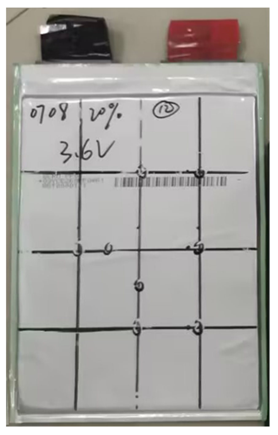
Figure 2.
(a) Quasi-static compression test setup. (b) Temperature measurement point layout on the battery surface.
Figure 2.
(a) Quasi-static compression test setup. (b) Temperature measurement point layout on the battery surface.
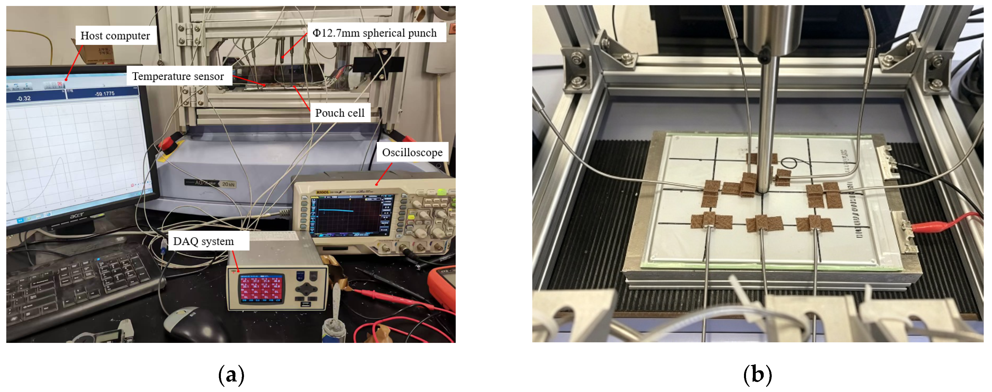
Figure 3.
Dynamic impact test setup.
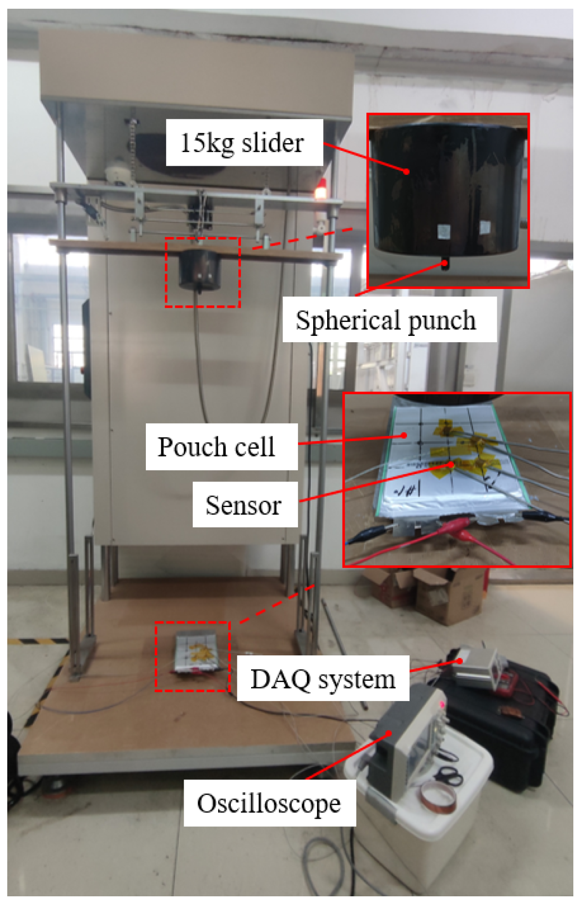
Figure 4.
Combined measurement using high-speed camera and DIC. (a) High-speed camera images. (b) Single-point calibration measurement.
Figure 4.
Combined measurement using high-speed camera and DIC. (a) High-speed camera images. (b) Single-point calibration measurement.
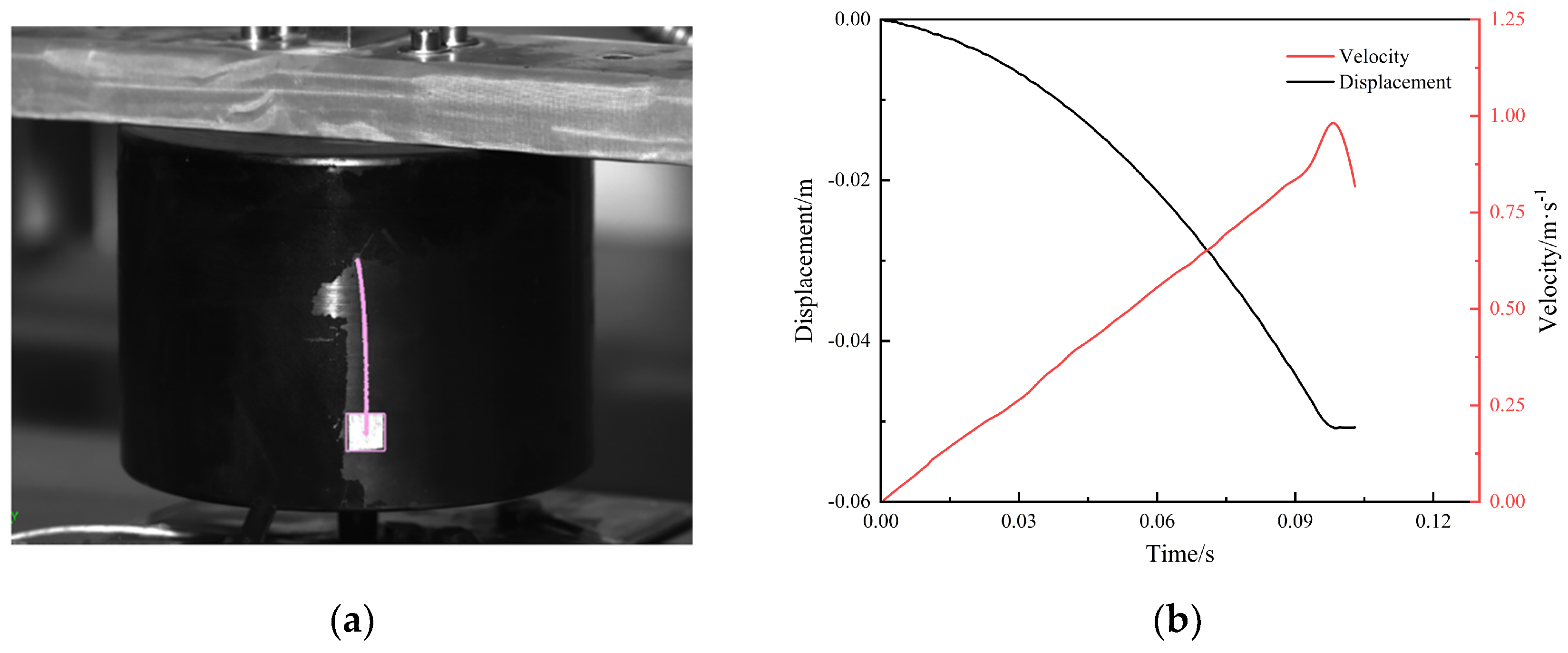
Figure 5.
Test phenomena of group Q3. (a) Under testing. (b) Damage results.
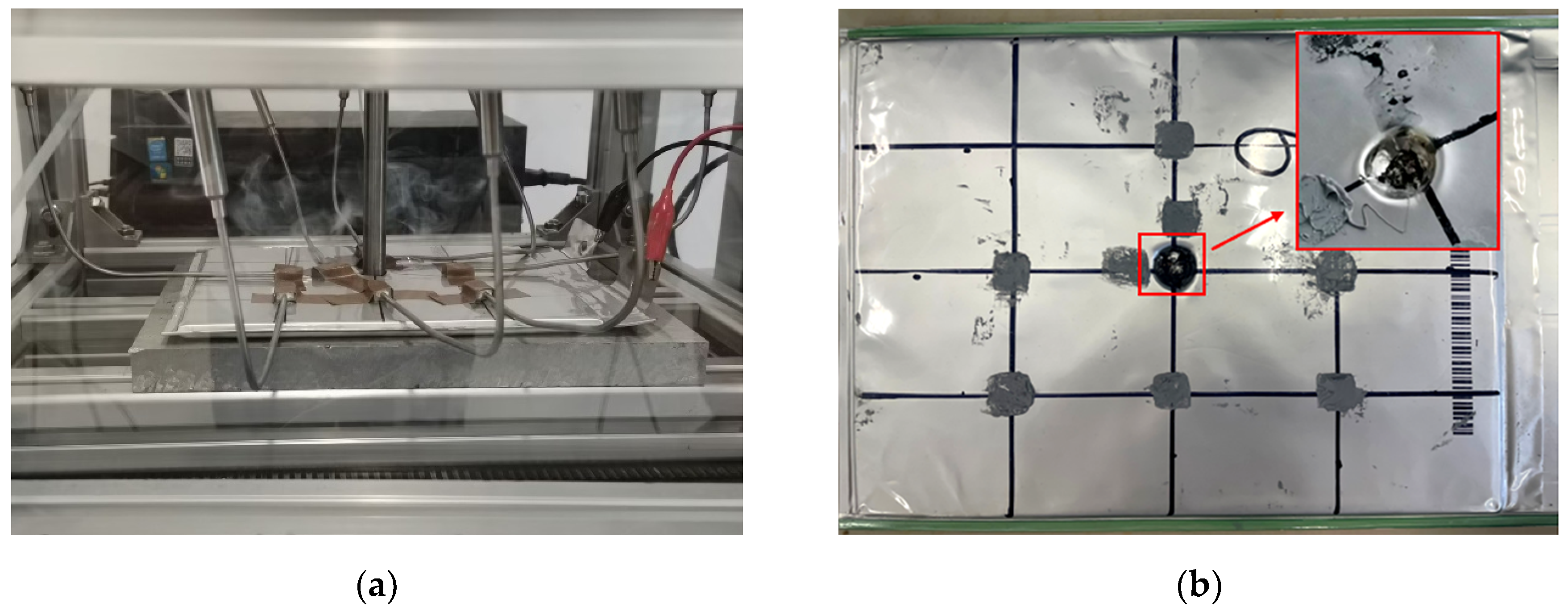
Figure 6.
Repeatability test results of group Q3. (a) Load response. (b) Voltage-temperature.
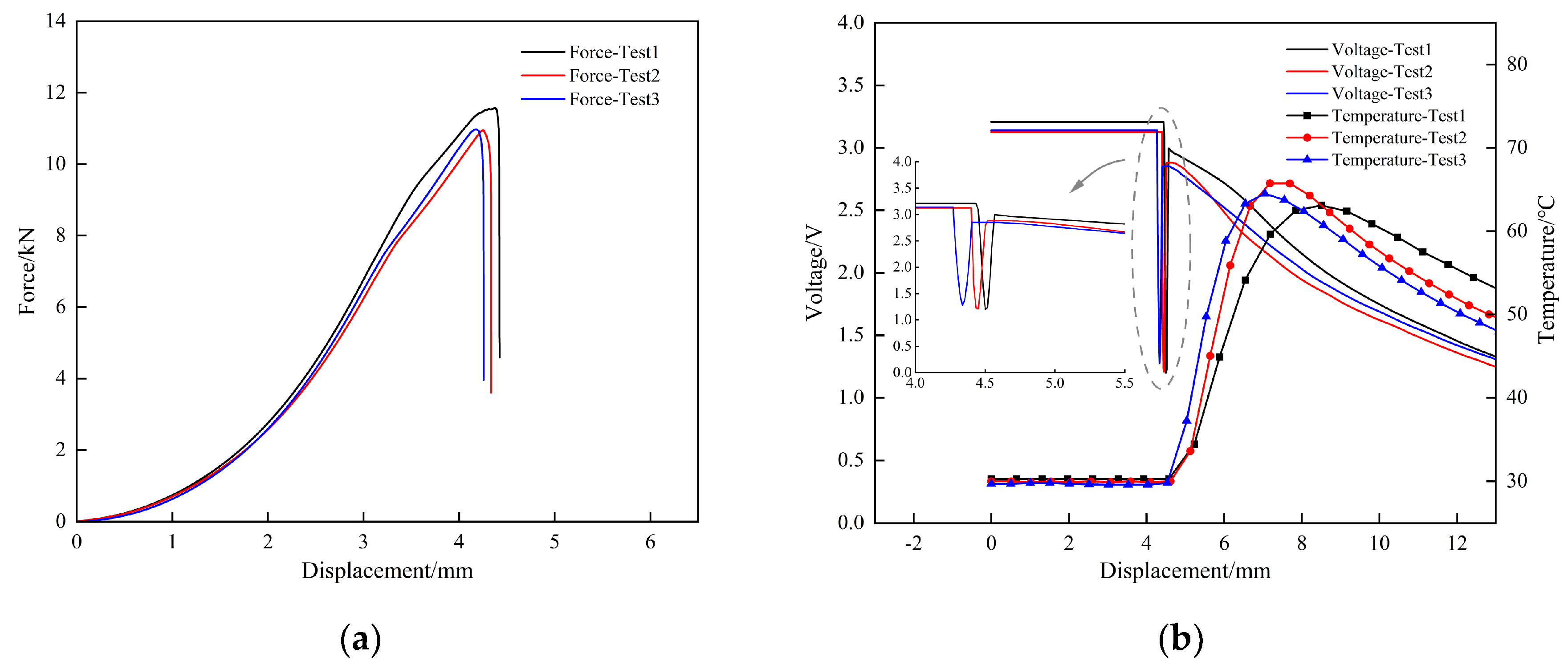
Figure 7.
Comparison of Mean Peak Load and Mean Peak Temperature in Q1–Q6 Test Groups.
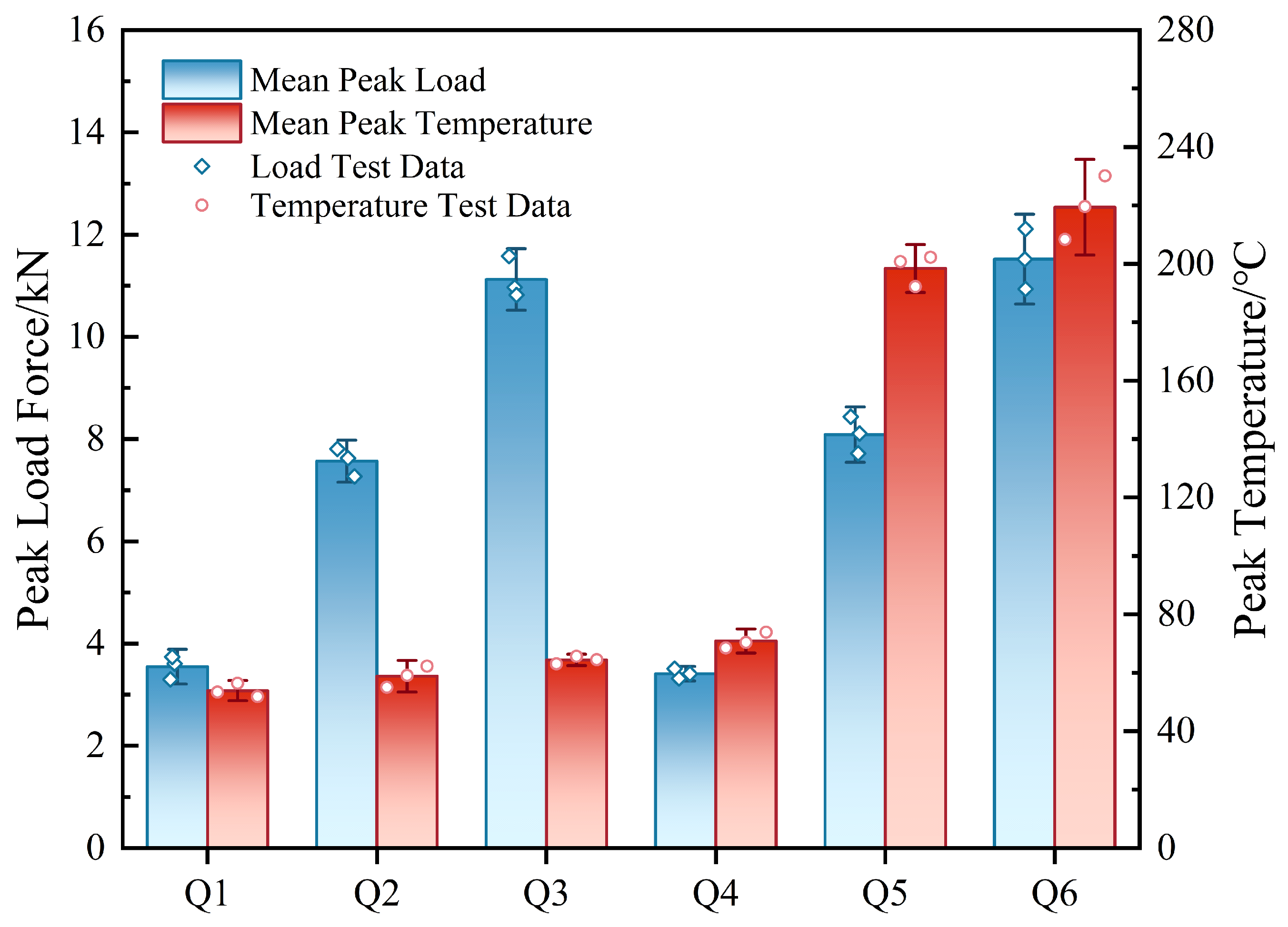
Figure 8.
(a) Force-electrical-thermal response results of test groups Q1 to Q3. (b) Force-electrical-thermal response results of test groups Q4 to Q6.
Figure 8.
(a) Force-electrical-thermal response results of test groups Q1 to Q3. (b) Force-electrical-thermal response results of test groups Q4 to Q6.
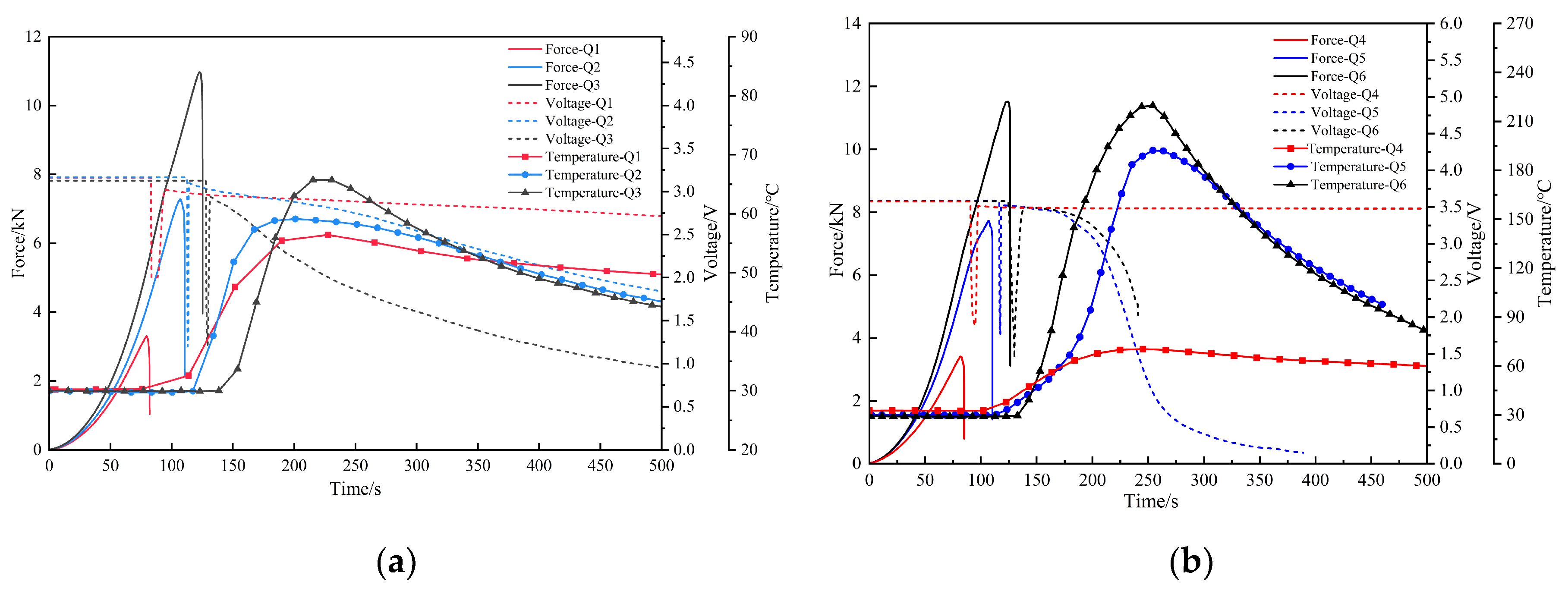
Figure 9.
Damage locations after quasi-static compression with different indenters. (a) 6mm diameter indenter in test Q1. (b) 12.7mm diameter indenter in test Q3.
Figure 9.
Damage locations after quasi-static compression with different indenters. (a) 6mm diameter indenter in test Q1. (b) 12.7mm diameter indenter in test Q3.
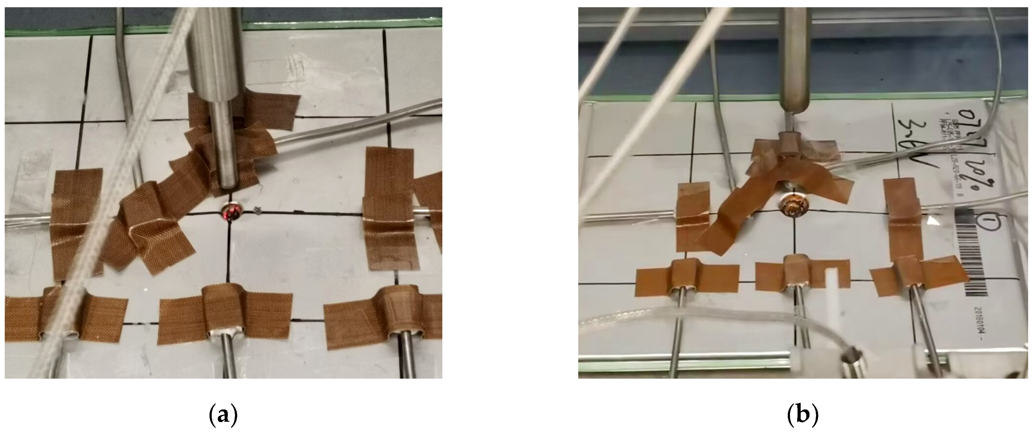
Figure 10.
Surface and internal damage morphologies of the cells after compression with different indenters. (a) Surface morphology of test Q5. (b) Surface morphology of test Q6. (c) Internal morphology of test Q6.
Figure 10.
Surface and internal damage morphologies of the cells after compression with different indenters. (a) Surface morphology of test Q5. (b) Surface morphology of test Q6. (c) Internal morphology of test Q6.
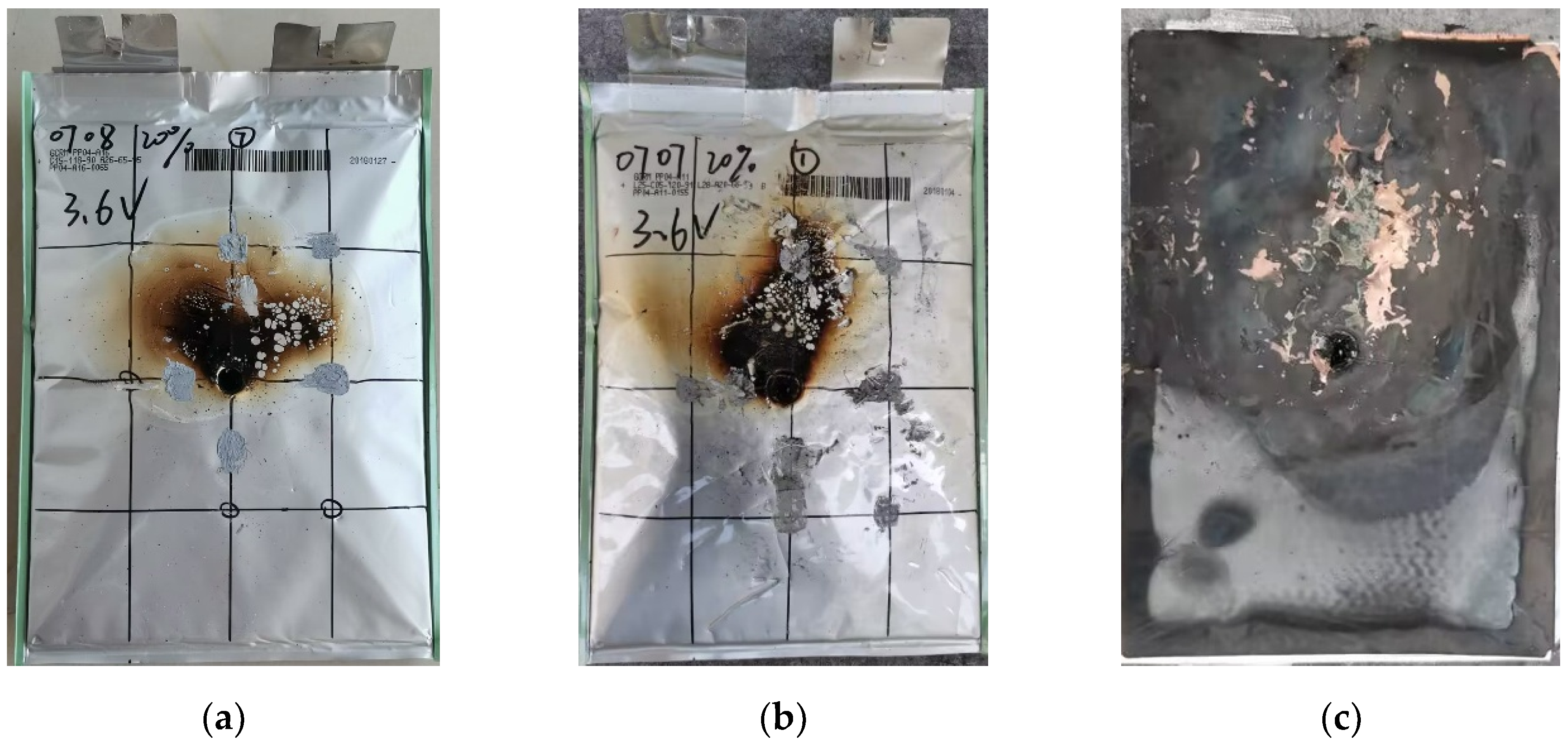
Figure 11.
Comparison of Mean Peak Load and Mean Peak Temperature in D1-D8 Test Groups.
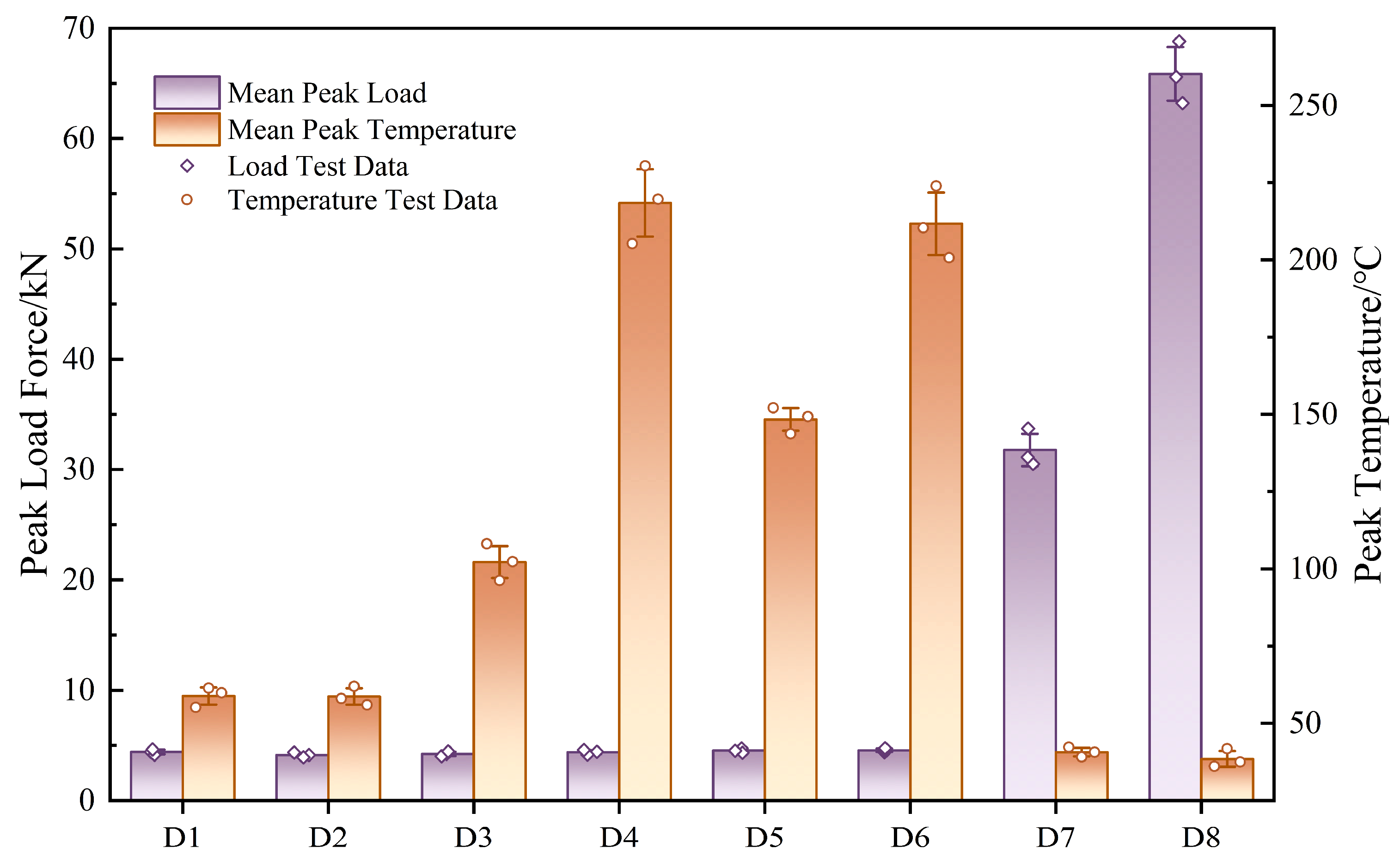
Figure 12.
Test results of groups D1~D3 under dynamic impact with different indenter diameters.
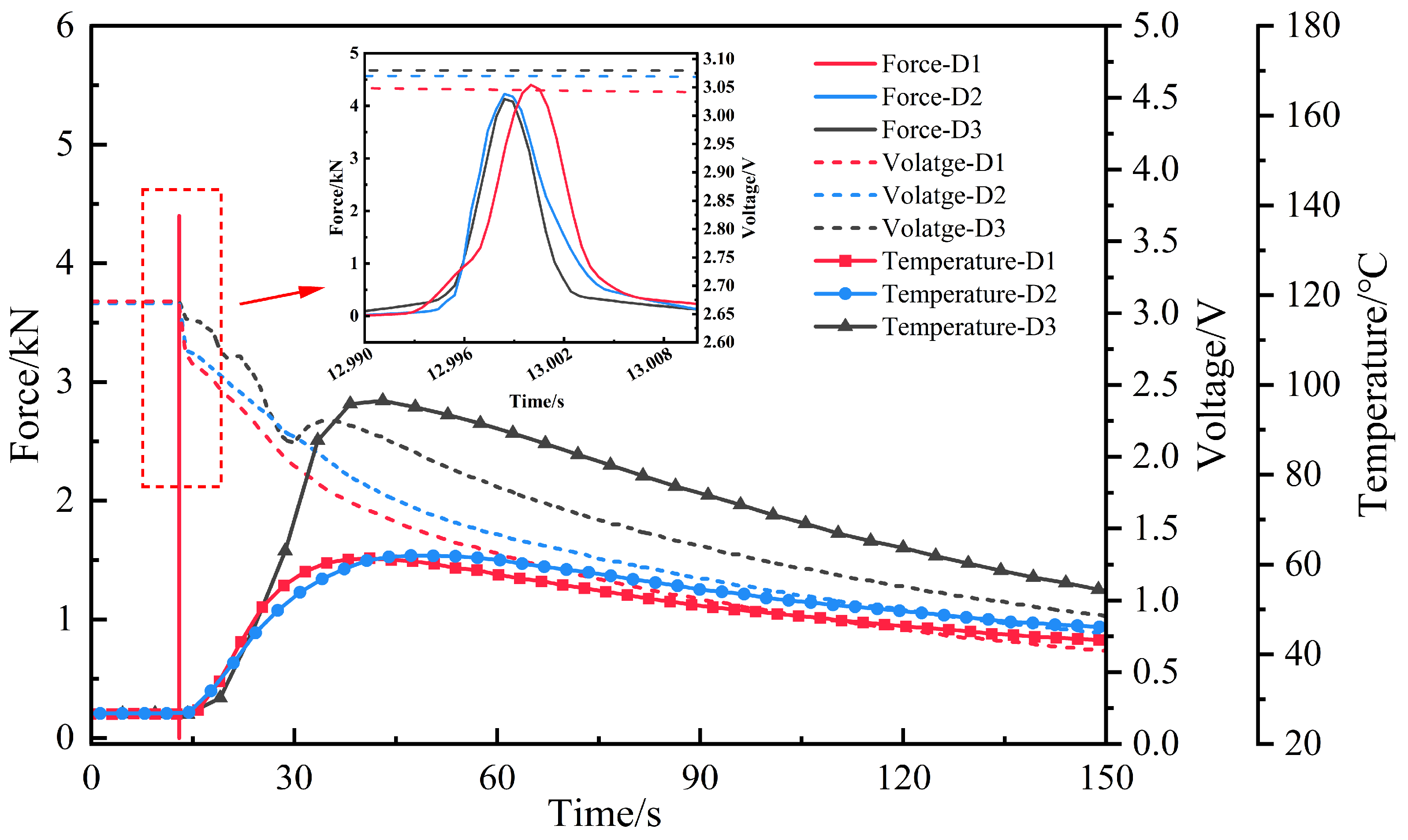
Figure 13.
Damage morphologies of battery cells in groups D1~D3 under different indenter diameters. (a) φ6 mm indenter in D1. (b) φ9 mm indenter in D1. (c) φ12.7 mm indenter in D1.
Figure 13.
Damage morphologies of battery cells in groups D1~D3 under different indenter diameters. (a) φ6 mm indenter in D1. (b) φ9 mm indenter in D1. (c) φ12.7 mm indenter in D1.
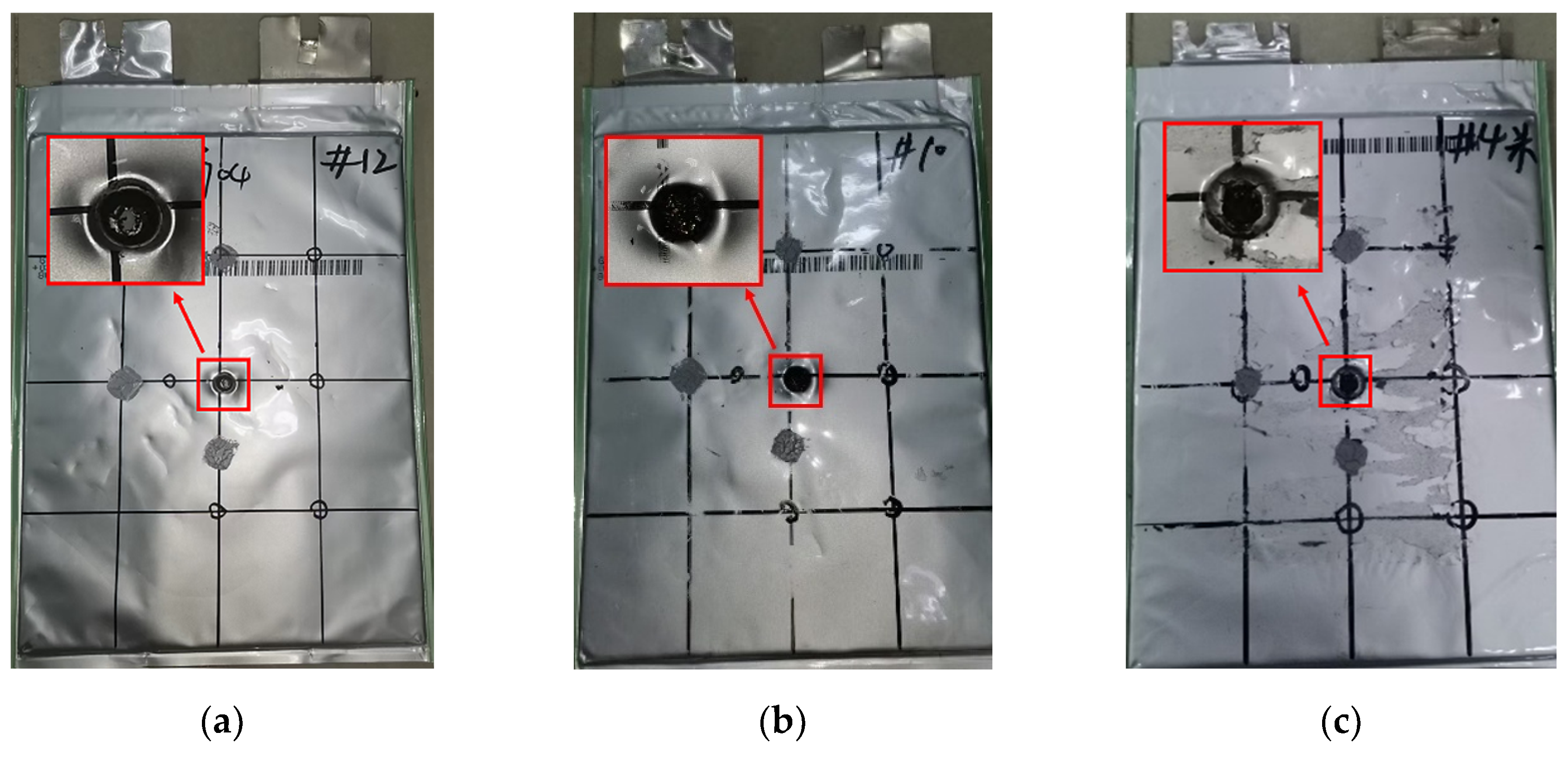
Figure 14.
Test results of groups D3, D7, and D8 under different impact velocities.
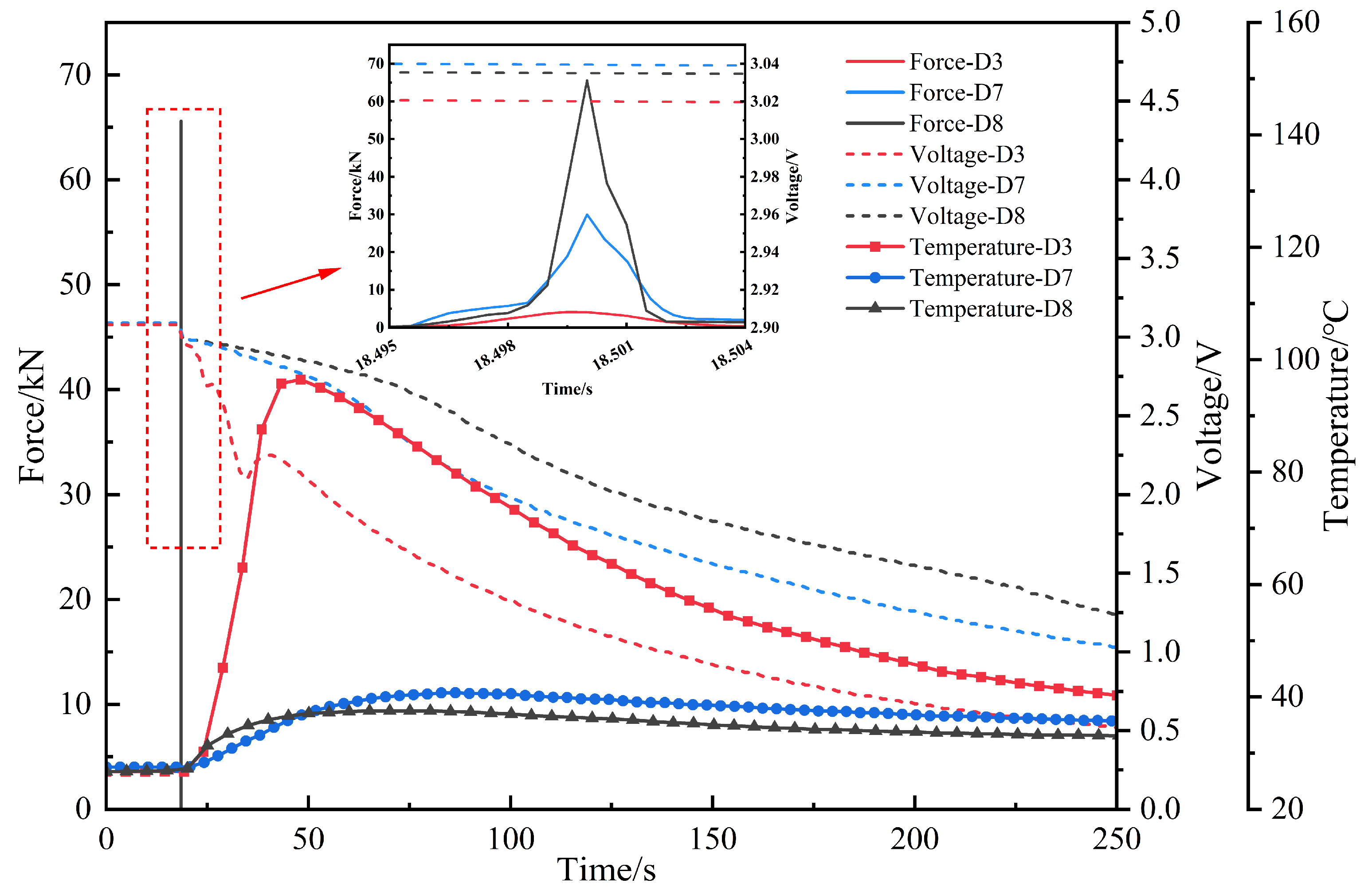
Figure 15.
Damage morphologies of battery cells in groups D1, D7, and D8 under different impact velocities (a) 1m/s in D3. (b) 3m/s in D3. (c) 5m/s in D3.
Figure 15.
Damage morphologies of battery cells in groups D1, D7, and D8 under different impact velocities (a) 1m/s in D3. (b) 3m/s in D3. (c) 5m/s in D3.
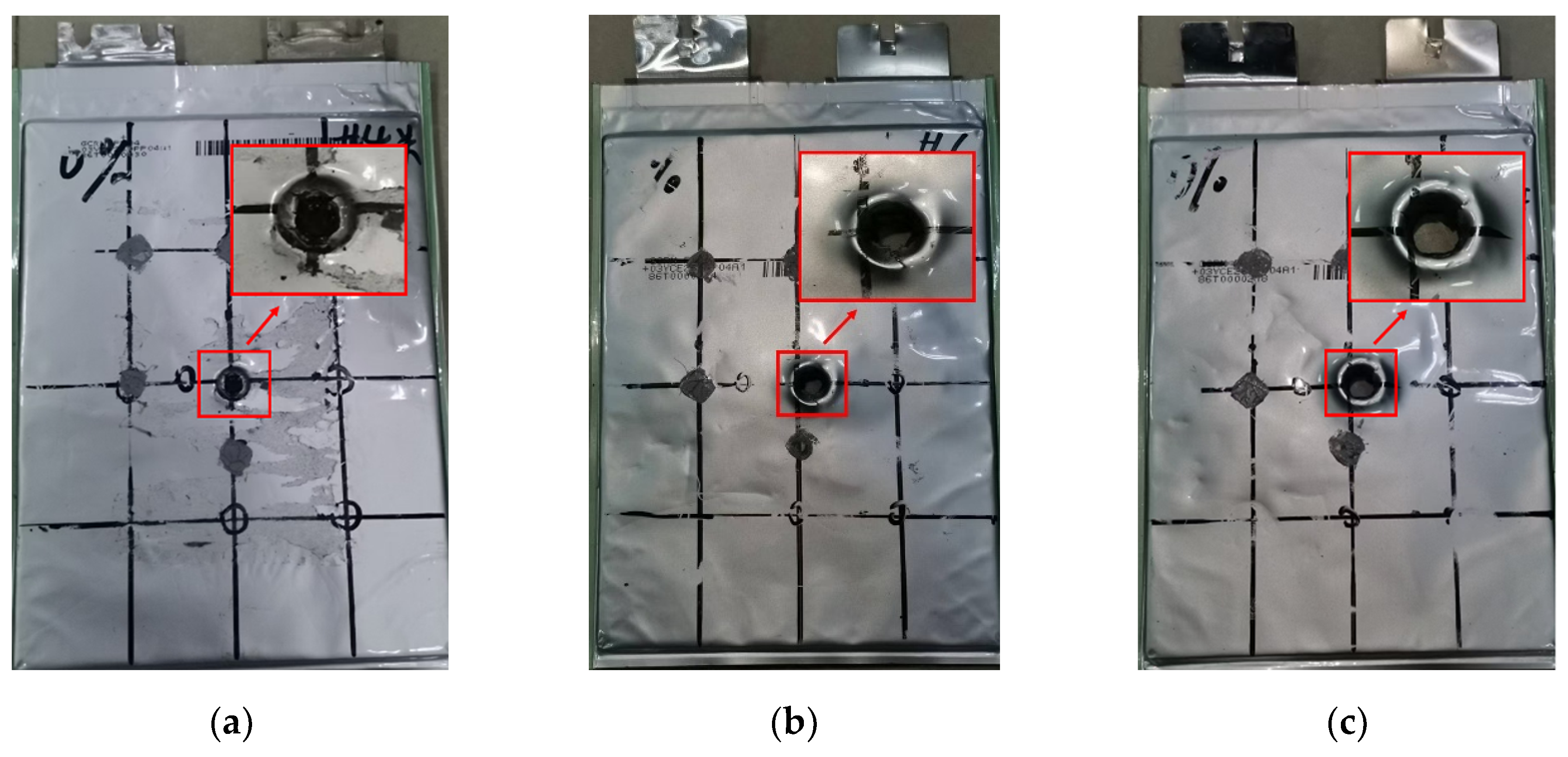
Figure 16.
Variations of voltage and temperature with time during drop-weight impact tests at different SOC. (a) Voltage response. (b) Temperature response.
Figure 16.
Variations of voltage and temperature with time during drop-weight impact tests at different SOC. (a) Voltage response. (b) Temperature response.
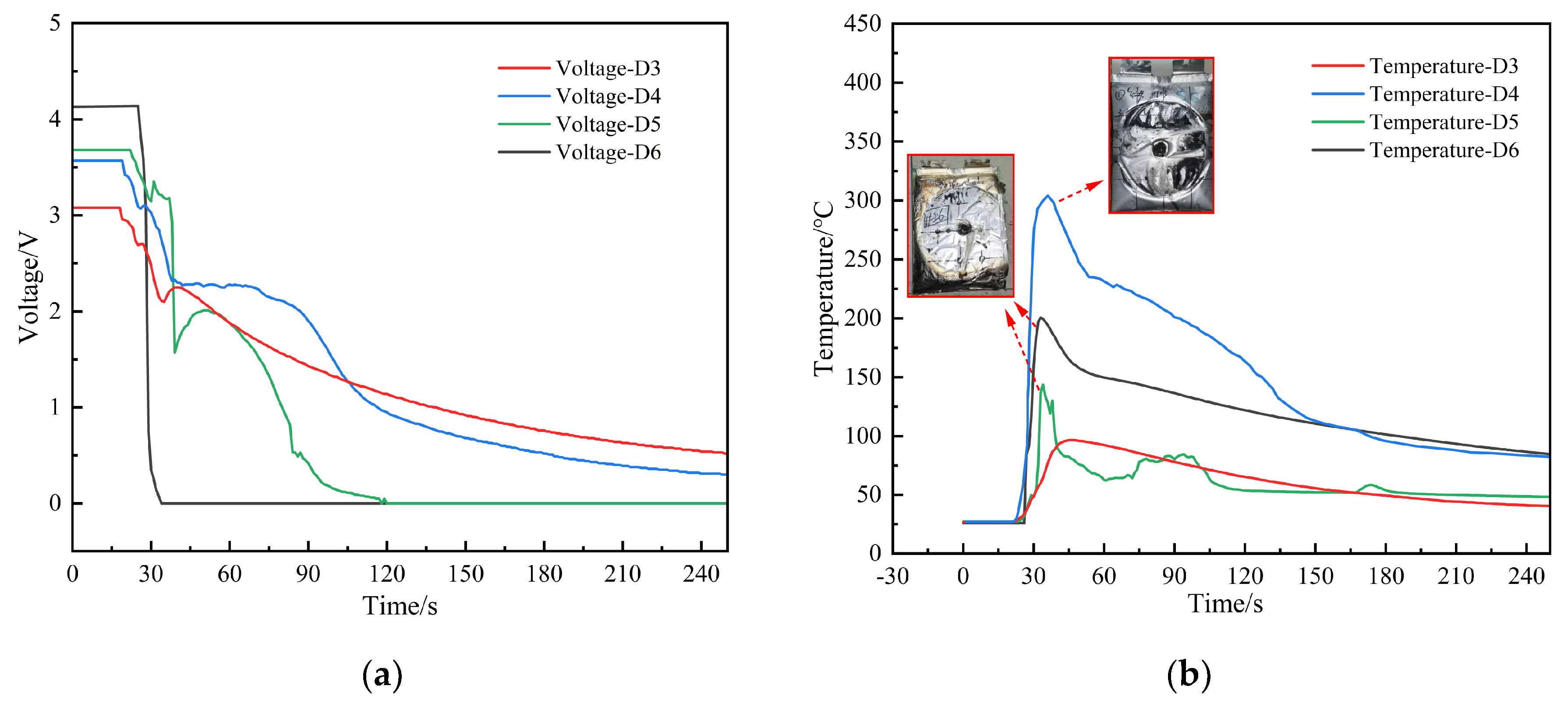
Figure 17.
Test process of 100% SOC battery cells in group D6. (a) Internal short circuit initiation. (b) Cell bulging. (c) Thermal runaway with flame ejection.
Figure 17.
Test process of 100% SOC battery cells in group D6. (a) Internal short circuit initiation. (b) Cell bulging. (c) Thermal runaway with flame ejection.
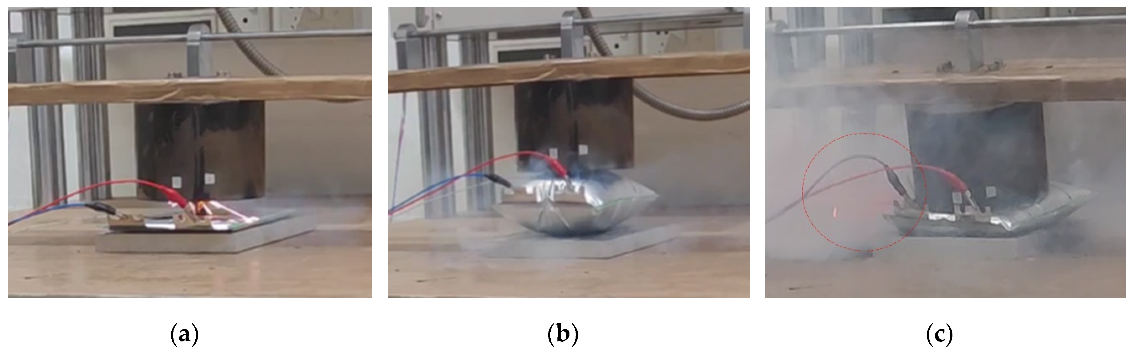
Figure 18.
Damaged morphologies of 100% SOC battery cells in group D6. (a) Localized crushing. (b) Packaging structure instability. (c) Side rupture and ablation.
Figure 18.
Damaged morphologies of 100% SOC battery cells in group D6. (a) Localized crushing. (b) Packaging structure instability. (c) Side rupture and ablation.
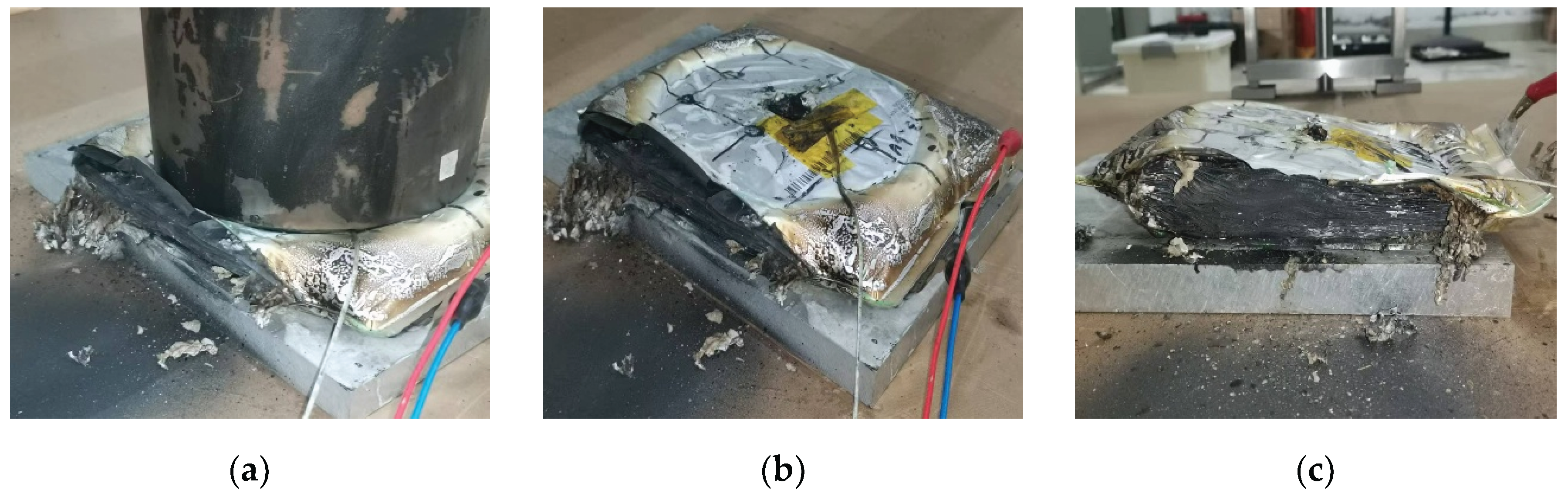
Figure 19.
Voltage-temperature comparison of tests Q3, Q4, D3, and D4. (a) Voltage response. (b) Temperature response.
Figure 19.
Voltage-temperature comparison of tests Q3, Q4, D3, and D4. (a) Voltage response. (b) Temperature response.
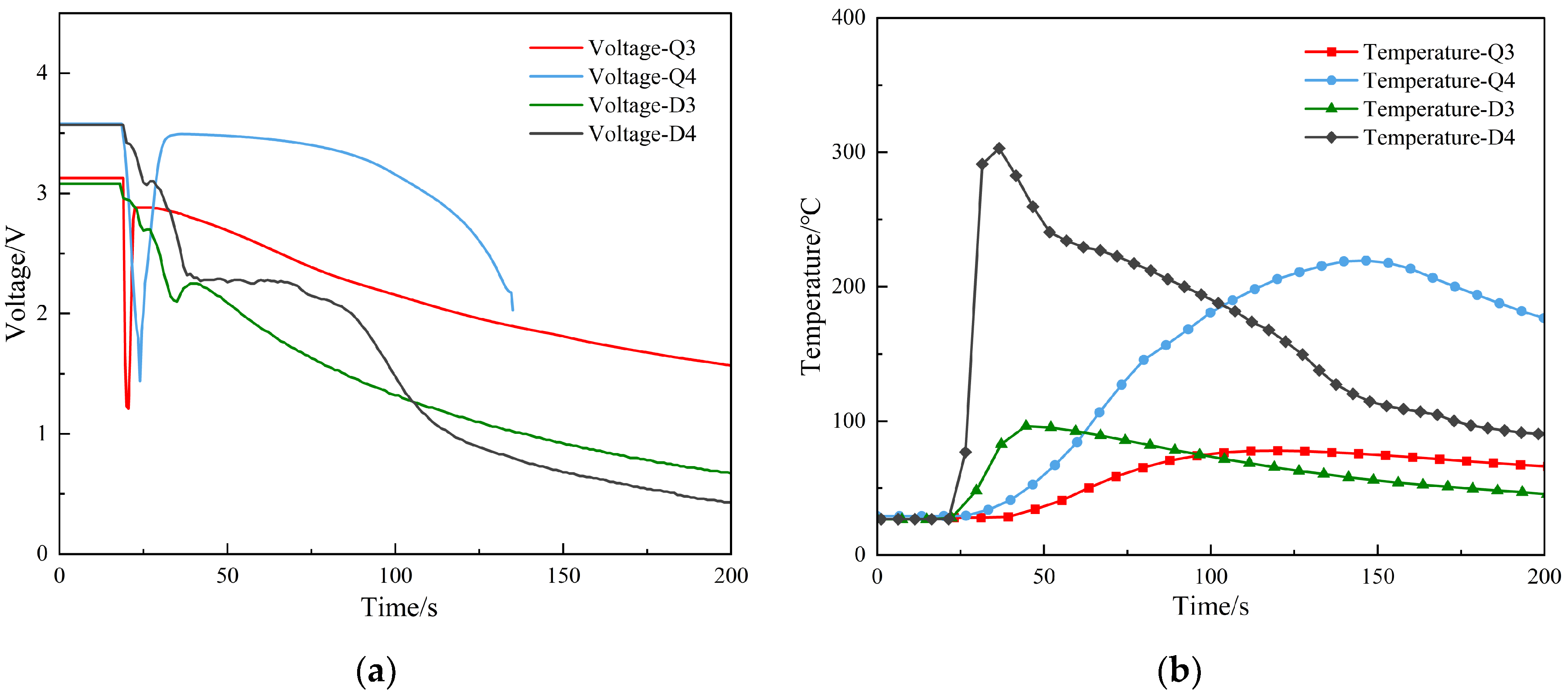

Table 1.
Quasi-static compression test parameter settings.
| Test group | Indenter diameter/mm | SOC/% |
| Q1 | 6.0 | 0 |
| Q2 | 9.0 | 0 |
| Q3 | 12.7 | 0 |
| Q4 | 6.0 | 20 |
| Q5 | 9.0 | 20 |
| Q6 | 12.7 | 20 |
Table 2.
Dynamic impact test parameter settings.
| Test group | Impact speed/(m⋅s-1) | Indenter diameter/mm | SOC/% |
| D1 | 1.0 | 6.0 | 0 |
| D2 | 1.0 | 9.0 | 0 |
| D3 | 1.0 | 12.7 | 0 |
| D4 | 1.0 | 12.7 | 20 |
| D5 | 1.0 | 12.7 | 50 |
| D6 | 1.0 | 12.7 | 100 |
| D7 | 3.0 | 12.7 | 0 |
| D8 | 5.0 | 12.7 | 0 |
Table 3.
Comparison of failure displacement, peak load force, and peak temperature of test groups Q1 to Q6.
Table 3.
Comparison of failure displacement, peak load force, and peak temperature of test groups Q1 to Q6.
| Test group | Indenter diameter /mm | SOC/% |
Failure displacement /mm |
Peak load force /kN |
Peak temperature /℃ |
| Q1 | 6.0 | 0 | 2.64 | 3.296 | 56.4 |
| Q4 | 20 | 2.74 | 3.414 | 70.4 | |
| Q2 | 9.0 | 0 | 3.56 | 7.273 | 59.1 |
| Q5 | 20 | 3.60 | 7.722 | 192.2 | |
| Q3 | 12.7 | 0 | 4.10 | 10.967 | 65.7 |
| Q6 | 20 | 4.15 | 11.517 | 219.6 |
Disclaimer/Publisher’s Note: The statements, opinions and data contained in all publications are solely those of the individual author(s) and contributor(s) and not of MDPI and/or the editor(s). MDPI and/or the editor(s) disclaim responsibility for any injury to people or property resulting from any ideas, methods, instructions or products referred to in the content. |
© 2026 by the authors. Licensee MDPI, Basel, Switzerland. This article is an open access article distributed under the terms and conditions of the Creative Commons Attribution (CC BY) license (http://creativecommons.org/licenses/by/4.0/).
Copyright: This open access article is published under a Creative Commons CC BY 4.0 license, which permit the free download, distribution, and reuse, provided that the author and preprint are cited in any reuse.


