

Submitted:
07 May 2026
Posted:
07 May 2026
You are already at the latest version
Abstract
Developing highly efficient, stable, and cost-effective non-precious metal electrocatalysts to replace traditional platinum-based materials is of great significance for advancing the commercialization of advanced energy conversion devices, such as zinc-air batteries (ZABs). Herein, we propose a facile and highly efficient strategy to successfully prepare a defect-rich, highly active nitrogen-doped porous carbon-based electrocatalyst, U-Fe-N-C (Urea-assisted synthesized iron-nitrogen-carbon material), via a high-temperature co-pyrolysis treatment of heme in the presence of urea. The study demonstrates that urea not only acts as an excellent nitrogen source during pyrolysis, introducing abundant topological defects and heteroatom doping sites, but also prompts the carbon substrate to form a hierarchical sponge-like porous structure with a high specific surface area. This unique microenvironment effectively prevents the agglomeration of iron species at high temperatures, achieving efficient anchoring and high dispersion of catalytic active centers. Electrochemical tests indicate that under optimal synthesis conditions (precursor mass ratio of 1:3, calcination at 900 °C), U-Fe-N-C exhibits outstanding oxygen reduction reaction (ORR) catalytic activity (with a half-wave potential reaching 0.731 V vs. RHE) and possesses long-term durability far exceeding that of commercial Pt/C. Furthermore, liquid rechargeable zinc-air batteries assembled with U-Fe-N-C as the air cathode demonstrate exceptional stability, achieving up to 270 h of charge-discharge cycling without attenuation. This study not only provides profound insights into the mechanisms of pore formation and assistance but also offers a novel perspective for the rational design and scalable synthesis of high-performance metal-nitrogen-carbon (M-N-C) electrocatalysts.
Keywords:
oxygen reduction reaction
; zinc-air batteries
; heme-derived carbon
; Fe-N-C electrocatalyst
1. Introduction
The escalating energy crisis and environmental pollution issues have accelerated the global development of clean and sustainable energy conversion and storage technologies [1]. Among them, ZABs are considered highly promising next-generation energy storage systems due to their high theoretical energy density, superb safety, and low cost. However, the large-scale application of ZABs is severely hindered by the sluggish kinetics of the oxygen reduction reaction and oxygen evolution reaction (OER) at the air cathode. Currently, although noble metal materials represented by Pt/C are the benchmark catalysts for ORR, their widespread application is greatly limited by exorbitant prices, scarce earth reserves, and issues, such as severe metal particle agglomeration and carbon support corrosion that readily occur during long-term cycling (especially in strong oxidizing environments with alternating charge and discharge) [2]. Therefore, exploring low-cost, highly active, and exceptionally stable non-precious metal electrocatalysts has become a critical challenge in this field.
Among numerous non-precious metal catalysts, transition metal-nitrogen-carbon (particularly Fe-N-C) materials have garnered significant attention owing to their superb intrinsic catalytic activity [3]. Heme, a natural iron porphyrin complex inherently containing Fe-N4 coordination centers and a rich carbon skeleton within its molecular structure, is an ideal precursor for synthesizing Fe-N-C catalysts. However, the direct high-temperature pyrolysis of pure heme often faces two major dilemmas: first, structural collapse readily occurs during carbonization, leading to an extremely low porosity in the product and impeding mass transfer processes [4]; second, the lack of effective physical confinement and additional coordination anchoring leads to the inevitable and severe agglomeration of iron species at high temperatures, forming large inactive metal clusters. This drastic reduction in the effective catalytic active sites exposed on the surface results in suboptimal overall electrocatalytic performance.
To overcome these bottlenecks, rational design and defect engineering of the micro-morphology of the carbon substrate are of paramount importance. The introduction of heteroatoms (e.g., N, S, P) can not only tune the electronic structure of the carbon skeleton and break electroneutrality to optimize the adsorption energy of intermediates but also increase topological defects, providing more coordination sites to anchor metal centers [5,6,7]. Concurrently, constructing a three-dimensional hierarchical porous network can effectively expand the specific surface area, expose deeper active sites, and provide ample high-speed channels for electrolyte infiltration and rapid O2 diffusion.
Upon this background, this work ingeniously introduces urea as a bifunctional additive to successfully design and synthesize a defect-rich, hierarchically porous Fe-N-C electrocatalyst, U-Fe-N-C, through simple mixing with heme followed by high-temperature anaerobic calcination. In this synthetic strategy, urea decomposes violently at high temperatures to produce copious amounts of gas (such as NH3 and CO2), playing a crucial role as an in situ bubble template to transform the initially dense heme-derived carbon into a loose, porous sponge-like structure [8,9]. Simultaneously, the introduced nitrogen-rich environment effectively increases the defect density of the carbon skeleton and suppresses the excessive agglomeration of iron species. Benefiting from the optimized pore network, high density of defect sites, and highly dispersed active centers, the optimal U-Fe-N-C catalyst exhibits ORR activity close to that of commercial Pt/C in alkaline media, along with extraordinary durability during long-term operation. More importantly, when applied in practical zinc-air batteries, the U-Fe-N-C-based air cathode achieves an ultra-long stable cycle life of 270 h, far surpassing conventional Pt/C catalysts. This study not only provides a highly feasible methodology for modifying heme-derived electrocatalysts but also serves as an important reference for the core material design of next-generation high-performance energy storage devices.
2. Materials and Methods
2.1. Chemical Reagents and Materials
Heme (97.1%) was purchased from Shanghai Aladdin Biochemical Technology Co., Ltd. Multi-walled carbon nanotubes (99%) were purchased from Shanghai Yuanye Bio-Technology Co., Ltd. Potassium chloride (analytical grade, 99.5%) and urea (analytical grade, 98.5%) were acquired from Shanghai Macklin Biochemical Co., Ltd. Ethanol (anhydrous) was purchased from Beijing Chemical Works. Isopropanol (analytical grade, 99.5%) was purchased from Shanghai Aladdin Biochemical Technology Co., Ltd. Nafion D520 dispersion (5%) was purchased from Alfa Aesar. Potassium hydroxide (analytical grade, 99.7%) was purchased from Shanghai Aladdin Biochemical Technology Co., Ltd. Hydrochloric acid (analytical grade) and nitric acid (analytical grade) were purchased from Beijing Chemical Works. Zinc acetate (analytical grade) was purchased from Xilong Scientific Co., Ltd. Hydrophobic carbon paper was purchased from Shanghai Hesen Electrical Co., Ltd. All water used in the experiments was deionized water with a resistivity of 18.25 MΩ·cm, produced by a Unique-R20 system. All chemicals were commercially available and used directly without further purification.
2.2. Physical Characterization
X-ray powder diffraction (XRD, Siemens D5005 diffractometer) was employed to analyze the composition and crystal structure of the samples, using Cu-Kα radiation (λ = 1.5418 Å, 30 mA, 40 kV) with a scanning angle range of 5° to 80° and a scanning speed of 5° min-1. Prior to testing, powder samples were compacted in a glass groove to maintain a flat surface. Transmission electron microscopy (TEM, JEM-2100F) was used to observe the morphology of the samples at an accelerating voltage of 200 kV. The samples were dispersed in ethanol, and 2 μL of the dispersion was dropped onto a double-grid copper mesh for testing. A Raman spectrometer (LabRAM XploRA, HORIBA) was utilized to characterize the presence and structural features of graphitized carbon in the samples. A small amount of the ground powder sample was evenly spread on a glass slide and pressed into a thin layer, followed by blowing away loose surface particles with an ear-washing bulb. A 532 nm laser was used as the excitation light source for signal acquisition, with a scanning range from 400 to 2000 cm-1.
2.3. Catalyst Preparation
Initially, heme and urea were placed in a mortar at a mass ratio of 1:3, and a small amount of anhydrous ethanol was added, followed by thorough grinding for 10 min to ensure uniform mixing. The ground mixture was dried in an oven at 40 °C and subsequently transferred to a porcelain boat. The porcelain boat was placed in a tube furnace and heated to 900 °C at a heating rate of 5 °C min-1 under an N2 atmosphere, maintaining this temperature for 2 h. After naturally cooling to room temperature, the resulting product was extracted and ground again to obtain the final catalyst product (Figure 1).
2.4. Electrochemical Characterization
Catalyst ink was first prepared: 5 mg of the catalyst sample was weighed and added to a mixed solvent consisting of 760 μL of deionized water, 190 μL of isopropanol, and 50 μL of Nafion reagent. Uniform dispersion was achieved through sonication for 30 min. Subsequently, 10 μL of the dispersion was evenly drop-cast onto the surface of a glassy carbon electrode with a diameter of 5 mm, which served as the working electrode. All electrochemical measurements were performed at room temperature using a conventional three-electrode system on a CHI660E electrochemical workstation. A rotating disk electrode (RDE) served as the working electrode, a graphite rod acted as the counter electrode, and an Ag/AgCl electrode was used as the reference electrode in the alkaline environment.
Cyclic voltammetry (CV) tests were conducted in a 0.1 M KOH electrolyte saturated with sufficient O2, with the potential range set from 0.2 V to -0.8 V and a scan rate of 10 mV s-1. To evaluate the ORR activity of the catalysts, linear sweep voltammetry (LSV) curves were recorded using the RDE setup in the same O2-saturated 0.1 M KOH electrolyte. The LSV scan rate was set to 5 mV s−1, the potential range remained from 0.2 V to -0.8 V, and polarization curves were recorded as the rotation speed varied from 400 rpm to 1600 rpm. Additionally, to assess the electrocatalytic stability of the catalyst, chronoamperometry (i-t) tests were performed at a constant rotation speed of 1600 rpm.
The electron transfer number n and the kinetic current density jk during the reaction were calculated using the Koutecký-Levich (K-L) equations:
where j is the measured current density, and jk represents the kinetic current density; ω corresponds to the angular velocity of the RDE; F is the Faraday constant (96,485 C mol-1); the parameters C0 and D0 are the bulk concentration and diffusion coefficient of O2, respectively; and v represents the kinematic viscosity of the electrolyte, which is 0.01 cm2 s-1.
All potential data involved in this experiment were uniformly converted to the reversible hydrogen electrode (RHE) potential using the following equation:
ERHE = EAg/AgCl + 0.059pH+0.197
2.5. Zinc-Air Battery Assembly and Testing
In the assembly of the liquid zinc-air battery, the lab-made catalyst material was used for device construction. The overall battery configuration was as follows: a polished zinc plate was used as the anode, a polished copper plate as the cathode, and a 6.0 M KOH alkaline solution containing 0.2 M Zn(Ac)2 as the electrolyte. For the air electrode, the specific preparation method involved uniformly drop-casting the aforementioned dispersed target catalyst (or commercial Pt/C catalyst) onto the surface of hydrophobic carbon paper, controlling the loading amount to 1 mg mL-1.
The polarization curve data of the battery were collected via the CHI660E workstation, with a scanning rate set to 5 mV s-1. Furthermore, the galvanostatic charge-discharge cycling stability test was performed on the LAND CT2001A battery testing system. The specific test conditions were: the current density was maintained at 10 mA cm-2, each charge-discharge cycle period was set to 20 min, and the battery rested for 10 min before formal cycling. The specific capacity of the battery was calculated using the following formula:
In this formula, I represents the applied current (mA), t represents the operation time (h), and refers to the mass of zinc consumed during the reaction (g).
3. Results
The morphology of the heme-derived carbon materials is illustrated in Figure 2 Regardless of whether urea was assisted, the materials exhibit irregular morphologies with an average particle size of approximately 400 nm. Figure 2a and b displays the TEM images of the carbon material obtained by direct high-temperature pyrolysis of the heme precursor without urea treatment. It can be observed that the surface of the pure heme-derived carbon is relatively smooth, presenting a rather dense, block-like morphology. As seen from Figure 2b, its internal carbon skeleton is relatively continuous, locally accompanied by a small amount of short-range ordered graphitic lattice fringes, and the overall porosity is low. Upon introducing urea, the microscopic morphology of the material undergoes significant changes. As shown in Figure 2c and d, the carbon material achieved in the presence of urea and subjected to high-temperature pyrolysis exhibits a rough, sponge-like porous structure with obvious wrinkles. This is primarily attributed to the violent decomposition of urea in the high-temperature anaerobic environment, which releases a large amount of gas (such as NH3, CO, and CO2), acting as an in situ pore-forming agent during the formation of the carbon substrate.
To explore into the impact of the urea-assisted strategy on the pore evolution and internal structure of heme-derived carbon materials, N2 adsorption-desorption isotherm, X-ray diffraction, and Raman spectroscopy were collected. As shown in Figure 3a-d, although the isotherm of the un-assisted sample also exhibits a certain hysteresis loop (which may primarily originate from a small amount of internal mesopores generated during pyrolysis or stacking pores between nanoparticles), an intuitive comparison of the adsorption volume and pore size distribution curves reveals that the overall specific surface area and pore volume of the un-assisted system remain at a low level, with an extremely broad pore size distribution. In contrast, after introducing urea, the pore structure of the material is further optimized (Figure 3c, d), which is highly consistent with the rough, sponge-like porous morphology observed in the aforementioned TEM images. The gases released by urea during high-temperature pyrolysis not only promote the generation of mesopores but also effectively regulate the pore size distribution of the carbon substrate [10,11]. This optimized hierarchical porous structure can significantly reduce the diffusion resistance of electrolyte ions, thereby accelerating mass transfer kinetics during the electrocatalytic process. Compared with the pure heme sample, the U-Fe-N-C sample exhibits a certain degree of broadening and a relative decrease in peak intensity for the carbon (002) diffraction peak near 26° (Figure 3e). This indicates that the gases and nitrogen-rich environment released by urea during high-temperature pyrolysis effectively disrupt the long-range ordered graphitization process, hindering the regular stacking of carbon layers. This reduction in crystallinity implies that more abundant amorphous carbon and topological defects are generated within the material. Due to the lack of external anchoring sites, the pure heme sample is highly susceptible to severe agglomeration of iron species at high temperatures, leading to sharp and complex metal crystalline diffraction peaks in the 40°–50° range [12,13,14]. In contrast, in the U-Fe-N-C pattern, the relative sharpness and aggregation morphology of these metal diffraction peaks fundamentally change. This strongly proves that urea, as a high-quality nitrogen source, achieves nitrogen doping during pyrolysis, and the generated nitrogen-containing groups can effectively coordinate with free iron atoms (forming potential Fe-N-C configurations). This strong interaction limits the excessive growth and agglomeration of iron nanoparticles, promoting the metal active centers to be anchored in the porous carbon skeleton with smaller sizes and higher dispersion [13,14], thereby substantially increasing the exposure density and utilization of active sites in the electrocatalyst [15]. As shown in Figure 3f, all samples exhibit typical D bands (representing amorphous or defect carbon structures) and G bands (representing sp2-hybridized graphitic carbon) at 1350 cm−1 and 1580 cm−1, respectively. By calculating the intensity ratio of the D band to the G band [16,17,18], the defect degree of the materials can be intuitively quantified. The ID/IG value of pure heme-derived carbon is only 0.54, indicating a high degree of graphitization and fewer defects. As the proportion of urea assistance increases, the ID/IG value of the material rises significantly (reaching a maximum of 1.45 at a ratio of 1:3). This prominent trend strongly demonstrates that urea acts not only as a pore-forming agent but also as an effective nitrogen source, successfully introducing an abundance of topological defects and heteroatom doping sites (such as edge defects, vacancies, and nitrogen-containing groups) into the carbon lattice [12,19,20]. These high-density defect sites induced by urea can effectively break electroneutrality, optimize the adsorption energy of intermediates, and are widely recognized as the key to enhancing the electrocatalytic activity of materials.
Figure 4a displays the LSV polarization curves of carbon materials derived from different mass ratios of heme to urea (1:0.5, 1:1.5, 1:3, 1:6) at the same pyrolysis temperature. It can be clearly observed that with the increase in the proportion of urea assistance, the ORR catalytic activity of the material shows a trend of initially increasing and then decreasing. When the ratio of heme to urea is 1:3, the catalyst exhibits the most excellent ORR performance, featuring the most positive onset potential (Eonset), half-wave potential (E1/2), and the maximum diffusion-limited current density. This electrochemical testing result is highly consistent with the preceding Raman spectroscopic analysis (the highest ID/IG value at the 1:3 ratio). This indicates that an appropriate amount of urea can not only construct a well-developed porous network but also introduce the maximum density of intrinsic carbon defects and heteroatom doping sites (such as nitrogen-containing active groups), thereby maximizing charge transfer efficiency and reaction kinetics. However, when the proportion of urea is excessively high (e.g., 1:6), excessive gas-phase etching may lead to carbon skeleton collapse, decreased conductivity, or excessive consumption of active sites, thereby causing the catalytic performance to decline. Simultaneously, the pyrolysis temperature plays a decisive role in the graphitization degree, pore evolution, and retention of doping elements in carbon-based materials. Based on establishing the optimal precursor ratio (1:3), Figure 4b further investigates the effect of different pyrolysis temperatures (800 °C, 900 °C, 1000 °C) on ORR performance. The results show that the sample calcined at 900 °C exhibits the best electrocatalytic activity. This is primarily attributed to 900 °C providing an excellent equilibrium point: it ensures a sufficiently high degree of graphitization of the carbon skeleton to provide outstanding electrical conductivity, while simultaneously avoiding the massive volatilization of effective assisted nitrogen species and the sintering and collapse of the mesoporous structure caused by excessively high temperatures (e.g., 1000 °C). Conversely, at a lower temperature of 800 °C, incomplete carbonization leads to poor conductivity of the material, and the metal active centers may not be fully evolved and exposed, thus exhibiting extremely low catalytic current.
To systematically elucidate the specific electrochemical behavior of the optimally synthesized U-Fe-N-C catalyst prior to benchmarking against commercial standards, CV was initially employed As shown in Figure 5a, the U-Fe-N-C catalyst solely exhibits a characteristic flat electrical double-layer capacitive background current in the N2-saturated electrolyte; whereas in the O2-saturated electrolyte, a highly distinct cathodic reduction peak appears at approximately 0.65 V (vs. RHE), intuitively proving that the material possesses significant electrocatalytic activity for the oxygen reduction reaction. As depicted in the linear sweep voltammetry curves in Figure 5b and the half-wave potential bar chart in Figure 5c, the ORR performance of the pure heme material is highly limited (E1/2 is only 0.521 V), which is mainly attributed to its lower porosity and scarcity of catalytic active sites. In contrast, the performance of the urea-assisted U-Fe-N-C catalyst achieves a qualitative leap, with its half-wave potential substantially elevated to 0.731 V, and a significantly increased diffusion-limited current density. This exceptional performance not only far exceeds that of pure heme-derived materials but also closely approaches the level of the commercial Pt/C catalyst (E1/2 = 0.758 V). This surge in performance is credited to the rich mesoporous network formed by urea templating (accelerating mass transfer) and the abundant defects introduced by nitrogen doping. As confirmed by extensive research, such a nitrogen-rich microenvironment can effectively anchor free iron atoms, forming metal-nitrogen (Fe-N-C) active centers with superb ORR activity [13,14]. To further explore the electron transfer mechanism of U-Fe-N-C catalyzed ORR, its LSV curves were tested at varying RDE speeds (400-1600 rpm) (Figure 5d). With increasing rotation speed, the electrolyte diffusion distance shortens, and the limiting current density exhibits a regular gradient increase. The K-L plots (Figure 5e) drawn based on these data exhibit a good linear relationship between j-1 and ω-1/2. This indicates that the oxygen reduction reaction occurring on the surface of the catalyst features obvious first-order reaction kinetics and suggests that it follows an efficient dominant high-electron-transfer-number (close to 4-electron) pathway, capable of effectively reducing O2 directly to OH−, thereby minimizing the generation of harmful intermediates (such as H2O2) [21,22,23,24]. Long-term stability is another critical metric for evaluating the practical application value of electrocatalysts. As shown by the constant-potential chronoamperometry test in Figure 5f, after 5000 s of continuous operation, the U-Fe-N-C catalyst still maintains 90.1% of its initial current density. In contrast, the current density of the commercial Pt/C catalyst plummets to 69.4% under identical conditions. The outstanding durability exhibited by U-Fe-N-C is primarily due to its robust porous carbon skeleton structure, which effectively prevents the agglomeration, dissolution, and detachment of active centers (such as metal nanoparticles or single-atom sites) during long-term electrolysis.
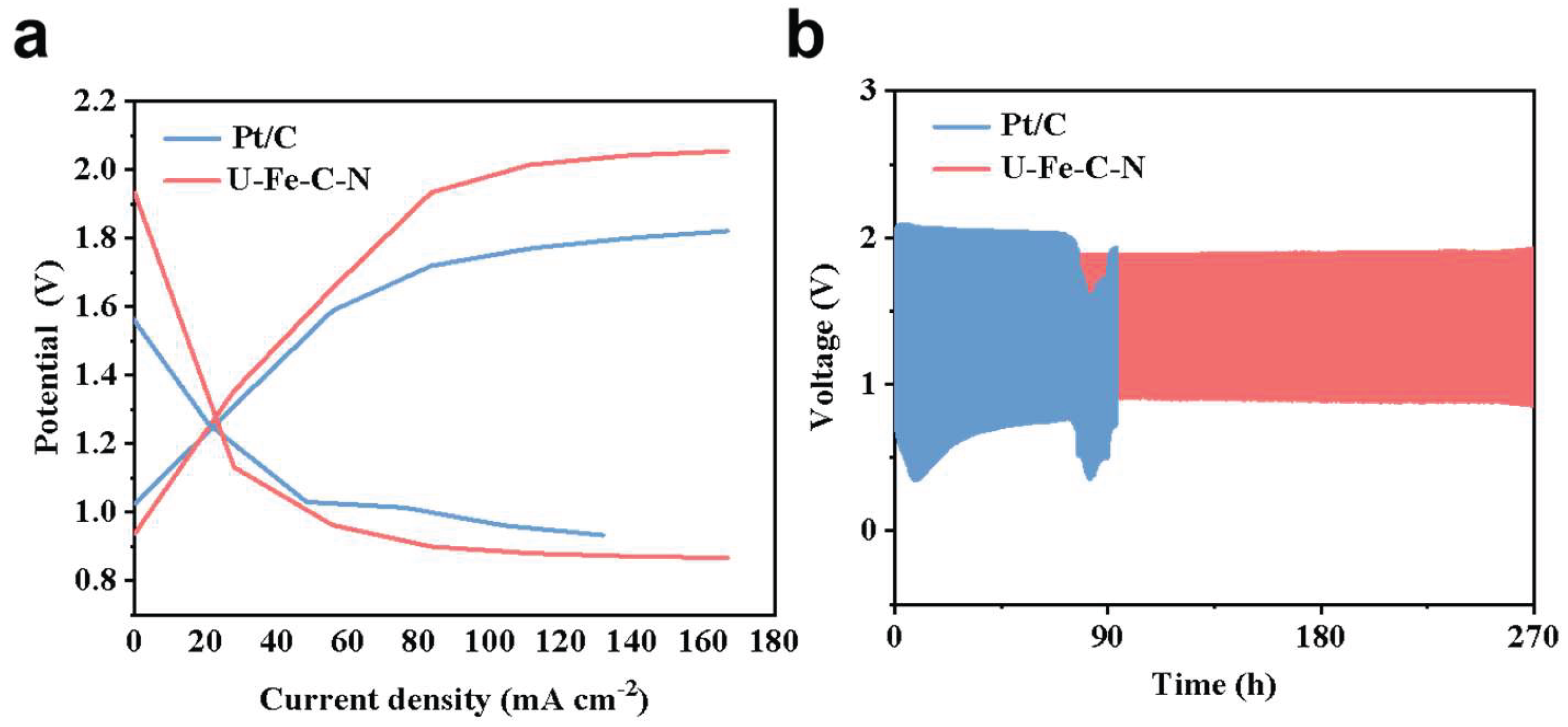
To further evaluate the practical application potential of the electrocatalyst in real energy conversion devices, liquid rechargeable zinc-air batteries were assembled and tested. Although commercial Pt/C exhibits a narrower voltage gap in the initial stage, U-Fe-N-C still demonstrates a stable working voltage plateau and excellent polarization behavior at high current densities (Figure 6a), confirming its practicality as a bifunctional air cathode for rechargeable zinc-air batteries. During the long-term galvanostatic charge-discharge testing, the Pt/C battery rapidly degrades and fails after operating for about 90 h due to carbon corrosion and metal particle detachment at high oxidation potentials [25]. Distinct from the rapid failure of Pt/C, U-Fe-N-C exhibits superb durability, achieving a stable cycle of up to 270 h, with the charge-discharge voltage gap remaining narrow and without significant attenuation (Figure 6b). This remarkable stability demonstrated in the practical device powerfully corroborates the previously mentioned structural advantages: the urea-assisted derived porous and defect-rich carbon skeleton not only significantly promotes reaction mass transfer but also effectively anchors and protects the internal active sites, shielding them from erosion in harsh environments with alternating redox conditions. [2,26,27,28].
4. Discussion
The successful synthesis of the U-Fe-N-C electrocatalyst validates our working hypothesis that utilizing urea as a bifunctional additive can effectively overcome the inherent limitations of direct heme pyrolysis. While previous studies on pure heme-derived carbons often reported structural collapse and severe metal agglomeration, our results demonstrate that high-temperature co-pyrolysis with urea induces an in situ bubble-templating effect alongside a nitrogen-rich environment. This dual action not only creates a hierarchical sponge-like porous structure but also facilitates the formation of highly dispersed Fe-N-C active centers, directly addressing the common challenges of low porosity and inactive metal clustering. Consequently, the optimized U-Fe-N-C catalyst exhibited a half-wave potential of 0.731 V and long-term durability that significantly exceeds that of commercial Pt/C.
In a broader context, the findings of this study provide critical insights into how defect engineering and pore regulation can synergistically enhance electrocatalytic performance. As global energy demands accelerate the need for cost-effective and robust energy storage systems like zinc-air batteries, the reliance on scarce and expensive noble metals remains a primary bottleneck. Our facile, urea-assisted methodology offers a highly scalable and sustainable alternative, transforming naturally abundant iron porphyrin complexes into premium metal-nitrogen-carbon electrocatalysts. Furthermore, the ultra-long 270 h cycling stability demonstrated in practical liquid zinc-air batteries highlights the viability of this material under realistic, harsh alternating redox conditions.
Future research should focus on elucidating the precise atomic-level configuration of the Fe-N coordination environments within this defect-rich carbon matrix to further optimize intrinsic activity. Additionally, translating these porous air-cathode materials into solid-state or flexible zinc-air battery architectures will be a vital next step toward expanding their commercial application in wearable electronics and other next-generation energy storage devices.
5. Conclusions
In summary, this work successfully developed a highly efficient electrocatalyst preparation strategy utilizing natural heme and urea as precursors. Through high-temperature anaerobic co-pyrolysis, urea exerts a dual function of in situ pore generation and nitrogen doping, which not only endows the carbon skeleton with a hierarchical porous sponge-like structure but also introduces abundant topological defects and heteroatom anchoring sites. This unique microscopic environment effectively overcomes the severe agglomeration issue of iron species typical in traditional pyrolysis processes, facilitating the formation of highly dispersed and high-density catalytic active centers. Electrochemical investigations reveal that the optimized U-Fe-N-C catalyst exhibits remarkable ORR activity in alkaline media and possesses long-term durability far superior to that of commercial Pt/C. Furthermore, when employed as the air cathode in liquid rechargeable zinc-air batteries, the device demonstrates outstanding charge-discharge cycling stability. This study not only provides a profound revelation of the intrinsic mechanisms by which defect engineering and pore regulation synergistically enhance electrocatalytic performance but also offers practical guiding principles for the rational design and scalable synthesis of high-performance, cost-effective M-N-C catalytic materials for next-generation energy storage systems.
Acknowledgments
This work is financially supported by Jilin Provincial Science and Technology Development Foundation (Grant No. 20250102063JC) and the 14th Five-Year Plan in Science and Technology of the Education Department of Jilin Province (JJKH20211018KJ).
References
- Song, R.; Guan, L.; Fan, L.; Miao, X.; Zhang, H.; Cheng, J.; Zhou, T.; Ni, C.; Fan, J. Metal-Organic-Framework-Derived Fe, Co, N-Tri-Dopped Porous Carbon as Oxygen Electrocatalysts for Zn-Air Batteries. J. Energy Storage 2024, 80, 110345. [Google Scholar] [CrossRef]
- Chen, K.; Sun, W.; Huang, J.; Gao, J.; Liang, Y.; Lu, Z.; Cai, P.; Chen, J.; Zhang, H.; Wen, Z. Batch Preparation of Fe Single-Atom Catalysts for Ultrahigh Power Density Zinc-Air Batteries. CCS Chem. 2025, 7, 1844–1855. [Google Scholar] [CrossRef]
- Tadavani, K. F.; Zhiani, M.; Gharibi, H.; Dehkordi, H. B. Preparation of a High-Performance Fe–N–C Electrocatalyst from an MOF Precursor for ORR Toward Zinc–Air Batteries. Energy Fuels 2023, 37, 19092–19102. [Google Scholar] [CrossRef]
- Yabu, H.; Ishibashi, K.; Grewal, M. S.; Matsuo, Y.; Shoji, N.; Ito, K. Bifunctional Rare Metal-Free Electrocatalysts Synthesized Entirely from Biomass Resources. Sci. Technol. Adv. Mater. 2022, 23, 31–40. [Google Scholar] [CrossRef]
- Zhao, Z.; Chen, H.; Zhang, W.; et al. Defect Engineering in Carbon Materials for Electrochemical Energy Storage and Catalytic Conversion. Mater. Adv. 2023, 4, 835–867. [Google Scholar] [CrossRef]
- Zhang, J.; Zhang, J.; He, F.; Chen, Y.; Zhu, J.; Wang, D.; Mu, S.; Yang, H. Y. Defect and Doping Co-Engineered Non-Metal Nanocarbon ORR Electrocatalyst. Nano-Micro Lett. 2021, 13, 65. [Google Scholar] [CrossRef]
- Jiang, Y.; Yang, L.; Sun, T.; Zhao, J.; Lyu, Z.; Zhuo, O.; Wang, X.; Wu, Q.; Ma, J.; Hu, Z. Significant Contribution of Intrinsic Carbon Defects to Oxygen Reduction Activity. ACS Catal. 2015, 5, 6707–6712. [Google Scholar] [CrossRef]
- Yan, L.; Liu, Y.; Hou, J. High-Efficiency Oxygen Reduction Reaction Revived from Walnut Shell. Molecules 2023, 28, 2072. [Google Scholar] [CrossRef]
- Caldera, A.; Escobar, B.; Briceño, J.; Baas-López, J. M.; Barbosa, R.; Uribe, J. Nitrogen-Doped Biocarbon Derived from Alginate-Extraction Residues of Sargassum Spp.: Towards Low-Cost Electrocatalysts for Alkaline ORR. Chemistry 2025, 7, 144. [Google Scholar] [CrossRef]
- Gómez-Serrano, V.; González-Garcı́a, C. M.; González-Martı́n, M. L. Nitrogen Adsorption Isotherms on Carbonaceous Materials. Comparison of BET and Langmuir Surface Areas. Powder Technol. 2001, 116, 103–108. [Google Scholar] [CrossRef]
- Sun, F.; Liu, J.; Chen, H.; Zhang, Z.; Qiao, W.; Long, D.; Ling, L. Nitrogen-Rich Mesoporous Carbons: Highly Efficient, Regenerable Metal-Free Catalysts for Low-Temperature Oxidation of H2S. ACS Catal. 2013, 3, 862–870. [Google Scholar] [CrossRef]
- Ilnicka, A.; Lukaszewicz, J. P.; Shimanoe, K.; Yuasa, M. Urea Treatment of Nitrogen-Doped Carbon Leads to Enhanced Performance for the Oxygen Reduction Reaction. J. Mater. Res. 2018, 33, 1612–1624. [Google Scholar] [CrossRef]
- George, S. L.; Zhao, L.; Wang, Z.; Xue, Z.; Zhao, L. Iron Porphyrin-Based Composites for Electrocatalytic Oxygen Reduction Reactions. Molecules 2024, 29, 5655. [Google Scholar] [CrossRef]
- Shilpa, N.; Wu, J.-X.; Waterhouse, G.; Zhu, B.; Travas-Sejdic, J.; Williams, D. Biomass Electrocatalysts: Exploiting Haemoglobin-Derived Fe Sites Coordinated with S, N-Enriched Carbon for Efficient Oxygen Electro-Reduction. ChemRxiv 2024. [Google Scholar] [CrossRef]
- Lai, Q.; Zheng, L.; Liang, Y.; He, J.; Zhao, J.; Chen, J. Metal–Organic-Framework-Derived Fe-N/C Electrocatalyst with Five-Coordinated Fe-Nx Sites for Advanced Oxygen Reduction in Acid Media. ACS Catal. 2017, 7, 1655–1663. [Google Scholar] [CrossRef]
- Mao, Z.; Fu, Y.; Long, X.; Li, C.; Li, M.; Zhu, F.; Ye, W.; Fan, Z.; Yao, X. Carbon-Based Materials for Electrocatalytic Energy Conversion: From Understanding to Designing. Chem. Synth. 2025, 5, N/A-N/A. [Google Scholar] [CrossRef]
- Flores-Lasluisa, J. X.; Cazorla-Amorós, D.; Morallón, E. Deepening the Understanding of Carbon Active Sites for ORR Using Electrochemical and Spectrochemical Techniques. Nanomaterials 2024, 14, 1381. [Google Scholar] [CrossRef] [PubMed]
- Wu, Q.; Yan, X.; Jia, Y.; Yao, X. Defective Carbon-Based Materials: Controllable Synthesis and Electrochemical Applications. EnergyChem 2021, 3, 100059. [Google Scholar] [CrossRef]
- Yang, X.; Gao, X.; Zheng, Y.-X.; Kuang, H.; Chen, C.-F.; Liu, M.; Duan, P.; Tang, Z. Recent Progress of Circularly Polarized Luminescence Materials from Chinese Perspectives. CCS Chem. 2023, 5, 2760–2789. [Google Scholar] [CrossRef]
- He, G.; Yan, G.; Song, Y.; Wang, L. Biomass Juncus Derived Nitrogen-Doped Porous Carbon Materials for Supercapacitor and Oxygen Reduction Reaction. Front. Chem. 2020, 8. [Google Scholar] [CrossRef]
- Lyu, L.; Hu, X.; Lee, S.; Fan, W.; Kim, G.; Zhang, J.; Zhou, Z.; Kang, Y.-M. Oxygen Reduction Kinetics of Fe–N–C Single Atom Catalysts Boosted by Pyridinic N Vacancy for Temperature-Adaptive Zn–Air Batteries. J. Am. Chem. Soc. 2024, 146, 4803–4813. [Google Scholar] [CrossRef] [PubMed]
- Shao, M.; Chang, Q.; Dodelet, J.-P.; Chenitz, R. Recent Advances in Electrocatalysts for Oxygen Reduction Reaction. Chem. Rev. 2016, 116, 3594–3657. [Google Scholar] [CrossRef] [PubMed]
- Bocchetta, P.; Sánchez, C. R.; Taurino, A.; Bozzini, B. Accurate Assessment of the Oxygen Reduction Electrocatalytic Activity of Mn/Polypyrrole Nanocomposites Based on Rotating Disk Electrode Measurements, Complemented with Multitechnique Structural Characterizations. J. Anal. Methods Chem. 2016, 2016, 1–16. [Google Scholar] [CrossRef]
- Molina-García, M. A.; Rees, N. V. Effect of Catalyst Carbon Supports on the Oxygen Reduction Reaction in Alkaline Media: A Comparative Study. RSC Adv. 2016, 6, 94669–94681. [Google Scholar] [CrossRef]
- Peera, S. G.; Kim, S.-W.; Ashmath, S.; Lee, T.-G. Sustainable Fe3C/Fe-Nx-C Cathode Catalyst from Biomass for an Oxygen Reduction Reaction in Alkaline Electrolytes and Zinc–Air Battery Application. Inorganics 2025, 13, 143. [Google Scholar] [CrossRef]
- Yan, Y.; Liang, S.; Wang, X.; Zhang, M.; Hao, S.-M.; Cui, X.; Li, Z.; Lin, Z. Robust Wrinkled MoS2 /N-C Bifunctional Electrocatalysts Interfaced with Single Fe Atoms for Wearable Zinc-Air Batteries. Proc. Natl. Acad. Sci. 2021, 118, e2110036118. [Google Scholar] [CrossRef]
- Jin, H.; Yu, R.; Ji, P.; Zeng, W.; Li, Z.; He, D.; Mu, S. Sharply Expanding Single-Atomically Dispersed Fe–N Active Sites through Bidirectional Coordination for Oxygen Reduction. Chem. Sci. 2024, 15, 7259–7268. [Google Scholar] [CrossRef]
- Li, Y.-W.; Zhang, W.-J.; Li, J.; Ma, H.-Y.; Du, H.-M.; Li, D.-C.; Wang, S.-N.; Zhao, J.-S.; Dou, J.-M.; Xu, L. Fe-MOF-Derived Efficient ORR/OER Bifunctional Electrocatalyst for Rechargeable Zinc–Air Batteries. ACS Appl. Mater. Interfaces 2020, 12, 44710–44719. [Google Scholar] [CrossRef]
Figure 1.
Schematic illustration of the catalyst synthesis process.
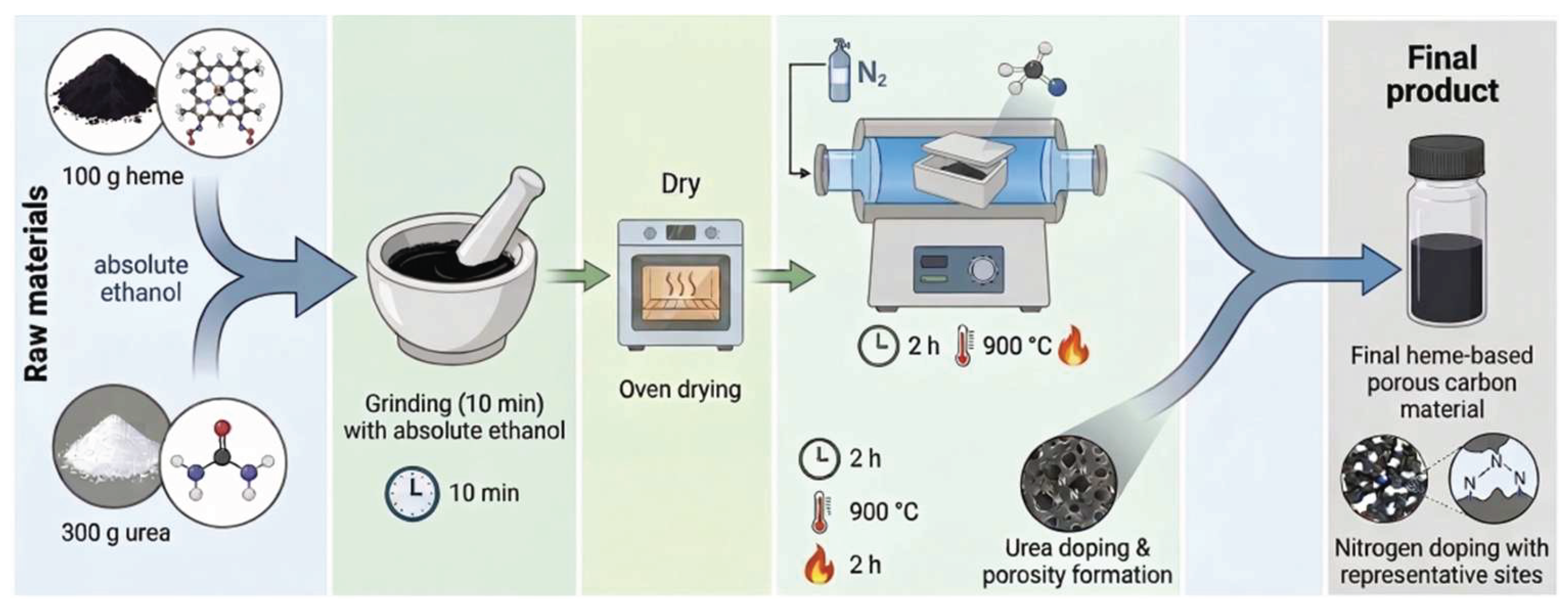
Figure 2.
Morphological characterization of heme-derived carbon materials. (a, b) TEM images of the un-assisted heme-derived carbon material; (c, d) TEM images of the urea-assisted heme-derived porous carbon material.
Figure 2.
Morphological characterization of heme-derived carbon materials. (a, b) TEM images of the un-assisted heme-derived carbon material; (c, d) TEM images of the urea-assisted heme-derived porous carbon material.
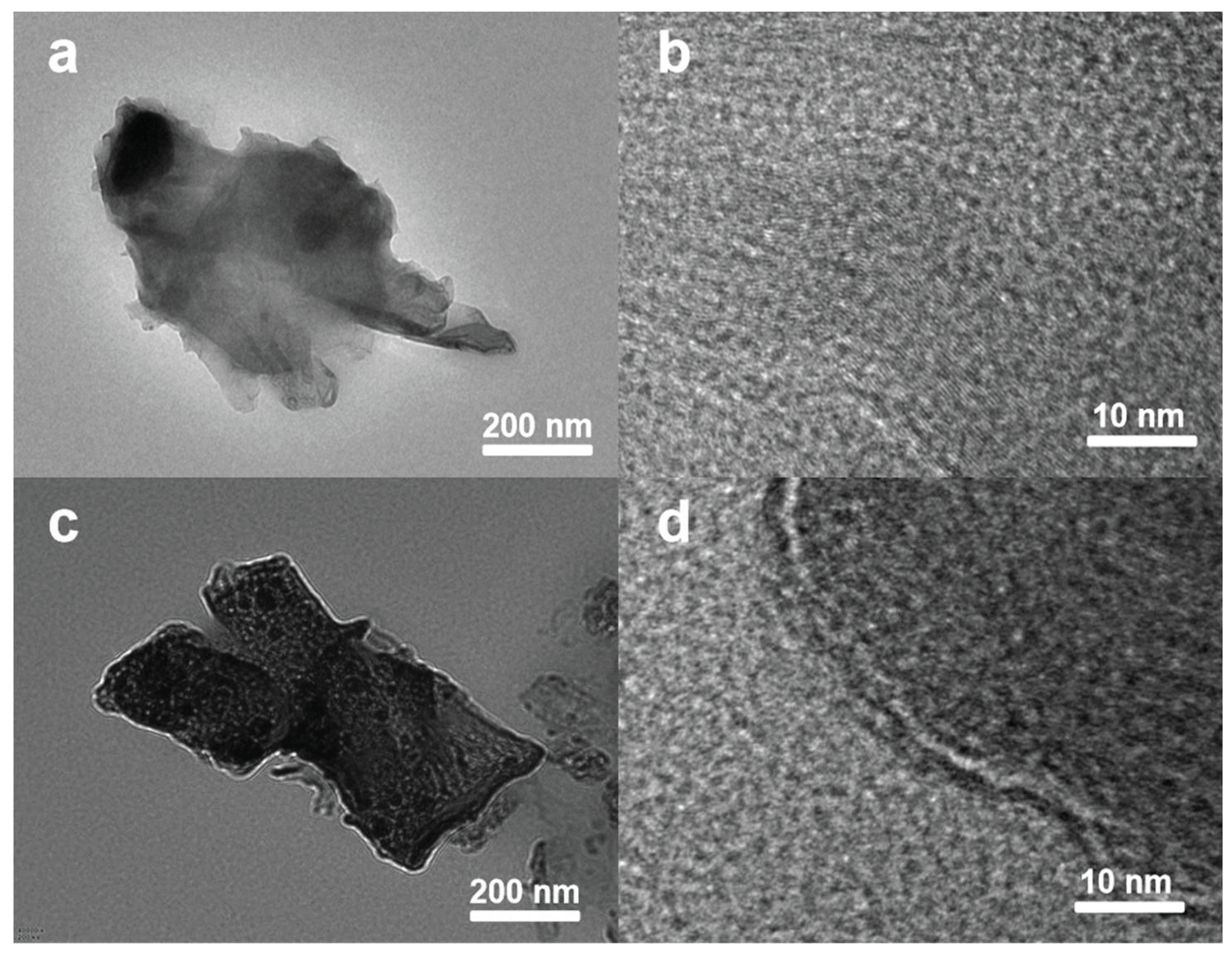
Figure 3.
Structural and phase characterization of un-assisted and urea-assisted heme-derived carbon materials at varying ratios. (a, b) N2 adsorption-desorption isotherms and pore size distribution curves of the un-assisted samples; (c, d) N2 adsorption-desorption isotherms and pore size distribution curves of the urea-assisted samples; (e) XRD patterns of un-assisted (heme) and urea-assisted (U-Fe-N-C) samples; (f) Raman spectra and corresponding ID/IG values of the carbon materials obtained after pyrolysis of precursors with different mass ratios of heme to urea.
Figure 3.
Structural and phase characterization of un-assisted and urea-assisted heme-derived carbon materials at varying ratios. (a, b) N2 adsorption-desorption isotherms and pore size distribution curves of the un-assisted samples; (c, d) N2 adsorption-desorption isotherms and pore size distribution curves of the urea-assisted samples; (e) XRD patterns of un-assisted (heme) and urea-assisted (U-Fe-N-C) samples; (f) Raman spectra and corresponding ID/IG values of the carbon materials obtained after pyrolysis of precursors with different mass ratios of heme to urea.
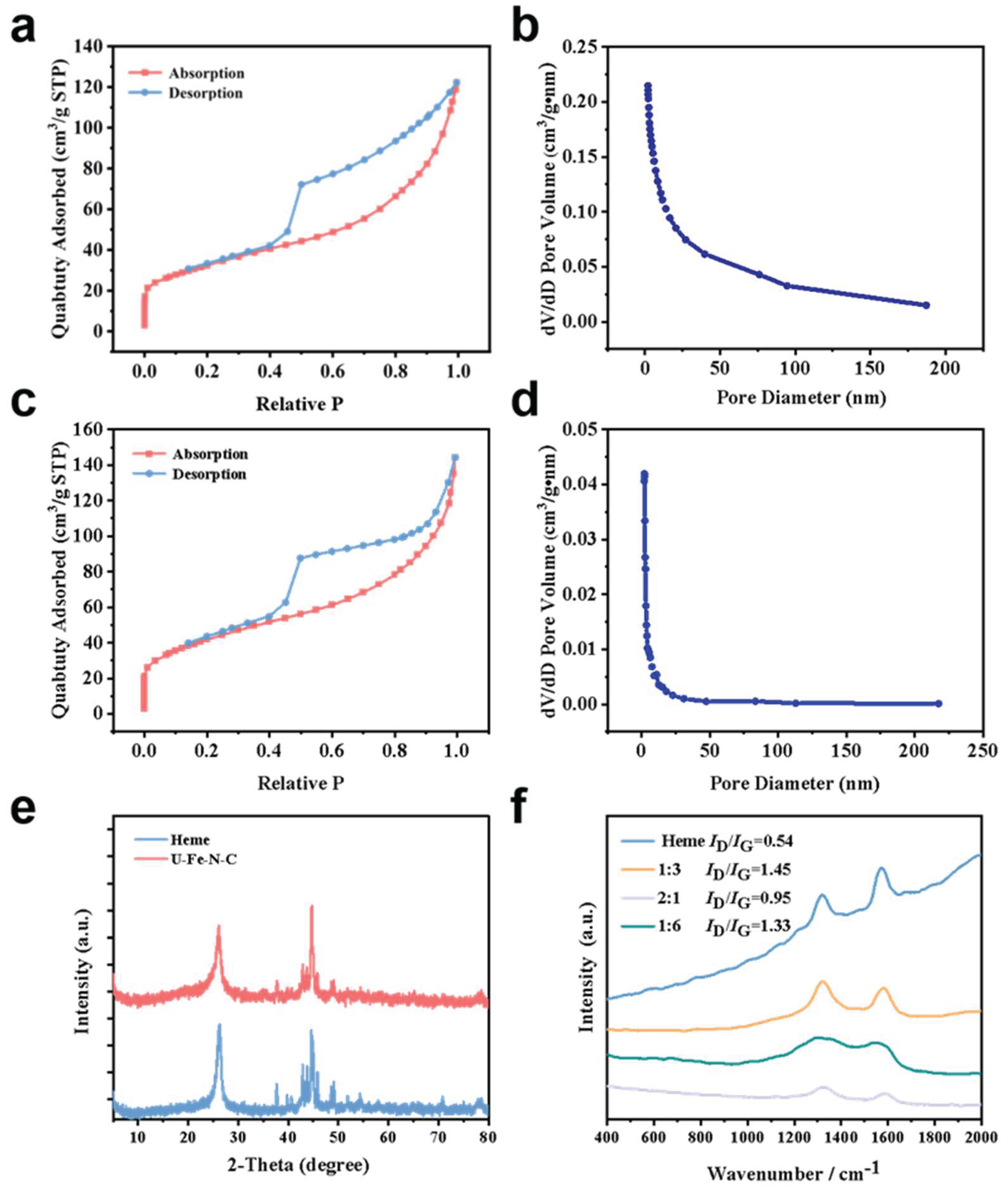
Figure 4.
Optimization of the ORR performance of heme-derived carbon materials. (a) LSV curves with different heme-to-urea assistance ratios; (b) LSV curves at different pyrolysis temperatures.
Figure 4.
Optimization of the ORR performance of heme-derived carbon materials. (a) LSV curves with different heme-to-urea assistance ratios; (b) LSV curves at different pyrolysis temperatures.
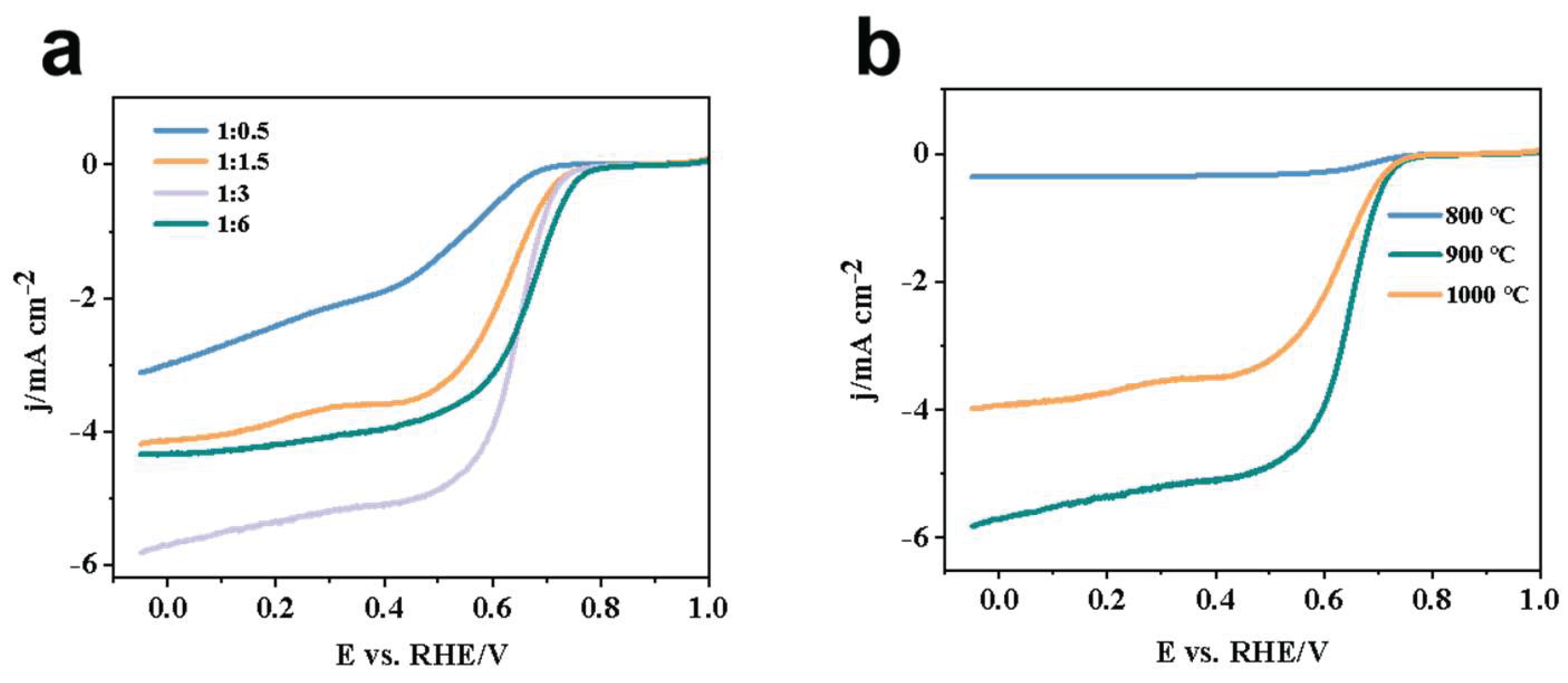
Figure 5.
ORR performance comparison and kinetic studies of the optimized U-Fe-N-C catalyst against other benchmark materials. (a) CV curves of the U-Fe-N-C catalyst in N2- and O2-saturated 0.1 M KOH electrolyte; (b) LSV polarization curves of heme, U-Fe-N-C, and commercial Pt/C catalysts at a rotation speed of 1600 rpm; (c) Comparison bar chart of the E1/2 for different catalysts; (d) LSV curves of the U-Fe-N-C catalyst at varying RDE rotation speeds (400 - 1600 rpm); (e) K-L plots corresponding to different potentials; (f) Chronoamperometric i-t stability test curves of U-Fe-N-C and Pt/C catalysts in 0.1 M KOH electrolyte.
Figure 5.
ORR performance comparison and kinetic studies of the optimized U-Fe-N-C catalyst against other benchmark materials. (a) CV curves of the U-Fe-N-C catalyst in N2- and O2-saturated 0.1 M KOH electrolyte; (b) LSV polarization curves of heme, U-Fe-N-C, and commercial Pt/C catalysts at a rotation speed of 1600 rpm; (c) Comparison bar chart of the E1/2 for different catalysts; (d) LSV curves of the U-Fe-N-C catalyst at varying RDE rotation speeds (400 - 1600 rpm); (e) K-L plots corresponding to different potentials; (f) Chronoamperometric i-t stability test curves of U-Fe-N-C and Pt/C catalysts in 0.1 M KOH electrolyte.
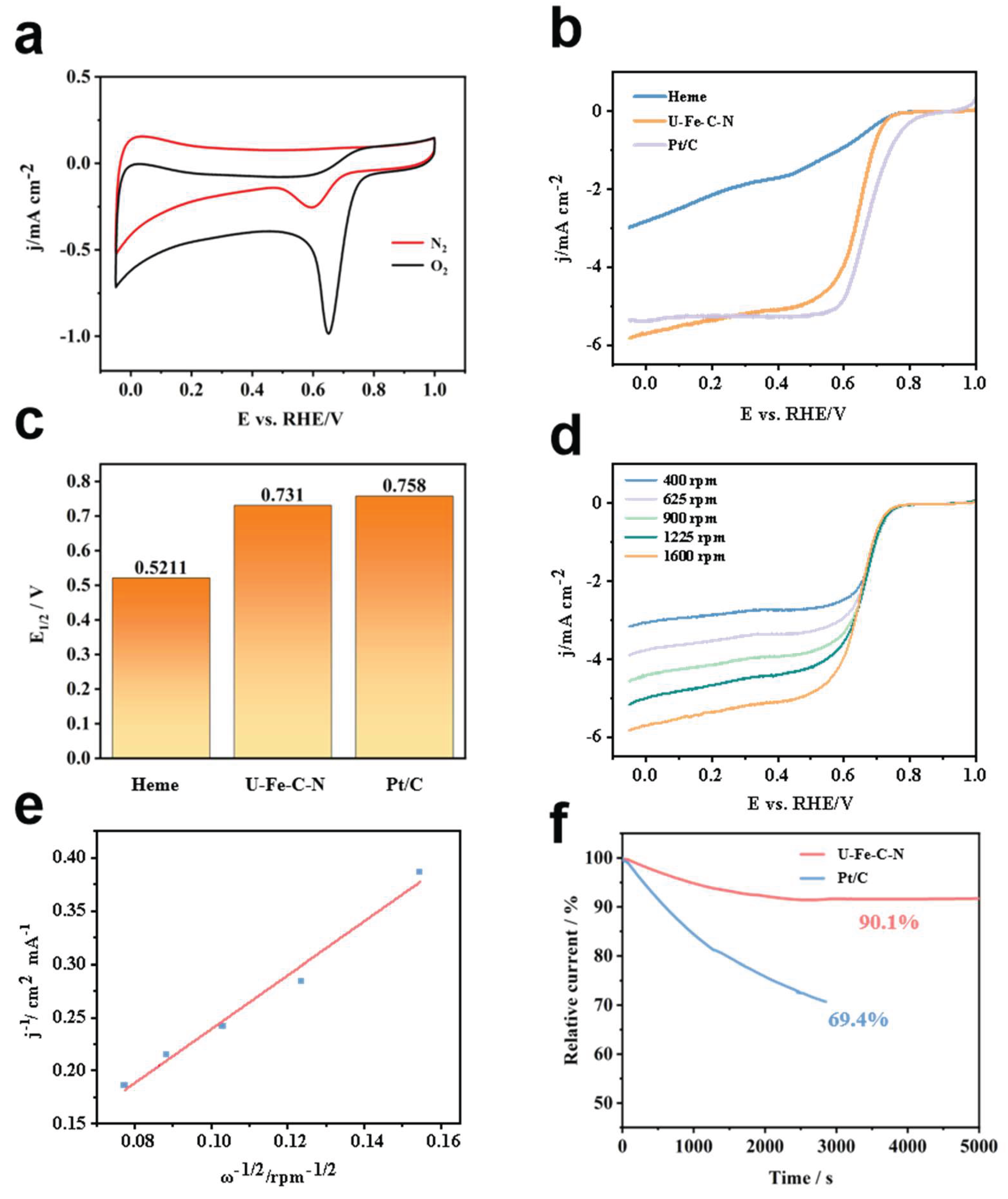
Figure 6.
Comparison of the performance of liquid zinc-air batteries assembled with heme-derived U-Fe-N-C and commercial Pt/C catalysts. (a) Charge and discharge polarization curves of the zinc-air batteries at different current densities; (b) Long-term galvanostatic charge-discharge cycling test curves of the zinc-air batteries at a constant current density.
Figure 6.
Comparison of the performance of liquid zinc-air batteries assembled with heme-derived U-Fe-N-C and commercial Pt/C catalysts. (a) Charge and discharge polarization curves of the zinc-air batteries at different current densities; (b) Long-term galvanostatic charge-discharge cycling test curves of the zinc-air batteries at a constant current density.
Disclaimer/Publisher’s Note: The statements, opinions and data contained in all publications are solely those of the individual author(s) and contributor(s) and not of MDPI and/or the editor(s). MDPI and/or the editor(s) disclaim responsibility for any injury to people or property resulting from any ideas, methods, instructions or products referred to in the content. |
© 2026 by the authors. Licensee MDPI, Basel, Switzerland. This article is an open access article distributed under the terms and conditions of the Creative Commons Attribution (CC BY) license (http://creativecommons.org/licenses/by/4.0/).
Copyright: This open access article is published under a Creative Commons CC BY 4.0 license, which permit the free download, distribution, and reuse, provided that the author and preprint are cited in any reuse.