

Submitted:
06 May 2026
Posted:
07 May 2026
You are already at the latest version
Abstract
During atmospheric reentry, a spacecraft is enveloped by a turbulent plasma sheath that induces severe signal degradation and communication blackout. Conventional mitigation strategies primarily focus on reducing average attenuation but fail to address the dynamic fluctuations in plasma density (typically 20%–40%), which cause significant group velocity dispersion (GVD), pulse broadening, and intersymbol interference. To overcome this limitation, this paper proposes an active decoupling framework that dynamically tunes an external magnetic field to suppress turbulence-induced signal distortion in the reentry plasma sheath. By establishing a wave propagation model for right-hand circularly polarized (RCP) waves in magnetized collisional plasma and introducing a sensitivity analysis of propagation parameters with respect to plasma density fluctuations, we derive the condition under which the first-order sensitivity of GVD vanishes. Under this condition, a dynamic balance between collisional effects and frequency detuning renders the system immune to density perturbations, effectively decoupling signal transmission from plasma turbulence. Numerical simulations demonstrate that, under optimal parameter matching, pulse broadening is suppressed by several orders of magnitude, and the broadening factor remains near unity over extended propagation distances. Furthermore, reentry trajectory analysis reveals that static matching is insufficient in dynamically evolving environments, motivating the necessity of adaptive magnetic field control. This work provides a novel physical-layer paradigm for mitigating reentry blackout by actively decoupling signals from turbulence via dynamically tuned magnetic fields.
Keywords:
reentry plasma sheath
; signal-turbulence decoupling
; group velocity dispersion
; dispersion immunity
; reentry blackout mitigation
1. Introduction
During atmospheric reentry, hypersonic vehicles (e.g., spacecraft and hypersonic missiles) experience intense aerodynamic heating due to severe friction with the surrounding air, which ionizes the ambient gas and leads to the formation of a plasma sheath enveloping the vehicle [1,2]. When the plasma frequency exceeds the communication carrier frequency, incident electromagnetic waves are either reflected or strongly absorbed, resulting in a communication outage lasting from several minutes to over ten minutes, commonly referred to as the “radio blackout” phenomenon [3,4]. Since the 1960s, the blackout problem has persistently challenged the aerospace community, posing severe threats to attitude control, telemetry transmission, Global Positioning System (GPS) navigation, and the reception of emergency commands [5,6]. With the rapid advancement of reusable launch vehicles and hypersonic weapon systems, mitigating reentry communication disruptions has become a critical technological challenge in aerospace engineering [7,8].
To alleviate the blackout effect, a variety of mitigation strategies have been proposed. Conventional approaches include increasing the carrier frequency into the terahertz (THz) band [9,10], injecting electronegative gases to reduce electron density or applying pulsed electric fields to actively deplete free electrons [11,12], and optimizing the aerodynamic configuration of the vehicle to reduce the thickness of the plasma layer [13]. Among these, the application of an external static magnetic field to form a “magnetic window,” which exploits the birefringence properties of magnetized plasma to enable transmission at specific frequencies, has emerged as a highly promising non-intrusive solution [14,15]. However, due to the nonuniform evolution of the magnetic field within the plasma sheath and the complex characteristics of hypersonic flow fields, the practical transmission performance of magnetic windows is often significantly constrained [16,17].
A more fundamental challenge arises from the intrinsically strong turbulence of the reentry plasma sheath [18]. Large spatiotemporal fluctuations in plasma density (typically on the order of 20%–40%) modulate the refractive index and dispersion characteristics, thereby inducing severe parasitic modulation effects [19,20]. This dynamically time-varying behavior leads to fluctuations in group velocity dispersion (GVD) for broadband signals, resulting in pronounced pulse broadening, enhanced intersymbol interference (ISI), and substantial degradation in phase demodulation performance [21,22]. Existing magnetic-field-based mitigation strategies primarily focus on reducing static average attenuation, while the issues of deep fading and bit error rate (BER) degradation under the coupled effects of dynamic plasma fluctuations and external magnetic fields have not yet been systematically addressed [23,24]. This limitation significantly constrains achievable data rates and overall system reliability.
To overcome these limitations, this paper proposes an anti-turbulence transmission framework based on right-hand circularly polarized (RCP) wave propagation in magnetized plasma. Departing from conventional attenuation-oriented strategies, we adopt a dispersion engineering perspective and systematically characterize the response of group velocity dispersion (GVD) to plasma density fluctuations via sensitivity analysis. It is revealed that under specific parameter-matching conditions, a dynamic balance between collisional effects and frequency detuning suppresses the first-order sensitivity of GVD, placing the system in a dispersion-immune regime where turbulence-induced pulse broadening and intersymbol interference are significantly mitigated. Furthermore, the external magnetic field provides tunable degrees of freedom—via cyclotron frequency and propagation angle—enabling joint optimization that achieves stable, low-distortion signal transmission in the microwave band while avoiding strong absorption.
2. Theoretical Model
2.1. Wave Propagation and Sensitivity Analysis
A plane electromagnetic wave with angular frequency is considered to propagate quasi-longitudinally in a homogeneous magnetized cold plasma. The external static magnetic field is assumed to be , and the angle between the wave vector and is denoted by . In a magnetized plasma, the dielectric tensor can be expressed in the Appleton–Hartree form as
where
Under the high-frequency approximation () and quasi-longitudinal propagation (), the dispersion relation for the right-hand circularly polarized (RCP) wave can be simplified as
By incorporating weak collisional effects (), a complex effective cyclotron frequency is introduced, yielding
Expanding the complex refractive index and retaining lower-order terms, the propagation constants are obtained as
where the detuning parameter is defined as
To quantitatively characterize the impact of plasma density fluctuations on propagation properties, a sensitivity function is defined as
Accordingly, the sensitivities of the attenuation constant and phase constant are given by
Furthermore, for broadband signal propagation, the group delay and group velocity dispersion are defined as
These quantities can be derived as
2.2. Dispersion Immunity Condition
Taking partial derivatives of the group delay and group velocity dispersion with respect to , their sensitivities can be obtained as
By imposing the condition , the dispersion immunity condition is obtained as
The corresponding optimal propagation angle is given by
This condition indicates that, by properly matching the detuning parameter with the collision frequency, the first-order sensitivity of group velocity dispersion to plasma density fluctuations can be effectively eliminated.
3. Physical Mechanism of Dispersion Immunity
The origin of the dispersion immunity condition lies in the precise balance between collisional effects and frequency detuning in the plasma response. From the expression of the dispersion coefficient, one has
where exhibits a linear dependence on , and its sensitivity to plasma density fluctuations is entirely governed by the frequency-dependent factor. When the condition
is satisfied, the first-order sensitivity vanishes, i.e.,
Mathematically, this implies that the first-order term in the Taylor expansion of with respect to is completely suppressed, thereby significantly mitigating pulse broadening induced by plasma density fluctuations.
From a physical perspective, this mechanism can be interpreted as a competitive balance between collisional broadening and detuning effects. The complex effective frequency characterizes the electron response to the electromagnetic wave. When is small, the system is dominated by collisional effects; conversely, for large , the response enters a detuning-dominated regime. Around , these two mechanisms attain a specific proportional relationship, leading to mutual cancellation among the contributing terms in the dispersion coefficient.
Furthermore, the sign of is determined by the factor , indicating that this condition also corresponds to the transition point between normal and anomalous dispersion regimes. In the vicinity of this transition, the curvature of the dispersion profile becomes minimally sensitive to variations in system parameters, thereby naturally exhibiting robustness against plasma density fluctuations.
The external magnetic field provides a critical degree of freedom for tuning this mechanism. Through the joint adjustment of and the propagation angle , the detuning parameter can be precisely matched under a fixed carrier frequency, rendering the dispersion immunity condition practically achievable in the microwave regime. In contrast, in the absence of a magnetic field, the condition reduces to , which severely constrains its applicability.
In addition, for the left-hand circularly polarized (LCP) wave, the corresponding immunity condition is given by , which generally requires more stringent parameter matching. Therefore, the right-hand circularly polarized (RCP) wave offers superior tunability and practical feasibility for achieving dispersion immunity.
4. Numerical Results
In this section, numerical simulations are conducted to validate the proposed theoretical model and the dispersion immunity condition, as well as to demonstrate their effectiveness in mitigating signal distortion induced by plasma turbulence.
4.1. Dispersion Sensitivity Spectrum
Figure 1 illustrates the variation of the group velocity dispersion (GVD) sensitivity as a function of the normalized detuning parameter . The blue solid curve and the red dashed curve correspond to the right-hand circularly polarized (RCP) and left-hand circularly polarized (LCP) waves, respectively.
It can be observed that crosses zero precisely at , indicating that, at these operating points, the first-order response of GVD to plasma density fluctuations is completely eliminated. This result is in full agreement with the theoretical prediction, thereby validating the correctness of the derived dispersion immunity condition.
Moreover, a clear discrepancy between the zero-crossing locations of the RCP and LCP modes is observed, further highlighting the critical role of polarization in controlling dispersion characteristics.
4.2. Pulse Propagation and Broadening Suppression
Figure 2a presents the temporal waveforms of a pulse after propagation through the plasma medium. The black curve represents the initial pulse, the red curve corresponds to the propagation result without parameter matching, and the blue curve denotes the case satisfying the dispersion immunity condition.
In the non-immunized case, the pulse undergoes significant broadening due to strong GVD, accompanied by severe energy spreading. In contrast, under the immunity condition, the pulse shape remains nearly unchanged, demonstrating that the dispersive effect is effectively suppressed.
Figure 2b further depicts the evolution of the pulse broadening factor as a function of propagation distance. Without matching, the broadening factor increases rapidly with distance, whereas under the immunity condition, it remains close to unity throughout the propagation. This result indicates that the proposed mechanism can fundamentally suppress turbulence-induced pulse distortion.
4.3. Suppression Map in Parameter Space
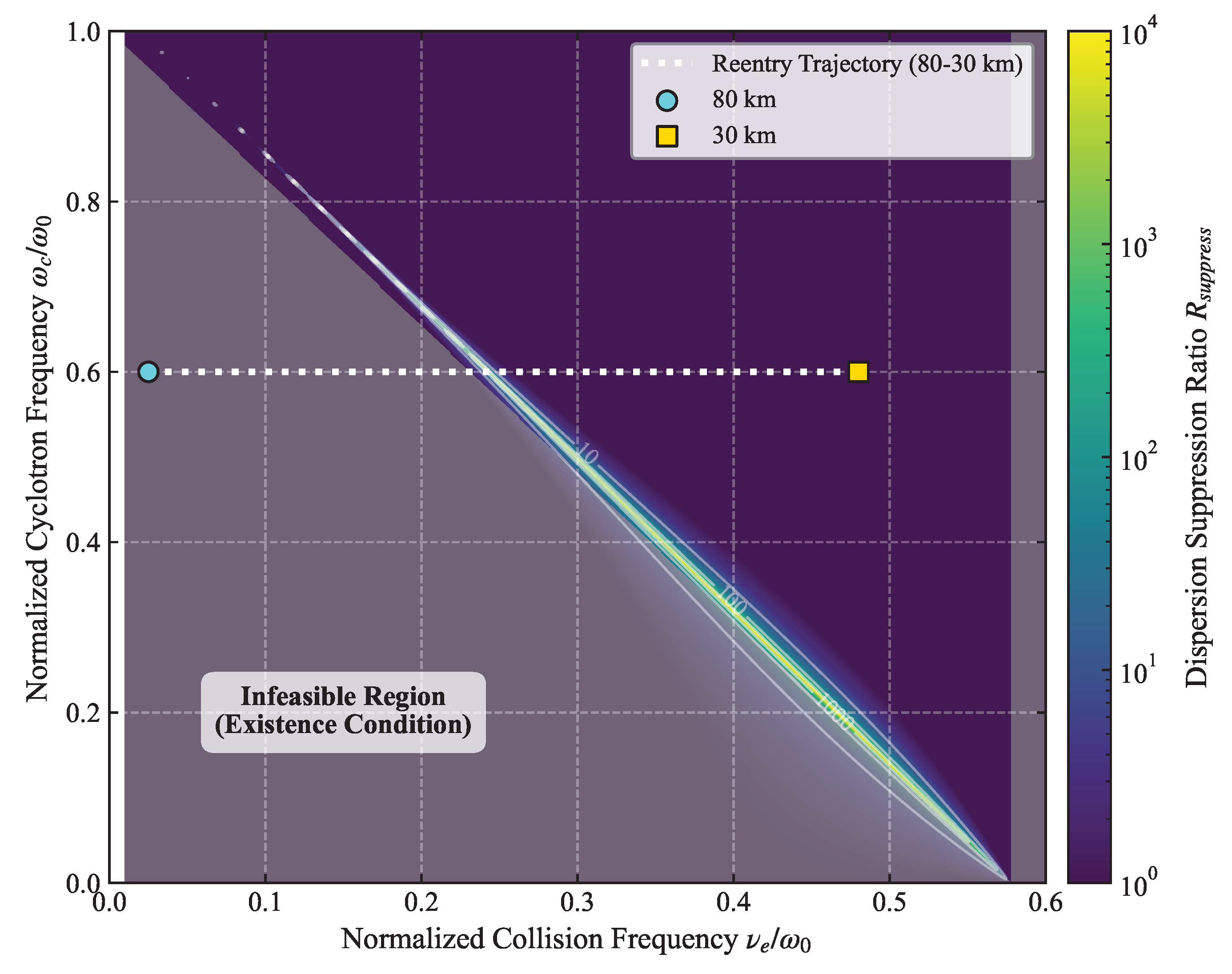
To systematically evaluate the parameter dependence of the dispersion immunity mechanism, Figure 3 presents the distribution of the suppression ratio in a two-dimensional parameter space spanned by the normalized collision frequency and the normalized cyclotron frequency .
It is observed that, within the physically realizable region, a narrow diagonal band of high suppression emerges, where the suppression ratio can reach values on the order of or higher. This high-suppression ridge corresponds precisely to the theoretical matching condition . In addition, the lower-left region of the map is physically inaccessible due to existence constraints, which is consistent with the theoretical analysis.
As shown in the figure, the diagonal distribution reveals a fundamental physical insight: dispersion suppression is not governed by a single parameter, such as collision frequency or magnetization strength, but instead relies critically on the dynamic balance between the two. Only when the collisional effect of the plasma and the externally imposed magnetization satisfy a strict matching condition can optimal suppression of group velocity dispersion be achieved.
To assess the applicability of this mechanism in realistic reentry environments, a representative trajectory from 80 km to 30 km altitude is superimposed in Figure 3 (white horizontal dashed line). The collision frequency is assumed to increase linearly with altitude decreasing [25]. A constant external magnetic field is assumed, corresponding to a fixed normalized cyclotron frequency of . It can be observed that, during the initial stage of reentry, the operating point lies close to the high-suppression region. However, as the altitude decreases, the collision frequency increases rapidly, causing the operating point to deviate from the optimal matching condition, and the suppression performance deteriorates accordingly.
This result indicates that, in dynamically evolving reentry environments, static parameter matching alone is insufficient to maintain optimal performance. Instead, adaptive control strategies must be introduced.
This inherent physical limitation fundamentally motivates the incorporation of a dynamic compensation mechanism, whereby the external magnetic field is adaptively tuned in response to real-time variations in the plasma collision frequency. As illustrated in the figure, if the magnetic field is adjusted to ensure that the operating trajectory remains locked within the high-suppression band, the magnetically induced transparency effect can be effectively activated, thereby fundamentally mitigating waveform distortion caused by plasma turbulence and dispersion.
5. Discussion
The preceding results demonstrate that the effectiveness of the proposed suppression mechanism critically depends on a specific parameter-matching condition, which exhibits pronounced temporal variability in realistic reentry environments. As the vehicle descends, plasma parameters continuously evolve; in particular, the collision frequency typically increases rapidly with atmospheric density, causing the system operating point to drift in the parameter space. Under such circumstances, conventional static magnetic field configurations are unable to maintain optimal matching throughout the entire reentry process. Consequently, the system inevitably deviates from the high-suppression region, leading to the re-emergence of propagation distortion. Therefore, to fully exploit the advantages of the proposed mechanism in practical applications, the incorporation of dynamic control strategies is essential. For instance, by adjusting the external magnetic field strength or adaptively tuning the operating frequency, the system operating point can be steered to evolve along the optimal suppression ridge. Furthermore, a closed-loop control framework can be established by integrating real-time plasma parameter estimation, enabling sustained near-optimal propagation performance in strongly dynamic environments.
From a methodological perspective, the proposed mechanism differs fundamentally from conventional approaches that rely on receiver-side signal processing. Instead, it constitutes a physical-layer regulation strategy that directly targets the propagation process itself. The core idea is to modify the coupling between the electromagnetic wave and the plasma medium, thereby suppressing dispersion effects during propagation rather than compensating for them a posteriori at the receiver. This “forward-control” paradigm avoids reliance on complex post-processing algorithms and offers potential advantages in highly dynamic environments dominated by strong irregularities, particularly in extreme communication scenarios such as reentry blackout.
It should be noted that the present analysis is based on a certain level of idealized modeling and does not fully account for complex factors such as strong turbulence intermittency, multi-scale irregular structures, and three-dimensional spatial inhomogeneity. These effects may influence the robustness and applicability of the suppression mechanism. Therefore, future work should incorporate higher-fidelity plasma models, as well as experimental and numerical validation, to systematically assess the performance limits of the proposed approach in realistic reentry environments.
6. Conclusion
In this paper, the dispersion immunity mechanism for electromagnetic wave propagation in magnetized plasma has been systematically investigated. By establishing a dispersion model incorporating collisional effects and introducing a sensitivity analysis framework, the condition under which group velocity dispersion becomes immune to plasma density fluctuations has been derived.
Theoretical analysis reveals that when the detuning parameter satisfies , the sensitivity of group velocity dispersion vanishes, thereby enabling effective suppression of turbulence-induced pulse broadening. Numerical simulations corroborate this result and demonstrate that, under optimal matching conditions, pulse broadening can be significantly reduced, with suppression ratios reaching several orders of magnitude. Further analysis in the parameter space uncovers the existence of a high-suppression ridge and indicates that the proposed mechanism relies on a precise balance between collisional and magnetization effects. Reentry trajectory analysis further shows that, in dynamically evolving environments, adaptive control strategies are required to maintain optimal performance.
The findings of this work provide a novel physical mechanism and design paradigm for addressing the plasma-induced communication blackout problem during reentry, offering valuable insights for the development of robust wireless communication systems in extreme environments.
Funding
This work was supported in part by the National Natural Science Foundation of China (No. 41727804, U25A20784 and U24A20603); and in part by the Natural Science Foundation of Jiangxi (Grant No. 20224BAB212027 and 20242BAB25055), and in part by the Financial Contract of the Science and Technology Project of Jiangxi Province (No. ZBG20230418032).
Acknowledgments
We thank all reviewers for their constructive comments.
Conflicts of Interest
The authors declare no conflicts of interest.
References
- Rybak, J.P.; Churchill, R. Progress in Reentry Communications. IEEE Trans. Aerosp. Electron. Syst. 1971, AES-7, 879–894. [Google Scholar] [CrossRef]
- Shi, L.; Guo, B.; Liu, Y.; Li, J. Characteristic of plasma sheath channel and its effect on communication. Prog. Electromagn. Res. 2012, 123. [Google Scholar] [CrossRef]
- Takahashi, Y.; Yamada, K.; Abe, T. Prediction Performance of Blackout and Plasma Attenuation in Atmospheric Reentry Demonstrator Mission. J. Spacecr. Rocket. 2014, 51, 1954–1964. [Google Scholar] [CrossRef]
- Starkey, R.P. Hypersonic Vehicle Telemetry Blackout Analysis. J. Spacecr. Rocket. 2015, 52, 426–438. [Google Scholar] [CrossRef]
- He, G.; Zhan, Y.; Zhang, J.; Ge, N. Characterization of the Dynamic Effects of the Reentry Plasma Sheath on Electromagnetic Wave Propagation. IEEE Trans. PLASMA Sci. 2016, 44, 232–238. [Google Scholar] [CrossRef]
- Liu, Y.; Wei, H.; Shi, L.; Yao, B. Adaptive protograph-based BICM-ID relying on the RJ-MCMC algorithm: a reliable and efficient transmission solution for plasma sheath channels. PLASMA Sci. Technol. 2022, 24. [Google Scholar] [CrossRef]
- Keidar, M.; Kim, M.; Boyd, I.D. Electromagnetic reduction of plasma density during atmospheric reentry and hypersonic flights. J. Spacecr. Rocket. 2008, 45, 445–453. [Google Scholar] [CrossRef]
- Gillman, E.D.; Foster, J.E.; Blankson, I.M. Technical Report NASA/TM-2010-216211 NASA NTRS ID: 20100008938; Review of Leading Approaches for Mitigating Hypersonic Vehicle Communications Blackout and a Method of Ceramic Particulate Injection Via Cathode Spot Arcs for Blackout Mitigation. National Aeronautics and Space Administration (NASA), 2010.
- Zheng, L.; Zhao, Q.; Liu, S.; Xing, X.; Chen, Y. Theoretical and Experimental Studies of Terahertz Wave Propagation in Unmagnetized Plasma. J. INFRARED Millim. TERAHERTZ WAVES 2014, 35, 187–197. [Google Scholar] [CrossRef]
- Zhang, J.; Han, B.; Zhao, S.; Zhang, G.; Duan, W. A study of the transmission characteristics of terahertz waves in hypersonic target flow field. J. PLASMA Phys. 2022, 88. [Google Scholar] [CrossRef]
- Rodriguez Fuentes, F.M.; Parent, B. Electron density depletion in reentry plasma flows using pulsed electric fields. Phys. FLUIDS 2026, 38. [Google Scholar] [CrossRef]
- Kim, M.; Keidar, M.; Boyd, I.D. Analysis of an Electromagnetic Mitigation Scheme for Reentry Telemetry Through Plasma. J. Spacecr. Rocket. 2008, 45, 1223–1229. [Google Scholar] [CrossRef]
- Zuppardi, G.; Savino, R.; Mongelluzzo, G. Aero-thermo-dynamic analysis of a low ballistic coefficient deployable capsule in Earth re-entry. Acta Astronaut. 2016, 127, 593–602. [Google Scholar] [CrossRef]
- Thoma, C.; Rose, D.V.; Miller, C.L.; Clark, R.E.; Hughes, T.P. Electromagnetic wave propagation through an overdense magnetized collisional plasma layer. J. Appl. Phys. 2009, 106. [Google Scholar] [CrossRef]
- Mehra, N.; Singh, R.; Bera, S. Mitigation of communication blackout during re-entry using static magnetic field. Prog. Electromagn. Res. B 2015, 63, 161–172. [Google Scholar] [CrossRef]
- Zhou, H.; Li, X.; Liu, Y.; Bai, B.; Xie, K. Effects of Nonuniform Magnetic Fields on the “Magnetic Window” in Blackout Mitigation. IEEE Trans. PLASMA Sci. 2017, 45, 15–23. [Google Scholar] [CrossRef]
- Zhou, H.; Li, X.; Xie, K.; Liu, Y.; Yao, B.; Ai, W. Characteristics of electromagnetic wave propagation in time-varying magnetized plasma in magnetic window region of reentry blackout mitigation. AIP Adv. 2017, 7. [Google Scholar] [CrossRef]
- Koehn, A.; Holzhauer, E.; Leddy, J.; Thomas, M.B.; Vann, R.G.L. Influence of plasma turbulence on microwave propagation. PLASMA Phys. Control. FUSION 2016, 58. [Google Scholar] [CrossRef]
- Gao, Y.; Yang, M.; Xie, K.; Qiao, L.; Liu, H.; Li, C.; Liu, D.; Quan, L.; Wu, M.; Li, X. Parasitic modulation effect caused by dynamic plasma in low frequency. Phys. PLASMAS 2024, 31. [Google Scholar] [CrossRef]
- Shi, L.; Yao, B.; Zhao, L.; Liu, Y.; Li, X. Electromagnetic coupling effect in the complex integrated channel of hypersonic vehicles and experimental verification. Phys. PLASMAS 2019, 26. [Google Scholar] [CrossRef]
- Yao, B.; Li, X.; Shi, L.; Liu, Y.; Zhu, C. A Multiscale Model of Reentry Plasma Sheath and Its Nonstationary Effects on Electromagnetic Wave Propagation. IEEE Trans. PLASMA Sci. 2017, 45, 2227–2234. [Google Scholar] [CrossRef]
- Yao, B.; Li, X.; Shi, L.; Liu, Y.; Zhu, C. A Geometric-Stochastic Integrated Channel Model for Hypersonic Vehicle: A Physical Perspective. IEEE Trans. Veh. Technol. 2019, 68, 4328–4341. [Google Scholar] [CrossRef]
- Liu, J.F.; Ma, H.Y.; Jiao, Z.H.; Bai, G.H.; Fang, Y.; Yi, Y.M.; Xi, X. Effects of Dynamic Plasma Sheath on Electromagnetic Wave Propagation and Bit Error Rate Under External Magnetic Field. IEEE Trans. PLASMA Sci. 2020, 48, 2706–2714. [Google Scholar] [CrossRef]
- Deng, Q.; Chen, W.; Ma, Q.; Yang, L. Analysis of Electromagnetic Wave Propagation Characteristics Based on Plasma Turbulence. In Proceedings of the 2022 IEEE 5th International Conference on Electronic Information and Communication Technology (ICEICT), 2022; pp. 271–273. [Google Scholar] [CrossRef]
- Sun, H.; Wang, J.; Han, Y.; Cui, Z.; Sun, P.; Shi, X.; Zhao, W. Backward Scattering Characteristics of a Reentry Vehicle Enveloped by a Hypersonic Flow Field. Int. J. Antennas Propag. 2018, 2018, 5478580. Available online: https://onlinelibrary.wiley.com/doi/pdf/10.1155/2018/5478580. [CrossRef]
Figure 1.
Normalized group velocity dispersion (GVD) sensitivity as a function of the normalized detuning parameter for right-hand circularly polarized (RCP) and left-hand circularly polarized (LCP) waves. The zero-crossing points at indicate the dispersion immunity condition, where the first-order sensitivity to plasma density fluctuations vanishes.
Figure 1.
Normalized group velocity dispersion (GVD) sensitivity as a function of the normalized detuning parameter for right-hand circularly polarized (RCP) and left-hand circularly polarized (LCP) waves. The zero-crossing points at indicate the dispersion immunity condition, where the first-order sensitivity to plasma density fluctuations vanishes.
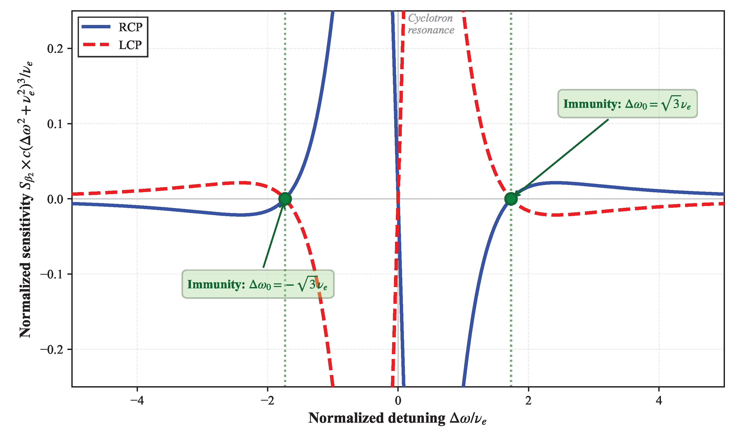
Figure 2.
Demonstration of dispersion suppression in pulse propagation through magnetized plasma. (a) Temporal waveforms after propagation, showing severe pulse broadening in the unmatched case (red) and near-distortionless transmission under the dispersion immunity condition (blue), compared with the initial pulse (black). (b) Corresponding evolution of the broadening factor versus propagation distance. The unmatched case exhibits rapid growth due to strong group velocity dispersion, while the immunity condition maintains , confirming that dispersive (and turbulence-induced) pulse distortion can be fundamentally suppressed through parameter matching.
Figure 2.
Demonstration of dispersion suppression in pulse propagation through magnetized plasma. (a) Temporal waveforms after propagation, showing severe pulse broadening in the unmatched case (red) and near-distortionless transmission under the dispersion immunity condition (blue), compared with the initial pulse (black). (b) Corresponding evolution of the broadening factor versus propagation distance. The unmatched case exhibits rapid growth due to strong group velocity dispersion, while the immunity condition maintains , confirming that dispersive (and turbulence-induced) pulse distortion can be fundamentally suppressed through parameter matching.
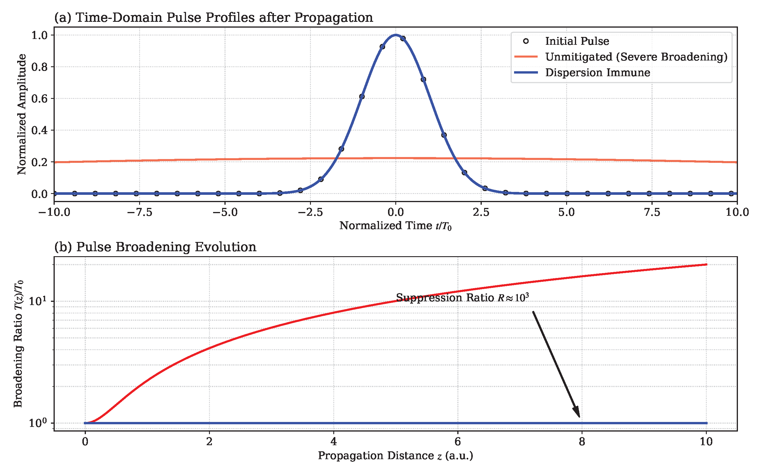
Figure 3.
Dispersion suppression map in the parameter space. A narrow diagonal ridge of high suppression () emerges, consistent with the theoretical matching condition , indicating that optimal dispersion suppression arises from a precise balance between collisional damping and magnetization. The infeasible region is excluded by existence constraints. The superimposed reentry trajectory (80–30 km) demonstrates that fixed magnetic field conditions lead to deviation from the optimal regime as collision frequency increases, motivating adaptive control strategies.
Figure 3.
Dispersion suppression map in the parameter space. A narrow diagonal ridge of high suppression () emerges, consistent with the theoretical matching condition , indicating that optimal dispersion suppression arises from a precise balance between collisional damping and magnetization. The infeasible region is excluded by existence constraints. The superimposed reentry trajectory (80–30 km) demonstrates that fixed magnetic field conditions lead to deviation from the optimal regime as collision frequency increases, motivating adaptive control strategies.
Disclaimer/Publisher’s Note: The statements, opinions and data contained in all publications are solely those of the individual author(s) and contributor(s) and not of MDPI and/or the editor(s). MDPI and/or the editor(s) disclaim responsibility for any injury to people or property resulting from any ideas, methods, instructions or products referred to in the content. |
© 2026 by the authors. Licensee MDPI, Basel, Switzerland. This article is an open access article distributed under the terms and conditions of the Creative Commons Attribution (CC BY) license.
Copyright: This open access article is published under a Creative Commons CC BY 4.0 license, which permit the free download, distribution, and reuse, provided that the author and preprint are cited in any reuse.


