

Submitted:
04 May 2026
Posted:
06 May 2026
You are already at the latest version
Abstract
Miniaturization of photonic integrated circuits is a long-standing problem in optical engineering. Nowadays, the most promising material platform for integrated photonics are anisotropic van der Waals materials due to overcoming the light diffraction limit. Here, we numerically study v-groove channel waveguides formed in a 50-nm-thick slab of the in-plane hyperbolic in visible and near-infrared ranges van der Waals material MoOCl₂. At the telecom wavelength 1550 nm, a channel supports a guided mode with an effective index 1.0206 and a decay length of 13.7 µm. We also design a Mach–Zehnder–type interferometric layout with a maximum splitter angle of approximately 7° for demonstration of a possible practical application in a telecom range and in-plane angular channel modes propagation characteristics. We demonstrate that using MoOCl2 instead of gold leads to a tenfold reduction in the linear dimensions of the photonic integrated circuit. Therefore, we envision that by combining the extraordinary material properties of MoOCl2 with the v-shaped geometry of waveguides, one can make the integration density of photonic devices close to electronics.
Keywords:
photonic integrated circuits
; v-groove optical waveguides
; channel polaritons
; telecommunication
; van der Waals material MoOCl₂
; in-plane anisotropy in the visible range
; hyperbolic plasmon polaritons
; Mach–Zehnder interferometer
1. Introduction
One of the main challenges in modern optical engineering is the spatial scaling of photonic integrated circuit elements to sizes comparable to the characteristic base sizes of nanoelectronic components. A fundamental obstacle to the ultra-dense integration of all-optical devices is the diffraction limit, which sets the minimum size of the electromagnetic field localization region in traditional dielectric guide structures. The classical approach to overcoming the diffraction limit in visible and near-infrared ranges is based on the use of surface plasmon polaritons [1,2,3,4,5] excited at the interface between a dielectric and a noble metal. However, the use of isotropic plasmonic platforms still does not provide the required dimensions for an integrating circuit.
Highly anisotropic layered van der Waals crystals [6,7], which provide compatibility with planar technology, are currently being intensively studied as an alternative material base. The presence of hyperbolic in-plane dispersion of permittivity in such media allows the existence of electromagnetic eigenmodes [8] with large wave vectors—hyperbolic polaritons, characterized by deep subwavelength spatial confinement of the field. However, the practical application of most of the studied hyperbolic media, such as hBN [9] or α-MoO3 [10,11], is spectrally limited to the mid-infrared range due to the phonon nature of their resonances. In this regard, MoOCl2 [12,13,14,15,16,17,18,19,20,21,22], which is capable of supporting hyperbolic plasmonic polaritons in the technologically in-demand visible and near-infrared parts of the spectrum, has attracted particular attention.
Despite the intense study of the fundamental electrodynamic properties of MoOCl2, the problem of efficient signal propagation in waveguiding structures [23] based on this material requires separate consideration. The influence of the transverse geometry of the waveguide on the dispersion and transport characteristics of guided modes in hyperbolic media remains insufficiently studied. The formation of traditional strip waveguides from layered crystals using nanolithography and reactive ion etching is accompanied by material degradation at the structure boundaries, which can lead to signal scattering.
In this context, the use of channel-type guiding structures—waveguides with a v-shaped cross-sectional profile—seems to be an electrodynamically and technologically viable solution. As in classical studies [24,25] examining channel plasmon modes in metals, the v-shaped geometry facilitates localization of the electromagnetic field within the channel, minimizing the influence of edge surface defects on the attenuation of plasmon-polaritons in MoOCl2.
In this paper, we numerically study the guiding properties of v-shaped optical subwavelength channel waveguides based on the hyperbolic material MoOCl2 and propose a computational model for a subwavelength Mach-Zehnder interferometer based on coupled channel waveguides.
2. Materials and Methods
In this work, we start with simulation of a v-shaped straight groove of width w and depth t, formed in a MoOCl₂ layer with a thickness of d = 50 nm and oriented along the [100] crystallographic axis. We consider the wavelength range of 360–1700 nm, where the dielectric permittivity tensor has a negative component along the [100] axis and positive components along the [010] and [001] axes, giving rise to a hyperbolic in-plane dispersion law.
Numerical calculations were prepared in COMSOL Multiphysics. MoOCl₂ was modeled as a biaxial dispersive medium with a diagonal dielectric tensor [15] in the crystallographic basis [100], [010], and [001]. The tensor orientation was changed throughout the simulations by in-plane rotation matrixes, while the propagation direction of the v-groove channel was kept fixed in order to find its eigenmodes.
3. Results
The groove plays a dual role: it reduces the characteristic transverse size of the mode and defines its direction of propagation within the plane of the structure. The field distribution in the cross-section (Figure 1a) demonstrates significant localization of the mode near the groove.
on the wavelength for a layer of thickness = 50 nm (black solid line for full-wave simulations, blue dashed line for analytical calculations) and for channel mode (green stars, waveguide dimensions are d = 50 nm, w = 30 nm and t = 30 nm). Right-hand scale: dependency of the decay length in a layer of thickness = 50 nm on the wavelength of incident light (solid red line).
The real part of the normalized wave number and the decay length were considered as the main characteristics of the mode, parameters are given by:
From the dependency of an effective mode index on wavelength (Figure 1b), we see that this value is approximately identical for the fundamental mode of the layer [8] and for the channel mode within it, yielding values slightly greater than 1, indicating the subwavelength nature of the channel mode. Furthermore, calculation of the channel mode decay length for the telecommunication range of 1260–1625 nm shows that these waves propagate over distances of 8 – 15.5 μm, which are sufficient for engineering applications.
However, to develop functional elements of optical circuits, such as splitters, elliptical resonators and interference elements, it is necessary to form waveguides at arbitrary in-plane angles to the optical axes of the crystal. By the wavelength = 1550 nm, we studied the dependence of the channel mode effective index on the angle between the [100] axis of the crystal and the waveguide axis (Figure 2a). Having plotted an isofrequency curve for the same wavelength = 1550 nm (Figure 2b), we found that the maximum channel mode propagation angle is 10°. It should be noted that channel modes also exhibit stronger light localization with increasing of angle α than the fundamental mode in the layer.
on the angle α between [100] axis of MoOCl2 and channel axis. (b) Isofrequency curve for the channel mode (red stars and interpolated dash line) and the fundamental slab mode (full-wave calculations, black points and interpolated dash line). Schematic image for channel in-plane direction (grey dashed line) defined by α in the inset. Wavelength λ = 1550 nm, parameters of the structure d = 50 nm, w = 30 nm and t = 30 nm for both (a) and (b).
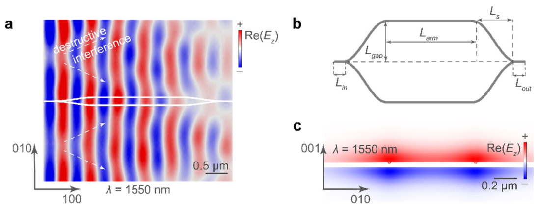
To demonstrate its practical applicability, we simulated a model of a waveguide and a Mach-Zehnder interferometer based on it, performing a full-wave calculation at a wavelength of = 1550 nm. It was performed via numerical simulations to find the eigenmodes of the waveguide and calculate the normal component of the electric field Re() (Figure 3a, c) of waves propagating in the interferometer to visualize the interference pattern.
Efficient signal propogation along the interferometer requires adiabatic changes in the curvature of its arms, for which they are given an S-shape, defined by the function:
where , are the coordinates along the [100] and [010] axes. In addition, due to in-plane hyperbolicity, it is necessary that the maximum angle formed by the tangent to the function and the -axis does not exceed 10°. At this angle, the channel mode remains guided in the waveguide at a wavelength of = 1550 nm. Finding the derivative of this function and its maximum value, we see that the selected parameters (Lin = 500 nm, Lgap = 200 nm, Larm = 2 μm, Ls = 2.5 μm, Lout = 500 nm) (Figure 3b) give the permissible value of the angle:
The waveguide parameters w = 30 nm and t = 30 nm were chosen by varying them (Table 1A in the Appendix A section) in order to minimize the channel width and maximize the effective mode index q and its path length Ldec. To achieve the interference effect, Ldec must be guaranteed to exceed the interferometer arm length Ltotal = Lin + Ls + Larm + Ls + Lout. In addition, the condition for the transfer coefficient << 1 is satisfied everywhere on the bends.
4. Discussion
The comparative analysis (Table 1) demonstrates that the proposed MoOCl2 platform instead of gold one enables to reduce (10-fold in in-plane dimensions, 25-fold in out-of-plane dimensions) the linear dimensions of the base elements while maintaining the efficiency of subwavelength signal propagation in the telecommunications range. To demonstrate the functional potential of the developed architecture, a computational model of a Mach-Zehnder interferometer based on coupled channel waveguides is proposed.
5. Conclusions
In conclusion, the obtained results demonstrate that the combination of the optical anisotropy of MoOCl2 and the v-shaped geometry leads to significant approach of the photonic devices sizes to the standards of modern semiconductor electronics. More broadly, given recent advances in the fabrication [26,27,28] and nanostructure processing [29,30,31] of van der Waals materials, we anticipate that our findings will be used in next-generation integrated circuits, where van der Waals materials will complement traditional material platforms such as silicon [32,33,34,35].

Table 1.
Comparison of the liner geometrical parameters and propagation wavelength with other works (n = 1.02, λ = 1550 nm, v-shaped waveguide).
Table 1.
Comparison of the liner geometrical parameters and propagation wavelength with other works (n = 1.02, λ = 1550 nm, v-shaped waveguide).
| Criterion |
Bozhevolnyi, S. I. et al. [24] Isotropic Model (Au) |
This Work Anisotropic Model (MoOCl2) |
|
w and t, nm Ldec, μm |
277/1250 30 |
30/50 13.7 |
Author Contributions
A.A., V.V. and A.V. suggested and directed the project. O.M., K.V., M.T. and S.C. provided theoretical support. O.M. wrote the original manuscript with input of A.A. and A.V. All authors have read and agreed to the published version of the manuscript.
Funding
O.M. acknowledge the support from the Russian Science Foundation (grant №24-79-00308).
Data Availability Statement
The datasets generated during and/or analyzed during the current
study are available from the corresponding author on reasonable request.
Conflicts of Interest
The authors declare no conflicts of interest.
Appendix A
It was found that for the geometric parameters listed in Table A1, the effective mode index q for λ = 1550 nm remains equal to 1.0206, indicating the weak sensitivity to the considered cross-sectional variations. For the interferometer simulation, we chose parameters w = 30 nm and t = 30 nm.
Table A1.
The influence of the geometric parameters of the v-channel on the effective mode index q and the decay length Ldec for λ = 1550 nm during propagation along the [100] axis.
Table A1.
The influence of the geometric parameters of the v-channel on the effective mode index q and the decay length Ldec for λ = 1550 nm during propagation along the [100] axis.
| w and t, nm | Re(q) | Im(q) | Ldec, μm | |
| 60/30 | 1.0206 | 0.01807 | 13.650 | |
| 60/45 | 1.0206 | 0.01809 | 13.635 | |
| 120/45 | 1.0206 | 0.01818 | 13.569 | |
| 30/30 | 1.0206 | 0.01806 | 13.662 | |
| 120/30 | 1.0206 | 0.01811 | 13.621 |
In contrast to the telecom range, in the visible range we observe large losses and, as a consequence, short signal decay lengths. (Table A2).
Table A2.
The influence of the geometric parameters of the v-channel on the effective mode index q and the decay length Ldec for λ = 600 nm during propagation along the [100] axis.
Table A2.
The influence of the geometric parameters of the v-channel on the effective mode index q and the decay length Ldec for λ = 600 nm during propagation along the [100] axis.
| w and t, nm | Re(q) | Ldec, nm |
| 60/30 | 1.3948 | 1109 |
| 60/45 | 1.4043 | 1086 |
| 120/45 | 1.4434 | 1022 |
| 120/30 | 1.4112 | 1071 |
References
- Raether, H. Surface Plasmons. In Springer-Verlag; 1988. [Google Scholar]
- Novikov, I.V.; Maradudin, A.A. Channel polaritons. Phys. Rev. B 2002, 66, 035403. [Google Scholar] [CrossRef]
- Barnes, W.L.; Dereux, A.; Ebbesen, T.W. Surface plasmon subwavelength optics. Nature 2003, 424, 824. [Google Scholar] [CrossRef]
- Pile, D.F.P.; Gramotnev, D.K. Channel plasmon–polariton in a triangular groove on a metal surface. Opt. Lett. 2004, 29, 1069. [Google Scholar] [CrossRef]
- Gramotnev, D.K.; Bozhevolnyi, S.I. Plasmonics beyond the diffraction limit. Nat. Photonics 2010, 4, 83–91. [Google Scholar] [CrossRef]
- Basov, D.N.; Fogler, M.M.; de Abajo, F.J.G. Polaritons in van der Waals materials. Science 2016, 354, aag1992. [Google Scholar] [CrossRef]
- Low, T.; et al. Polaritons in layered two-dimensional materials. Nat. Mat. 2017, 16, 182–194. [Google Scholar] [CrossRef] [PubMed]
- Álvarez-Pérez, G.; Voronin, K.V.; Volkov, V.S.; Alonso-González, P.; Nikitin, A.Y. Analytical approximations for the dispersion of electromagnetic modes in slabs of biaxial crystals. Phys. Rev. B 2019, 100, 11. [Google Scholar] [CrossRef]
- Segura, A.; Artús, L.; Cuscó, R.; Taniguchi, T.; Cassabois, G.; Gil, B. Natural optical anisotropy of h-BN: highest giant birefringence in a bulk crystal through the mid-infrared to ultraviolet range. Phys. Rev. Mat. 2018, 2, 024001. [Google Scholar] [CrossRef]
- Ma, W.; et al. In-plane anisotropic and ultra-low-loss polaritons in a natural van der Waals crystal. Nature 2018, 562, 557–562. [Google Scholar] [CrossRef] [PubMed]
- Zheng, Z. B.; et al. A mid-infrared biaxial hyperbolic van der Waals crystal. Sci. Adv. 2019, 5, eaav8690. [Google Scholar] [CrossRef]
- Wang, Z.; et al. Fermi liquid behavior and colossal magnetoresistance in layered MoOCl2. Phys. Rev. Mat. 2020, 4, 041001(R). [Google Scholar] [CrossRef]
- Venturi, G.; Mancini, A.; Melchioni, N.; Chiodini, S.; Ambrosio, A. Visible-frequency hyperbolic plasmon polaritons in a natural van der Waals crystal. Nat. Commun. 2024, 15, 9727. [Google Scholar] [CrossRef]
- Ruta, F. L.; et al. Good plasmons in a bad metal. Science 2025, 387, 786791. [Google Scholar] [CrossRef]
- Ermolaev, G.; et al. Giant optical anisotropy and visible-frequency epsilon-near-zero in hyperbolic van der Waals MoOCl2. Nano Lett. 2026, 26, 13. [Google Scholar] [CrossRef]
- Minnekhanov, A. Hyperbolic-enhanced Raman scattering in van der Waals MoOCl2: from Fano resonances to picomolar detection. arXiv arXiv:2512.17647.
- Tong, H. MoOCl2 as a hyperbolic planar platform for nanooptics at telecom frequencies. arXiv arXiv:2602.09186.
- Melchioni, N.; Mancini, A.; Nan, L.; Efimova, A.; Venturi, G.; Ambrosio, A. Giant optical anisotropy in a natural van der Waals hyperbolic crystal for visible light low-loss polarization control. ASC Nano 2025, 19, 27. [Google Scholar] [CrossRef] [PubMed]
- Ermolaev, G. Deep-subwavelength and broadband quarter-wave retardation in ultrathin hyperbolic MoOCl2. arXiv arXiv:2604.05236.
- Li, Y.; et al. Broadband near-infrared hyperbolic polaritons in MoOCl₂. Nat. Commun. 2025, 16, 6172. [Google Scholar] [CrossRef]
- Melchioni, N.; Mancini, A.; Ambrosio, A. Anisotropic electron gas in a hyperbolic van der Waals material. arXiv arXiv:2602.01072. [CrossRef]
- Clemente-Marcuello, C. Launching of visible-range hyperbolic polaritons by gold nanoantennas in a natural van der Waals crystal. arXiv arXiv:2602.09180. [CrossRef]
- Matveeva, O. G.; Voronin, K. V.; Grudinin, D. V.; Chikalkin, S. D.; Pak, N. V.; Titova, M. I.; Baranov, D. G.; Vyshnevyy, A. A.; Volkov, V. S.; Arsenin, A. V. Mode composition of waveguides based on a van der Waals crystal hyperbolic within the visible range. Tech. Phys. Lett. 2026, 2, 64. [Google Scholar]
- Bozhevolnyi, S.I.; Volkov, V.S.; Devaux, E.; Ebbesen, T.W. Channel plasmon-polariton guiding by subwavelength metal grooves. Phys. Rev. Lett. 2005, 95, 046802. [Google Scholar] [CrossRef] [PubMed]
- Bozhevolnyi, S.I.; Volkov, V.S.; Devaux, E.; Laluet, J.-Y.; Ebbesen, T.W. Channel plasmon subwavelength waveguide components including interferometers and ring resonators. Nature 2006, 440, 508. [Google Scholar] [CrossRef] [PubMed]
- Liu, K.-K.; Zhang, W.; Lee, Y.-H.; Lin, Y.-C.; Chang, M.-T.; Su, C.-Y.; Chang, C.-S.; Li, H.; Shi, Y.; Zhang, H.; et al. Growth of large-area and highly crystalline MoS2 thin layers on insulating substrates. Nano Lett. 2012, 12, 1538. [Google Scholar] [CrossRef]
- Najmaei, S.; Liu, Z.; Zhou, W.; Zou, X.; Shi, G.; Lei, S.; Yakobson, B.I.; Idrobo, J.C.; Ajayan, P.M.; Lou, J. Vapour phase growth and grain boundary structure of molybdenum disulphide atomic layers. Nat. Mater. 2013, 12, 754. [Google Scholar] [CrossRef]
- Dumcenco, D.; Ovchinnikov, D.; Marinov, K.; Lazi´c, P.; Gibertini, M.; Marzari, N.; Sanchez, O.L.; Kung, Y.-C.; Krasnozhon, D.; Chen, M.-W.; et al. Large-area epitaxial monolayer MoS2. ACS Nano 2015, 9, 4611. [Google Scholar] [CrossRef]
- Tselikov, G.I.; Ermolaev, G.A.; Popov, A.A.; Tikhonowski, G.V.; Panova, D.A.; Taradin, A.S.; Vyshnevyy, A.A.; Syuy, A.V.; Klimentov, S.M.; Novikov, S.M.; et al. Transition metal dichalcogenide nanospheres for high-refractive-index nanophotonics and biomedical theranostics. Proc. Natl. Acad. Sci. USA 2022, 119, e2208830119. [Google Scholar] [CrossRef]
- Munkhbat, B.; Yankovich, A.; Baranov, D.; Verre, R.; Olsson, E.; Shegai, T.O. Transition metal dichalcogenide metamaterials with atomic precision. Nat. Commun. 2020, 11, 4604. [Google Scholar] [CrossRef]
- Munkhbat, B.; Küçüköz, B.; Baranov, D.G.; Antosiewicz, T.J.; Shegai, T.O. Nanostructured transition metal dichalcogenide multilayers for advanced nanophotonics. Laser Photonics Rev. 2022, 2200057. [Google Scholar] [CrossRef]
- Atabaki, A.H.; Moazeni, S.; Pavanello, F.; Gevorgyan, H.; Notaros, J.; Alloatti, L.; Wade, M.T.; Sun, C.; Kruger, S.A.; Meng, H.; et al. Integrating photonics with silicon nanoelectronics for the next generation of systems on a chip. Nature 2018, 556, 349. [Google Scholar] [CrossRef] [PubMed]
- Bogaerts, W.; Pérez, D.; Capmany, J.; Miller, D.A.B.; Poon, J.; Englund, D.; Morichetti, F.; Melloni, A. Programmable photonic circuits. Nature 2020, 586, 207. [Google Scholar] [CrossRef] [PubMed]
- Bogaerts, W.; Pérez, D.; Capmany, J.; Miller, D.A.B.; Poon, J.; Englund, D.; Morichetti, F.; Melloni, A. Programmable photonic circuits. Nature 2020, 586, 207. [Google Scholar] [CrossRef]
- Tanaka, Y. Recent progress in the development of large-capacity integrated silicon photonics transceivers. IEICE Trans. Electron. 2019, E102.C, 357. [Google Scholar] [CrossRef]
Figure 1.
Channel mode in v-shaped waveguide based on MoOCl2. (a) Atomic in-plane structure of MoOCl2 (molybdenum atoms are shown in blue, oxygen in red, and chlorine in yellow), linear-scale field distribution of out-of-plane component Re(Ez) in the channel mode and schematic image of the structure. (b) Left-hand scale: dependency of the effective index of the fundamental mode
Figure 1.
Channel mode in v-shaped waveguide based on MoOCl2. (a) Atomic in-plane structure of MoOCl2 (molybdenum atoms are shown in blue, oxygen in red, and chlorine in yellow), linear-scale field distribution of out-of-plane component Re(Ez) in the channel mode and schematic image of the structure. (b) Left-hand scale: dependency of the effective index of the fundamental mode
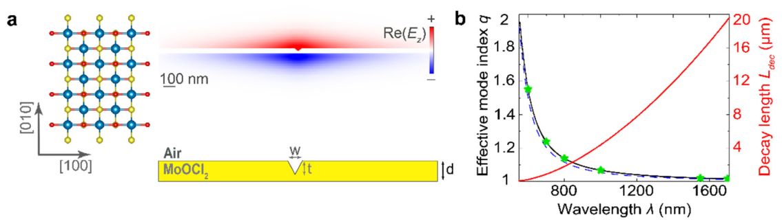
Figure 2.
Angular dependency of the channel mode effective index. (a) Dependency of the effective index of the channel mode
Figure 2.
Angular dependency of the channel mode effective index. (a) Dependency of the effective index of the channel mode
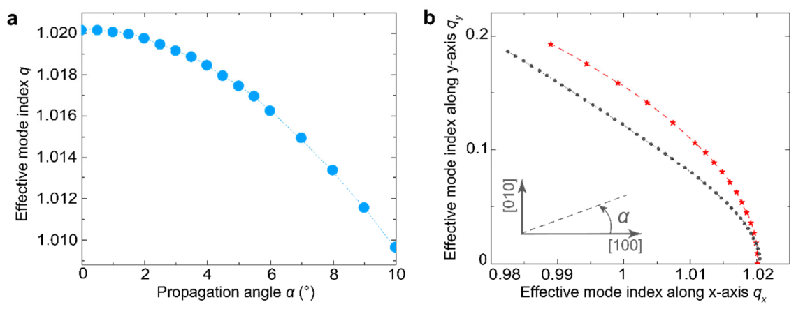
Figure 3.
Mach-Zender interferometer based on MoOCl2 slab. (a) Top-view and linear-scale field distribution of out-of-plane component Re(Ez). (b) Schematic image of interferometer (Lin = 500 nm, Lgap = 200 nm, Larm = 2 μm, Ls = 2.5 μm, Lout = 500 nm). (c) Linear-scale field distribution of out-of-plane component Re(Ez) in the middle part of interferometer. Wavelength λ = 1550 nm, parameters of the waveguide w = 30 nm and t = 30 nm, layer thickness d = 50 nm for both (a) and (c). .
Figure 3.
Mach-Zender interferometer based on MoOCl2 slab. (a) Top-view and linear-scale field distribution of out-of-plane component Re(Ez). (b) Schematic image of interferometer (Lin = 500 nm, Lgap = 200 nm, Larm = 2 μm, Ls = 2.5 μm, Lout = 500 nm). (c) Linear-scale field distribution of out-of-plane component Re(Ez) in the middle part of interferometer. Wavelength λ = 1550 nm, parameters of the waveguide w = 30 nm and t = 30 nm, layer thickness d = 50 nm for both (a) and (c). .
Disclaimer/Publisher’s Note: The statements, opinions and data contained in all publications are solely those of the individual author(s) and contributor(s) and not of MDPI and/or the editor(s). MDPI and/or the editor(s) disclaim responsibility for any injury to people or property resulting from any ideas, methods, instructions or products referred to in the content. |
© 2026 by the authors. Licensee MDPI, Basel, Switzerland. This article is an open access article distributed under the terms and conditions of the Creative Commons Attribution (CC BY) license.
Copyright: This open access article is published under a Creative Commons CC BY 4.0 license, which permit the free download, distribution, and reuse, provided that the author and preprint are cited in any reuse.


