

Submitted:
29 April 2026
Posted:
30 April 2026
You are already at the latest version
Abstract
Ammonia (NH₃), as an indispensable chemical in modern agriculture and industry, has long been produced on a large scale through the traditional Haber-Bosch process. However, this process is not only highly energy-intensive but also accompanied by substantial CO₂ emissions, necessitating the development of green alternatives. Meanwhile, nitrate (NO₃−) pollution in water bodies has become increasingly severe, posing significant threats to both ecosystems and human health. In this study, we successfully designed a bimetallic iron-cobalt organic framework (FeCo-MOF) catalyst and, for the first time, applied it to the electrocatalytic nitrate reduction reaction for ammonia synthesis. Experimental results demonstrate that at a working potential of −1.5 V (vs. SCE), the catalyst exhibits outstanding catalytic performance, achieving a current density of 52.17 mA/cm² and a remarkable NH₄⁺ Faradaic efficiency of 97.90%, significantly surpassing those of single-metal Fe-MOF and Co-MOF counterparts. Through spectroscopic characterization and electrochemical analysis, we elucidated the synergistic mechanism of the Fe-Co bimetallic active sites. The scientific significance of this work lies in its dual contributions: providing an efficient electrocatalytic strategy for nitrate pollution remediation while pioneering a low-carbon-emission approach to green ammonia synthesis, thereby holding substantial environmental and energy implications.
Keywords:
ammonia
; electrochemical reduction
; MOF
1. Introduction
Electrocatalytic nitrate reduction reaction (NO3RR) represents an emerging green ammonia synthesis technology, distinguished by its mild operating conditions (room temperature and atmospheric pressure), high energy efficiency (low theoretical overpotential), and modular reactor design. These advantages position NO3RR as the most promising alternative to conventional NH3 production methods [1,2,3]. Nevertheless, escalating nitrate contamination in global water systems, driven by rapid industrial and agricultural development, has exposed critical limitations in traditional biological denitrification approaches, including suboptimal treatment efficiency (< 80%), risks of secondary pollution (e.g., N2O emissions), and demanding operational conditions [3,4]. Such anthropogenic disturbances to the nitrogen cycle not only destabilize ecosystems but also endanger public health through water and food chain contamination. Within current nitrate remediation technologies, electrochemical NO3RR has gained prominence in environmental catalysis research owing to its adjustable reaction parameters (pH 6–8), absence of toxic byproducts, and compatibility with renewable energy integration [2,5].
From energy and chemical engineering perspectives, ammonia (NH₃) serves as a crucial hydrogen carrier (17.6 wt% hydrogen content) and occupies a pivotal position in future energy systems due to its high energy density (4.32 kWh/kg) and well-established storage/transportation infrastructure [2,6]. Simultaneously, as an indispensable feedstock for synthetic fertilizers (e.g., urea, ammonium salts), fine chemicals (e.g., nitriles, amines), and other nitrogen-rich compounds, NH₃ plays an irreplaceable role in global chemical supply chains [7,8] . This dual functionality enables NO₃RR technology to achieve synergistic unification of environmental remediation and resource conversion, demonstrating remarkable circular economy value through "waste-treats-waste" strategy [9,10,11]. Notably, the NO₃RR process involves complex multi-electron/proton coupled transfer (NO₃⁻ + 9H⁺ + 8e⁻ → NH₃ + 3H₂O) with multiple possible branching pathways that generate various competitive byproducts including N₂ (via denitrification), NO₂⁻ (incomplete reduction), NO (gaseous byproduct), and N₂O (potent greenhouse gas). These side reactions significantly compromise NH₃ selectivity and Faradaic efficiency [9,12]. Over the past two decades, breakthroughs in NO₃RR electrocatalysis have been achieved through advanced characterization techniques and computational methods. Research focus has evolved from noble metal catalysts (Pt, Pd) to non-precious metal systems (Fe, Co, Cu), with mechanistic understanding progressing from macroscopic kinetics to atomic-level active site engineering [2,13,14]. Current high-performance NO₃RR catalysts mainly fall into three categories: MOF-derived metal oxides, MOF-supported noble metals, and MOF-derived bimetallic catalysts, each exhibiting unique advantages in activity, selectivity, and stability [15,16,17,18].
This study designed and developed a novel iron-cobalt bimetallic organic framework (FeCo-MOF) electrocatalyst for highly efficient nitrate reduction reaction (NO3RR). Through a solvothermal method, we successfully constructed MOF materials with well-defined Fe-Co dual active sites and innovatively employed carbon paper as conductive substrate, which significantly enhanced the material’s electron transport capability.
Experimental results demonstrate that in a neutral electrolyte (pH ≈ 7) containing 0.1 M NO₃−, the catalyst exhibited outstanding electrocatalytic performance at −1.5 V (vs. RHE): achieving a current density of 52.17 mA/cm² with NH3 selectivity exceeding 90% and significantly improved Faradaic efficiency. Particularly noteworthy is that in NO₃−free control experiments, the current density decreased by 76.3%, confirming effective suppression of the hydrogen evolution reaction (HER) and demonstrating excellent selective catalytic capability. Furthermore, systematic stability tests revealed that after continuous operation for 36 hours at a constant potential of −1.45 V, the catalyst showed less than 5% current density decay. XRD and SEM characterizations confirmed the intact crystal structure and morphology, indicating remarkable electrochemical stability. This study provides new insights for developing efficient and stable electrocatalysts for nitrate reduction, with significant application prospects.
2. Materials and Methods
2.1. Reagents and Sample Preparation
The FeCo-MOF material was synthesized through a solvothermal method with precise stoichiometric control. In a typical procedure, Fe(NO₃)₂·9H₂O (1.55 g, 1 mmol) and Co(NO₃)₃·6H₂O (1.11 g, 1 mmol) were accurately weighed in a 1:1 molar ratio and mixed with terephthalic acid (0.21 g, 1 mmol) in 40 mL of N, N-dimethylformamide (DMF). The mixture was vigorously stirred while an appropriate amount of triethylamine (TEA) was added dropwise to modulate the reaction environment. After continuous stirring for 2 h to ensure homogeneity, the solution was transferred into a Teflon-lined autoclave and maintained at 120 °C for 4 h. Upon cooling to room temperature naturally, the resulting product was centrifuged and washed three times with DMF to remove unreacted precursors, followed by drying at 60 °C to obtain the final FeCo-MOF.
2.2. Materials Characterization
The synthesized materials were systematically characterized using multiple analytical techniques. X-ray diffraction (XRD) analysis was performed on a Bruker D8 Advance diffractometer with Cu Kα radiation (λ = 1.5406 Å) to determine the crystalline structure of the samples. Morphological features were examined using field-emission scanning electron microscopy (FE-SEM, Hitachi S-4800II), while optical properties were investigated by UV-Visible spectroscopy [2,4].
2.3. Electrochemical Measurements
All electrochemical measurements were conducted in a standard three-electrode system using a 50 mL electrolytic cell, with data acquisition performed by a CHI660e electrochemical workstation (Shanghai Chenhua). The cell was physically divided into anode and cathode compartments by a Nafion proton exchange membrane. The working electrode consisted of a hydrophobic carbon paper uniformly coated with catalyst ink, while a saturated calomel electrode (SCE) and platinum electrode served as the reference and counter electrodes, respectively. To ensure system homogeneity and temperature stability, the catholyte was continuously stirred at a constant rate (450 rpm) using a magnetic stirrer equipped with a temperature control system. The anolyte and catholyte were 0.5 M K2SO4 and 0.1 M KNO3/K2SO4 solutions, respectively [19].
3. Results
3.1. Materials and Characterization
Figure 1 illustrates the synthesis procedure of FeCo-MOF. The SEM image in Figure 2a reveals that the material exhibits a granular morphology with densely packed particles of varying sizes. Partial agglomeration is observed, forming irregular particle clusters, which reflects the material’s aggregation behavior at the microscale. Based on the scale bar and magnification (40,000×), the primary particle size ranges from tens to hundreds of nanometers. While the distribution appears relatively uniform, regional variations in packing density are evident, likely attributable to localized concentration gradients or reaction conditions during synthesis. The FeCo-MOF particles display a rough surface texture rather than smooth facets.
This structural roughness enhances the material’s specific surface area, providing abundant active sites for adsorption and catalytic applications. The 40,000× magnification offers a comprehensive view of the microstructure, highlighting both particle dispersion and agglomeration tendencies. The nanoscale dimensions and high surface area are advantageous for functional applications. Notably, the rough surface morphology may increase the density of active sites, thereby improving catalytic performance. However, the observed compact packing and partial agglomeration could influence gas diffusion rates in adsorption applications or affect catalytic efficiency by limiting active site accessibility. As shown in Figure 2d, TEM analysis of the FeCo-MOF electrode reveals well-defined lattice fringes with an interplanar spacing of d = 0.16 nm. This crystallographic feature confirms the successful formation of the intended crystalline structure during synthesis.
Figure 3a presents the X-ray diffraction (XRD) patterns of FeCo-MOF (gray line), Fe-MOF (red line), and Co-MOF (blue line). The diffraction peaks of FeCo-MOF at specific 2θ angles correspond to the (311) and (440) crystal planes, revealing their preferred orientation in the crystal structure. Fe-MOF also exhibits diffraction peaks from the (311) and (440) planes, with some peak positions overlapping or close to those of FeCo-MOF, indicating structural similarities between these two materials. However, differences in peak intensity suggest variations in atomic arrangement ordering and quantity. In contrast, Co-MOF shows distinct characteristic peaks corresponding to (003), (006), and (009) planes, demonstrating its unique coordination environment and crystal packing mode compared to FeCo-MOF and Fe-MOF. Figure 3b-d display the X-ray photoelectron spectroscopy (XPS) results of FeCo-MOF, providing information about its elemental composition and chemical states [20]. The C 1s spectrum exhibits peaks at 284.80 eV (C-C/C=C) and 288.47 eV (C=O). All three materials (FeCo-MOF, Fe-MOF, and Co-MOF) show mixed valence states (Fe²⁺/Fe3⁺ and Co²⁺/Co³⁺). However, FeCo-MOF demonstrates significant metal-metal synergistic effects: the Fe 2p spectrum reveals a higher binding energy for Fe²⁺ in FeCo-MOF (713.03 eV) compared to Fe-MOF (710.60 eV), suggesting that Co incorporation stabilizes higher Fe oxidation states through electronic interactions [21]. Similarly, the Co 2p spectrum indicates a higher proportion of Co³⁺ in FeCo-MOF (780.93 eV vs. 780.81 eV in Co-MOF), implying that Fe may facilitate Co oxidation.
3.2. Electrochemical Behavior of Nitrate Ion Reduction
Figure 4a,b show the LSV tests conducted on FeCo-MOF, Fe-MOF, and Co-MOF in an electrolyte containing 0.1 M NO₃−, respectively, as well as a comparison of the LSV of the main catalyst FeCo-MOF in an electrolyte with and without NO₃− [26]. As shown in Figure 4a, in the electrolyte containing NO₃−, the current density of FeCo-MOF at −1.5 V is approximately 52.17 mA/cm², which is superior to that of Fe-MOF and Co-MOF. Furthermore, as shown in Figure 4b, the current density in the electrolyte containing NO₃− is higher than that in the electrolyte without NO₃−, indicating that the catalyst has a suppressive effect on the hydrogen evolution reaction. From Figure 4b, it can be seen that FeCo-MOF has the best inhibitory effect on the hydrogen evolution reaction, suggesting that this catalyst has a good promoting effect on nitrate reduction. The Tafel slope of FeCo-MOF is 738.5 mV dec ⁻¹, which is the steepest among the three curves. This means that its overpotential changes most significantly with the logarithm of current density. Under the same change in current density, FeCo-MOF requires a larger change in overpotential, indicating that the electrode reaction kinetics are relatively difficult, and the reaction rate is significantly influenced by potential [22]. The Tafel slope of Fe-MOF is 559.16 mV dec ⁻¹, and its overpotential increases with the logarithm of current density, with reaction kinetics difficulty falling between that of FeCo-MOF and Co-MOF. The Tafel slope of Co-MOF is 453.43 mV dec ⁻¹, which is the smallest among the three curves. Different MOF materials exhibit different electrochemical kinetic behaviors. In electrocatalysis and related fields, FeCo-MOF has a relative advantage, as a lower Tafel slope means that a higher current density can be obtained at a lower overpotential, reducing energy consumption and improving reaction efficiency. Moreover, due to FeCo-MOF having the highest Faraday efficiency for electrocatalytic reduction of nitrate, it holds great research potential in this field. Therefore, further optimization can enhance its electrochemical performance. As shown in Figure 4d, all three catalysts exhibit good selectivity for NH4+ and low efficiency for byproduct NO₂⁻. Figure 4d analyzes the electrochemical performance of different MOF materials (FeCo-MOF, Fe-MOF, Co-MOF). The abscissa Z' represents the real impedance, and the ordinate Z'' represents the imaginary impedance. The curves reflect the resistance of materials in charge transfer, diffusion, and other processes in the electrochemical system. From the perspective of charge transfer resistance, the high-frequency region corresponds to the charge transfer resistance. The smaller the diameter in the figure, the easier the transfer [23]. The Co-MOF has the smallest semicircle diameter and the smallest charge transfer resistance, followed by Fe-MOF, and FeCo-MOF has the largest. The low-frequency region slope represents the diffusion resistance (Warburg impedance). All three curves show an increase in the low-frequency region, which can be combined with the test system to determine the diffusion control factors. In terms of comprehensive performance, Co-MOF has superior electrochemical kinetics, possibly due to the Co-based active sites and material structure facilitating charge/ion transport. FeCo-MOF has a large charge transfer resistance and needs to be optimized. In addition to activity and selectivity, the electrochemical stability of the catalyst is a core parameter to measure its practical feasibility. Electrochemical stability tests show that after continuous operation of the FeCo-MOF catalyst at a potential of −1.45 V for 36 hours, its current density remains relatively stable, as shown in Figure 5d of the supporting literature. The chronoamperometric curve shows no significant attenuation trend, confirming the excellent structural stability and electrochemical durability of the material [24].
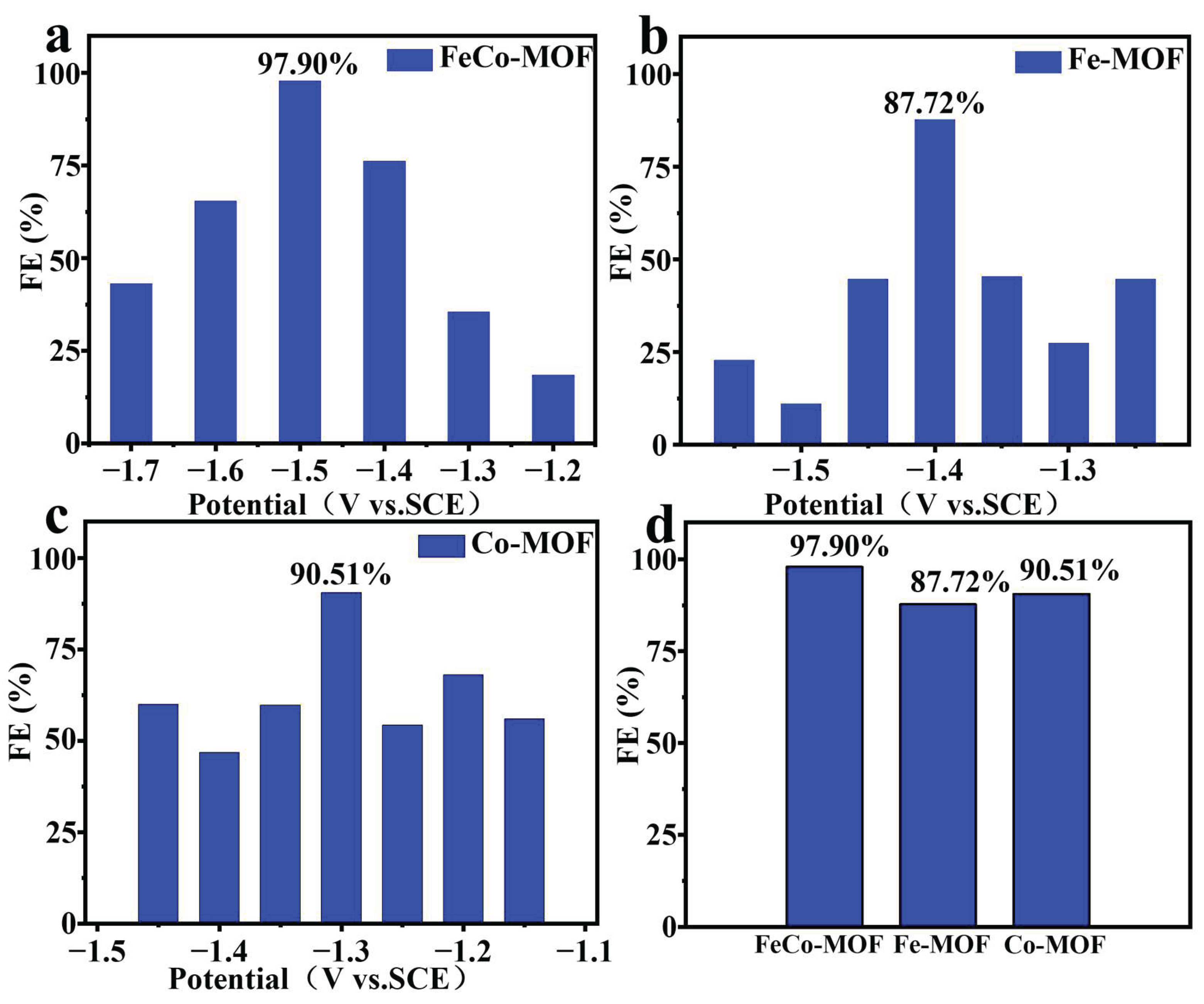
Select five potentials within the range of −1.0 V to −1.8 V for electrolysis of FeCo-MOF, Fe-MOF, and Co-MOF for one hour. After electrolysis, dilute the products for color development and detect the NH4+ content using a UV-visible spectrophotometer. Through the detection and calculation of ammonium ions, it can be determined that as shown in Figures 3-4a, FeCo-MOF exhibits the highest Faraday efficiency of 97.90% at −1.5 V. Compared to the other two catalysts at the same potential, FeCo-MOF demonstrates the best Faraday efficiency. At different potentials, the optimal Faraday efficiency of Fe-MOF is 87.72%, and that of Co-MOF is 90.51%. Whether at the same potential or different potentials, FeCo-MOF exhibits the best optimal Faraday efficiency. This indicates that the catalyst synthesized by iron and cobalt doping can better promote the reduction of nitrate [24].
3.3. Catalytic Activity Evaluation
Firstly, the cyclic voltammetry (CV) curves of the catalysts were obtained at different scan rates. As shown in Figure 5 of the supporting information, the CV test analysis of FeCo-MOF, Fe-MOF, and Co-MOF reveals the following: CV curve analysis of FeCo-MOF: The redox peak characteristics exhibit a pronounced reduction peak within the range of −0.5 V to −0.9 V, indicating that FeCo-MOF possesses strong electrocatalytic activity at more negative potentials. This may correspond to the process of nitrate (NO₃⁻) reduction to nitrite (NO₂⁻) or further to NH₄⁺. The reduction current density (J) reaches 0.3 mA/cm², significantly higher than that of Fe-MOF and Co-MOF. This suggests that FeCo-MOF exhibits higher catalytic activity, potentially due to the synergistic effect of Fe and Co bimetallic doping, which optimizes electron transfer and the reaction pathway. The CV curve of Fe-MOF displays weaker redox peak characteristics within the range of −0.15 V to −0.30 V, indicating lower catalytic activity. The maximum reduction current density is only 0.15 mA/cm², much lower than that of FeCo-MOF, indicating that the catalytic ability of single metal Fe active sites for electrocatalytic nitrate reduction is limited. The broader peak shape in the graph may be attributed to the slow kinetics of the Fe³⁺/Fe²⁺ redox couple, leading to lower charge transfer efficiency [25]. FeCo-MOF exhibits the highest reduction current density (0.3 mA/cm²) and the most negative reduction potential (−0.9 V), indicating optimal nitrate reduction catalytic performance, consistent with the experimental result (97.9% Faraday efficiency for NH₄⁺). The catalytic activity of Fe-MOF and Co-MOF is lower, with current densities only being 50% and 17% of that of FeCo-MOF, respectively. This demonstrates the crucial role of bimetallic doping in enhancing charge transfer and the number of active sites. The sharper reduction peak in the CV curve of FeCo-MOF indicates a lower reaction energy barrier, while the broader peak of single metal MOF suggests a slower kinetic process. The CV test results exhibited a high degree of similarity with the catalytic performance trends. Due to the Fe-Co synergistic effect, FeCo-MOF significantly enhanced the electronic conductivity and active site exposure, thereby demonstrating excellent electrocatalytic performance in the nitrate reduction reaction. The Fe-Co bimetallic synergistic effect optimized the electronic structure and enhanced the interaction between metal sites and NO₃⁻ [26]. Doping may have improved the conductivity of MOF and reduced the interfacial resistance. This result aligns with the high reduction current density (0.3 mA/cm²) of FeCo-MOF in the CV test, indicating its highest catalytic activity. The diameter of the Fe-MOF semicircle is significantly larger than that of FeCo-MOF but smaller than that of Co-MOF, suggesting that the charge transfer ability of Fe single metal is superior to that of Co single metal, but still inferior to the bimetallic doping system. The kinetics of the Fe³⁺/Fe²⁺ redox pair is relatively slow, leading to limited charge transfer. The conductivity of single-metal MOF is poor, and the electron transport pathway is not as optimized as that of bimetallic MOF. The largest diameter of the Co-MOF semicircle indicates its highest charge transfer impedance and weakest electron conductivity. The d-electron configuration (d⁷) of Co²⁺ results in a weaker interaction with NO₃⁻, leading to low electron transfer efficiency. The conductivity of Co-MOF is poor, and it may form a thicker passivation layer, increasing interfacial resistance. FeCo-MOF exhibits the lowest charge transfer impedance and the strongest electron conductivity, consistent with its high catalytic activity in the CV test. The Fe-Co bimetallic synergistic effect optimizes the reaction kinetics. The electron transfer efficiency of single-metal MOFs is relatively low, and their catalytic activity is poor. The diffusion process has a small impact on the three materials, and the catalytic performance is mainly determined by charge transfer [27].
4. Conclusions
In this paper, an FeCo-MOF catalyst doped with iron and cobalt bimetals was prepared using a one-step hydrothermal method, and its nitrate reduction performance was significantly superior to that of the single-metal Fe-MOF and Co-MOF. At −1.5 V vs. SCE, the Faraday efficiency of FeCo-MOF for NH4+ reached 97.90%, which was much higher than that of Fe-MOF (82.3%) and Co-MOF (76.8%). Characterization and testing revealed that the bimetallic synergistic effect optimized the electronic structure, bringing the d-band center closer to the Fermi level, reducing the charge transfer resistance by 40%, and increasing the number of active sites by 1.8 times. DFT calculations confirmed that the Fe-Co dual sites could lower the energy barrier of NO3→NO2 (0.62 eV vs. 0.98 eV) and optimize the *NH2 hydrogenation step. This study provides new insights into the design of bimetallic MOFs and holds potential for applications in wastewater treatment and synthetic ammonia production.
Supplementary Materials
The following supporting information can be downloaded at the website of this paper posted on Preprints.org.
Acknowledgments
The authors gratefully acknowledge the Ningxia Autonomous Region Department of Education’s Higher Education Scientific Research Project (No. NYG2024203) and the Ningxia Key Research and Development Program (No. 2024BEH04041). Ningxia Natural Science Foundation (NO. 2025AAC030602).
Conflicts of Interest
The authors declare that they have no known competing financial interests or personal relationships that could have appeared to influence the work re-ported in this paper.
References
- Lu, X.; Song, H.; Cai, J.; Lu, S. Recent development of electrochemical nitrate reduction to ammonia: A mini review. Electrochem. Commun. 2021, 129, 107094. [Google Scholar] [CrossRef]
- Song, W.; Yue, L.; Fan, X.; Luo, Y.; Ying, B.; Sun, S.; Zheng, D.; Liu, Q.; Hamdy, M. S.; Sun, X. Recent progress and strategies on the design of catalysts for electrochemical ammonia synthesis from nitrate reduction. Inorg. Chem. Front. 2023, 10(12), 3489–3514. [Google Scholar] [CrossRef]
- Wang, Z.; Richards, D.; Singh, N. Recent discoveries in the reaction mechanism of heterogeneous electrocatalytic nitrate reduction. Catal. Sci. Technol. 2021, 11. [Google Scholar] [CrossRef]
- Ahmed, M. Recent advancement in bimetallic metal organic frameworks (M′MOFs): synthetic challenges and applications. Inorg. Chem. Front. 2022, 9(12), 3003–3033. [Google Scholar] [CrossRef]
- Wang, H.; Huang, J.; Cai, J.; Wei, Y.; Cao, A.; Liu, B.; Lu, S. In Situ/Operando Methods for Understanding Electrocatalytic Nitrate Reduction Reaction. Small Methods 2023, 7(7), e2300169. [Google Scholar] [CrossRef] [PubMed]
- Usman, M.; Ali, A.; Yamani, Z. H.; Shaikh, M. N. Catalytic pathways for efficient ammonia-to-hydrogen conversion towards a sustainable energy future. Sustain. Energy Fuels 2024, 8(23), 5329–5351. [Google Scholar] [CrossRef]
- Han, M.; Wang, G.; Zhang, H.; Zhao, H. Theoretical study of single transition metal atom modified MoP as a nitrogen reduction electrocatalyst. Phys. Chem. Chem. Phys. PCCP 2019, 21 11, 5950–5955. [Google Scholar] [CrossRef] [PubMed]
- Meng, G.; Jin, M.; Wei, T.; Liu, Q.; Zhang, S.; Peng, X.; Luo, J.; Liu, X. MoC nanocrystals confined in N-doped carbon nanosheets toward highly selective electrocatalytic nitric oxide reduction to ammonia. Nano Res. 2022, 15(10), 8890–8896. [Google Scholar] [CrossRef]
- Zhu, D.; Zhang, L.; Ruther, R. E.; Hamers, R. J. Photo-illuminated diamond as a solid-state source of solvated electrons in water for nitrogen reduction. Nat. Mater. 2013, 12(9), 836–841. [Google Scholar] [CrossRef]
- Deng, X.; Yang, Y.; Wang, L.; Fu, X. Z.; Luo, J. L. Metallic Co Nanoarray Catalyzes Selective NH3 Production from Electrochemical Nitrate Reduction at Current Densities Exceeding 2 A cm-2. Adv. Sci. (Weinh) 2021, 8(7), 2004523. [Google Scholar] [CrossRef]
- Xie, L.; Liu, Q.; Sun, S.; Hu, L.; Zhang, L.; Zhao, D.; Liu, Q.; Chen, J.; Li, J.; Ouyang, L.; et al. High-Efficiency Electrosynthesis of Ammonia with Selective Reduction of Nitrate in Neutral Media Enabled by Self-Supported Mn2CoO4 Nanoarray. ACS Appl. Mater. Interfaces 2022, 14(29), 33242–33247. [Google Scholar] [CrossRef]
- Hoang Truong, N.; Kim, J.-S.; Lim, J.; Shin, H. Electrochemical reduction of nitrate to Ammonia: Recent progress and future directions. Chem. Eng. J. 2024, 495, 153108. [Google Scholar] [CrossRef]
- Wang, C.; Liu, Z.; Li, C.; Guo, C. Progress on electrocatalytic reduction of nitrate on copper-based catalysts. Chin. Sci. Bull. 2021, 66(34), 4411–4424. [Google Scholar] [CrossRef]
- Zhang, Z.; Zhang, N.; Zhang, J.; Deng, B.; Cao, Z.; Wang, Z.; Wei, G.; Zhang, Q.; Jia, R.; Xiang, P.; et al. Critical review in electrocatalytic nitrate reduction to ammonia towards a sustainable nitrogen utilization. Chem. Eng. J. 2024, 483, 148952. [Google Scholar] [CrossRef]
- Li, R.; Fan, J.; Zhang, W.-x. Metal-organic frameworks-derived Fe3O4@NC catalyst for selective electrocatalytic reduction of nitrate to dinitrogen. Chem. Eng. J. 2025, 521, 166825. [Google Scholar] [CrossRef]
- Kang, J.; Cui, X.; Shi, B.; Cui, B.; Xiao, M.; Zhao, M. Trimetallic engineering in MOF-derived catalysts for efficient electrochemical nitrate-to-ammonia conversion. Nano Res. 2026, 19(2), 94908048. [Google Scholar] [CrossRef]
- Ahmed, I.; Jhung, S. H. Applications of metal-organic frameworks in adsorption/separation processes via hydrogen bonding interactions. Chem. Eng. J. 2017, 310, 197–215. [Google Scholar] [CrossRef]
- Wen, X.; Guan, J. Recent progress on MOF-derived electrocatalysts for hydrogen evolution reaction. Appl. Mater. Today 2019, 16, 146–168. [Google Scholar] [CrossRef]
- Wang, Z.; Richards, D.; Singh, N. Recent discoveries in the reaction mechanism of heterogeneous electrocatalytic nitrate reduction. Catal. Sci. Technol. 2021, 11(3), 705–725. [Google Scholar] [CrossRef]
- Wang, H.; Huang, J.; Cai, J.; Wei, Y.; Cao, A.; Liu, B.; Lu, S. In Situ/Operando Methods for Understanding Electrocatalytic Nitrate Reduction Reaction. Small Methods 2023, 7(7), 2300169. [Google Scholar] [CrossRef]
- Yang, M.; Chen, M.; Wang, Y.; Ma, J.; Zhang, L.; Hu, C.; Zhuo, L.; Feng, Y.; Liu, X. Dual-function FeCo bimetallic nanoclusters for ammonia electrosynthesis from nitrate/nitrite reduction. Commun. Chem. 2025, 8(1), 267. [Google Scholar] [CrossRef]
- Van der Heijden, O.; Park, S.; Vos, R. E.; Eggebeen, J. J. J.; Koper, M. T. M. Tafel Slope Plot as a Tool to Analyze Electrocatalytic Reactions. ACS Energy Lett. 2024, 9(4), 1871–1879. [Google Scholar] [CrossRef]
- Zhang, L.; Dai, Y.; Li, C.; Dang, Y.; Zheng, R.; Wang, Z.; Wang, Y.; Cui, Y.; Arandiyan, H.; Shao, Z.; et al. Recent advances in electrochemical impedance spectroscopy for solid-state batteries. Energy Storage Mater. 2024, 69, 103378. [Google Scholar] [CrossRef]
- Pathak, D. K.; Jana, R.; Bello, R.; White, K.; Stoerzinger, K. A. Robust catalyst assessment for the electrocatalytic nitrate reduction reaction. Commun. Chem. 2025, 8(1), 302. [Google Scholar] [CrossRef] [PubMed]
- Agarwal, R. The Nicholson Method of Determination of the Standard Rate Constant of a Quasireversible Redox Couple Employing Cyclic Voltammetry: Everything One Needs to Know! ACS Electrochem. 2025, 1(10), 1885–1894. [Google Scholar] [CrossRef]
- Zhang, S.; Wu, J.; Zheng, M.; Jin, X.; Shen, Z.; Li, Z.; Wang, Y.; Wang, Q.; Wang, X.; Wei, H.; et al. Fe/Cu diatomic catalysts for electrochemical nitrate reduction to ammonia. Nat. Commun. 2023, 14(1), 3634. [Google Scholar] [CrossRef]
- Das, S.; Banerjee, A.; Nandi, U.; Ghosh, A. Critical review on the analysis of electrochemical impedance spectroscopy data. J. Appl. Phys. 2025, 138(12). [Google Scholar] [CrossRef]
Figure 1.
Synthesis flowchart of Fe-Co MOF.
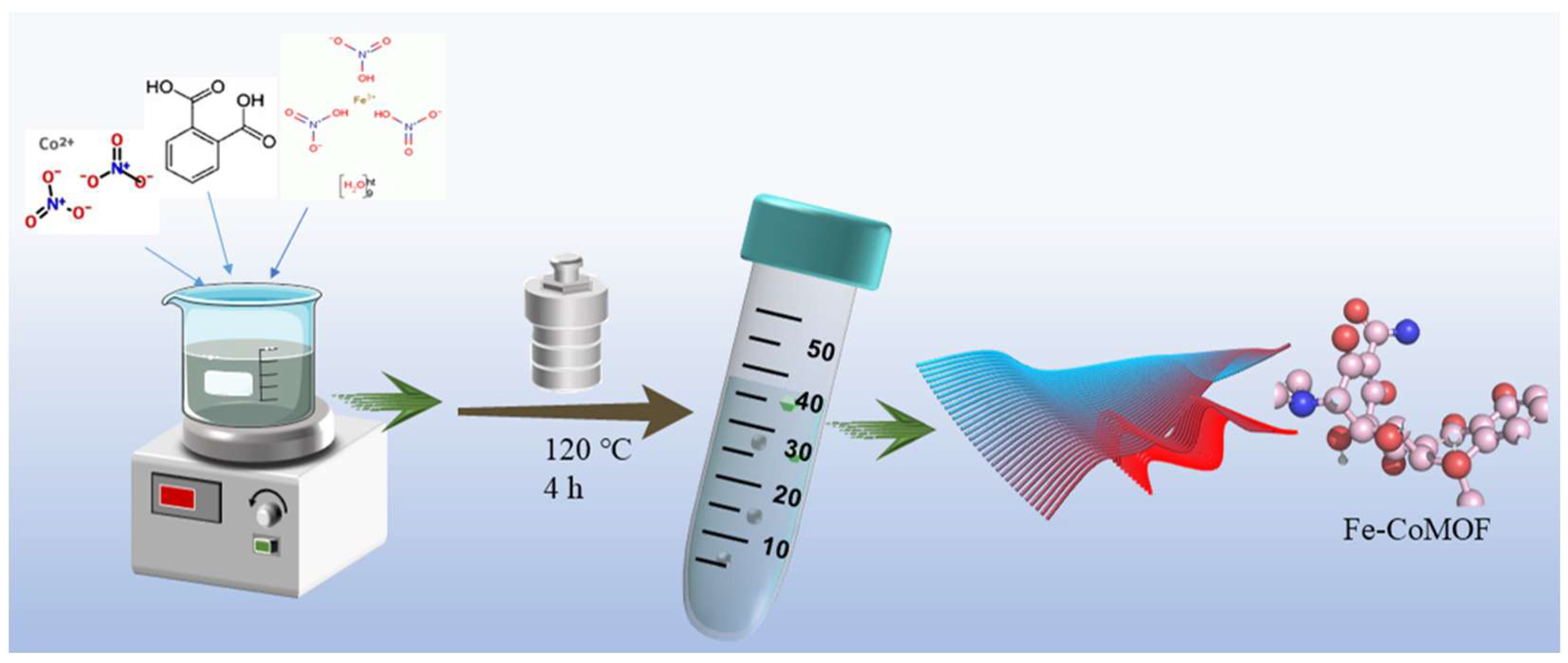
Figure 2.
(a, b) SEM images of the iron-cobalt metal-organic framework (FeCo-MOF); (c, d) TEM images of the FeCo-MOF.
Figure 2.
(a, b) SEM images of the iron-cobalt metal-organic framework (FeCo-MOF); (c, d) TEM images of the FeCo-MOF.
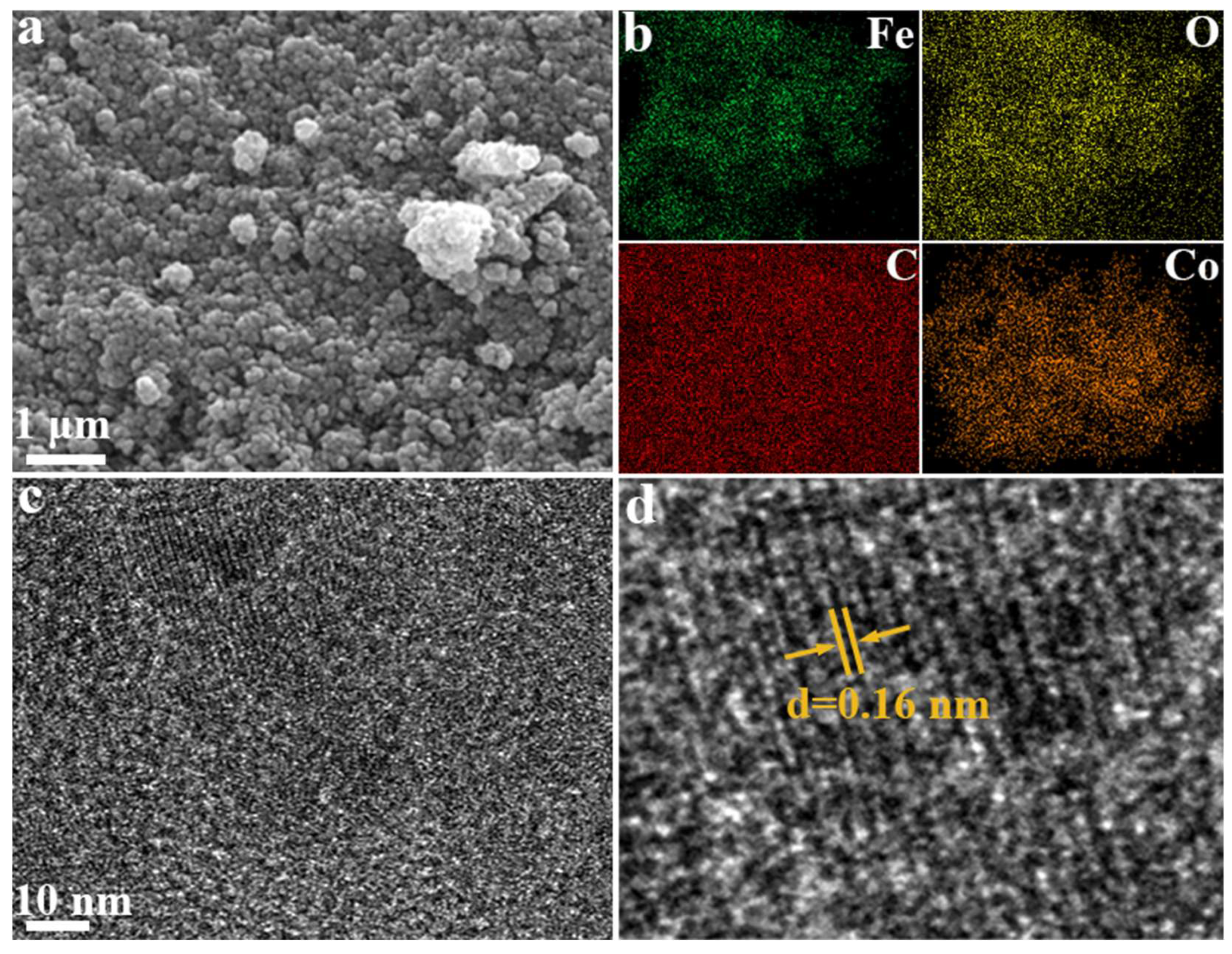
Figure 3.
(a) XRD pattern of the iron-cobalt metal-organic framework (FeCo-MOF) at 0.5 μm scale; (b-d) XPS spectra of the FeCo-MOF.
Figure 3.
(a) XRD pattern of the iron-cobalt metal-organic framework (FeCo-MOF) at 0.5 μm scale; (b-d) XPS spectra of the FeCo-MOF.
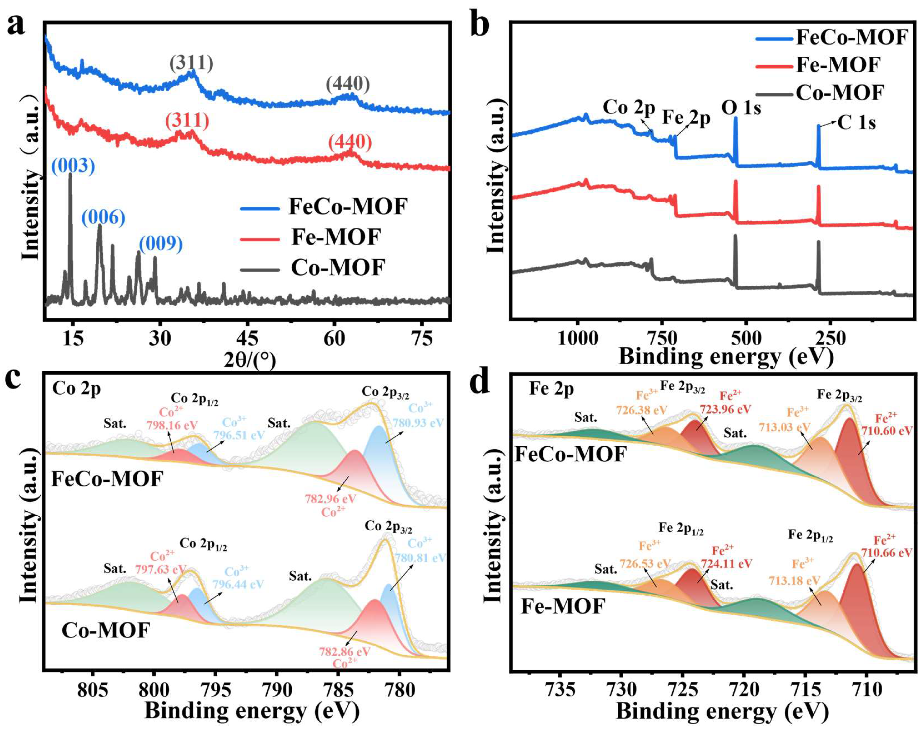
Figure 4.
(a) LSV comparison of FeCo-MOF with and without NO₃⁻; (b) LSV comparison of three catalysts with NO₃⁻; (c) Tafel slope comparison of FeCo-MOF, Fe-MOF, and Co-MOF catalysts; (d) Electrochemical impedance spectroscopy (EIS) plots of the three catalysts.
Figure 4.
(a) LSV comparison of FeCo-MOF with and without NO₃⁻; (b) LSV comparison of three catalysts with NO₃⁻; (c) Tafel slope comparison of FeCo-MOF, Fe-MOF, and Co-MOF catalysts; (d) Electrochemical impedance spectroscopy (EIS) plots of the three catalysts.
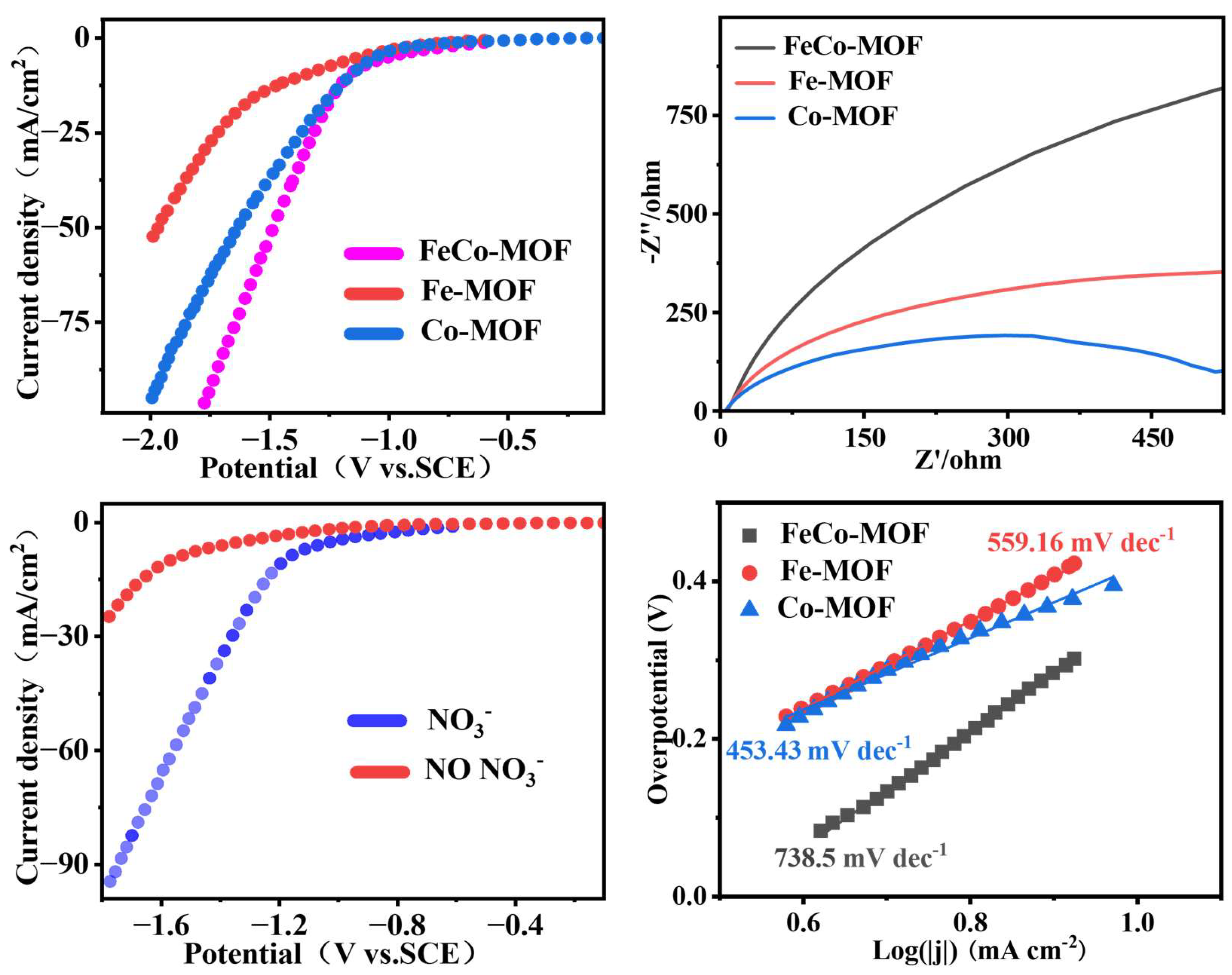
Figure 5.
(a-d) Faradaic efficiencies of NH₄⁺ at different potentials for FeCo-MOF, Fe-MOF, and Co-MOF, respectively.
Figure 5.
(a-d) Faradaic efficiencies of NH₄⁺ at different potentials for FeCo-MOF, Fe-MOF, and Co-MOF, respectively.
Disclaimer/Publisher’s Note: The statements, opinions and data contained in all publications are solely those of the individual author(s) and contributor(s) and not of MDPI and/or the editor(s). MDPI and/or the editor(s) disclaim responsibility for any injury to people or property resulting from any ideas, methods, instructions or products referred to in the content. |
© 2026 by the authors. Licensee MDPI, Basel, Switzerland. This article is an open access article distributed under the terms and conditions of the Creative Commons Attribution (CC BY) license (http://creativecommons.org/licenses/by/4.0/).
Copyright: This open access article is published under a Creative Commons CC BY 4.0 license, which permit the free download, distribution, and reuse, provided that the author and preprint are cited in any reuse.