Submitted:
15 April 2026
Posted:
16 April 2026
You are already at the latest version
Abstract
This report presents a hybrid control architecture for a series-connected string of four photovoltaic cells as a pedagogical exercise. A spintronic 4×4 crossbar is used exclusively to monitor per-cell voltages and activate the corresponding bypass MOSFETs in nanoseconds, while a conventional digital microcontroller runs a classical MPPT algorithm for string-level optimization. The note uses this hybrid “crossbar bypass + digital MPPT” architecture as an educational case study for PV shadow management.
Keywords:
photovoltaic string
; partial shading
; fast-moving shadows
; hybrid control
; spintronic crossbar
; magnetic tunnel junction
; MTJ
; bypass MOSFET
; hot-spot prevention
; MPPT
; perturb and observe
; incremental conductance
; boost converter
; analog computation
; PWM control
1. Introduction
In a series-connected PV string, fast bypass of shaded cells is essential to prevent hot-spots and to allow the remaining cells to continue delivering power. Conventional digital microcontrollers (MCUs) sample voltages sequentially, apply filtering, and execute iterative decision loops, resulting in latencies of hundreds of microseconds to milliseconds. For fast-moving shadows, this delay can cause reverse bias and energy loss.
A spintronic crossbar array can perform parallel analog computation, reading all cell voltages simultaneously and instantly identifying the weakest cell. This makes it ideal for bypass control. However, MPPT, which requires power calculation, history, and sometimes global scans, is still effectively handled by a digital algorithm.
This report presents a pedagogical exercise that combines the two: the spintronic crossbar handles bypass with nanosecond response, while the MCU runs a standard MPPT algorithm. The exercise is intentionally limited to four cells to keep the explanation simple, but the architecture is generic.
Note on scalability: in traditional digital systems, increasing the number of monitored cells tends to increase sensing, processing, and coordination burden. In a spintronic crossbar, the monitored voltages are evaluated in a single parallel analog step, so the decision path does not grow in the same way as sequential sampling. In practical systems, overall performance will still depend on sensing front-ends, routing, comparator design, and gate-driver implementation. The same hybrid concept can nevertheless be extended to larger strings by using larger crossbars (for example 16×16 or 32×32) and, where appropriate, future multi-level spintronic devices.
2. System Architecture
The system comprises:
- Four series-connected monocrystalline PV cells.
- Four MOSFET bypass switches (Q1–Q4), each across one cell.
- A spintronic 4×4 crossbar that reads the four cell voltages Vc1–Vc4 and performs an analog matrix-vector computation (MVM).
- Four current-to-voltage conversion stages (for example sense resistors or TIAs) and comparators that compare the crossbar outputs to programmable thresholds.
- A digital microcontroller (MCU) that reads string voltage V_PV and string current I_PV directly from the main power lines, executes a classical MPPT algorithm (P&O or IncCond), sends a duty cycle D (PWM) to the DC-DC converter control input, provides a programming/control line to the crossbar to set the conductance matrix G once at startup or periodically, and can optionally receive a BYPASS_EVENT digital flag when any Qk changes state.
- A DC-DC converter (boost or isolated step-up) that interfaces the PV string to a 36 V battery or DC bus.
Implementation note (converter realism): boosting directly from about 2–3 V (4 cells) to 36 V requires very high duty cycle and high input current, making efficiency and control more difficult. For laboratory demonstrations it is often easier to use clusters, for example 4 clusters in series, where each cluster contains 4 cells in series. This raises the PV input voltage to about 8–9 V at MPP and reduces converter stress. The hybrid bypass/MPPT control principles described here remain the same; only the power-stage design becomes easier.
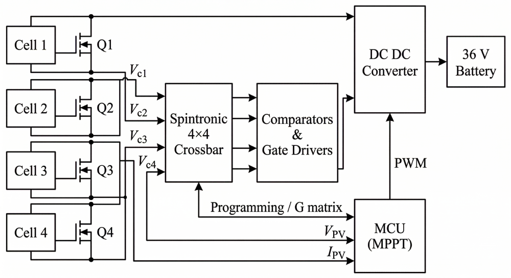
Figure 1.
Simplified block diagram of the hybrid control system. The spintronic crossbar reads Vc1–Vc4 and drives comparators that directly trigger bypass MOSFETs. The MCU reads V_PV and I_PV directly, runs MPPT, and outputs PWM to the DC-DC converter. A single programming link from the MCU sets the crossbar conductance matrix G.

3. Spintronic Crossbar for Bypass Control
3.1. Principle and Mathematical Formulation
The crossbar is programmed with a conductance matrix G so that each output channel produces a signal proportional to how much one cell voltage deviates from the string average. The four input voltages are the per-cell voltages Vc1–Vc4 measured across each cell.
Define the average cell voltage and deviations as Vavg = (Vc1 + Vc2 + Vc3 + Vc4) / 4 and ΔVk = Vck − Vavg.
One convenient choice is I = G · V with G = g · (I4 − (1/4)·11ᵀ). For N = 4 this becomes:
G = g · [ 3/4 −1/4 −1/4 −1/4
−1/4 3/4 −1/4 −1/4
−1/4 −1/4 3/4 −1/4
−1/4 −1/4 −1/4 3/4 ]
so that each output current is Ik = Σj Gkj · Vcj = g · ΔVk (up to the scale factor g).
Each crossbar column output is a current Ik. In practice it is converted to a voltage using a sense resistor or a transimpedance amplifier (TIA): Vk,out = R_TIA · Ik. A comparator then triggers bypass when Vk,out < −VTH (equivalently Ik < −ITH). A negative deviation (ΔVk < 0) means cell k is below the average; bypass is enabled only when the deviation exceeds a chosen margin to avoid triggering on normal mismatch.
3.2. Operation
- Parallel read: all cell voltages are applied to the crossbar rows simultaneously.
- Analog computation: output currents are generated in nanoseconds.
- Comparison: comparators immediately trigger gate drivers.
Turn-ON (protection) rule: when a cell becomes heavily shaded, its voltage collapses. The comparator outputs can directly enable bypass MOSFET Qk within less than 100 ns when Vk,out < VON, with VON a negative threshold corresponding to ΔVk < −ΔVTH, or when the raw cell voltage Vck approaches a safe reverse-bias limit VREV (about 0 V). To avoid chatter under fast shadows and noise, use hysteresis (VON < VOFF) and/or a latch with a minimum ON time tON,min, for example 1–10 ms. Choose ΔVTH large enough to exceed normal cell mismatch, typically on the order of tens of millivolts depending on sensing accuracy.
Turn-OFF (recovery) rule: with a MOSFET bypass ON, Vck is clamped near 0 V, so the analog path cannot directly tell when the cell has recovered. A simple solution is a periodic PROBE: (1) briefly reduce PV current, for example the MCU decreases D for a boost converter, so the string current is small; (2) open Qk for a short time tPROBE, for example 50–200 µs, and measure Vck; (3) if Vck > VOFF for the probe window, keep Qk OFF, otherwise re-enable Qk. Repeat every TPROBE, for example 10–50 ms.
Latency: the initial bypass decision is dominated by the comparator and gate-driver delays, typically below 100 ns total. The MCU does not need to sample per-cell voltages; it only (i) programs the crossbar conductance matrix G at startup, optionally updates thresholds, and (ii) runs MPPT on the string measurements. In addition, a bypass event can generate a digital flag to the MCU to accelerate MPPT re-lock.
Implementation notes (practical wiring): per-cell voltages Vc1–Vc4 are floating at different common-mode levels, so sensing typically needs differential front-ends or isolation. Gate drive for Q2–Q4 requires level shifting or isolated drivers because the MOSFET sources are not at ground. An “ideal bypass MOSFET” is often implemented with two back-to-back MOSFETs to avoid unintended conduction through the body diode. Crossbar row inputs must be high-impedance so the sensing network does not load the PV cells.
Figure 2.
Bypass decision path: Vc1–Vc4 → crossbar → current-to-voltage stage and comparators → gate drivers → MOSFETs. The comparator threshold shown in the schematic is an example after current-to-voltage conversion; in practice it is set to a margin large enough to exceed normal mismatch.
Figure 2.
Bypass decision path: Vc1–Vc4 → crossbar → current-to-voltage stage and comparators → gate drivers → MOSFETs. The comparator threshold shown in the schematic is an example after current-to-voltage conversion; in practice it is set to a margin large enough to exceed normal mismatch.

4. Analog-Digital Co-Existence: Why This Split Makes Sense
A key scientific insight of this hybrid architecture is the separation of real-time protection from optimization:
| Function | Role |
| Spintronic crossbar (analog) | Handles the protection task (bypass). This task requires the minimum possible latency to prevent hot-spot damage. The crossbar’s parallel analog nature is well suited to this, because it compares all cell voltages in a single step without sampling or iterative loops. |
| Digital MCU (digital) | Handles the optimization task (MPPT). Tracking the maximum power point involves iterative algorithms, memory of past states, and occasional global scans. Digital logic is flexible, easy to program, and can handle these tasks at a moderate update rate, for example about 10–500 Hz, without needing nanosecond response. |
This division of labor leverages the strengths of each technology: the speed of analog for protection and the flexibility of digital for optimization.
5. Classical MPPT in the Digital Domain
The MCU runs a standard MPPT algorithm, such as Perturb & Observe or Incremental Conductance, at a typical update rate of about 10–500 Hz depending on sensor bandwidth and converter dynamics. In many small systems, about 50–200 Hz is common.
It uses the string voltage V_PV and current I_PV, which reflect the combined effect of active cells and bypass state, and updates the duty cycle D of the DC-DC converter.
Since bypass decisions are made independently, the MPPT algorithm automatically adapts to the new string configuration when a bypass event occurs. For example, when a cell is bypassed the string voltage capability changes and the MPP shifts; the MPPT routine adjusts the duty cycle D to re-lock to the new operating point. Because the MPPT update rate is much slower than the bypass response, there can be a short transient where the system operates away from the MPP until the algorithm catches up. This is why the optional BYPASS_EVENT interrupt is helpful.
Figure 3.
Classical MPPT control loop. The MCU samples V_PV and I_PV, computes power, runs the MPPT algorithm, and updates the PWM duty cycle.
Figure 3.
Classical MPPT control loop. The MCU samples V_PV and I_PV, computes power, runs the MPPT algorithm, and updates the PWM duty cycle.

6. Interaction Between Bypass and MPPT
When a bypass MOSFET turns on or off, the string voltage V_PV changes almost instantaneously. The MPPT controller, running at a slower rate, detects the change on the next sample and then adjusts the duty cycle D to track the new MPP. To re-lock faster, the bypass hardware can also raise a digital BYPASS_EVENT flag, for example an interrupt to the MCU whenever any Qk changes state. The MCU can then temporarily increase the MPPT step size or run a short coarse search before returning to normal fine tracking.
Figure 4.
Timing diagram. A shading event triggers bypass in less than 100 ns. The MPPT algorithm detects the voltage drop at the next sampling instant, for example about 10 ms later, and begins tracking the new MPP.
Figure 4.
Timing diagram. A shading event triggers bypass in less than 100 ns. The MPPT algorithm detects the voltage drop at the next sampling instant, for example about 10 ms later, and begins tracking the new MPP.

7. Advantages
| Advantage | Description |
| Ultra-fast bypass | Nanosecond response prevents reverse bias and hot-spots. |
| No cell voltage sampling by MCU | Reduces MCU workload and ADC channels. |
| Parallel reading | No skew between cell measurements. |
| Simple MCU code | MPPT algorithm unchanged from classical implementation. |
| Scalability | The same crossbar can be expanded to more cells without a proportional increase in sequential decision latency, subject to practical sensing and implementation constraints. |
8. Limitations
| Limitation | Description |
| MPPT latency | The digital MPPT still introduces a delay, often about 10–100 ms, in adapting to bypass-induced voltage changes, causing brief power loss. |
| No per-cell MPPT | The crossbar only controls bypass; MPPT is still string-level, so it cannot extract the absolute maximum power under complex shading where different cells have different MPPs. |
| Additional hardware | Requires a spintronic crossbar and comparators, though the crossbar can be integrated into an ASIC. |
| Programming complexity | The conductance matrix G must be set appropriately; this may require initial calibration. |
9. Comparison with Alternative Architectures
| Architecture | Bypass Speed | MPPT Quality | Complexity | Cost |
| Fully digital MCU | Slow (ms) | String-level | Low | Low |
| Hybrid (this work) | Fast (ns) | String-level | Medium | Medium |
| Fully spintronic | Fast (ns) | Per-cell (analog) | High | High |
The hybrid approach offers a pragmatic intermediate step: it solves the most critical problem, namely fast bypass, with minimal disruption to existing MPPT designs while keeping the additional hardware manageable.
10. Conclusions
This report has presented a pedagogical exercise in which a spintronic crossbar is used exclusively for fast bypass decisions, while a classical digital MPPT algorithm continues to manage the DC-DC converter. The exercise demonstrates how the parallel analog computation of a spintronic crossbar can achieve nanosecond bypass response, eliminating the risk of hot-spots under fast shading. The digital MPPT retains its flexibility and can be implemented with standard algorithms.
Although we used a 4-cell string with a binary 4×4 crossbar, the principles are generic. The same hybrid architecture can be extended to larger strings by using larger crossbars, for example 16×16 or 32×32, and can incorporate future multi-level spintronic devices for more advanced MPPT.
Looking ahead, this hybrid architecture provides a useful framework for studying how spintronic decision elements may coexist with classical power-electronics control. Future work may explore broader integration of spintronic computing into MPPT and energy-management functions, but those directions should be treated as separate design and validation steps.
11. Economic and Practical Comparison: Hybrid vs Classical Bypass Control
This section compares the practical cost and complexity trade-offs of the proposed hybrid architecture, spintronic crossbar for bypass plus conventional MCU MPPT, against classical solutions. Because prices depend strongly on volume and integration level, the discussion is qualitative and focuses on the main cost drivers.
Reference architectures. For clarity, we compare three common options: classical passive bypass using Schottky diodes plus a conventional MPPT controller; classical active bypass using per-cell sensing plus MCU or FPGA control of MOSFET bypass plus MPPT; and the hybrid approach in which a spintronic crossbar plus fast comparators manage bypass MOSFETs while the MCU keeps a standard MPPT loop.
Cost drivers (hardware). Passive bypass is typically the lowest-cost approach: diodes are cheap and self-actuating, but they dissipate power when conducting. Active MOSFET bypass can reduce conduction losses, but it requires additional circuitry, including per-cell voltage sensing, often floating or differential, gate drivers, often level-shifted or isolated for stacked cells, and a controller fast enough to make stable decisions under rapid transients. The hybrid approach adds the crossbar device and a small analog interface, for example transimpedance and thresholding, but it can reduce the required speed, and sometimes the class, of the MCU because the real-time bypass decision is offloaded to the crossbar.
Cost drivers (engineering time and verification). A major cost in active bypass systems is firmware and verification effort: ensuring correct hysteresis, avoiding chatter, and handling corner cases under fast shadowing. In the hybrid approach, the decision is implemented in a fixed, parallel analog computation once the crossbar conductances are programmed, which can simplify timing analysis. However, the hybrid approach introduces new engineering tasks: calibrating thresholds, validating crossbar programming, and characterizing variability and drift, especially in early prototypes.
Benefit scaling: small vs large PV systems. For small PV systems such as portable, vehicle-mounted, IoT, or educational demonstrators, energy is scarce and shading is often frequent. Here, the hybrid approach can be economically attractive because even modest absolute energy gains translate into meaningful runtime extension, and the additional hardware is limited in count. For large PV installations, the dominant solutions are typically module-level bypass diodes plus string or inverter-level MPPT, and sometimes module-level power electronics. Per-cell bypass rarely scales directly due to wiring and driver complexity. The most realistic path for hybrid ideas at large scale is submodule-level integration, where shading patterns and mismatch can still cause measurable yield losses and hot-spot risk.
Why it matters for cargo bikes and cars. Mobile PV on cargo bikes or cars experiences fast time-varying shadows from trees, buildings, passing objects, and vehicle motion. These conditions create two economic pressures: frequent operation away from the optimum point reduces harvested energy, and repeated thermal stress and potential hot-spots reduce reliability. In this setting, the hybrid approach can be attractive because the crossbar can trigger bypass on a nanosecond to microsecond timescale, protecting cells and stabilizing the string quickly, while the MCU continues a conventional MPPT loop at a slower rate.
Rule-of-thumb guidance. Choose the hybrid approach when shadows are fast and frequent, the PV string current is high enough that bypass conduction losses matter, and you would otherwise need a fast, and more expensive, digital controller to manage active bypass reliably. Choose classical passive bypass when BOM cost and simplicity dominate and shading dynamics are mild; choose classical active bypass when you already require fine-grained digital control and can tolerate the higher sensing and driver complexity.

Table 1.
Hardware Cost Comparison (2026 estimates).
| System Size | Classical Digital Extra Cost | Hybrid Extra Cost (today) | Hybrid Extra Cost (projected 2028–2030) |
|---|---|---|---|
| Small mobile (200 Wp) | < 3 € | 15–30 € | < 5 € |
| Medium rooftop (5 kWp) | < 15 € | 80–150 € | < 25 € |
| Large utility (100 kWp) | < 300 € | 1,500–3,000 € | < 500 € |
Table 2.
Annual Energy Gain and Payback (realistic urban shading scenario).
| Application | Typical Daily Production (classical) | Extra kWh/year (hybrid) | Payback Time (at 0.25 €/kWh) | Additional Benefits |
|---|---|---|---|---|
| Cargo bike / small car (200 Wp) | 0.8–1.2 kWh/day | 35–90 kWh/year | 4–8 months | +150–450 km range/year, reduced battery cycling |
| Passenger car roof (400 Wp) | 1.6–2.4 kWh/day | 70–180 kWh/year | 3–7 months | Extended range, lower grid charging cost |
| Urban rooftop (5 kWp) | 4–6 kWh/day | 200–500 kWh/year | 1.5–3 years | Higher self-consumption, longer module lifetime |
| Utility-scale (100 kWp) | 120–150 MWh/year | 6–15 MWh/year | 1–2 years | Reduced hot-spot failures, lower O&M cost |
Table 3.
Annual Energy Gain—a different view.
| Application | Typical PV size | Typical PV energy | Shadow dynamics | Hybrid gain (kWh/yr) |
|---|---|---|---|---|
| Cargo bike canopy / small mobile PV | 100–300 Wp | 150–400 kWh/yr | Very fast, frequent (trees/buildings) | ≈10–60 (≈5–15%) |
| Car roof PV (auxiliary) | 400–800 Wp | 500–1,200 kWh/yr | Fast, frequent while driving | ≈30–150 (≈5–12%) |
| Residential rooftop (partially shaded) | 3–6 kWp | 4,000–9,000 kWh/yr | Mostly slow, occasional fast edges | ≈20–250 (≈0.5–3%) |
| Commercial rooftop (obstructions/HVAC) | 50–200 kWp | 60,000–300,000 kWh/yr | Mixed; some recurring shade | ≈150–2,500 (≈0.2–1%) |
| Utility-scale PV (well-designed layout) | ≥1 MWp | 1–2 GWh/yr | Usually mild (unless terrain/poles) | Often small; <0.2% unless shading is significant |
Why cars can justify higher cost (value is not only kWh). On vehicles, even modest extra PV energy can have multiple benefits: increased driving range, reduced auxiliary load on the traction battery, less deep cycling, which can improve battery lifetime, and better reliability for onboard electronics. As a rough translation, 50–150 kWh/year of extra PV energy can correspond to about 250–1,000 km/year for an EV consuming about 150–200 Wh/km, or much more for an e-bike or cargo bike using about 10–20 Wh/km.
Note on future opportunity. This section evaluates only the hybrid configuration where the spintronic crossbar manages bypass while a conventional digital controller performs MPPT. A broader opportunity may be to use the crossbar, or a related in-memory compute engine, to assist MPPT itself, especially global-MPP search under partial shading, potentially improving both energy yield and controller simplicity. That case should be treated separately from the present educational hybrid note.
12. Suggested Off-the-Shelf Components for a First Laboratory Demonstrator
This hybrid lecture note assumes a research-grade spintronic crossbar. In early experiments, it is often practical to start with commercially available parts that emulate the same functional blocks, fast per-cell comparison to bypass decision, and then replace the emulator with a real spintronic array when available.
A pragmatic step-by-step lab setup can be built from these off-the-shelf blocks:
- PV source: 4 small cells or 4 clusters on a rig, or a solar simulator / strong lamp to generate repeatable fast shadows.
- DC-DC stage with MPPT-ready control: a development board or evaluation module based on a synchronous boost or buck-boost controller, for example TI LM5176 / LM5122 family or Analog Devices LT/LTC solar controllers. For a quickest start, a commercial MPPT module can be used as the DC-DC + MPPT block while you prototype the bypass logic.
- String current sensing: a low-ohmic shunt resistor plus current-sense amplifier, for example INA180/INA181 class, feeding the MCU ADC.
- String voltage sensing: resistor divider plus MCU ADC, or an external ADC if higher resolution is needed.
- Per-cell or per-substring voltage sensing: either measure the 5 string nodes N0…N4 with dividers and compute Vc1…Vc4 digitally, or use differential front-ends / instrumentation amplifiers when higher common-mode rejection is required.
- Fast bypass decision emulator before the real crossbar: a resistor network that computes average plus fast comparators, for example LMV331/LM393-class, to produce the four BYPASS_k signals.
- Bypass power stage: low-RDS(on) MOSFETs, often back-to-back for ideal bidirectional bypass, plus appropriate gate driving or level shifting, or isolated gate drivers if the MOSFET is not ground-referenced.
- Low-loss diode replacement option: an ideal diode / smart diode controller or integrated ideal diode device, MOSFET-based, can be used to compare against a Schottky bypass in terms of temperature rise and harvested energy.
- MCU / control platform: a motor-control or power-control MCU, for example TI C2000 class, or an STM32-class MCU is typically sufficient for 100–1,000 Hz MPPT updates; the bypass logic remains asynchronous in the hybrid approach.
- Test/validation tools: an electronic load or battery emulator, oscilloscope with current probe, and a data logger to measure energy over repeated shadow sequences.
Tip for demonstrations: using 4 clusters, each cluster equal to 4 cells in series, raises PV input voltage and makes the DC-DC converter easier to design and more efficient, while still preserving the fast shadow → bypass event → MPPT re-lock behavior discussed in this note.
Acknowledgments
This work was supported by the EIC Pathfinder MultiSpin.AI, grant no. 101130046, by HORIZON-JU-Chips-2025-1-IA NeAIxt grant no. 101194172, and by HORIZON-JU-Chips-2023-1-IA EdgeAI-Trust grant no. 101139892.
Conflicts of Interest
The author is affiliated with Interactive Fully Electrical VehicleS (IFEVS). This technical note is associated with patent applications already filed in Italy. It is presented for educational and scientific discussion at system level.
Table of Acronyms
| Acronym | Meaning | Acronym | Meaning |
| ADC | Analog-to-Digital Converter | MTJ | Magnetic Tunnel Junction |
| BOM | Bill of Materials | MVM | Matrix-Vector Multiplication |
| DC-DC | Direct Current to Direct Current | PV | Photovoltaic |
| MCU | Microcontroller Unit | PWM | Pulse-Width Modulation |
| MOSFET | Metal-Oxide-Semiconductor Field-Effect Transistor | TIA | Transimpedance Amplifier |
| MPPT | Maximum Power Point Tracking |
References and Section-by-Section Reference Map
The table below links each report section to a compact set of external references. This is intended as a reading guide for students: each paragraph in a given section is supported by the references listed on the same row, plus any figure captions within that section.
| Report section(s) | Main topics | Key references |
| Abstract, 1 | Motivation; fast shadows; why hybrid (crossbar bypass + digital MPPT). | [3,5,9] |
| 2 | PV string architecture; boost DC–DC as controllable input impedance; measurement signals. | [1,2,3] |
| 3 | Spintronic crossbar/MTJ basics; analog MVM (I = G·V); comparator-style bypass decisions; PROBE recovery concept. | [9,10,11,12] |
| 4–5 | Why split analog bypass vs digital MPPT; MPPT fundamentals and update-rate limits. | [2,3,4] |
| 6–7 | Interaction between bypass and MPPT; partial shading, local/global maxima; benefits of fast bypass events. | [3,5,6,7] |
| 8–10 | Limitations; alternative architectures; comparison; concluding remarks. | [3,6,9] |
| 11 | Economic/energy impact; losses in bypass elements; application-dependent value (mobile PV). | [6,7,8,12] |
| 12 | Off-the-shelf experimentation blocks; emulation strategy; practical lab starting point. | [2,6,12] |
References
- Messenger, Roger A.; Ventre, Jerry. Photovoltaic Systems Engineering, 3rd ed.; CRC Press: Boca Raton, FL, 2010. [Google Scholar]
- Erickson, Robert W.; Maksimović, Dragan. Fundamentals of Power Electronics, 2nd ed.; Springer: Boston, MA, 2001. [Google Scholar]
- Esram, Trishan; Chapman, Patrick L. Comparison of Photovoltaic Array Maximum Power Point Tracking Techniques. IEEE Transactions on Energy Conversion 2007, vol. 22(no. 2), 439–449. [Google Scholar] [CrossRef]
- Femia, Nicola; Petrone, Giovanni; Spagnuolo, Giovanni; Vitelli, Massimo. Optimization of Perturb and Observe Maximum Power Point Tracking Method. IEEE Transactions on Power Electronics 2005, vol. 20(no. 4), 963–973. [Google Scholar] [CrossRef]
- Patel, Hiren; Agarwal, Vivek. Maximum Power Point Tracking Scheme for PV Systems Operating Under Partially Shaded Conditions. IEEE Transactions on Industrial Electronics 2008, vol. 55(no. 4), 1689–1698. [Google Scholar] [CrossRef]
- Vieira, Romênia G.; de Araújo, Fábio M. U.; Dhimish, Mahmoud; Guerra, Maria I. S. A Comprehensive Review on Bypass Diode Application on Photovoltaic Modules. Energies 2020, vol. 13(no. 10), 2472. [Google Scholar] [CrossRef]
- Pannebakker, Boudewijn B.; de Waal, Arjen C.; van Sark, Wilfried G. J. H. M. Photovoltaics in the Shade: One Bypass Diode per Solar Cell Revisited. Progress in Photovoltaics: Research and Applications 2017, vol. 25(no. 10), 836–849. [Google Scholar] [CrossRef]
- Teo, J. C.; Tan, Rodney H. G.; Mok, V. H.; Ramachandaramurthy, Vigna K.; Tan, Chia Kwang. Impact of Bypass Diode Forward Voltage on Maximum Power of a Photovoltaic System under Partial Shading Conditions. Energy 2020, vol. 191, 116491. [Google Scholar] [CrossRef]
- Grollier, Julie; Querlioz, Damien; Camsari, Kerem Y.; Everschor-Sitte, Karin; Fukami, Shunsuke; Stiles, Mark D. Neuromorphic Spintronics. Nature Electronics 2020, vol. 3(no. 7), 360–370. [Google Scholar] [CrossRef] [PubMed]
- Everspin Technologies, “MTJ Storage Element,” product technology note, accessed April 2026. No DOI available. No DOI available.
- Borders, William A.; Madhavan, Advait; Daniels, Matthew W.; Georgiou, Vasileia; Lueker-Boden, Martin; Santos, Tiffany S.; Braganca, Patrick M.; Stiles, Mark D.; McClelland, Jabez J.; Hoskins, Brian D. Measurement-driven Neural-Network Training for Integrated Magnetic Tunnel Junction Arrays. Physical Review Applied 2024, vol. 21, article 054028. [Google Scholar] [CrossRef]
- Pennisi, Salvatore; Pulvirenti, Francesco; La Scala, Amedeo. Low-Power Cool Bypass Switch for Hot Spot Prevention in Photovoltaic Panels. ETRI Journal 2011, vol. 33(no. 6), 880–886. [Google Scholar] [CrossRef]
Disclaimer/Publisher’s Note: The statements, opinions and data contained in all publications are solely those of the individual author(s) and contributor(s) and not of MDPI and/or the editor(s). MDPI and/or the editor(s) disclaim responsibility for any injury to people or property resulting from any ideas, methods, instructions or products referred to in the content. |
© 2026 by the authors. Licensee MDPI, Basel, Switzerland. This article is an open access article distributed under the terms and conditions of the Creative Commons Attribution (CC BY) license (http://creativecommons.org/licenses/by/4.0/).
Copyright: This open access article is published under a Creative Commons CC BY 4.0 license, which permit the free download, distribution, and reuse, provided that the author and preprint are cited in any reuse.


