Submitted:
14 April 2026
Posted:
15 April 2026
You are already at the latest version
Abstract
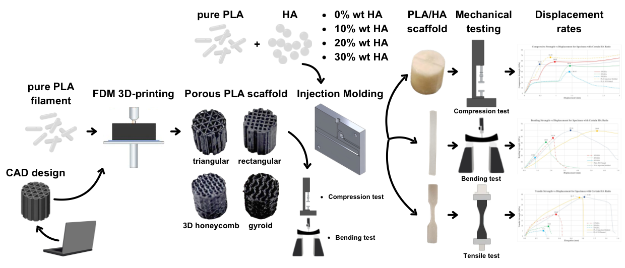
Bone tissue engineering requires biomimetic materials, but pure polylactic acid (PLA) lacks osteoinductivity and produces acidic byproducts during degradation. To address these limitations, this study fabricated PLA scaffolds using fused-deposition modeling with four distinct lattice structures (rectangular, triangular, gyroid, and honeycomb) and incorporated hydroxyapatite (HA) at ratios of 0%, 10%, 20%, and 30% via injection molding. Mechanical properties were evaluated through compression, bending, and tensile testing. The results revealed that increasing HA content significantly reduced structural strength and increased brittleness. Specifically, specimens with 30% HA showed a 50% reduction in bending strength, while tensile strength dropped by approximately 46% at just 10% HA. Although the triangular lattice maximized absolute load capacity, the rectangular lattice provided a superior load-to-weight ratio and greater plastic deformation before fracture. Consequently, these findings suggest that the rectangular pattern with 70% infill density demonstrates the most suitable mechanical properties combined with limited HA addition (< 10%) to balance necessary mechanical integrity with the enhanced bioactivity required for repairing large bone defects. These PLA/HA composite scaffolds offer a promising approach for advanced bone tissue regeneration.
Keywords:
biomaterial
; scaffold
; polylactic acid
; hydroxyapatite
; 3D printing
; fused deposition modeling
1. Introduction
Bone defect is a frequent condition resulted from traumatic injuries, age-related degenerative diseases, tumors or infections that requires reconstruction [1,2]. More than 2.2 million bone graft procedures are performed worldwide with the incidence rate expected to grow by 13% each year [3,4]. Bone graft procedures can be done by the use of autografts, allografts and biomaterial-based bone graft substitutes [5]. Autologous bone is widely recognized as the gold standard for bone graft material since it provides all three essential properties for bone regeneration: osteogenic, osteoconductive and osteoinductive [4,6]. Despite these advantages, the use of autografts has significant drawbacks, including limited availability, secondary injuries and donor-site morbidity with an associated 8-39% complication rate [7,8,9].
Bone tissue engineering is rapidly developing biomaterial-based alternatives to autografts, aiming to overcome the above-described limitations by leveraging advanced scaffolds, bioactive materials, and fabrication techniques [10,11,12]. Among other synthetic polymers, polylactic acid (PLA) is currently used extensively in medical implants. As a favorable artificial polymer, most synthetic bone graft use PLA as its base due to its osteoconductive matrix, biocompatibility and acceptability by bone [13,14]. PLA has medium degradation rate and was influenced by its molecular weight. The lower the molecular weight, the higher the degradation rate which is suitable as a substitute for bone tissue growth rate [15]. PLA is widely used for 3D-printed bone scaffolds due to its processability, but pure PLA has low osteoinductivity and produces acidic degradation byproducts [16,17,18]. To overcome these drawbacks, combining PLA with bioactive ceramics like hydroxyapatite (HA) significantly improves its suitability for bone tissue engineering because it can buffer acidic degradation, enhances osteoinductivity and improves mechanical properties [14,16].
Hydroxyapatite is extensively used as a bone substitute due to its high osteoconductivity and biocompatibility, closely mimicking natural bone mineral [19,20]. HA are made up of calcium and phosphate ions, which are naturally occurring substances in the body [4]. No studies have reported any harmful local or systemic inflammatory reactions as a result of using this material. Thus, HA has been proven to be safe as bone substitute material [21]. While pure HA scaffolds are excellent for bioactivity and bone integration, their mechanical weaknesses restrict their use in load-bearing sites [22]. Composite strategies, especially with polymers, are essential to achieve the mechanical robustness required for clinical bone repair [23,24].
Incorporating bioactive ceramics like HA into PLA filaments enhances osteoconductivity and helps neutralize acidic PLA degradation byproducts, creating composite scaffolds with improved biological and structural properties [25,26]. PLA/HA composite scaffolds also show enhanced biocompatibility and bioactivity for bone tissue engineering without increasing inflammatory responses compared to controls [14,16]. Lattice structure, commonly known as infill pattern, is a critical design parameter for optimizing PLA scaffolds, enabling the fabrication of constructs that closely replicate natural bone while meeting both mechanical and regenerative requirements [27,28,29]. Consequently, PLA/HA scaffolds may be a promising candidate for clinical bone repair applications. There is significant variability in scaffold fabrication methods and HA ratios making it difficult to determine optimal HA content for bone regeneration [17]. Across many studies, fused-deposition modeling (FDM) is consistently described as a promising technology for tissue engineering scaffolds because it enables solvent-free printing of diverse bioactive and biocompatible polymers into porous, patient-specific architectures with tunable mechanical properties making it well suited for bone regeneration [30,31,32].
This study systemically investigates 3D-printed PLA/HA composite scaffolds fabricated via FDM with varying HA ratios and four infill patterns (rectangular, triangular, gyroid, and 3D honeycomb). The scaffolds were further analyzed to assess their structural characteristics by performing compressive, bending, and tensile test to identify mechanically balanced designs for bone tissue engineering.
2. Materials and Methods
2.1. Materials
The materials used in this study included PLA as the polymer matrix and HA as the bioactive filler. The raw material PLA used are in form of ±1 mm pellets. Porous PLA scaffolds were fabricated via FDM-based 3D printing technology that uses a heated nozzle to extrude thermoplastic material layer by layer. Four HA loading content of 0%, 10%, 20%, and 30%wt HA were prepared; the 0% mixture served as the pure PLA control. Due to cost and supply limitation in Indonesia, the HA used was conventional (micron-scale) hydroxyapatite rather than nano-hydroxyapatite (n-HA), which limited filament uniformity but still provided osteoconductive sites and acid-buffering capability.
2.2. Scaffold Design
When designing a 3D-printed component, the designer has several alternatives: completely filling the parts, which requires substantial time and material, thus increasing costs, but offers enhanced mechanical strength, or utilizing infill patterns to mimic certain mechanical properties and ensure stability while reducing weight. Infill patterns are therefore important when it comes to optimizing for strength.
This study limited the infill patterns to only four patterns that are available on PrusaSlicer software for specific infill density to produce with 30% porosity. Four lattice geometries were generated in PrusaSlicer: (1) rectangular pattern, (2) triangular pattern, (3) gyroid pattern, and (4) 3D honeycomb pattern. Based on prior study on mechanical behaviors through compression test on fourteen common infill patterns, the author selects the two highest-ranking patterns based on strength-to-weight ratio: rectangular and triangular [33]. The other two patterns are gyroid and 3D honeycomb; both are reported to exhibit high mechanical strength [34]. 3D honeycomb infill patterns are optimal for maximizing compressive and tensile strength in bone scaffolds, while gyroid patterns provide exceptional resistance to shear and complex loading, along with high fatigue durability and biological compatibility [35,36,37,38]. Figure 1 illustrates the models’ geometrical of each pattern serving as a visual reference in the design process. These models were defined to ensure that the intended geometrical variations were accurately reflected in the scaffold architecture prior to final modeling.
Previous research has provided evidence that macropore size of porous scaffolds ranging from 100–500 µm have already capable of demonstrated the ability to effectively facilitate osteogenic cell migration, ensuring ample fluid transport and vascularization [39,40,41]. The macropore size of the scaffold manufactured in this study was measured 700–1200 µm; above the 300–500 µm range recommended as the requirements. The shape of each pore follows the underlying infill pattern: rectangular grids produce straight-line channels, triangular infill creates intersecting triangular voids, gyroid forms a continuous, triply-periodic minimal surface (TPMS) and honeycomb yields stacked hexagonal cells.
A cylinder-shaped porous scaffold with both the diameter and height of 10 mm was designed using Solidworks software. Subsequently, the design was saved as STL file for further alteration in PrusaSlicer software. The printing path of the 3D model was exported as G-code file using PrusaSlicer software with built in selection of internal structure and infill density of the design. The printing parameters was set as follows: the layer height of 0.2 mm, the speed of the nozzle moving of 60 mm/s and the perimeter was set to 0 because the purpose is to measure the mechanical properties of the internal structure. The scaffold was then fabricated by importing the G-code file to Prusa i3 MK3S+ machine for the printing of the porous scaffold.
Three-dimensional solid models were designed using CAD software before importing to FDM software. The pure PLA samples for the internal structure experiments were fabricated by FDM printer (Prusa i3 MK3S+) uses a heated nozzle to extrude thermoplastic material layer by layer. To achieve comparable porosity, rectangular, and triangular patterns were printed at 70% infill density, while gyroid and 3D honeycomb were printed at 40% infill. Mechanical tests’ specimens were printed under the fixed parameters for FDM printing summarized in Table 1.
2.3. Fabrication of Scaffolds
Micron-scaled HA powder was blended with neat PLA at 0%, 10%, 20%, and 30%wt HA. Because the PLA/HA scaffold could not be extruded reliably (nozzle clogging), the test specimens were produced by a manually-operated injection molding machine. PLA pre-mixed with specified HA ratios was heated to 165–170°C in a chamber, then held for 1–2 minutes and cooled before machining to final dimensions. Once the material was fully melted, the mold was secured within the clamp, and the molten PLA/HA mixture was rapidly injected into the aluminum cavity molds by actuating the lever.
Mechanical testing specimens comply with the appropriate standard and meet the specifications given for the shape and dimension of the test specimen as well as test machine requirements. The compressive properties followed ISO 604-2002 on cylindrical specimens (10 ± 2 mm for diameter and height of the cylinder) at a cross-head speed of 1 mm s⁻¹ to record load–displacement curves and determine ultimate compressive load and deformation behavior for each internal-structure pattern and HA content. Flexural properties were built according to ASTM D790-17 using a 3-point flexure fixture with a 51.2 mm support span; the test measured load versus deflection to obtain ultimate bending strength and load-to-weight ratios for the four lattice designs. Due to machine limitation and time constraints, the bending test specimen geometry is determined as follows: 13 mm for thickness, 25 mm for width, 78 mm for outer span and 117 mm for specimen length. The tensile properties were assessed per ASTM D638-14 on Type V dog-bone specimens at 1 mm min⁻¹, providing ultimate tensile strength and ductility data for both pure PLA and PLA/HA composites.
For FDM 3D-printed specimens, surface finishing or machining is unnecessary, as no supports are required, and the areas intended for compression or bending are sufficiently smooth. However, injection molded specimens retain excess material post-separation from the mold, which requires machining to achieve clean surfaces. Bench grinders and struers grinding machines are used to machine the specimen’s surfaces. While struers grinding uses abrasive paper to smooth the specimen’s surface, bench grinding is used to eliminate superfluous materials following the injection molding process. 3D printed scaffolds are presented in Figure 2.
2.4. Determination of Mechanical Properties
To evaluate the mechanical properties of 3D-printed PLA/HA scaffold, two experimental series were conducted. The first series investigated the influence of internal architecture by fabricating pure-PLA scaffolds with rectangular, triangular, gyroid and 3D honeycomb infill patterns (70% density for rectangular/triangular, 40% density for gyroid/honeycomb) and comparing their compressive, bending and tensile responses. The second series examined the effect of HA reinforcement which produces solid specimens through injection molding containing 0%, 10%, 20%, and 30%wt HA. Each batch was subjected to the same three mechanical testing to evaluate how increasing HA ratio alters strength, stiffness and brittleness. In vitro studies consistently show that HA at low concentrations (0–5%) does not inhibit cell proliferation, while higher HA content can significantly alter scaffold mechanics and printability [39,40,41]. Low HA loadings (around 0-10%) in printable composites consistently support cell attachment and proliferation with no meaningful cytotoxicity, including for fibroblasts, chondrocytes, and osteogenic cells [42,43,44]. As HA content rises toward and above ~30%, materials generally become stiffer, more brittle, and harder to print with high shape fidelity, which can limit scaffold performance [43,45]. Crosslinking and polymer blending can help optimize these properties for specific applications [46]. Therefore, this study limits the selected HA ratio to 0%, 10%, 20%, and 30% to be incorporated with PLA scaffolds. These experimental procedures together identified the optimal scaffold geometry and HA content for load-bearing bone defect repair applications.
3. Results and Discussion
3.1. Fabrication and Characterization of 3D-Printed PLA/HA Composite Scaffolds
Unlike any other soft tissue, bone fracture heals through the regenerative process of forming the new bone rather than developing fibrotic tissue [47,48]. Bone healing requires significant elements: osteogenic cells, osteoinductive effect to promote bone growth and osteoconductive matrix as a structural framework supporting bone growth [4,6]. As a gold standard of bone substitution, autograft has limited supply of tissue, morbidity at the donor site and ineffective operative procedures [8]. On the other side, allograft carry the risk of rejection issue and disease transmission [49]. Due to notable disadvantages of both autograft and allograft as reported, many new synthetic bone substitutes are being researched as an emerging material for bone graft. Although PLA are considered as the most appropriate material since it has good bone conductivity and degradation, it is still lacking of osteoinductive effect and produces acidic substance when degraded [50]. Due to its well-known limitations, modification has been made by adding HA into the scaffolds to improve the degradation rate and stimulating osteogenesis [6]. In one of the studies assessing the clinical outcomes of patient-specific bioceramic implants, the majority of patients recovered well with minimal complications, thereby highlighting the osteoinductive properties of HA [50]. However, subsequent study indicated that the intrinsic mechanical strength of HA is insufficient for the reconstruction of extensive bone defects [51]. According to several studies, adding HA to the scaffolds will lower the mechanical strength. The internal structure is also critical in affecting the mechanical property and bioactivity of the scaffold. Higher porosity will enhance proliferation of cells, cell attachment, and degrade rate but will reduce mechanical strength.
The ideal scaffold for bone tissue engineering should exhibit superior biocompatibility, controlled biodegradability and adequate mechanical integrity to promote effective bone regeneration [52,53]. Various biopolymers have been explored to fabricate scaffolds with other properties to develop the ideal bone graft material. For instance, a study developed polylactic acid PLA/HA composite scaffolds that have huge potential for tissue engineering and restoring maxillofacial defects [54]. The synthetic HA were known for supporting new bone formation, osteogenic marker expression and matrix mineralization [55]. While PLA is recognized for its excellent biocompatibility and biodegradability, it still has relatively low mechanical strength and osteoconductivity [50]. Based upon the problem, there is the need to optimize and characterize the effect of ratio of HA in PLA scaffold and internal structure of the structural framework to ensure the porosity are high enough while also maintaining the mechanical properties (compressive, bending, and tensile) of the scaffolds model. Consequently, this study combined PLA/HA scaffold with certain ratio of HA (0%, 10%, 20%, and 30%) and fabricated the internal structure to achieved the composite scaffolds with enhanced mechanical properties and overall performance compared to the autologous bone as the best-known material for bone graft.
The addition of HA into PLA scaffolds offers numerous advantages, notably enhancing osteoinductive capabilities by facilitating cellular interactions that promote bone formation. Multiple investigations have demonstrated that integrating bioactive ceramics with biodegradable polymers, such as in PLA/HA composites, effectively balances bioactivity and mechanical integrity within the scaffold structure [50]. The addition of HA as a filler results in a uniform distribution of HA particles on the scaffold surface, thereby providing abundant bioactive sites conducive to bone regeneration. Furthermore, the degradation rate of PLA/HA scaffolds is positively correlated with HA content, attributable to the higher biodegradability of HA compared to PLA [13]. This accelerated degradation is advantageous, as it permits more rapid replacement of the scaffold by newly formed bone tissue. Additionally, increased HA content enhances scaffold porosity, which improves water absorption and further accelerates degradation rates.
Hydroxyapatite improves the bioactivity of PLA-based scaffolds by providing osteoconductive sites that favor cell attachment and by neutralizing the acidic by-products released during PLA degradation, which helps to maintain a more favorable local pH for bone formation [25]. The presence of HA also accelerates overall scaffold degradation, not because HA itself is more biodegradable than PLA, but because the HA particles increase porosity and water uptake and because they buffer the acidic environment.
3.2. Compression Test Results
Compression tests were conducted on pure PLA scaffold with varying infill patterns (Figure 3B and C) to determine the behavior of all four types of specimens. Figure 3D shows the result of all compressive tests that have been done. The result revealed that triangular scaffolds reached the highest ultimate load (3.25 kN) followed closely by rectangular (3.20 kN), whereas gyroid and 3D honeycomb were weaker (1.32 kN and 1.62 kN). In three-point bending, rectangular and triangular patterns delivered the greatest ultimate loads (≈408 N and 415 N) and specific load ratios, while gyroid and 3D honey-comb exhibited lower bending strength but higher toughness. Results of the bending test can be seen in Figure 4. Thus, increasing porosity (lower infill density) reduces compressive and bending strength, while the rectangular geometry provides the best load-to-weight performance for a scaffold with 700–1200 µm pores. The comparison of force and displacement curves of each specimen underwent compression test can be seen in Figure 3E.
As shown in Figure 3F, the highest ultimate load for compressive test was observed in rectangular pattern followed by triangular pattern. On the other hand, gyroid and 3D honeycomb pattern are significantly lower in terms of specific load and ultimate load for compression tests.
Although gyroid pattern has highest fracture toughness which makes it suitable for bone scaffold where failure or even fracture have possibility of injuring the patients, the maximum load that the specimen can withstand before it fails under bending are the lowest among other patterns. Considering the requirement for bone scaffold, even if the specimen does not fracture, it is still considered fail and as bone scaffold will works as temporary support for bone, rectangular pattern is more suitable to be used as bone scaffold internal structure compared to triangular pattern.
3.3. Bending Test Results
The bending (three-point flexural) test was performed to evaluate how the scaffold behaves when it is subjected to a bending moment, which simulates the combination of tensile and compressive stresses that a bone implant would experience in the body. It provides the flexural strength (the maximum load the part can carry before breaking) and the flexural modulus (stiffness during bending), reveals the elastic-plastic transition, and shows how much plastic deformation the scaffold can tolerate before fracture. Figure 4 shows the physical condition of 3D-printed pure PLA scaffolds of each infill patterns after the bending test.
Results of the bending test can be seen in Figure 5. The three-point bending tests on pure-PLA scaffolds showed that the rectangular and triangular infill patterns (both printed at 70% infill density) carried the greatest loads, while the gyroid and 3D honeycomb patterns (printed at 40 % density) were much weaker. The rectangular specimen reached an ultimate bending load of about 408 N (≈ 11.3 MPa) and the triangular 415 N (≈ 11.5 MPa), giving these two designs the highest load-to-weight ratios. In contrast, the gyroid only sustained ~205 N (≈ 5.7 MPa) and the honeycomb ~243 N (≈ 6.7 MPa). The load and displacement curves reveal that the gyroid and 3D honeycomb specimens deformed over a larger displacement before failure, indicating higher ductility but lower strength, whereas the rectangular and triangular parts fractured at lower deflection (~5-6 mm) with a sharp drop after the ultimate load. All four patterns displayed a clear elastic region, a short plateau and a rapid rise in stress at densification, which is typical for porous PLA behavior.
Prior research that studies the compressive strength result of 3D-printed parts with various infill patterns found that rectangular and triangular infill was more prone to barreling and had lower compressive strength than most infill patterns due to it being less dense and have higher porosity compared to other patterns [56]. However, the test result in this study showed that rectangular and triangular infill was stronger than gyroid and 3D honeycomb infill. Although the size and shape of the test samples are the same, this occurs due to the infill density that was not the same for all four infill patterns at which the rectangular and triangular infill was printed at a higher density than the gyroid and honeycomb infill. Rectangular patterns with 70% infill density can withstand high bending loads while exhibiting a greater capacity for plastic deformation compared to the other evaluated patterns. The result from several studies revealed that the honeycomb infill pattern had the highest compressive strength, followed by the gyroid infill pattern, the rectangular infill pattern and the triangular infill pattern if all has the same infill density [57,58]. Other research indicate that the rectangular pattern may lack appropriate load-bearing capacity and effective stress distribution, leading to diminished total tensile strength [59].
3.4. Effects of HA on Mechanical Properties of PLA scaffolds
All HA-containing specimens were fabricated by manual injection molding as an attempt to extrude a PLA/HA filament for FDM repeatedly failed due to nozzle clogging, so the 3D-printed samples consisted only of pure PLA. HA addition did not result in a uniform particle distribution. Higher HA ratios produced noticeable clumping, voids and surface roughness in the molded parts. Mechanically, increasing HA content reduced strength in every test: compressive, bending and tensile capacities declined progressively. Moreover, the material became markedly more brittle, with 50% loss in tensile strength at 20%, and 30% HA ratio [14]. As a result, the HA-to-PLA ratio must be carefully optimized to balance mechanical integrity and bioactivity in bone scaffolds.
Several studies have proven that adding HA as additive materials to PLA for bone scaffold will enhance the scaffold’s biological activity and can accelerate the degradation rate of the scaffold. However, on the premise of mechanical properties of the scaffold, adding HA will directly change the microstructure of PLA matrix which in turn will affect the microstructure of scaffold’s matrix and was directly reflected in its mechanical properties. As a limitation, this study not cover other problems that are not connected to the mechanical properties of the scaffold and theoretical bioactivity of the scaffolds, such as in vitro and in vivo experiments to evaluate biocompatibility, cytotoxicity, antibacterial, osteogenesis induction, and other biological tests of the scaffolds which requires further investigation. In addition to mechanical tests, future studies can examine hardness values of the scaffold.
3.4.1. Compressive Test
After being subjected to compressive load, the deformed specimen is found to experience barreling even though the FDM printer was set for 100% infill density with rectilinear pattern which means that the specimen supposed to be solid. But in the 3D-printed specimen with 0% HA, the specimen still experiences barreling which indicates that there are still voids available on the specimens. This is because 100% infill density refers to the percentage of the part that is filled with printed material, not the percentage of the printed material that is solid. This means that there will still be voids that can be caused by the printing process itself or the printing parameters that creates gaps. These gaps cause localized instability since the specimen is not able to withstand the load uniformly and causes the surface to bend.
After analyzing the strength vs displacement graph for several types of PLA/HA specimen, it can be seen that adding more HA will make the ultimate compressive strength of the scaffold weaker as it becomes more brittle and makes the scaffold less resistant to compressive strength. Up until 20% HA ratio, the specimen still shows similar curve which means that mechanical behavior of 0%, 10% and 20% HA specimen are still similar. Although for 30% HA ratio, the curve change significantly that can be seen in the graph after failure the specimen immediately fracture which is one of characteristic of brittle materials as seen in Figure 6.
Our compressive testing revealed that increasing the proportion of HA into the PLA/HA bone scaffold leads to a reduction in compressive strength. The comparison between each HA content can be seen in Figure 7. These finding is consistent with previous reports, which note that while HA enhances bioactivity, it possesses inherently lower mechanical strength compared to natural bone, especially in its pure or highly concentrated form [60].
3.4.2. Bending Test
The force-displacement relationship of each HA ratio was displayed on Figure 8, and it is very clear that the higher the HA ratio, the lower the ultimate bending strength that the materials could support. There are significant differences between pure PLA and 10% HA specimen but when increase into 20% of HA, the reduction is only 14.1%. However, if the percentage of HA keep increased, the bending strength of the specimen drops significantly more than 50% and the specimen becomes more brittle where the displacement that the 30% specimen could withstand is less than 1 mm. On the other hand, if comparing between injection molded and 3D-printing pure PLA, it can be seen that 3D-printing has similar ultimate strength compared to injection molded but the displacement location is much higher. This phenomenon possible to occurs due to the existence of residual stress on 3D printed specimen where heating and cooling is done continuously layer-by-layer and also faster cooling rate since the specimen are exposed to air. The occurrence of residual stress will impact the plastic deformation of the material and makes the specimen deform more before failing.
The bending test results demonstrate a negative correlation between HA ratio and bending strength. As the HA content increases, the scaffold’s ability to withstand flexural forces reduces. This observation aligns with the understanding that HA, while providing a favorable environment for bone ingrowth, lacks the flexibility and resilience required to resist bending stresses [21,61]. The mechanical mismatch between HA-rich scaffolds and the surrounding bone tissue may also contribute to stress concentrations at the bone-implant interface, potentially leading to microfractures or implant failure under repetitive loading. Figure 9 shows the comparison of bending test results.
3.4.3. Tensile Test
Analyzing from the deformed specimen for 0%, 10%, 20% and 30% injection molded specimen, it can be seen that the higher the HA ratio, the brittle the specimen is and the more prone it is to fracture. On top of that, due to the dimension of the specimen and the manufacturing process, adding more HA will makes the specimen shape becomes deformed when it is separated from the mold as it becomes too brittle. During the experiment, the 20% and 30% HA specimen becomes too brittle that it can be fractured even by hand and sometimes the specimen broke when places being in the grips of the testing machine due to the pre-load given. According to Figure 10, adding even 10% of HA also significantly decrease the tensile strength of the specimen by 43.8% while adding another 10% HA will reduce the tensile strength further by more than 50% which makes the specimen very brittle and cannot withstand tensile properties.
Although judging from comparison between pure PLA specimen manufactures using 3D-printing and injection molding shows that there are only slight differences in their tensile strength, it is possible that the tensile strength for 10%, 20% and 30% HA ratio will also exhibit higher strength compared to injection molded specimen. The comparison between each HA ratio can be seen in Figure 11.
The tensile test results further highlight the mechanical limitations of high-HA-ratio scaffolds. While HA improves bioactivity by offering osteoconductive sites and mitigating acidic degradation, its proportion must be carefully controlled. An HA content of ≤10 wt% is considered optimal for maintaining adequate mechanical integrity and ensuring compatibility with load-bearing requirements in bone repair applications.
4. Conclusions
This study fabricated 3D-printed PLA/HA scaffolds to develop an innovative approach for bone tissue engineering, systematically evaluating their mechanical properties included compressive, bending and tensile strength. Porous pure PLA scaffolds were manufactured using 3D-printing technology, while injection molding was used to construct PLA/HA composite scaffolds. Mechanical tests revealed that incorporation of HA content above 10% in the composite scaffolds progressively increases brittleness and significantly reduces compressive, bending and tensile strengths, while also causing noticeable changes in color and surface graininess as HA content increase. PLA scaffolds with varying internal lattice structures were also developed and evaluated through the same mechanical testing. Triangular infill (70% density) achieved the highest ultimate compressive and bending loads, but rectangular infill (also 70% density) provided a slightly lower absolute load while delivering the best load-to-weight ratio and allowing significantly greater plastic deformation before fracture. In order to meet the main purpose of a bone scaffold as a temporary support rather than a permanent replacement, the rectangular pattern was selected as the most suitable structure, balancing strength, efficiency and flexibility. This study concludes that the optimal scaffold combines a rectangular internal structure with a limited HA addition (≤10%) to retain sufficient mechanical integrity while still receiving benefit from the enhanced bioactivity of HA for large-bone-defect applications. Further biological tests are needed to evaluate the biological responses of the scaffold. However, these investigations are beyond the scope of this study, which primarily emphasizes the fabrication process as well as utilizes mechanical testing solely to achieve a balance where the scaffold matches the mechanical strength.
Author Contributions
Conceptualization, M.N.S.B. and M.A.K.; methodology, M.N.S.B., M.A.K., and B.D.; software, M.A.K. and B.D.; formal analysis, M.N.S.B. and M.A.K.; investigation, M.N.S.B. and M.A.K.; resources, M.A.K. and B.D.; writing—original draft preparation, M.N.S.B. and M.A.K.; writing—review and editing, M.N.S.B., F.F., and P.N.; visualization, Y.G.D.; supervision, Y.M.H., F.F., and W.F.N.W.I.; project administration, Y.M.H., A.B.S., and P.N. All authors have read and agreed to the published version of the manuscript.
Funding
This research received no external funding.
Data Availability Statement
The data that support the findings of this study are available from the corresponding author upon reasonable request.
Acknowledgments
This paper is part of the doctoral (PhD) program of the main author. The authors would like to express their sincere gratitude to the Laboratory Team of the Faculty of Mechanical and Aerospace Engineering, Institut Teknologi Bandung (ITB), Indonesia, for their invaluable support and assistance throughout the research process. The authors have reviewed and edited the output and take full responsibility for the content of this publication.
Conflicts of Interest
The authors declare no conflicts of interest.
Abbreviations
The following abbreviations are used in this manuscript:
| PLA | Polylactic acid |
| HA | Hydroxyapatite |
| n-HA | Nano-hydroxyapatite |
| FDM | Fused-deposition modeling |
| 3D | Three-dimensional |
| TPMS | Triply periodic minimal surface |
References
- Qin, L.; Yang, S.; Zhao, C.; Yang, J.; Li, F.; Xu, Z.; Yang, Y.; Zhou, H.; Li, K.; Xiong, C.; et al. Prospects and Challenges for the Application of Tissue Engineering Technologies in the Treatment of Bone Infections. Bone Res 2024, 12, 28. [Google Scholar] [CrossRef]
- Heng, B.C.; Bai, Y.; Li, X.; Lim, L.W.; Li, W.; Ge, Z.; Zhang, X.; Deng, X. Electroactive Biomaterials for Facilitating Bone Defect Repair under Pathological Conditions. Advanced Science 2023, 10, 2204502. [Google Scholar] [CrossRef]
- Zhang, J.; Zhang, W.; Yue, W.; Qin, W.; Zhao, Y.; Xu, G. Research Progress of Bone Grafting: A Comprehensive Review. IJN 2025, Volume 20, 4729–4757. [Google Scholar] [CrossRef] [PubMed]
- Archunan, M.W.; Petronis, S. Bone Grafts in Trauma and Orthopaedics. Cureus 2021. [Google Scholar] [CrossRef] [PubMed]
- Baldwin, P.; Li, D.J.; Auston, D.A.; Mir, H.S.; Yoon, R.S.; Koval, K.J. Autograft, Allograft, and Bone Graft Substitutes: Clinical Evidence and Indications for Use in the Setting of Orthopaedic Trauma Surgery. Journal of Orthopaedic Trauma 2019, 33, 203–213. [Google Scholar] [CrossRef] [PubMed]
- Wang, W.; Yeung, K.W.K. Bone Grafts and Biomaterials Substitutes for Bone Defect Repair: A Review. Bioactive Materials 2017, 2, 224–247. [Google Scholar] [CrossRef]
- Tournier, P.; Guicheux, J.; Paré, A.; Maltezeanu, A.; Blondy, T.; Veziers, J.; Vignes, C.; André, M.; Lesoeur, J.; Barbeito, A.; et al. A Partially Demineralized Allogeneic Bone Graft: In Vitro Osteogenic Potential and Preclinical Evaluation in Two Different Intramembranous Bone Healing Models. Sci Rep 2021, 11, 4907. [Google Scholar] [CrossRef]
- Sohn, H.-S.; Oh, J.-K. Review of Bone Graft and Bone Substitutes with an Emphasis on Fracture Surgeries. Biomater Res 2019, 23, 9. [Google Scholar] [CrossRef]
- Bexkens, R.; Ogink, P.T.; Doornberg, J.N.; Kerkhoffs, G.M.M.J.; Eygendaal, D.; Oh, L.S.; Van Den Bekerom, M.P.J. Donor-Site Morbidity after Osteochondral Autologous Transplantation for Osteochondritis Dissecans of the Capitellum: A Systematic Review and Meta-Analysis. Knee Surg Sports Traumatol Arthrosc 2017, 25, 2237–2246. [Google Scholar] [CrossRef]
- Percival, K.M.; Paul, V.; Husseini, G.A. Recent Advancements in Bone Tissue Engineering: Integrating Smart Scaffold Technologies and Bio-Responsive Systems for Enhanced Regeneration. IJMS 2024, 25, 6012. [Google Scholar] [CrossRef]
- Qi, J.; Yu, T.; Hu, B.; Wu, H.; Ouyang, H. Current Biomaterial-Based Bone Tissue Engineering and Translational Medicine. IJMS 2021, 22, 10233. [Google Scholar] [CrossRef] [PubMed]
- Turnbull, G.; Clarke, J.; Picard, F.; Riches, P.; Jia, L.; Han, F.; Li, B.; Shu, W. 3D Bioactive Composite Scaffolds for Bone Tissue Engineering. Bioactive Materials 2018, 3, 278–314. [Google Scholar] [CrossRef] [PubMed]
- Alonso-Fernández, I.; Haugen, H.J.; López-Peña, M.; González-Cantalapiedra, A.; Muñoz, F. Use of 3D-Printed Polylactic Acid/Bioceramic Composite Scaffolds for Bone Tissue Engineering in Preclinical in Vivo Studies: A Systematic Review. Acta Biomaterialia 2023, 168, 1–21. [Google Scholar] [CrossRef] [PubMed]
- Zhang, B.; Wang, L.; Song, P.; Pei, X.; Sun, H.; Wu, L.; Zhou, C.; Wang, K.; Fan, Y.; Zhang, X. 3D Printed Bone Tissue Regenerative PLA/HA Scaffolds with Comprehensive Performance Optimizations. Materials & Design 2021, 201, 109490. [Google Scholar] [CrossRef]
- Yang, Z.; Yin, G.; Sun, S.; Xu, P. Medical Applications and Prospects of Polylactic Acid Materials. iScience 2024, 27, 111512. [Google Scholar] [CrossRef]
- Bernardo, M.P.; Da Silva, B.C.R.; Hamouda, A.E.I.; De Toledo, M.A.S.; Schalla, C.; Rütten, S.; Goetzke, R.; Mattoso, L.H.C.; Zenke, M.; Sechi, A. PLA/Hydroxyapatite Scaffolds Exhibit in Vitro Immunological Inertness and Promote Robust Osteogenic Differentiation of Human Mesenchymal Stem Cells without Osteogenic Stimuli. Sci Rep 2022, 12, 2333. [Google Scholar] [CrossRef]
- Chi, M.; Li, N.; Cui, J.; Karlin, S.; Rohr, N.; Sharma, N.; Thieringer, F.M. Biomimetic, Mussel-Inspired Surface Modification of 3D-Printed Biodegradable Polylactic Acid Scaffolds with Nano-Hydroxyapatite for Bone Tissue Engineering. Front. Bioeng. Biotechnol. 2022, 10, 989729. [Google Scholar] [CrossRef]
- Gendviliene, I.; Simoliunas, E.; Alksne, M.; Dibart, S.; Jasiuniene, E.; Cicenas, V.; Jacobs, R.; Bukelskiene, V.; Rutkunas, V. Effect of Extracellular Matrix and Dental Pulp Stem Cells on Bone Regeneration with 3D Printed PLA/HA Composite Scaffolds. eCM 2021, 41, 204–215. [Google Scholar] [CrossRef]
- Fiume, E.; Magnaterra, G.; Rahdar, A.; Verné, E.; Baino, F. Hydroxyapatite for Biomedical Applications: A Short Overview. Ceramics 2021, 4, 542–563. [Google Scholar] [CrossRef]
- Ramesh, N.; Moratti, S.C.; Dias, G.J. Hydroxyapatite–Polymer Biocomposites for Bone Regeneration: A Review of Current Trends. J Biomed Mater Res 2018, 106, 2046–2057. [Google Scholar] [CrossRef]
- Shariful Islam, M.; Abdulla-Al-Mamun, M.; Khan, A.; Todo, M. Excellency of Hydroxyapatite Composite Scaffolds for Bone Tissue Engineering. In Biomaterials; Vizureanu, P., Manuela Da Cunha Ferreira Botelho, C., Eds.; IntechOpen, 2020; ISBN 978-1-78984-464-1. [Google Scholar]
- Feng, C.; Zhang, K.; He, R.; Ding, G.; Xia, M.; Jin, X.; Xie, C. Additive Manufacturing of Hydroxyapatite Bioceramic Scaffolds: Dispersion, Digital Light Processing, Sintering, Mechanical Properties, and Biocompatibility. J Adv Ceram 2020, 9, 360–373. [Google Scholar] [CrossRef]
- del-Mazo-Barbara, L.; Johansson, L.; Tampieri, F.; Ginebra, M.-P. Toughening 3D Printed Biomimetic Hydroxyapatite Scaffolds: Polycaprolactone-Based Self-Hardening Inks. Acta Biomaterialia 2024, 177, 506–524. [Google Scholar] [CrossRef] [PubMed]
- Soleymani, S.; Naghib, S.M. 3D and 4D Printing Hydroxyapatite-Based Scaffolds for Bone Tissue Engineering and Regeneration. Heliyon 2023, 9, e19363. [Google Scholar] [CrossRef] [PubMed]
- Mo, X.; Zhang, D.; Liu, K.; Zhao, X.; Li, X.; Wang, W. Nano-Hydroxyapatite Composite Scaffolds Loaded with Bioactive Factors and Drugs for Bone Tissue Engineering. IJMS 2023, 24, 1291. [Google Scholar] [CrossRef] [PubMed]
- Zhang, H.; Mao, X.; Du, Z.; Jiang, W.; Han, X.; Zhao, D.; Han, D.; Li, Q. Three Dimensional Printed Macroporous Polylactic Acid/Hydroxyapatite Composite Scaffolds for Promoting Bone Formation in a Critical-Size Rat Calvarial Defect Model. Science and Technology of Advanced Materials 2016, 17, 136–148. [Google Scholar] [CrossRef]
- Vega, G.; Paz, R.; Monzón, M.; Donate, R.; Gleadall, A. Curve-Based Infill Pattern Optimization for 3D Printed Polymeric Scaffolds for Trabecular Bone Applications. Materials 2025, 18, 4055. [Google Scholar] [CrossRef]
- Adel, A.; Adly, M.; Reda, R.; Abdelkawy, A. Comparative Structural and Mechanical Characterization of FDM 3D -Printed PLA Scaffolds for Bone Tissue Engineering Applications. Polymers for Advanced Technologies 2025, 36. [Google Scholar] [CrossRef]
- Guo, W.; Yang, Y.; Liu, C.; Bu, W.; Guo, F.; Li, J.; Wang, E.; Peng, Z.; Mai, H.; You, H.; et al. 3D Printed TPMS Structural PLA/GO Scaffold: Process Parameter Optimization, Porous Structure, Mechanical and Biological Properties. Journal of the Mechanical Behavior of Biomedical Materials 2023, 142, 105848. [Google Scholar] [CrossRef]
- Winarso, R.; Anggoro, P.W.; Ismail, R.; Jamari, J.; Bayuseno, A.P. Application of Fused Deposition Modeling (FDM) on Bone Scaffold Manufacturing Process: A Review. Heliyon 2022, 8, e11701. [Google Scholar] [CrossRef]
- Qu, H. Additive Manufacturing for Bone Tissue Engineering Scaffolds. Materials Today Communications 2020, 24, 101024. [Google Scholar] [CrossRef]
- Grémare, A.; Guduric, V.; Bareille, R.; Heroguez, V.; Latour, S.; L’heureux, N.; Fricain, J.-C.; Catros, S.; Le Nihouannen, D. Characterization of Printed PLA Scaffolds for Bone Tissue Engineering. Journal of Biomedical Materials Research Part A 2018, 106, 887–894. [Google Scholar] [CrossRef] [PubMed]
- Pernet, B.; Nagel, J.; Zhang, H. Compressive Strength Assessment of 3D Printing Infill Patterns. Procedia CIRP 2022, 105, 682–687. [Google Scholar] [CrossRef]
- Ma, Q.; Rejab, R.; Kumar, A.P.; Fu, H.; Nallapaneni, M.K.; Tang, J. Effect of Infill Pattern, Density and Material Type of 3D Printed Cubic Structure under Quasi-Static Loading. Proceedings of the Institution of Mechanical Engineers, Part C: Journal of Mechanical Engineering Science 2020, 1, 1–19. [Google Scholar] [CrossRef]
- Guan, R.; Smith, D. Influence of Infill Parameters on the Tensile Mechanical Properties of 3D Printed Parts. J Emerg Invest 2020. [Google Scholar] [CrossRef]
- Lu, Y.; Cheng, L.; Yang, Z.; Li, J.; Zhu, H. Relationship between the Morphological, Mechanical and Permeability Properties of Porous Bone Scaffolds and the Underlying Microstructure. PLoS ONE 2020, 15, e0238471. [Google Scholar] [CrossRef]
- Garcia Garcia, A.; Hébraud, A.; Duval, J.-L.; Wittmer, C.R.; Gaut, L.; Duprez, D.; Egles, C.; Bedoui, F.; Schlatter, G.; Legallais, C. Poly(ε-Caprolactone)/Hydroxyapatite 3D Honeycomb Scaffolds for a Cellular Microenvironment Adapted to Maxillofacial Bone Reconstruction. ACS Biomater. Sci. Eng. 2018, 4, 3317–3326. [Google Scholar] [CrossRef]
- Zhao, H.; Li, L.; Ding, S.; Liu, C.; Ai, J. Effect of Porous Structure and Pore Size on Mechanical Strength of 3D-Printed Comby Scaffolds. Materials Letters 2018, 223. [Google Scholar] [CrossRef]
- Swanson, W.B.; Omi, M.; Zhang, Z.; Nam, H.K.; Jung, Y.; Wang, G.; Ma, P.X.; Hatch, N.E.; Mishina, Y. Macropore Design of Tissue Engineering Scaffolds Regulates Mesenchymal Stem Cell Differentiation Fate. Biomaterials 2021, 272, 120769. [Google Scholar] [CrossRef]
- Huang, J.; Liu, W.; Liang, Y.; Li, L.; Duan, L.; Chen, J.; Zhu, F.; Lai, Y.; Zhu, W.; You, W.; et al. Preparation and Biocompatibility of Diphasic Magnetic Nanocomposite Scaffold. Materials Science and Engineering: C 2018, 87, 70–77. [Google Scholar] [CrossRef]
- Xu, Y.; Xu, G.; Tang, C.; Wei, B.; Pei, X.; Gui, J.; Min, B.-H.; Jin, C.; Wang, L. Preparation and Characterization of Bone Marrow Mesenchymal Stem Cell-Derived Extracellular Matrix Scaffolds. Journal of Biomedical Materials Research Part B: Applied Biomaterials 2015, 103, 670–678. [Google Scholar] [CrossRef]
- Cheng, Y.-J.; Wu, T.-H.; Tseng, Y.-S.; Chen, W.-F. Development of Hybrid 3D Printing Approach for Fabrication of High-Strength Hydroxyapatite Bioscaffold Using FDM and DLP Techniques. Biofabrication 2024, 16, 025003. [Google Scholar] [CrossRef]
- Tithito, T.; Sillapaprayoon, S.; Pimtong, W.; Thongbunchoo, J.; Charoenphandhu, N.; Krishnamra, N.; Lert-itthiporn, A.; Maneeprakorn, W.; Pon-On, W. Development of Biomaterials Based on Biomimetic Trace Elements Co-Doped Hydroxyapatite: Physical, In Vitro Osteoblast-like Cell Growth and In Vivo Cytotoxicity in Zebrafish Studies. Nanomaterials 2023, 13, 255. [Google Scholar] [CrossRef] [PubMed]
- Abd El-Aziz, A.M.; El-Maghraby, A.; Ewald, A.; Kandil, S.H. In-Vitro Cytotoxicity Study: Cell Viability and Cell Morphology of Carbon Nanofibrous Scaffold/Hydroxyapatite Nanocomposites. Molecules 2021, 26, 1552. [Google Scholar] [CrossRef] [PubMed]
- Zimmerling, A.; Yazdanpanah, Z.; Cooper, D.M.L.; Johnston, J.D.; Chen, X. 3D Printing PCL/nHA Bone Scaffolds: Exploring the Influence of Material Synthesis Techniques. Biomater Res 2021, 25, 3. [Google Scholar] [CrossRef] [PubMed]
- Hu, X.; Man, Y.; Li, W.; Li, L.; Xu, J.; Parungao, R.; Wang, Y.; Zheng, S.; Nie, Y.; Liu, T.; et al. 3D Bio-Printing of CS/Gel/HA/Gr Hybrid Osteochondral Scaffolds. Polymers 2019, 11, 1601. [Google Scholar] [CrossRef]
- Einhorn, T.A.; Gerstenfeld, L.C. Fracture Healing: Mechanisms and Interventions. Nat Rev Rheumatol 2015, 11, 45–54. [Google Scholar] [CrossRef]
- Dimitriou, R.; Jones, E.; McGonagle, D.; Giannoudis, P.V. Bone Regeneration: Current Concepts and Future Directions. BMC Med 2011, 9, 66. [Google Scholar] [CrossRef]
- Hinsenkamp, M.; Muylle, L.; Eastlund, T.; Fehily, D.; Noël, L.; Strong, D.M. Adverse Reactions and Events Related to Musculoskeletal Allografts: Reviewed by the World Health Organisation Project NOTIFY. International Orthopaedics (SICOT) 2012, 36, 633–641. [Google Scholar] [CrossRef]
- Mushtaq, R.T.; Askari, G.H.; Bao, C.; Wang, Y.; Ahmed, K.; Khan, A.M.; Sharma, S.; Alkahtani, M. Optimization of 3D-Printed Bio-Based Super Tough PLA (ST-PLA) Scaffolds for Cancellous Bone Regeneration: Mechanical Properties, Lattice Architecture, and Osseointegration Potential. International Journal of Biological Macromolecules 2025, 316, 144466. [Google Scholar] [CrossRef]
- Koupaei, N.; Karkhaneh, A. Porous Crosslinked Polycaprolactone Hydroxyapatite Networks for Bone Tissue Engineering. Tissue Eng Regen Med 2016, 13, 251–260. [Google Scholar] [CrossRef]
- Lin, K.; Sheikh, R.; Romanazzo, S.; Roohani, I. 3D Printing of Bioceramic Scaffolds—Barriers to the Clinical Translation: From Promise to Reality, and Future Perspectives. Materials 2019, 12, 2660. [Google Scholar] [CrossRef]
- Mondschein, R.J.; Kanitkar, A.; Williams, C.B.; Verbridge, S.S.; Long, T.E. Polymer Structure-Property Requirements for Stereolithographic 3D Printing of Soft Tissue Engineering Scaffolds. Biomaterials 2017, 140, 170–188. [Google Scholar] [CrossRef] [PubMed]
- Zimina, A.; Senatov, F.; Choudhary, R.; Kolesnikov, E.; Anisimova, N.; Kiselevskiy, M.; Orlova, P.; Strukova, N.; Generalova, M.; Manskikh, V.; et al. Biocompatibility and Physico-Chemical Properties of Highly Porous PLA/HA Scaffolds for Bone Reconstruction. Polymers 2020, 12, 2938. [Google Scholar] [CrossRef] [PubMed]
- Wüster, J.; Neckel, N.; Sterzik, F.; Xiang-Tischhauser, L.; Barnewitz, D.; Genzel, A.; Koerdt, S.; Rendenbach, C.; Müller-Mai, C.; Heiland, M.; et al. Effect of a Synthetic Hydroxyapatite-Based Bone Grafting Material Compared to Established Bone Substitute Materials on Regeneration of Critical-Size Bone Defects in the Ovine Scapula. Regenerative Biomaterials 2024, 11, rbae041. [Google Scholar] [CrossRef] [PubMed]
- Birosz, M.; Dániel, L.; Ando, M. Effect of FDM Infill Patterns on Mechanical Properties. Polymer Testing 2022, 113, 107654. [Google Scholar] [CrossRef]
- Aboelella, M.G.; Ebeid, S.J.; Sayed, M.M. Layer Combination of Similar Infill Patterns on the Tensile and Compression Behavior of 3D Printed PLA. Scientific Reports 2025, 15, 11759. [Google Scholar] [CrossRef]
- Ambati, S.; Ambatipudi, R. Effect of Infill Density and Infill Pattern on the Mechanical Properties of 3D Printed PLA Parts. Materials Today: Proceedings 2022, 64. [Google Scholar] [CrossRef]
- Khaliq, J.; Gurrapu, D.R.; Elfakhri, F. Effects of Infill Line Multiplier and Patterns on Mechanical Properties of Lightweight and Resilient Hollow Section Products Manufactured Using Fused Filament Fabrication. Polymers 2023, 15, 2585. [Google Scholar] [CrossRef]
- Mondal, S.; Pal, U.; Dey, A. Natural Origin Hydroxyapatite Scaffold as Potential Bone Tissue Engineering Substitute. Ceramics International 2016, 42. [Google Scholar] [CrossRef]
- Zhou, H.; Lee, J. Nanoscale Hydroxyapatite Particles for Bone Tissue Engineering. Acta Biomaterialia 2011, 7, 2769–2781. [Google Scholar] [CrossRef]
Figure 1.
Scaffolds geometry of each infill patterns. (A) Triangular. (B) Rectangular. (C) Gyroid. (D) 3D honeycomb.
Figure 1.
Scaffolds geometry of each infill patterns. (A) Triangular. (B) Rectangular. (C) Gyroid. (D) 3D honeycomb.

Figure 2.
3D-printed scaffolds. (A) Compression tests’ specimen. (B) Bending tests’ specimen. (C) Tensile tests’ specimen.
Figure 2.
3D-printed scaffolds. (A) Compression tests’ specimen. (B) Bending tests’ specimen. (C) Tensile tests’ specimen.

Figure 3.
Characterization of pure PLA scaffolds. (A) 3D-printed scaffolds and their AutoCAD design. (B) Compressive test of 3D-printed scaffold. (C) 3D-printed scaffold after underwent compressive test. (D) Compressive load and displacement curves of 3D-printed scaffolds. (E) Comparison of compressive load and displacement rates of four types of internal structure. (F) Comparison of load-per-weight for compressive test.

Figure 4.
3D-printed scaffold after the bending test. (A) Gyroid pattern. (B) 3D honeycomb pattern. (C) Rectangular pattern. (D) Triangular pattern.
Figure 4.
3D-printed scaffold after the bending test. (A) Gyroid pattern. (B) 3D honeycomb pattern. (C) Rectangular pattern. (D) Triangular pattern.

Figure 5.
Results of 3D-printed pure PLA scaffolds bending test. (A) Bending load and elongation curves of 3D-printed scaffolds. (B) Comparison of bending load and deflection rates of four types of internal structure. (C) Comparison of load-per-weight for bending test.
Figure 5.
Results of 3D-printed pure PLA scaffolds bending test. (A) Bending load and elongation curves of 3D-printed scaffolds. (B) Comparison of bending load and deflection rates of four types of internal structure. (C) Comparison of load-per-weight for bending test.

Figure 6.
Compression test result. (A) 0%wt HA. (B) 10%wt HA. (C) 20%wt HA. (D) 30%wt HA.

Figure 7.
Comparison of compression test result for 0%, 10%, 20% and 30% HA ratio.

Figure 8.
Bending test result. (A) 0%wt HA. (B) 10%wt HA. (C) 20%wt HA. (D) 30%wt HA.

Figure 9.
Comparison of bending test result for 0%, 10%, 20% and 30% HA ratio.

Figure 10.
Tensile test result. (A) 0%wt HA. (B) 10%wt HA. (C) 20%wt HA. (D) 30%wt HA.

Figure 11.
Comparison of tensile test result for 0%, 10%, 20% and 30% HA ratio.


Table 1.
Printed scaffold measurements used to manufacture mechanical tests’ samples.
| Parameter | Specification |
|---|---|
| Nozzle diameter | 0.4 mm |
| Printing speed | 60 mm/s |
| Bed temperature (PLA) | 60°C |
| Nozzle temperature (PLA) | 215°C |
| Layer thickness | 0.3 mm |
| First layer height | 0.2 mm |
| Shell thickness | 0 perimeters |
| Bottom thickness | 0.5 mm (3 layers) |
| Top thickness | 0.7 mm (4 layers) |
Disclaimer/Publisher’s Note: The statements, opinions and data contained in all publications are solely those of the individual author(s) and contributor(s) and not of MDPI and/or the editor(s). MDPI and/or the editor(s) disclaim responsibility for any injury to people or property resulting from any ideas, methods, instructions or products referred to in the content. |
© 2026 by the authors. Licensee MDPI, Basel, Switzerland. This article is an open access article distributed under the terms and conditions of the Creative Commons Attribution (CC BY) license (http://creativecommons.org/licenses/by/4.0/).
Copyright: This open access article is published under a Creative Commons CC BY 4.0 license, which permit the free download, distribution, and reuse, provided that the author and preprint are cited in any reuse.


