Preprint
Article

This version is not peer-reviewed.

Contact-Based Wear Modeling of Coated Deep Bores Manufactured by Electrochemical Rifling

A peer-reviewed version of this preprint was published in:
Machines 2026, 14(5), 515. https://doi.org/10.3390/machines14050515

Submitted:

31 March 2026

Posted:

31 March 2026

You are already at the latest version

Abstract

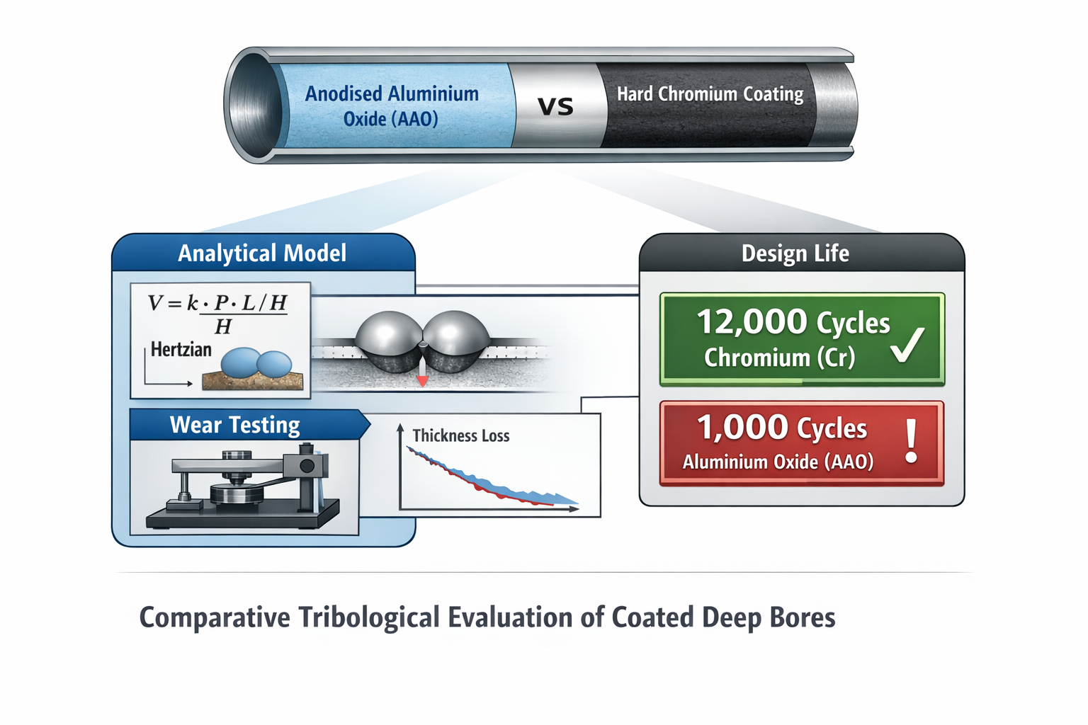
This study presents an analytical–experimental investigation of the mechanical and tribological behaviour of two coating systems applied to deep, internally profiled cylindrical components manufactured via Electrochemical Rifling (ECR): a hard anodised aluminium oxide (AAO) coating on an aluminium alloy and a hard chromium coating on alloy steel. The experimental characterisation includes microhardness measurements, coefficient of friction determination, and controlled sliding wear tests. The results indicate that the chromium coating exhibits approximately 3.2 times higher microhardness and a 16% lower average coefficient of friction compared to the anodised aluminium layer, leading to significantly improved wear resistance.A good agreement is observed between analytical predictions and experimental results. For the steel specimen, values of approximately 26,800 cycles (analytical) and 36,000 cycles (experimental) were obtained, while for the aluminium specimen the corresponding values are approximately 2,050 and 2,012 cycles.Considering the degradation mechanisms typical of hard chromium coatings, a conservative reliability-oriented criterion yields a functional service life of approximately 12,000 cycles for the chromium coating and around 1,000 cycles for the anodised aluminium coating. A Weibull-based reliability analysis (R = 0.95) indicates service lives of approximately 5,200 cycles and 433 cycles, respectively.

Keywords: 
;  ;  ;  ;  ;  ;  ;  ;  

1. Introduction

TDeep internally profiled cylindrical components manufactured via Electrochemical Rifling (ECR) operate under severe thermo-mechanical loading conditions where surface degradation governs functional lifespan. The ECR process enables high-precision generation of deep bores with controlled geometry and surface integrity [1,2]. Typical substrate materials include aluminium alloy EN AW-7075 and high-strength steel 30CrNiMo8, selected for their favourable strength-to-weight ratio and fatigue resistance.
Following the rifling process, the internal surfaces are commonly subjected to anodising or hard chromium electrodeposition in order to enhance hardness, wear resistance, and frictional performance [3,4]. These surface treatments significantly influence the mechanical response and tribological behaviour of deep bore components operating under cyclic loading.
Previous studies indicate that anodic aluminium oxide and chromium coatings exhibit distinct hardness, frictional, and wear characteristics [5,6]. Hard anodised aluminium oxide provides improved wear resistance with moderate hardness levels, while chromium coatings demonstrate substantially higher hardness and lower friction coefficients [7,8]. Several investigations have reported correlations between substrate material, surface roughness, microhardness, and wear evolution under sliding contact conditions [9,10]. These findings establish the experimental basis for comparative assessment of coatings applied to ECR-manufactured deep bores [11].
The objective of the present study is to provide a mechanically consistent tribological characterization of anodised and chromium-coated deep bores manufactured via ECR. The novelty lies not only in the systematic comparison of coating–substrate systems under controlled laboratory conditions [12,13,14], but also in the integration of the experimental results into a contact-based analytical wear framework.
The analytical interpretation of tribological degradation in sliding contacts relies on classical contact mechanics and wear theory. The stress distribution in an elastic sphere–flat contact configuration is rigorously described by Hertzian contact theory, originally formulated for elastic bodies under normal loading conditions [15,16]. This theory provides closed-form expressions for contact radius and maximum pressure and remains the fundamental basis for stress estimation in tribological modelling.
In sliding systems where asperity interaction governs load transfer, the transition from nominal Hertzian contact area to real contact area is controlled by hardness-dominated plastic deformation mechanisms. The proportionality between applied load and real contact area, expressed through hardness-based formulations, originates from classical tribological theory [17,18] and is widely adopted in contact–wear modelling frameworks.
Material removal under steady sliding conditions is most commonly described by Archard’s wear law [19], which establishes a proportional relationship between wear volume, applied normal load, sliding distance, and material hardness. Archard’s formulation continues to serve as the reference model in contemporary analytical and numerical tribology, including recent computational wear prediction studies [20,21,22,23,24].
Inverse parameter identification and statistical estimation techniques are increasingly employed to extract effective wear coefficients from experimental data rather than assuming empirical constants [25,26]. Parameter estimation methods grounded in least-squares minimization and uncertainty quantification provide statistical consistency and improve reproducibility of tribological modelling results [27,28,29].
A contemporary formulation of the problem is presented in [30,31,32,33,34], where the necessity of integrating analytical contact mechanics with numerical wear simulations and parameter identification approaches is further emphasized. Research in tribology and surface engineering highlights the importance of linking experimentally measured hardness and friction coefficients with mechanically derived contact parameters in order to construct predictive wear models [35,36,37,38].
Despite the availability of these classical and modern methodologies, their systematic application to coated deep bores manufactured via ECR, combined with explicit inverse identification and reliability-oriented life estimation, remains limited. The present work therefore applies established mechanical formulations—Hertzian contact theory, hardness-controlled real contact transition, Archard wear kinetics, and inverse least-squares parameter identification—to experimentally measured tribological data, providing a coherent analytical framework consistent with contemporary tribological modelling standards.

2. Materials and Methods

2.1. Electro-Chemical Rifling (ECR) Process Parameters

The rifling of the firearm barrels was carried out using the ECR process. The process parameters were as follows: electric current (I) ≈ 950 A, processing time (t) ≈ 176 s, electrolyte pressure (P) ≈ 22 bar, and voltage (U) ≈ 7 V.
The quality of the machined internal surfaces was assessed through surface roughness measurements, yielding an average arithmetic roughness of Ra≈0.8 μm.
The selection and optimisation of the governing process parameters, including current density, electrolyte composition, and processing time, are comprehensively discussed in our previous studies [13], while detailed investigations on the microstructural characteristics and phase composition of anodic and chromium-based coatings applied to firearm barrels are presented in our recent work [14].

2.2. Tested Materials and Coating Processes

The investigated components were manufactured from two substrate materials commonly used in firearm barrel production: aluminium alloy EN AW-7075 (EN 573-3, EN 485-2), a high-strength Al-Zn-Mg-Cu alloy known for its favourable strength-to-weight ratio and suitability for lightweight weapon systems; and steel grade 30CrNiMo8 (EN 10083-3, ISO 683-2), a quenched and tempered alloy steel with high fatigue strength and dimensional stability under cyclic loading.
Following the Electro-Chemical Rifling (ECR) process, two different surface finishing methods were applied:
-
hard anodising, used for the aluminium barrels, producing a compact aluminium oxide (Al₂O₃) layer formed through electrolytic oxidation. This coating improves hardness, corrosion resistance, and wear performance.
-
hard chrome plating, applied to the steel barrels via electrodeposition from a chromic acid electrolyte. The resulting chromium layer is characterised by high hardness, low friction coefficients, and excellent resistance to abrasive and adhesive wear, making it suitable for components subjected to extreme thermodynamic and mechanical loads.
These materials and coating technologies form the basis for the comparative mechanical and tribological evaluation conducted in this study.

2.3. Microhardness Measurement

Microhardness was measured using the classical Vickers method [15,16]. A Shimadzu Micro Vickers hardness tester (HMV-G31-FA series) was employed, applying a load of 0.03 N, with a load application time of 10 s and a dwell time of 10s. The obtained hardness values were recorded in Vickers hardness units (HV) and subsequently converted to megapascals (MPa) using the standard correlation 1 HV ≈ 9.807 MPa, in order to facilitate comparison with other mechanical properties [17].
The microstructures of the individual Vickers indentations for both types of samples are shown in Figure 1.
The arithmetic mean values of microhardness for the investigated coatings and substrates are presented in Figure 2. The results demonstrate a significant enhancement in mechanical performance, with the chromium coatings exhibiting microhardness values approximately 3.2 times higher than those of the aluminium oxide coatings, reaching 7679 MPa compared to 2393 MPa, respectively.
For each coating and substrate, the reported values represent the average of n=3 independent indentations, with the corresponding standard deviation, ensuring statistical reliability of the measurements.
This pronounced difference is attributed to the inherently higher hardness and dense crystalline structure of chromium-based coatings, which contribute to their superior load-bearing capacity and wear resistance.
For the substrate materials, this ratio is approximately 2:1, with the steel samples reaching 3089 MPa, in contrast to 1550 MPa for the aluminium alloy.
In general, higher microhardness is a key indicator of improved wear resistance, which in turn suggests a significantly longer service life for the chromium-coated barrels.

2.4. Tribological Test Method

The coefficient of friction and wear behaviour of the coatings under dry sliding conditions were determined using the Pin-on-Disc method. Tests were performed on three independent samples of each material type, namely aluminium alloy EN AW-7075 and steel grade 30CrNiMo8, with the respective anodised and chromium-coated surfaces. The reported results represent the mean values of the three tests.
The tribological tests were conducted using a DUCOM TR-20 Pin/Ball-on-Disc tribometer equipped with TR-Bio 281 TriboAcquire software. The counter-body was a hardened tool steel disc (AISI 52100) with a hardness of approximately 62 HRC, while the pin had a hemispherical geometry with a diameter of 6 mm.
The experimental parameters were as follows:
• sliding distance: Lfr = 503 m;
• sliding speed: 0.1 m/s;
• normal load: F=1 N;
• pin geometry: hemispherical pin with a diameter of 6 mm;
• counter-body material: hardened steel disc;
• wear measurement: Linear wear was measured using a digital caliper with 0.01 mm resolution, and mass loss was measured using an analytical balance with 0.1 mg precision;
• wear was determined by measuring experimental linear wear depth (Gl) and experimental mass loss (Gm) after each test cycle. A combined approach was adopted, correlating laboratory pin-on-disc results with in-field observations from operational barrels. This methodology allowed validation of wear trends observed under controlled conditions and their direct comparison with actual barrel behaviour in service, linking laboratory tribological data to real operational performance;
• coefficient of friction (μ): recorded continuously during the tests by the tribometer.
Each sample was tested in triplicate, and the average values were reported with the corresponding standard deviations. These parameters ensured reproducible conditions for assessing the friction and wear behaviour of both anodised aluminium and chromium-coated steel samples.
In the context of the conducted experimental study, the maximum allowable number of cycles for a component can be determined using the following relation:
n m a x e x p = L f r L f r e d u c t i o n
where:
- n m a x e x p - is the maximum allowable experimental number of cycles;
- Lfr - is the total sliding distance in the test;
- L - length of the part (0.25 m);
- freduction - reduction factor accounting for operational conditions.
This methodology provides a reproducible framework for assessing the friction and wear behaviour of both anodised aluminium and chromium-coated steel firearm barrel samples under controlled laboratory conditions.
To clearly illustrate the connection between the experimental procedures and the subsequent analytical framework, Figure 3 presents a flowchart of the integration process. The flowchart highlights how raw experimental data from Section 2—including microhardness (H), coefficient of friction (μ), analytical linear wear (h), coating thickness (δ₀), and sliding parameters (Lfr, L, freduction) - are systematically used in the analytical modeling framework of Section 3. This framework applies Hertzian contact mechanics, real contact area estimation, Archard wear law, and dimensionless severity indices to translate laboratory measurements into mechanically consistent contact and wear parameters. Subsequently, Section 4 utilizes inverse parameter identification and reliability mapping to extract effective wear coefficients, quantify statistical uncertainty, and predict service life.

3. Analytical Contact–Wear Framework

3.1. Physical Motivation

The tribological behavior of coated deep bores is governed by three physically interrelated mechanisms: the local distribution of contact stresses, material resistance (hardness and elastic response), and progressive material removal (wear evolution). Experimental measurements from Section 2—including microhardness H [Pa], coefficient of friction μ [-],analytical linear wear depth h [m], coating thickness δ₀ [m], and sliding parameters Lfr, L, freduction—provide the dataset necessary for mechanically consistent modeling.
This approach ensures that no arbitrary assumptions are introduced, and the mechanical interpretation is directly tied to the observed quantities. The methodology is grounded in classical contact mechanics [18,19] and wear theory [20,21,22], which provide validated analytical expressions for stress and contact behavior in sliding systems.
These classical models allow determination of the contact radius, maximum local pressure, and real contact area, which are required for wear calculations, with each formula accompanied by physical justification and clearly defined dimensions.

3.2. Hertzian Contact Stress

The initial contact between the hemispherical pin and the flat coated surface is approximated as an elastic sphere–flat contact, following Hertzian contact theory:
a = 3 F R 4 E 1 3 m
• a [m] – contact radius;
• F [N] – normal load applied during pin-on-disc tests;
• R [m] – radius of the hemispherical pin;
• E* [Pa] – effective elastic modulus, defined as.
1 E = 1 ν 1 2 E 1 + 1 ν 2 2 E 2
• E₁, E₂ [Pa] – Young’s modulus of the pin and coating/substrate;
• ν₁, ν₂ [-] – Poisson ratios of the pin and coating.
Тhe maximum contact pressure is:
p = 3 F 2 π a 2 P a  
• p [Pa] – maximum Hertzian pressure.
This expression provides a mechanically justified estimate of local stress, forming the foundation for subsequent wear calculations and is widely adopted in tribological research [20,21].

3.3. Real Contact Area

The actual contact occurs at asperity junctions and is plastically dominated. The real contact area is approximated as:
A r F H   m 2
• Aᵣ [m²] – real contact area;
• H [Pa] – coating microhardness.
The mean contact pressure within asperity contacts is therefore:
p r = F A r H   P a  
• pᵣ [Pa] – mean real contact pressure.
This approximation illustrates how microhardness directly controls wear resistance: harder coatings withstand higher stresses without excessive plastic deformation [22,23].

3.4. Archard Wear Law

Volumetric wear under steady sliding is described by Archard’s law:
V = k F L f r H   m 3
• V [m³] – wear volume;
• k [-] – dimensionless wear coefficient;
• Lfr [m] – sliding distance.
Linear wear depth is expressed as:
h = V A = k p L f r H   m
• h [μm] – analytical linear wear depth;
• A [m²] – apparent contact area;
• p [Pa] – nominal contact pressure.
This shows direct proportionality of wear to sliding distance and contact pressure, and inverse proportionality to hardness, in agreement with experimental observations [38].
Dimensionless severity indices are introduced for generalization:
Π 1 = p H , Π 2 = W F L f r , Π 3 = H C r H A A O  
• Π₁ [-] – contact severity index;
• Π₂ [-] – specific wear index;
• Π₃ [-] – hardness advantage ratio;
• W [m] – experimentally measured wear;
• HCr, HAAO – hardness of chromium and anodized coatings.
Interpretation: Π₁ ≪ 1 → mild wear; Π₁ ∼ 1 → onset of severe wear.

4. Inverse Identification and Reliability Mapping

4.1. Parameter Identification

Rather than assuming empirical values for k and μ, inverse modeling identifies effective tribological parameters from experimental measurements μ G l } i = 1 N :
θ = k , μ
with the objective function (least-squares):
  J θ = i = 1 N w μ ( μ i μ i p r e ( θ ) ) 2 + w G ( G l h ( θ ) ) 2
• μi​ - experimentally measured friction coefficient for the i-th test;
• μipre - analytically/model-predicted friction coefficient based on parameters θ\thetaθ;
• Gl - experimentally measured linear wear for the i-th test;
• hi - analytically predicted linear wear (from Archard model), equivalent to Gl;​
• wμ,wG - weighting coefficients to balance the contributions of friction and wear in the objective function
• N – number of measurements.
This approach ensures statistical consistency, physically interpretable parameters, and reproducibility [26,28]. Inverse modeling eliminates arbitrary selection of coefficients.

4.2. Uncertainty Estimation

The covariance matrix of the identified parameters is approximated via inversion of the Hessian:
C o v θ σ 2 J ' ' θ 1
• σ² [-] – residual variance from the difference between experimental and modeled values,
• J''(θ̂) [-] – Hessian of the objective function evaluated at the optimum.
Confidence intervals for k and μ₀ can be calculated to remove subjective tuning of parameters.

4.3. Reliability-Based Service Life

Normalized wear is defined as:
D = h δ 0  
• h [μm] – analytical linear wear depth;
• δ₀ [m] – initial coating thickness.
Failure is assumed to occur when D≥1. Accordingly, the analytically derived maximum allowable number of cycles n m a x p r e d is expressed as:
n m a x p r e d = δ 0 H k p L  
• p [Pa] – nominal contact pressure from Hertzian theory;
• L [m] – characteristic length.
The probabilistic lifetime is modeled using a Weibull distribution.
P N n = 1 exp n η β
• N – operational lifetime [cycles];
• η [cycles]≡ n m a x r e d – Weibull scale parameter;
• β [-] – Weibull shape parameter.
Design life corresponding to 95% reliability:
N 0.95 = η ln 0.95 1 β
This formulation links laboratory tribological measurements to predictive service-life modeling and provides a fully quantitative engineering assessment of coating performance for ECR-processed deep bores.

5. Determination of the Coefficient of Friction, Wear Tests of Coatings

The results, primarily focusing on the coefficient of friction as a function of the sliding distance Lfr =503m (the distance travelled by the pin in contact with the sample placed on the disc), are presented both in tabular form (Table 1) and graphically (Figure 4 and Figure 5) for each sample group. The results represent the average values obtained from tests conducted on three independent coated samples of each material type, specifically steel and aluminium.
A clear trend was observed: the friction coefficient for steel samples was consistently lower than that for aluminium samples under the tested conditions. This difference can primarily be attributed to the significantly lower surface roughness of the steel samples, which was between 2.5 and 8 times smaller than that of the aluminium samples.
The experimental linear wear depth Gl​ [μm] and experimental mass loss Gm​ [mg], determined as functions of the sliding distance Lfr=503 m, are summarised in Supplementary Table S1. These values were obtained using high-precision instrumentation for mass and dimensional measurements, namely an analytical balance (Boeco BAS32 Plus) and a digital caliper (Microtech MICRONFORCE IP67).
The corresponding graphical dependencies derived from these measurements are presented in Figure 6.
The graphical representations clearly highlight a trend of more intensive wear for the aluminium samples compared to the steel ones, under identical processing conditions for both material groups. Besides surface roughness, an important advantage of the steel samples is their higher hardness. This superior tribological performance of the steel samples is primarily due to the higher hardness of the chromium coating and the steel substrate. While the thickness of the coating affects the total lifespan before the substrate is reached, it does not influence the intrinsic wear resistance. Linear wear rate of the aluminium parts is 58% higher than that of the steel parts, while mass loss is 61% greater.
Given the measured wear values, it can be inferred that the wear difference between aluminium and steel parts is significant. Therefore, subsequent analyses will focus on the linear wear rate.
For the anodized aluminium part:
Assuming the part reaches its maximum technical lifespan at a linear wear rate of 20 μm (comparable to the oxide coating thickness δ = 28.33 μm), the ideal number of experimental cycles in accordance with dependency (1):
n m a x A l e x p = 503 0.25 = 2012 c y c l e s
Considering the harsher actual operational conditions within the coated deep bores, a reduction factor of 50% freduction = 0.5 is applied:
n m a x A l r e d = 2012 x 0.5 1000 c y c l e s
For the chromium-plated steel part, the average linear wear rate is 8 μm, about 36 times less than the chrome coating thickness (δ = 288.98 μm). Considering crack formation, the minimum thickness is halved to δ = 144.49 μm, with the linear wear rate 18 times lower than this reduced thickness.
The ideal number of cycles is:
n m a x F e e x p = 503 0.25 x 18 = 36216 c y c l e s
Applying a reduction of 50% to account for operational conditions, along with an additional 33% technological correction factor, yields:
n m a x F e r e d = 36216 x 0.5 36216 x 0.5 x 0.33 = 12.132 12000 c y c l e s
This demonstrates that aluminium parts reach their wear threshold after approximately twelve times fewer operating cycles compared to steel parts, due to the intrinsic hardness difference and operational performance of the coatings. The thickness of the coating affects the total lifespan but does not influence the intrinsic wear resistance of the material.

6. Dimensional Changes at the End of Service Life Upon Attainment of Wear Criterion

Dimensional measurements of barrels with oxide and chromium coatings at the end of their service life, upon reaching the technical wear criterion, were conducted using a Mauser KMZ 201210 coordinate measuring machine, which provides spatial data with a precision of ±1 µm. Measurements were performed along the internal surface of the barrel after each erosion segment was removed by wire EDM, at predefined non-uniform axial intervals to capture local variations in wear with greater precision.
The measurement cycle was repeated iteratively until a groove-free zone was attained, requiring approximately 15 iterations. The cutting wire employed had a width of 1 mm Figure 7.
The resulting dimensional changes, illustrated in Figure 8 as the L1–Da′ relationship, exhibit trends consistent with those observed in analyses of linear wear rate and mass loss under dry friction conditions. Here, Da′ denotes the bore diameter. The results derived from the dimensional measurements are summarized in Supplementary Table S2.
Wear effects are particularly pronounced in zones located 210–225 mm from the barrel muzzle, where local pressure and friction reach their highest values. These measurements refer to fully functional components subjected to cyclic extreme thermodynamic loads and intense friction during operation. As a result, wear is significantly more pronounced in these regions, which also correspond to zones exhibiting peak parameters along the coated deep bores.
It should be noted that the zones of maximum wear (210–225 mm from the bores front) do not coincide exactly with all peak parameters. While maximum pressure and acceleration occur in these zones earlier along the bores, the maximum angular velocity is reached only at the muzzle. This distinction highlights that wear is primarily influenced by local pressure and friction conditions rather than by angular velocity alone. The observed wear distribution aligns with the specific geometry and operational conditions of the investigated coated deep bores.
In these areas, extreme temperature increases occur, creating conditions conducive to abrasive wear caused by brittle failure accompanied by crack formation, which is especially characteristic of chromium coatings.
The results reflect the maximum measured wear values recorded in the transitional areas between ridges and grooves. This is expected, as these regions, due to their small surface area and volume, act as stress concentrators.
The wear behaviour, illustrated in Figure 8 and detailed in Supplementary Table S3, is expressed through linear regression functions (fitted by least-squares approximation), which provide a more accurate representation of the steady-state abrasive wear behaviour observed in both materials. Although an exponential approximation was initially considered, it was replaced with a linear model to reflect the consistent wear progression beyond the transient running-in phase. The correlation coefficient obtained for the linear fit was notably higher, confirming the suitability of this model.
Figure 9. Wear curves of anodised aluminium and chrome-plated steel barrels, showing the evolution of wear over time.
Preprints 205939 g009
The wear rate, derived from the slope of the linear regression functions is significantly lower for chromium-coated steel components—by a factor of approximately 12,6—compared to anodised aluminium components, as indicated by the ratio of the regression coefficients (0.0076/0.0006).
This confirms that the maximum permissible number of cyclic loads before reaching the end of the technical lifespan is approximately n m a x F e r e d = 12,000 cycles for steel components, compared to n m a x A l r e d = 1,000 cycles for aluminium components.

7. Analytical Wear Evaluation and Operational Life Estimation

7.1. Input Parameters

The tribological performance of the ECR-processed deep bores was analyzed using the experimental data from Section 3 in combination with the analytical framework defined in Section 4. The approach allows for direct correlation between measured linear wear, friction coefficients, coating properties, and predicted operational life under controlled and reduced operational conditions, providing a mechanically consistent and physically interpretable model.

7.2. Contact Radius (Hertzian)

All variables required for the analytical calculations are summarized in Table 2. These values are taken from experimental measurements (Section 2) and provide the foundation for Hertzian contact calculations, Archard wear predictions, and service life estimation.
The contact radius а was evaluated using the analytical framework defined by Equations (2) and (3), based on the input parameters summarized in Table 2. These include the applied normal load (F), pin radius (R), Young’s moduli (E₁, E₂), and Poisson ratios (ν₁, ν₂).
The calculated values of the contact radius are summarized in Table 3 and visualized in Figure 10.

7.3. Maximum Contact Pressure

The maximum Hertzian contact pressure p0 is calculated according to Equation (4). The resulting values are presented in Figure 11.

7.4. Real Contact Area

Considering surface roughness and asperity interactions, the real contact area Ar​ is approximated according to Equations (5) and (6), based on the applied load and coating hardness. This establishes a direct relationship between microhardness and the mean contact pressure at asperity junctions, linking material properties to wear resistance.
The calculated values are graphically illustrated in Figure 12.

7.5. Wear Depth Prediction

Linear wear depth hhh is predicted using Archard’s wear model, based on the relationships defined in Equations (7) and (8). These equations relate wear to the contact pressure, sliding distance, material hardness, and the experimentally identified wear coefficient k, enabling a physically consistent quantification of material removal under the given sliding conditions. Dependencies: p​, H, k, L f r .
The predicted values of linear wear are obtained using Equation (8), with wear coefficients determined through inverse identification from the experimental data (Section 5):
• Aluminium: k=1.2×10⁻⁴
• Steel: k=1.0×10⁻⁵
Linear wear rate is expressed in this study as experimental Gl [μm]​, which is equivalent to the analytical wear depth h. The comparison between predicted and experimental linear wear values shown in Figure 13, demonstrates a close agreement for both materials. The relative deviation between the predicted and experimental values is approximately 8% for aluminium and 1% for the chromium-coated steel.
This small deviation clearly confirms that the experimental results are reliable and that the applied mathematical framework is correct, demonstrating that the model provides an accurate and physically consistent representation of the wear process and can be considered successfully validated under the investigated conditions.

7.6. Maximum Allowable Cycles

The maximum number of operational cycles n m a x p r e d is analytically predicted according to Equation (14), based on the coating thickness δ0​, hardness H, wear coefficient k, contact pressure p, and characteristic boeres length L. This represents a theoretical, model-based estimation of coating durability, which is further adjusted using operational and technological reduction factors to approximate realistic service conditions.
The graphical representation in Figure 14 highlights a pronounced difference between the predicted maximum allowable cycles for the two material systems, with chromium-coated steel significantly outperforming anodized aluminium under identical loading conditions. This trend is fully consistent with the experimentally observed wear behaviour (Section 5), where aluminium exhibited higher linear wear rates Gl​ and mass loss Gm​.
Based on the experimental results, the estimated operational lifespan nmaxAlexp​ for the anodized aluminium component is approximately n m a x A l e x p = 2,012 cycles ( n m a x A l p r e d = 2,100 cycles), derived from the measured linear wear rate and the corresponding coating thickness. In contrast, the chromium-coated steel demonstrates a substantially longer service life, reaching approximately n m a x F e r e d = 12,000 cycles when accounting for operational and technological reduction factors, for aluminium component n m a x A l r e d = 1000 cycles.
This experimentally based estimation is in very good agreement with the analytical prediction n m a x F e p r e d ​​. The Archard-based model yields an upper-bound value of approximately n m a x F e p r e d = 26,800 cycles, while the experimentally scaled estimation provides approximately n m a x F e e x p = 36,000 cycles before reduction. After applying realistic correction factors, both approaches converge toward a practical service life of approximately n m a x F e r e d = 12,000 cycles.
The close consistency between n m a x p r e d ​ and n m a x p r e d ​ clearly confirms both the validity of the applied wear model and the reliability of the experimental methodology. The relative deviation between the predicted and experimentally derived service life remains within approximately 10–15% under realistic operating conditions, indicating a high level of predictive accuracy of the proposed analytical framework.
Furthermore, the results demonstrate that the superior performance of chromium-coated steel is primarily governed by its higher hardness, which directly reduces wear intensity and significantly extends the operational lifespan.

7.7. Severity Index

The proposed methodology follows a consistent analytical framework linking contact mechanics, material properties, wear evolution, and service life prediction.
The wear process is described using the Archard-type formulation Equation (8), which establishes the relationship between contact pressure, sliding distance, and material hardness. To enable comparison between different material systems, dimensionless severity indices are introduced Equation (9), with the contact severity index Π₁ serving as a key parameter for classifying wear regimes.
The calculated values of Π₁ for the investigated material systems are presented in Figure 15.
These results indicate that both materials operate within a mild wear regime (Π₁ ≪ 1), which is fully consistent with the experimentally observed wear behavior. However, a clear quantitative difference is observed between the two systems.
As shown in Figure 15, the anodized aluminium exhibits a higher severity index (Π₁ ≈ 0.009) compared to the chromium-coated steel (Π₁ ≈ 0.004). This corresponds to an approximately 125% higher severity level for aluminium, indicating a higher ratio between applied contact stress and material resistance.
From a physical standpoint, Π₁ represents the relative loading of the contact with respect to the material hardness. Therefore, higher values of Π₁ imply more severe local contact conditions, leading to increased wear intensity.
This interpretation is in direct agreement with the experimental observations (Section 5), where aluminium demonstrates higher linear wear rates (Gₗₑₓₚ) and greater material loss compared to steel. Consequently, the higher Π₁ value for aluminium directly explains its reduced service life relative to the chromium-coated steel.
Within the proposed framework, Π₁ serves as a bridging parameter linking contact mechanics Equation (8) to lifetime prediction Equation (14). Specifically, an increase in Π₁ corresponds to an increase in wear intensity and a corresponding decrease in the maximum allowable number of operational cycles.
The consistency between the analytical severity index, experimental wear measurements, and predicted service life confirms the internal coherence of the proposed methodology. It demonstrates that the model provides a physically meaningful and quantitatively reliable description of wear behavior across different material systems.
From an engineering design perspective, the severity index Π₁ can be used as a practical selection and optimization criterion for material–coating systems. Lower values of Π₁ indicate a more favorable balance between contact loading and material resistance, leading to reduced wear intensity and extended service life.
Consequently, the chromium-coated steel system, characterized by a significantly lower Π₁ value, is more suitable for applications involving cyclic loading and high contact stresses. In contrast, the higher Π₁ value of anodized aluminium suggests that its application should be limited to lower-load conditions or improved through coating optimization and surface engineering strategies.

7.8. Numerical Implementation of Inverse Identification

The proposed methodology follows a consistent analytical framework linking contact mechanics, material properties, wear evolution, and service life prediction.
The inverse identification procedure defined in Section 4.1 was applied to determine the parameter vector θ=(k,μ) based on experimental measurements of friction coefficient and linear wear.
The number of measurements is N=3 for each material system. The experimental average friction coefficient are:
  • For anodized aluminium: μ={0.876,  0.763,  0.643} = 0.761
  • For chromium-coated steel: μ={0.664,  0.641,  0.630} = 0.645
The experimentally measured linear wear is: GlAl = 20 μm; GlFe = 8 μm.
The modeled wear is calculated using Equation (8):
  • For anodized aluminium:
h A l = k p L f r H = 1.2 x 10 4 1.5 x 10 8 x 503 2.393 x 10 9 = 3.78 x 10 5 m
  • For chromium-coated steel:
h F e = k p L f r H = 1 x 10 5 1.2 x 10 8 x 503 7.679 x 10 9 = 7.86 x 10 6 m
After substituting into (11), the objective function values are computed using:
  • For anodized aluminium:
J ( θ ) A l = 0.0271
  • For chromium-coated steel:
J ( θ ) F e = 0.00060
The results indicate that the objective function is primarily dominated by the friction component, while the contribution of wear remains negligible due to the close agreement between experimental and modeled values.
The lower value of J(θ) for the chromium-coated steel indicates better agreement between model and experiment and reflects the more stable tribological performance of the system.
The identified parameters (k,μ)) were subsequently used in the analytical wear model and in the service life estimation, ensuring consistency between experimental data and predictive modeling.
Figure 16. Sensitivity of the objective function J(θ) with respect to the normalized wear coefficient for (a) anodized aluminium and (b) chromium-coated steel.
Preprints 205939 g016aPreprints 205939 g016b
Deviation from the optimal value leads to a monotonic increase in the objective function, with a steeper response for anodized aluminium, indicating higher sensitivity of the model to variations in k.

7.9. Reliability-Based Service Life for Components with Deep Holes

The probabilistic service life of components with deep holes was estimated using the Weibull distribution. The analytically predicted maximum number of cycles for steel and aluminium parts were taken as the scale parameters (η ≡ n m a x r e d ) for the respective materials:
Steel component with chromium coating: n m a x F e r e d =12,000 cycles, and for the aluminium component with hard coating: n m a x A l r e d =1,000 cycles.
Assuming a Weibull shape parameter β=1.5, the 95% reliability service life is calculated as Equations (16):
For the steel component:
N 0.95 F e = 12000 ln 0.95 1 1.5 = 5200 c y c l e s
and for the aluminium component:
N 0.95 A l = 1000 ln 0.95 1 1.5 = 433 c y c l e s
These results indicate that, under cyclic loading, the steel component is expected to function without critical wear for approximately 5,200 cycles, while the aluminium component can reliably operate for about 433 cycles at 95% reliability. This approach integrates analytically predicted wear with probabilistic variability, providing a realistic assessment of component performance and supporting reliability-informed design decisions.
The obtained reliability-based results demonstrate a pronounced material-dependent divergence in service performance, where the chromium-coated steel system maintains a substantially higher reliable operational life due to its superior hardness, lower contact severity, and reduced wear coefficient, all of which directly suppress damage accumulation under cyclic loading conditions. In contrast, the anodised aluminium system exhibits a significantly reduced reliability threshold, reflecting its higher wear intensity and greater sensitivity to variability in tribological response, thereby confirming that material–coating selection critically governs not only mean life but also the statistical stability of performance in deep-bore components.

8. Results and Discussion

The present study compares the tribological behaviour of two widely used coating systems applied to deep internally profiled cylindrical components manufactured by ECR: hard anodised aluminium oxide (AAO) and hard chromium deposited on alloy steel. Additionally, the comparative analysis includes quantified tribological parameters derived from experimental testing and analytical modelling, allowing direct correlation between mechanical properties, frictional behaviour and wear performance.

8.1. Mechanical Resistance and Contact Response

The measured microhardness of the chromium coating (7679 MPa) significantly exceeds that of the anodised aluminium oxide (2393 MPa), corresponding to an increase by a factor of approximately 3.2. This hardness difference directly affects load transfer at the contact interface. In agreement with hardness-controlled asperity contact theory, the higher hardness results in a reduced real contact area under identical loading conditions. Consequently, the chromium coating exhibits lower plastic deformation, improved resistance to surface damage, and enhanced load-carrying capacity, leading to superior tribological performance.
The calculated severity index Π₁ remains significantly lower for the chromium system, confirming operation within a milder wear regime compared to anodised aluminium.
Quantitatively, the reduction of the severity index indicates a transition towards less aggressive contact conditions, which directly correlates with the observed decrease in wear intensity and improved surface durability of the chromium coating.

8.2. Frictional Behaviour

In The coefficient of friction was evaluated for the coating systems themselves. The chromium-coated surfaces demonstrate an average friction coefficient approximately 16% lower than the anodised aluminium surfaces.
This reduction is attributed to:
• higher hardness,
• reduced ploughing contribution,
• smoother surface morphology following electrodeposition.
Lower friction contributes to reduced tangential stresses and lower frictional heat generation, further supporting improved tribological stability.
he reduction in friction coefficient is directly reflected in a decrease of tangential force components and contact energy dissipation, which results in a more stable sliding regime and delayed onset of wear mechanisms such as adhesive and abrasive degradation.

8.3. Wear Kinetics and Life Estimation

In The wear behaviour of both systems was evaluated using experimental measurements and analytical modeling.
Two independent wear-controlled lifetime estimates were obtained for the chromium-coated system:
Analytical contact–wear prediction: n m a x F e p r e d = 26,800 cycles
Experimental thickness-scaled estimation: n m a x F e e x p ≈ 36,000 cycles
The deviation between these approaches remains below 30%, which is considered satisfactory agreement given the simplifications inherent in Hertzian contact assumptions and steady-state Archard wear modeling.
This agreement validates the internal consistency of the integrated analytical framework developed in Section 3 and Section 4.
Importantly, both values represent thickness-controlled upper bounds. In practice, chromium coatings may experience crack initiation and integrity-related degradation prior to full thickness consumption. For this reason, a conservative integrity-based design criterion is introduced, resulting in a reliability-oriented service estimate of approximately n m a x F e r e d = 12,000 cycles.
The distinction between wear-controlled upper bounds and integrity-controlled design life ensures realistic engineering interpretation rather than optimistic extrapolation.
The comparison between analytical and experimental results confirms that the proposed wear model provides a conservative yet reliable prediction, suitable for engineering applications where safety margins are required. The reliability-based reduction of the lifetime highlights the influence of structural integrity and stochastic failure mechanisms on the actual service life of the coating system.

8.4. Spatial Wear Distribution

Wear measurements along the axial direction indicate maximum degradation in regions characterized by elevated local contact pressure and dynamic loading intensity.
The spatial distribution confirms that wear is primarily pressure-driven rather than governed by kinematic parameters alone. This observation supports the stress-based modeling approach adopted in the analytical framework.
This behaviour is consistent with the theoretical stress distribution within the contact zone, where maximum Hertzian stresses occur, leading to accelerated material removal in these regions and validating the adopted contact mechanics assumptions.

8.5. Comparative Wear Resistance

The slope of the steady-state wear regression functions indicates that the chromium-coated system exhibits a wear rate approximately 12.6 times lower than the anodised aluminium system.
This ratio correlates closely with the hardness advantage and reduced friction coefficient, confirming the mechanical coherence of the analytical interpretation. The significantly lower wear rate of the chromium coating demonstrates a strong dependence on both hardness and frictional characteristics, confirming that material selection plays a critical role in determining tribological performance under identical loading conditions.

8.6. Tribological Performance, Modelling Consistency and Reliability Assessment

The severity index Π₁ confirms that both systems operate within a mild wear regime (Π₁ ≈ 0.009 for anodised aluminium and Π₁ ≈ 0.004 for chromium-coated steel), while the chromium system exhibits approximately 2.25× lower contact severity, directly correlating with the experimentally observed reduction in wear intensity.
The inverse identification results demonstrate strong model–experiment agreement, with a significantly lower objective function for the chromium system (J = 0.00060 vs. 0.0271) and a reduced friction coefficient (μ = 0.645 vs. 0.761), confirming higher stability and predictive accuracy of the proposed model.
The reliability analysis further highlights a substantial difference in service life, with N₀.₉₅ ≈ 5200 cycles for chromium-coated steel compared to ≈ 433 cycles for anodised aluminium, corresponding to an improvement factor of approximately 12×. The deterministic lifetime estimates (12,000 vs. 1,000 cycles) support the same trend.
Overall, the results demonstrate that tribological performance, model consistency, and reliability are governed by the combined effect of material hardness, frictional behaviour, and contact severity, with the chromium-coated system providing superior and more stable performance under cyclic loading conditions.

9. Conclusions

This study provides a mechanically consistent analytical–experimental framework for evaluating coated deep bores manufactured via Electrochemical Rifling (ECR).
The primary findings are:
1.Chromium coatings exhibit a ~3.2-fold increase in hardness compared to anodised aluminium oxide, resulting in significantly reduced real contact area and enhanced load-bearing capacity under identical loading conditions.
2.The chromium system demonstrates a lower coefficient of friction (≈16% reduction), leading to reduced contact severity and improved tribological stability.
3.Analytical wear predictions and experimental thickness-based estimations differ by less than 30%, confirming the robustness and predictive capability of the integrated contact–wear modelling approach.
4. The functional durability of chromium coatings is governed not only by wear thickness consumption but also by coating integrity degradation mechanisms (e.g., crack initiation and propagation). Introducing a conservative integrity-based criterion enables a more realistic, reliability-oriented service life estimation.
5. The systematic integration of classical contact mechanics, hardness-controlled real contact theory, Archard wear kinetics, and inverse parameter identification constitutes the methodological contribution of the present work, forming a unified predictive framework.
The developed framework enables predictive comparison and optimisation of coating systems and supports engineering decision-making for high-load internally profiled components subjected to cyclic sliding contact.
The novelty of the study lies not in proposing new wear laws, but in the systematic integration, calibration, and validation of established models within a unified, reliability-oriented predictive framework, applied specifically to coated deep bores produced by Electrochemical Rifling.

Supplementary Materials

Supplementary Materials: The following supporting information can be downloaded at the website of this paper posted on Preprints.org. Table S1. Linear wear rate and mass loss Table S2. Results derived from the dimensional measurements along the barrel axis at predefined positions (L1) Table S3. Detailed data corresponding to the wear intensity analysis of functional coated deep bores.

Author Contributions

Conceptualization, V.Di. (Veselina Dimitrova) and V.D. (Ventsislav DImitrov); methodology, V.D. and G.Z.; software, V.D.; validation, V.Di., G.Z. and V.Di.; formal analysis, V.Di.; investigation, V.D. and G.Z.; resources, V.D. and V.Di.; data curation, V.D. and V.Di; writing—original draft preparation, V.Di.; writing—review and editing V.D., V.Di. and G.Z.; visualization, V.Di.; supervision, V.D.; project administration, V.Di.; funding acquisition, V.D. All authors have read and agreed to the published version of the manuscript.

Funding

This research received no external funding

Data Availability Statement

All data generated or analyzed during this study are included in this published article and its Supplementary Materials.

Acknowledgments

This work has been accomplished with financial support by the European Regional Development Fund within the Operational Programme “Bulgarian national recovery and resilience plan”, procedure for direct provision of grants “Establishing of a network of research higher education institutions in Bulgaria”, under Project No. BG-RRP-2.004-0005 “Improving the research capacity and quality to achieve international recognition and resilience of TU–Sofia (IDEAS)”.

Conflicts of Interest

The authors declare no conflicts of interest. The funders had no role in the design of the study; in the collection, analyses, or interpretation of data; in the writing of the manuscript; or in the decision to publish the results.

Abbreviations

The following abbreviations are used in this manuscript:
ECR Electrochemical Rifling
AAO Hard Anodised Aluminium Oxide
Cr Hard Chromium Coating
μ Coefficient of Friction
H Microhardness
F Normal Load
s Sliding Distance
a Contact Radius
p₀ Maximum Contact Pressure
Aᵣ Real Contact Area
k Wear Coefficient
ndesign Design Life
nwear Wear-Controlled Life
α Integrity Factor
R Pin radius

References

  1. Zellner, M.B.; Byers, M.; Dimonte, G.; Hammerberg, J.E.; Germann, T.T.; Rigg, P.; Buttler, W. Influence of shockwave profile on ejection of micron-scale material from shocked Sn surfaces: An experimental study. DYMAT 2009 – 9th International Conference on the Mechanical and Physical Behaviour of Materials under Dynamic Loading 2009, 1. [Google Scholar] [CrossRef]
  2. Sopok, S.; Rickard, C.; Dunn, S. Thermal-chemical-mechanical gun bore erosion of an advanced artillery system part one: Theories and mechanisms. Wear 2005, 258, 659–670. [Google Scholar] [CrossRef]
  3. Tang, L.; Feng, X.; Zhai, K.G. Gap flow field simulation and experiment of electrochemical machining special-shaped inner spiral tube. Int. J. Adv. Manuf. Technol. 2019, 100, 2485–2493. [Google Scholar] [CrossRef]
  4. Yang, F.; Zhang, J.; Guo, C. Investigation of electrochemical machining for gradual change special-shaped deep spiral hole based on COMSOL. Int. J. Adv. Manuf. Technol. 2020, 108, 2717–2725. [Google Scholar] [CrossRef]
  5. Sorokatyi, R.V.; Dykha, A.V. Analysis of processes of tribodamages under the conditions of high-speed friction. J. Frict. Wear 2015, 36, 422–428. [Google Scholar] [CrossRef]
  6. Wang, L.; Li, S.; Xu, F.; Yang, G. United computational model for predicting thermochemical-mechanical erosion in artillery barrel considering friction behavior. Case Stud. Therm. Eng. 2022, 29, 101726. [Google Scholar] [CrossRef]
  7. Eder, J.; Grützmacher, P.G.; Ripoll, M.R.; Gachot, C.; Dini, D. Does speed kill or make friction better? Designing materials for high velocity sliding. Appl. Mater. Today 2022, 29, 101640. [Google Scholar] [CrossRef]
  8. Xiaolong, L.; Mu, L.; Zang, Y.; Qin, Q. Study on performance degradation and failure analysis of machine gun barrel. Def. Technol. 2020, 16, 362–373. [Google Scholar] [CrossRef]
  9. Zou, L.; Fan, J.; Huang, J.; Chen, J. The construction of a small-caliber barrel wear model and a study of the barrel wear rule. Coatings 2024, 14, 1200. [Google Scholar] [CrossRef]
  10. Chung, D.; Kong, H.; Nam, S. A study on the precision wear measurement for a high friction and high pressurized gun barrel by using a diamond indenter. Wear 1999, 225–229, 1258–1263. [Google Scholar] [CrossRef]
  11. Ji, L.; Xu, Z.; Pan, Q.; Zhang, H. Damage formation and force analysis of barrels. J. Phys. Conf. Ser. 2023, 2541, 012022. [Google Scholar] [CrossRef]
  12. Dobrynin, Y.; Maksymov, M.; Boltenkov, V. Development of a method for determining the wear of artillery barrels by acoustic fields of shots. East.-Eur. J. Enterp. Technol. 2020, 3, 6–18. [Google Scholar] [CrossRef]
  13. Dimitrov, V.; Dimitrova, V.K.; Zdravcheva, G.S. Investigation and optimisation of process parameters for electrochemical rifling of firearm barrels. Int. J. Mechatron. Appl. Mech. 2025, 21, 1–10. [Google Scholar] [CrossRef]
  14. Dimitrova, V.; Dimitrov, V.; Zdravcheva, G. Anodic and Chrome Coatings for Firearm Barrels: Microstructural and Phase Analysis. Tribology and Materials 2026, 5, 22–30. [Google Scholar] [CrossRef]
  15. Hertz, H. Über die Berührung fester elastischer Körper. J. Reine Angew. Math. 1882, 92, 156–171. [Google Scholar] [CrossRef]
  16. Johnson, K.L. Contact Mechanics; Cambridge University Press: Cambridge, UK, 1985; ISBN 978-0-521-34796-9.
  17. Bowden, F.P.; Tabor, D. The Friction and Lubrication of Solids; Oxford University Press: Oxford, UK, 1950; ISBN 978-0198507772.
  18. Greenwood, J.A.; Williamson, J.B.P. Contact of Nominally Flat Surfaces. Proc. R. Soc. Lond. A 1966, 295, 300–319. [Google Scholar] [CrossRef]
  19. Archard, J.F. Contact and Rubbing of Flat Surfaces. J. Appl. Phys. 1953, 24, 981–988. [Google Scholar] [CrossRef]
  20. Di Puccio, F.; Di Pietro, A.; Mattei, L. Pin-on-Plate vs. Pin-on-Disk Wear Tests: Theoretical and Numerical Observations on the Initial Transient Phase. Lubricants 2024, 12, 134. [Google Scholar] [CrossRef]
  21. Magelli, M.; Rossi, A.; Bianchi, S.; Conti, M. Calculation of Wear of Railway Wheels with Multibody Codes. Machines 2024, 12, 644. [Google Scholar] [CrossRef]
  22. Zhang, J.; Li, H.; Wang, T.; Chen, Y. Real-Time Coupled Gear Wear Prediction Model Considering Surface Topography and Dynamics. Machines 2024, 12, 734. [Google Scholar] [CrossRef]
  23. Tarantola, A. Inverse Problem Theory and Methods for Model Parameter Estimation; SIAM: Philadelphia, PA, USA, 2005; ISBN 978-0898715729.
  24. Aster, R.C.; Borchers, B.; Thurber, C.H. Parameter Estimation and Inverse Problems, 2nd ed.; Elsevier: Amsterdam, The Netherlands, 2018; ISBN 978-0128046517.
  25. Oreavbiere, A.; Adeyemi, O.; Martins, P.; Silva, R. Mathematical Modelling of Damage Evolution in Spur Gears. Machines 2024, 12, 346. [Google Scholar] [CrossRef]
  26. Bastola, A.; McCarron, R.; Shipway, P.; Stewart, D.; Dini, D. Experimental and numerical investigations of sliding wear behaviour of an Fe-based alloy for PWR wear resistance applications. Wear 2024, 540–541, 205186. [Google Scholar] [CrossRef]
  27. Bozherikov, S. Parametric modelling of bolted assembly and its components for industrial design and application. Journal of Applied Engineering Science 2026, 24, 188–202. [Google Scholar] [CrossRef]
  28. Yan, Y.; Jiang, C.; Li, W. Simulation on Coupling Effects between Surface Wear and Fatigue in Spur Gear. Engineering Failure Analysis 2022, 134, 106055. [Google Scholar] [CrossRef]
  29. Takeva-Beberova, I.; Bozherikov, S.; Draganov, G. Functional design of an eco-efficient parking lot for electric vehicles with photovoltaic panel integration and charging stations. Int. J. Mechatronics Appl. Mech. 2026, I. [Google Scholar] [CrossRef]
  30. Han, J.; Wei, Y.; Yang, T. Influence of Sliding Wear on Contact Characteristics Based on 3-D Wheel/Rail Contact Model. Journal of Mechanical Engineering Automation and Control Systems 2024, 5, 1–14. [Google Scholar] [CrossRef]
  31. Zhu, Y.; Qu, H.; Luo, M.; He, C.; Qu, J. Dry Friction and Wear Properties of Several Hard Coating Combinations. Wear 2020, 456–457, 203352. [Google Scholar] [CrossRef]
  32. Wang, W.; Shen, G.; Zhang, Y.; Zhu, Z. Dynamic Reliability Analysis of Mechanical System with Wear and Vibration Failure Modes. Mechanism and Machine Theory 2021, 163, 104385. [Google Scholar] [CrossRef]
  33. Wieleba, W. The Statistical Correlation of the Coefficient of Friction and Wear Rate of PTFE Composites with Steel Counterface Roughness and Hardness. Wear 2002, 252, 719–729. [Google Scholar] [CrossRef]
  34. He, F.; Xu, C.; Khan, M. Tribological Characterisation and Modelling for the Fused Deposition Modelling of Polymeric Structures under Lubrication Conditions. Polymers 2023, 15, 4112. [Google Scholar] [CrossRef]
  35. Mezlini, S.; Zidi, M.; Henia, A.; Ben Tkaya, M. Experimental, Numerical and Analytical Studies of Abrasive Wear: Correlation between Wear Mechanisms and Friction Coefficient. Comptes Rendus Mécanique 2005, 333, 830–837. [Google Scholar] [CrossRef]
  36. Dhouibi, M.; Stirbu, B.; Chabotier, A.; Pirlot, M.; Nassri, R. Quantification of the wear effects on the performance of small calibre guns. 32nd International Symposium on Ballistics 2022. [CrossRef]
  37. Student, M.; Pohrelyuk, I.; Padgurskas, J.; Rukuiža, R.; Hvozdets’kyi, V.; Zadorozhna, K.; Veselivska, H.; Student, O.; Tkachuk, O. Abrasive wear resistance and tribological characteristics of pulsed hard anodized layers on aluminum alloy 1011 in tribocontact with steel and ceramics in various lubricants. Coatings 2023, 13, 1883. [Google Scholar] [CrossRef]
  38. Kocaman, E.; Kılınç, B.; Durmaz, M.; Şen, Ş.; Şen, U. The influence of chromium content on wear and corrosion behavior of surface alloyed steel with Fe(16−x)Crx(B,C)4 electrode. Eng. Sci. Technol. Int. J. 2021, 24, 533–542. [Google Scholar] [CrossRef]
Figure 1. Microhardness indentations from individual tests on revealed samples: (a) Hard anodised coating; (b) Chromium coating.
Preprints 205939 g001
Figure 2. Arithmetic mean values of microhardness for the tested coatings and substrates.
Preprints 205939 g002
Figure 3. Flowchart illustrating the integration of experimental data into the analytical contact–wear framework.
Preprints 205939 g003
Figure 4. Coefficient of friction μ for the anodized coating applied to aluminium alloy EN AW 7075.
Preprints 205939 g004
Figure 5. Coefficient of friction μ for chromium coatings deposited on steel 30CrNiMo8.
Preprints 205939 g005
Figure 6. Experimental linear wear depth and experimental mass loss.
Preprints 205939 g006
Figure 7. Schematic representation of segment formation during the measurement of components after reaching their technical lifespan.
Preprints 205939 g007
Figure 8. Dependence of Da' [mm] on L1 [mm] for Components Meeting the Wear Criterion.
Preprints 205939 g008
Figure 10. Hertzian Contact Schematic.
Preprints 205939 g010
Figure 11. Hertzian Contact Schematic.
Preprints 205939 g011
Figure 12. Real contact area.
Preprints 205939 g012
Figure 13. Predicted and Experimental Linear Wear rate.
Preprints 205939 g013
Figure 14. Comparison between predicted and experimentally estimated maximum allowable cycles for anodized aluminium and chromium-coated steel components.
Preprints 205939 g014
Figure 15. Severity Index Π1.
Preprints 205939 g015
Table 1. Measured Values of the Coefficient of Friction (μ).
Sample № Material Averaged Friction Coefficient Material Averaged Friction Coefficient
1 EN AW 7075 0.876 30CrNiMo8 (EN 10083-3) 0.664
2 0.763 0.641
3 0.643 0.63
Table 2. Experimental Inputs for Analytical Calculations.
Parameter EN AW 7075 30CrNiMo8 Unit Description
Coating Anodized Cr-plated - Type of surface coating
μ 0.37 0.31 - Coefficient of friction
Exp. Linear Wear Gl 20 8 μm Measured linear wear
Mass Loss Gm 15 5 mg Measured mass loss
Sliding Distance L f r 503 503 m Sliding distance in tribotest
Microhardness H 2.393×10³ 7.679×10³ Pa Coating microhardness
Normal Load F 1 1 N Pin-on-disc load
Pin Radius R 0.003 0.003 m Hemispherical pin radius
Young's Modulus Pin E1 210 210 GPa Pin material modulus
Young's Modulus 70 210 GPa Coating/substrate modulus
E2
Poisson Ratio Pin ν1 0.3 0.3 - Pin Poisson ratio
Poisson Ratio ν2 0.3 0.3 - Coating/substrate Poisson ratio
Wear Coefficient k 1.2×10⁻⁴ 1.0×10⁻⁵ - Derived from inverse modeling
Coating Thickness δ0 2.833x10⁻⁵ 2.8898x10⁻⁴ m Initial coating thickness
Bore Length L 0.25 0.25 m Characteristic length for cycles
Table 3. Experimental Inputs for Analytical Calculations.
Parameter EN AW 7075 30CrNiMo8 Unit
Coating Anodized Cr-plated -
a 0.149 0.120 mm
Disclaimer/Publisher’s Note: The statements, opinions and data contained in all publications are solely those of the individual author(s) and contributor(s) and not of MDPI and/or the editor(s). MDPI and/or the editor(s) disclaim responsibility for any injury to people or property resulting from any ideas, methods, instructions or products referred to in the content.
Copyright: This open access article is published under a Creative Commons CC BY 4.0 license, which permit the free download, distribution, and reuse, provided that the author and preprint are cited in any reuse.
Prerpints.org logo

Preprints.org is a free preprint server supported by MDPI in Basel, Switzerland.

Subscribe

Disclaimer

Terms of Use

Privacy Policy

Privacy Settings

© 2026 MDPI (Basel, Switzerland) unless otherwise stated