Submitted:
09 March 2026
Posted:
10 March 2026
You are already at the latest version
Abstract
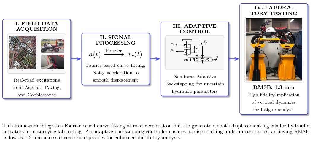
Accurate replication of road signal effects over the vehicles in laboratory environments is critical for vehicle durability testing and development. However, the traditional signal reconstruction methods often suffer from the inclusion of noise in the collected acceleration data. Thus, there is a limitation on the fidelity of hydraulic road simulations. This study proposes a comprehensive experimental-analytical framework for motorcycle testing in a laboratory environment. In the study, the integration of Fourier-based curve fitting with nonlinear adaptive control algorithms was done. Experimental signals were initially collected from a motorcycle on three different road surfaces. The displacement reference signals for the hydraulic actuators were generated using a harmonic curve-fitting approach from these signals. The performance analysis of the reconstruction signals was investigated in both the time and frequency domains. To ensure accurate trajectory tracking performance under parametric uncertainties, an adaptive backstepping control algorithm was designed. Experimental results revealed the superior performance of the proposed controller at all three road profiles, achieving Root Mean Square Errors (RMSE) as low as 1.3 mm. The controller exhibited robustness, maintaining consistent tracking precision with negligible performance variance across significantly different road characteristics, thereby validating the framework's utility for fatigue analysis.
Keywords:
road simulation
; fourier curve fitting
; adaptive backstepping control
; motorcycle dynamics
; hydraulic actuator
1. Introduction
The rapid evolution of the automotive industry demands careful validation of vehicle durability, ride comfort, and safety standards. It is significantly shifting the core focus from time-consuming proving ground tests to laboratory-based road test rigs. Hydraulic road test rigs have appeared as the backbone of this validation process. These test rigs offer the critical ability to replicate complex road-vehicle interactions in a repeatable and controlled environment. However, achieving high-fidelity reproduction of real-world dynamics within a test rig remains a formidable engineering challenge due to the nonlinearities of hydraulic actuators and the complexity of generating accurate input reference signals from collected acceleration data. However, acceleration data include noise, so transforming them to displacement trajectories is not straightforward. Traditional signal processing methods often fail to preserve the primary characteristics of the road profile, resulting in differences between the road and the test rig. Furthermore, even with a perfect reference signal, standard controllers often struggle to maintain tracking precision against the parametric uncertainties of hydraulic systems. Motivated by these limitations, this study introduces a unified experimental-analytical framework. By integrating Fourier-based curve fitting with a nonlinear adaptive control strategy, this research aims to provide a robust methodology for high-fidelity motorcycle durability testing.
A significant body of research has focused on virtual simulation models of motorcycle and bicycle dynamics. He et al. [1] developed a comprehensive multi-degree-of-freedom model that incorporates steering geometry, tire slip dynamics, frame flexibility, and rider inputs; their work particularly enables realistic roll–steer behavior in interactive riding simulations. Shoman and Imine [2] systematically improved model accuracy by comparing simulation results with data collected from a physical bicycle prototype, thereby enhancing the dynamic consistency and educational potential of riding simulators. Owczarkowski et al. [3] analyzed the tipping dynamics of bicycles in detail within an LQR-based stabilization framework and examined the influence of controller design on stability across different speed conditions. Zhao et al. [4] experimentally and numerically investigated the effects of rider biomechanics on system response in suspension-equipped cycling trainers, providing detailed insight into the role of human–bicycle interaction in vertical vibration performance. Since earlier research has primarily relied on synthetic or simplified excitations, there is a clear need to validate hydraulic systems with real-world reference signals. Motivated by this necessity, the authors focused on the high-fidelity reconstruction of real road signals, establishing a wide dataset through comprehensive motorcycle experiments on the road.
Another major direction in the literature concerns the estimation of road profiles or vehicle parameters based on onboard measurements. Deep learning–based reconstruction methods [5], sliding-mode observers and optimization techniques for bicycle parameter identification [6,7], and sensor-fusion-based estimation strategies such as the adaptive Kalman filtering framework of Arat et al. [8] demonstrate strong capabilities for inferring road disturbances and suspension states. Similar studies estimate road roughness characteristics [9], while Yao et al. [10] propose UKF-based harmonic identification techniques. These contributions provide valuable bases for signal estimation. However, the reference signal reproduction is inherently an offline process, the authors adopted a harmonic curve-fitting technique due to its ease of implementation and high performance. This method allows for the straightforward conversion of field data into trackable trajectories, the effectiveness of which was validated through direct application on a real-world test rig.
Parallel to the advancements in signal reproduction, the design of control architectures constitutes the other fundamental pillar for system analysis. Active and semi-active suspension control research offers yet another relevant domain. Time-delay feedback control [11], sliding-mode control with extended state definitions [12], nonlinear adaptive schemes [13], and reinforcement-learning-based semi-active control validated through road testing [14] have all demonstrated significant improvements in vibration mitigation. Kararsiz et al. [15] introduced an adaptive control framework combined with disturbance observers to compensate for unknown road inputs, while Paksoy and Metin [16] proposed a nonlinear semi-active adaptive vibration control strategy validated via HIL experiments on a half-vehicle model. The literature most closely related to the present work focuses on hydraulic road simulators and shaking tables. Chindamo et al. proposed a motorcycle road simulator architecture [17] and demonstrated four-poster reproduction of road profiles for durability testing [18]. Azizi et al. [19] designed and experimentally evaluated an electro-hydraulic road-excitation simulator, while Shen et al. [20] introduced feed-forward inverse control for transient waveform replication. Metin et al. [21] demonstrated that their proposed controller enables the hydraulic cylinder to track reference road inputs more accurately, particularly by effectively suppressing the nonlinear effects arising from pressure dynamics and load variations through the backstepping structure. Dursun and Bayram [22] presented a model-based iterative learning control (ILC) strategy—where repeated execution of the same trajectory enables cycle-to-cycle improvement in tracking accuracy. In addition, modeling and control of hydraulic test systems have been addressed in the literature. Taşağıl et al. [23] presented modeling and parametric analysis of elastomer material test systems, while Taşağıl et al. [24] implemented adaptive fuzzy PID control on a hydraulically driven axle shaft test system. These studies highlight the importance of adaptive control strategies in hydraulic test rigs operating under varying load conditions and parameter uncertainties. As a result, the tracking performance in hydraulic systems results from the interaction between the supply pressure, the servo-valve dynamics, and the external load forces. Nonlinearities significantly influence the control precision of the system. The integration of adaptive control mechanisms can further improve tracking behavior by compensating for parametric uncertainties and varying operating conditions. The high control performance of adaptive algorithms in nonlinear systems has led researchers to extend their use in systems requiring multi-physics modeling, such as hydraulic road simulators.
The significance of accurate reference reproduction in road simulation, combined with the demonstrated tracking capability of adaptive control algorithms for hydraulic systems, underscores the necessity of a unified testing framework. This study proposes a methodology that integrates Fourier-based curve fitting with adaptive control algorithms for motorcycle testing. The proposed approach overcomes the mathematical constraints of direct integration. The novelty of this work can be summarized as follows:
- By employing a Fourier-based curve fitting method, the proposed framework enables the transformation of noisy acceleration data into smooth, differentiable displacement trajectories. This significantly enhances the quality of the reference signal available for the control system, thereby improving tracking accuracy.
- Beyond signal processing, the proposed methodology implements an adaptive control law that estimates hydraulic parameters in real-time. This provides a more accurate representation of the system dynamics under varying road loads, directly enhancing the performance of the test rig in reproducing real-world vibrations.
- The framework also enables the rigorous testing of motorcycle durability in a laboratory environment, ensuring that the most realistic road-induced excitations are utilized for subsequent fatigue analysis and vehicle development.
Consequently, the present study proposes a comprehensive experimental–analytical framework for reproducing real-road motorcycle vertical dynamics in laboratory conditions. Acceleration data were collected on three road surfaces—smooth asphalt, cobblestone, and pavement stones—while towing the motorcycle to eliminate engine-induced vibration. The measured vertical accelerations were harmonically reconstructed via curve fitting and transformed to displacement reference signals. These trajectories were then applied to a vertically actuated hydraulic cylinder controlled by a nonlinear adaptive backstepping algorithm developed for a motorcycle. The adaptive laws updated uncertain hydraulic parameters associated with effective bulk modulus, flow–pressure characteristics, and other unmodeled dynamic effects. Experiments conducted on a 1-kHz real-time industrial controller demonstrated that the proposed framework successfully reproduces the dominant features of real-road motorcycle accelerations across all tested surfaces.
2. Methodology
In the methodology section, the overall methodological framework used in the study is presented. The workflow of the study consists of four main stages: data acquisition, signal processing, test system design, and control algorithm development. Firstly, acceleration data were collected from a motorcycle driven within the campus of Yıldız Technical University, İstanbul. In this stage, an accelerometer was integrated into the motorcycle to measure real road-induced vibrations during riding. The general structure of the proposed methodology is shown in Figure 1. After data acquisition, the aim was to obtain the displacement motion of the hydraulic pistons in the laboratory test rig. To achieve this, the measured acceleration signal was transformed into a displacement reference signal. The transformation was performed by fitting the acceleration data using multiple harmonic components. After that, they were transformed to obtain the equivalent displacement profile. This displacement signal was used as the reference trajectory for the hydraulic piston system. The test rig was designed to drive a full-scale motorcycle using two hydraulic pistons mounted at the front and rear ends. After establishing a safe and stable operating procedure, the motorcycle was securely fixed to the test platform. The proposed control algorithm implemented on the rig was an adaptive control strategy, developed to compensate for uncertainties in the hydraulic-piston system parameters. A detailed analysis of each component of the study is presented in the subsequent sections.
2.1. Data Acquisition
This section presents the procedure for collecting data obtained during actual driving, which is necessary for extracting the reference signals of the hydraulic pistons required for establishing the test system to be developed in a laboratory environment for industrial applications. The test system is aimed to be designed for motorcycle fatigue and endurance testing. During the data collection, the acceleration data over the motorcycle were collected at different road types, such as asphalt, paving stones, and cobblestones, and at different motorcycle velocities. For this data collection procedure, a Honda Monkey model motorcycle was used at the Yıldız Technical University in Turkey for the data acquisition. The test area can be seen in Figure 2
In the test area,
- Red marked road: Asphalt Road
- Blue marked road: Paving Stones
- Yellow marked road: Cobblestones
During the driving, the aim is to create frequency and amplitude variety in the data obtained by collecting measurement data from three different road types. During the measurements, the motorcycle speed was selected in accordance with the traffic rules for the road used. There are also numerous speed bumps on the selected route. Thus, road-induced impact effects on the motorcycle will also be included in the tests.
2.2. Curve Fitting
The accurate representation of road-induced excitations is essential for reproducing realistic dynamic responses, especially for the analysis of the fatigue effect on the vehicles in the laboratory environment. The acceleration signals collected from the motorcycle were used to reconstruct the equivalent displacement trajectories due as the direct measurement of the road displacement profile is often impractical in on-road experiments. This reconstruction serves as the base for developing the reference signal of the hydraulic pistons in the test rig. Thus, the experimentally acquired acceleration signals were transformed into displacement signals of the pistons that excite the motorcycle in the industrial application. For this transformation, a Fourier-based curve-fitting approach that was shown in Eq. (1) was employed, assuming that the acceleration response induced by road irregularities can be expressed as a superposition of harmonic components. This assumption is widely accepted in road surface modeling and enables an efficient frequency-domain characterization of the measured data.
In the curve fitting analysis, three different road acceleration signals(asphalt, paving, and cobblestones) were investigated. The acceleration signals were then reconstructed using 144 harmonic components distributed across 72 distinct frequency values. Each harmonic signal was characterized by its amplitude and frequency, providing a detailed frequency-domain representation of the road-induced excitation. Consequently, the fitted profiles closely replicated the experimentally measured acceleration data, as presented in Table 1. The coefficient of determination () approached unity, indicating an ideal fit, while both the root mean square error (RMSE) and mean absolute error (MAE) values were found to be low. The mathematical representation of the performance indices was shown between Eq. (2) and (4). An illustration between the measured and reconstructed signals, shown in Figure 3, confirms the strong correlation and demonstrates that the fitted curve accurately captures both the periodic and transient characteristics of the measured acceleration data. The amplitude spectrum of the harmonic components is illustrated in Figure 4. The high agreement between the experimental and fitted responses validates the effectiveness of the Fourier-based harmonic decomposition approach for generating representative road excitation profiles. This process forms the foundation for the dynamic analysis and control algorithm testing performed in the subsequent sections under realistic excitation conditions.
In these equations, N denotes the total number of data points, while and represent the actual measured acceleration values and the predicted values, respectively. Additionally, indicates the mean of the actual measurements, corresponds to the residual sum of squares, and represents the total sum of squares. A and B are the coefficients of the harmonic signals, f is the frequency, and t represents time.
Figure 3.
The filtered and the fitted signal comparison, (a) Cobblestones time domain, (b) Cobblestones frequency domain, (c) Paving stones time domain, (d) Paving stones frequency domain, (e) Asphalt road time domain, (f)Asphalt road frequency domain
Figure 3.
The filtered and the fitted signal comparison, (a) Cobblestones time domain, (b) Cobblestones frequency domain, (c) Paving stones time domain, (d) Paving stones frequency domain, (e) Asphalt road time domain, (f)Asphalt road frequency domain

Figure 5.
The physical representation of the hydraulic piston system

Figure 4.
Analysis of the fitted harmonic signal components and the reference trajectory: (a-d-g) cosine coefficients of the fitted harmonic signal, (b-e-h) sine coefficients of the fitted harmonic signal (c-f-i) the reference piston signal
Figure 4.
Analysis of the fitted harmonic signal components and the reference trajectory: (a-d-g) cosine coefficients of the fitted harmonic signal, (b-e-h) sine coefficients of the fitted harmonic signal (c-f-i) the reference piston signal

In Figure 4(c), the reference piston signal derived from the acceleration signal can be seen. After identifying the reference signal for the control algorithm, the error signal is created from the reference signal and the system feedback signal during the control signal design. In the next section, the design of the control algorithm will be examined.
2.3. Adaptive Control Design
In this section, the adaptive control algorithm design for the trajectory tracking control of the hydraulic piston systems will be presented. The illustration of the hydraulic piston system was shown in Figure 5 and the parameter list can be seen in Table 2
In the hydraulic system, the electric current will be designed as the control input of the system that controls the hydraulic actuator response by generating a pressure difference between the upper and lower chambers of the hydraulic piston. This pressure differential, denoted by PL() as shown in Figure 5, varies as a function of time and directly determines the vertical displacement of the piston rod. Consequently, the controlled motion of the hydraulic piston induces vertical vibrations on the motorcycle structure mounted on the test platform, thereby replicating the real road-induced excitation under laboratory conditions. The mathematical model of the hydraulic system, corresponding to the physical configuration shown in Figure 5, is defined between Eq. 5 and Eq. 6.
where is the piston mass; is piston displacement; , are piston velocity and acceleration,respectively; is the piston effective area; is the valve-related pressure differential state; is the time derivation; u is the valve command input; is the supply pressure; is the signum function of u; is the fluid bulk modulus; V is the hydraulic control volume; is the leakage conductance; is the discharge coefficient; w is the valve spool gradient; is the electrical gain; is the fluid density; ,, are coefficients defined in Eq. 7. The parameters , , and in Eq. (7) will be defined as adaptive parameters. These parameters were selected as the uncertain parameters in the hydraulic piston system due to handling parametric uncertainties, such as variations in the effective bulk modulus () resulting from temperature changes. The adaptation parameter represents the hydraulic stiffness term relating to the piston velocity dynamics, characterizes the total leakage coefficient () of the system, and represents the control input gain (control effectiveness), which is directly influenced by the discharge coefficient () and the valve spool gradient (w).
To quantify the control objective, the tracking error signal was defined as Eq. 8
where is the scalar error signal between the reference piston displacement signal and the piston displacement signal. The candidate Lyapunov function can be defined as Eq. 9 to investigate the stability analysis of the system
where and represent the intermediate state between the virtual control signals( and the system states(,). The notation denotes the estimated value of a variable , while the estimation error between the actual and estimated parameters is defined as . The intermediate state can be found in Eq. 10 and Eq. 11.
where the virtual control signals and are introduced as part of the back-stepping design to facilitate the derivation of the actual control input. The time derivative of the virtual control signal in Eq. 12 and Eq. 13 are incorporated into the derivation of Eq. 9.
Accordingly, the time derivative of the candidate Lyapunov function is obtained as in Eq. 14
The proposed control algorithm is formulated as shown in Eq. 15
where , and are the user defined positive control gains. The adaptation laws for the estimated parameters can be found in Eq. 16
When the control gains , and are appropriately selected, the end of the stability analysis can be expressed as
From the candidate Lyapunov function in Eq. 9 and its time derivative in Eq. 17, it can be observed that, when the control gains , and are selected to be appropriately, (i.e., is bounded). Consequently, the signal is also bounded. It can be concluded that . Finally, by the direct application of Barbalat’s Lemma [25], we obtain
2.4. Experimental Setup
In this section, the experimental framework established to validate the proposed adaptive control algorithm is presented. The methodology bridges the gap between field operational conditions and laboratory simulation by integrating real-world data acquisition with a testing environment. First, field measurements were conducted to capture the vertical acceleration response of the motorcycle on various road terrains, serving as the basis for the curve-fitted reference signals described in the previous section. Subsequently, a custom-designed motorcycle hydraulic test rig was utilized to reproduce these road profiles under controlled conditions. The detailed specifications of the mechanical configuration, the hydraulic actuation system, and the data acquisition infrastructure are provided in the following subsections.
2.4.1. Mechanical Configuration and Hydraulic Actuation
The experimental framework developed for this study is configured as a dual-actuator motorcycle test system, designed to validate the effectiveness of adaptive control algorithms under laboratory conditions. This setup allows for the independent control of the front and rear wheel displacements. The configuration is designed to reproduce driving scenarios accurately by exposing the motorcycle tires to vertical excitations that mimic real-world road profiles. The setup was built on high-rigidity steel construction. The actuation system utilizes two custom-manufactured hydraulic cylinders with a piston diameter of mm, a rod diameter of mm, and a maximum stroke length of 125 mm. These cylinders are positioned to transfer vertical motion directly to the contact patches of the motorcycle tires. To maintain kinematic stability and prevent the vehicle from tipping during dynamic testing, lateral stabilizer arms were integrated into the frame. These arms provide a kinematic constraint that permits free vertical translation (heave and pitch motion) while rigidly restricting lateral roll and yaw degrees of freedom. To address the nonlinear flow characteristics inherent in hydraulic systems, MOOG D661-6487C high-performance servo valves are employed. These valves are critical for enhancing the system’s dynamic response, enabling high-fidelity tracking of road inputs within the low-to-medium frequency range (0–25 Hz), which corresponds to the primary bandwidth of vehicle suspension dynamics.
2.4.2. Control Architecture and Data Acquisition
The control infrastructure is built upon the automation architecture, selected for its deterministic real-time processing capabilities. The control algorithms, including the proposed adaptive control law, are embedded in the system within the Automation Studio environment and executed on a APC910 industrial PC. This controller manages the exchange of data between the servo valves, integrated linear scales, and pressure sensors via analog and digital input/output modules. The system operates with a closed-loop cycle time sufficiently low to ensure the stability of the adaptive parameters during the transient time.
The sensors are rigidly mounted on the motorcycle frame and the hydraulic part of the test rig. These measurements are synchronously recorded by the APC910 unit, allowing for a direct comparison between the reference road profile and the actual vehicle body response. The experimental test setup is powered by two independent hydraulic actuators, capable of reproducing dynamic loads similar to real-world road conditions in a laboratory environment. This structure allows for the analysis of vehicle body behaviors similar to those of real-world driving conditions by applying data from different road profiles in a controlled manner.
3. Results
The experimental investigation was done to validate the performance and robustness of the proposed adaptive control algorithm within the hydraulic piston displacement control framework. The control strategy was implemented through an Automation PC (APC), which served as the real-time control unit responsible for implementing the adaptive control algorithm and transferring the control signals to the servo-valve system. During the experimental tests, two hydraulic actuators were driven with a 100-ms delay between rear and front hydraulic pistons by the control signals to generate vertical displacements that imitate the dynamic behavior of different road disturbances. These controlled motions were transmitted to the motorcycle on the test platform, thereby reproducing realistic ride excitations under laboratory conditions. Through the test system, the proposed adaptive control signal was evaluated for maintaining accurate displacement tracking and system stability.
The first experimental validation of the proposed adaptive control scheme was conducted using the Cobblestone road profile, which characterizes a specific variation of road surface irregularities. The corresponding system response is presented in Figure 6. In Figure 6(a), the tracking performance of the proposed controller scheme at the displacement signals of both the front and rear pistons was shown to be superior. Despite the nonlinear dynamics in the system, the tracking error signals between the reference and measured ones remain minimal throughout the duration of the test. Figure 6(b) and Figure 6(c) show the control signals generated by the adaptive control. Furthermore, the effectiveness of the adaptation mechanism is evidenced by the evolution of the estimated parameters shown in Figure 6(d)-(f). The parameters, , , and representing the hydraulic stiffness, leakage, and control gain, rapidly converge to stable values after an initial transient phase.
In addition to the Cobblestone road profile, the system was investigated by the Paving Stones road profile to evaluate the controller’s robust performance under different road conditions. The experimental results for the scenario are illustrated in Figure 7. As shown in Figure 7(a), the reference trajectory tracking performance at the rear and front cylinders can be seen as superior. The tracking performance of the proposed controller demonstrates the robustness of the adaptive controller design. The control signals were presented in Figure 7(b) and Figure 7(c). It can be seen that the front actuator requires a higher magnitude of control input (u) during the initial high-amplitude excitation (especially s) compared to the rear actuator. Finally, the update of the adaptation parameters was illustrated in Figure 7(d)-(f).
In the last test investigation, the proposed controller algorithm’s performance was evaluated under the Asphalt road profile, which represents typical highway driving road conditions. The experimental results are shown in Figure 8. As shown in Figure 8(a), the designed adaptive controller achieves excellent tracking accuracy. The magnitude of the control signals is presented in Figure 8(b) and Figure 8(c). The required control voltages are significantly lower than the control input voltages at Cobblestone and Paving stones. The adaptive parameters were shown in Figure 8(d)-(f). These three distinct road profiles with varying characteristics validate the reliability and repeatability of the proposed adaptive control strategy for real-world suspension testing applications. As summarized in Table 3, the numerical metrics confirm the superiority of the proposed framework. The Root Mean Square Error (RMSE) values remain consistently low across varying road profiles, demonstrating the robustness of the control algorithm against different disturbances. Furthermore, the minimal standard deviation of the tracking error indicates high precision and a smooth control response with negligible chattering.
The additional investigations in future studies can add to the understanding and applicability of the proposed adaptive control approach in real-world motorcycle testing environments. Potential additional researches for future research are summarized below:
- The adaptive control law can be further improved by integrating machine learning–based controllers to improve the adaptation to time-varying road conditions automatically.
- The hydraulic actuation system could be enhanced through the use of high-response servo valves to achieve higher-frequency tracking capability.
-
Real-road data acquisition could be expanded to include various weather conditions and loading scenarios to assess the robustness and generalizability of the proposed method.These extensions can widen the applicability of the proposed framework and contribute to the development of intelligent, high-fidelity motorcycle simulators capable of realistic road signals.
4. Conclusions
This study has successfully established a comprehensive experimental-analytical framework for motorcycle testing in a laboratory environment. In the framework, integration of Fourier-based curve fitting with a nonlinear adaptive backstepping control algorithm was done. Thus, the proposed methodology effectively overcomes the limitations associated with noise in traditional signal reconstruction. The performance investigation of the framework was conducted across three different road surfaces, while the adaptive controller ensures superior trajectory tracking performance despite parametric uncertainties at the hydraulic valve. The numerical performance results also show the superior performance of the system, achieving Root Mean Square Errors as low as 1.3 mm and a low standard deviation. Furthermore, the controller displayed remarkable robustness, maintaining consistent performance with low tracking error at the different road characteristics. Consequently, this framework validates itself as a reliable and effective tool for rigorous fatigue analysis and vehicle development, offering a high-fidelity alternative to costly on-road testing.
Author Contributions
Visualization, writing—original draft preparation, investigation, F.C.Y.; methodology, conceptualization, formal analysis, writing—review and editing, supervision, project administration, and data obtaining, M.M.; testing, writing—original draft preparation, and investigation, T.O. All authors have read and agreed to the published version of the manuscript.
Data Availability Statement
The data presented in this study are available on request from the corresponding author. The data are not publicly available due to their large volume and the ongoing nature of related research projects.
Acknowledgments
During the preparation of this manuscript, the authors used Gemini solely for the purpose of improving the English grammar of sentences. The authors have reviewed and edited the output and take full responsibility for the content of this publication.
Conflicts of Interest
The authors declare no conflict of interest.
References
- Q. He, X. Fan, and D. Ma, “Full bicycle dynamic model for interactive bicycle simulator,” in Journal of Computing and Information Science in Engineering, vol. 5, pp. 373–380, 2005. [CrossRef]
- M. M. Shoman and H. Imine, “Bicycle simulator improvement and validation,” in IEEE Access, vol. 9, pp. 55063–55076, 2021.
- A. Owczarkowski, D. Horla, P. Kozierski, and T. Sadalla, “Dynamic modeling and simulation of a bicycle stabilized by LQR control,” in Proceedings of the 21st International Conference on Methods and Models in Automation and Robotics (MMAR), Miedzyzdroje, Poland, 2016, pp. 907–911. [CrossRef]
- L. Zhao, Y. Yu, and C. Zhou, “Dynamic modeling, simulation and experimental investigation on cycling-trainers equipped with suspensions considering human biomechanical characteristics,” in Journal of Vibroengineering, vol. 22, pp. 1228–1239, 2020.
- G. Kim, S. Y. Lee, J. S. Oh, and S. Lee, “Deep learning-based estimation of the unknown road profile and state variables for the vehicle suspension system,” in IEEE Access, vol. 9, pp. 13878–13890, 2021.
- H. Imine, T. Madani, and M. Shoman, “Dynamic parameter identification of a bicycle using sliding mode observer and particle swarm optimization,” in Highlights of Vehicles, vol. 3, pp. 15–29, 2025.
- H. Imine, L. Fridman, and T. Madani, “Identification of vehicle parameters and estimation of vertical forces,” in International Journal of Systems Science, vol. 46, pp. 2996–3009, 2015.
- M. A. Arat, E. Holweg, and S. Taheri, “Road profile estimation for active suspension applications,” in SAE International Journal of Passenger Cars - Mechanical Systems, vol. 8, pp. 492–500, 2015.
- A. Čerškus, T. Lenkutis, N. Šešok, A. Dzedzickis, D. Viržonis, and V. Bučinskas, “Identification of road profile parameters from vehicle suspension dynamics for control of damping,” in Symmetry, vol. 13, p. 1149, 2021.
- J. Yao, R. Xiao, S. Chen, D. Di, S. Gao, and H. Yu, “Acceleration harmonic identification algorithm based on the unscented Kalman filter for shaking signals of an electro-hydraulic servo shaking table,” in Journal of Vibration and Control, vol. 21, pp. 3205–3217, 2015.
- Y. Nan, S. Shao, C. Ren, K. Wu, Y. Cheng, and P. Zhou, “Simulation and experimental research on active suspension system with time-delay feedback control,” in IEEE Access, vol. 11, pp. 88498–88510, 2023.
- T. A. Nguyen, “Advance the efficiency of an active suspension system by the sliding mode control algorithm with five state variables,” in IEEE Access, vol. 9, pp. 164368–164378, 2021.
- A. A. J. I. Wijaya, F. Yakub, S. S. Abdullah, S. Aljazzar, and M. A. S. Kamal, “Adaptive estimation and control of nonlinear suspension systems with natural logarithm sliding mode control,” in IEEE Access, vol. 12, pp. 60896–60907, 2024. [CrossRef]
- J. Ultsch, A. Pfeiffer, J. Ruggaber, T. Kamp, J. Brembeck, and J. Tobolář, “Reinforcement learning for semi-active vertical dynamics control with real-world tests,” in Applied Sciences, vol. 14, p. 7066, 2024.
- G. Kararsiz, M. Paksoy, M. Metin, and H. I. Basturk, “An adaptive control approach for semi-active suspension systems under unknown road disturbance input using hardware-in-the-loop simulation,” in Transactions of the Institute of Measurement and Control, vol. 43, pp. 995–1008, 2021. [CrossRef]
- M. Paksoy and M. Metin, “Nonlinear semi-active adaptive vibration control of a half vehicle model under unmeasured road input,” in Journal of Vibration and Control, vol. 25, pp. 2453–2472, 2019.
- D. Chindamo, M. Gadola, D. Armellin, and F. Marchesin, “Design of a road simulator for motorcycle applications,” in Applied Sciences, vol. 7, p. 1220, 2017. [CrossRef]
- D. Chindamo, M. Gadola, and F. P. Marchesin, “Reproduction of real-world road profiles on a four-poster rig for indoor vehicle chassis and suspension durability testing,” in Advances in Mechanical Engineering, vol. 9, pp. 1–10, 2017.
- M. J. Azizi, M. Mirzaei, S. Rafatnia, and T. F. Nodeh, “Design and experimental evaluation of road excitation simulator,” in Journal of Theoretical and Applied Vibration and Acoustics, 2024.
- G. Shen, G. M. Lv, Z. M. Ye, D. C. Cong, and J. W. Han, “Feed-forward inverse control for transient waveform replication on electro-hydraulic shaking table,” in Journal of Vibration and Control, vol. 18, pp. 1474–1493, 2012.
- M. Metin, F. C. Yılmaz, G. Taşağıl, T. Bayram, and F. Yiğit, “Nonlinear backstepping control of a hydraulic simulator for reference road input,” in Pamukkale University Journal of Engineering Sciences, vol. 31, pp. 1–8, 2025.
- U. Dursun and T. Bayram, “Tracking control solution for road simulators: Model-based iterative learning control approach improved by time-domain modelling,” in Gazi University Journal of Science, vol. 25, pp. 467–477, 2012.
- G. Taşağıl, B. Başgöl, M. Metin, and T. Bayram, “Elastomer karakterizasyon test sistemlerinin modellenmesi ve parametrik analizleri,” in European Journal of Science and Technology, 2020. [Online]. [CrossRef]
- G. Taşağıl, M. Metin, and T. Bayram, “Hidrolik tahrikli aks mili test sisteminin adaptif bulanık PID ile kontrolü,” in Mühendis ve Makina, vol. 64, pp. 17–38, 2023.
- J.-J. E. Slotine and W. Li, Applied Nonlinear Control. Englewood Cliffs, NJ, USA: Prentice Hall, 1991.
Figure 1.
The workflow of the study

Figure 2.
Overview of the data acquisition system and test track: (a) the test area in Yıldız Technical University, (b) the motorcycle equipped with the measurement unit, (c) close-up view of the acceleration sensor placement.
Figure 2.
Overview of the data acquisition system and test track: (a) the test area in Yıldız Technical University, (b) the motorcycle equipped with the measurement unit, (c) close-up view of the acceleration sensor placement.

Figure 6.
Experimental results of the hydraulic-piston test rig for the Cobblestone road (a-b) trajectory tracking performance of the front and rear hydraulic pistons compared to the reference displacement signal; (c-d) control input voltage signals for the front and rear actuators, (e-j) the update of the adaptive parameters for the front and rear hydraulic pistons, , and

Figure 7.
Experimental results of the hydraulic-piston test rig for the Paving Stones road (a-b) trajectory tracking performance of the front and rear hydraulic pistons compared to the reference displacement signal; (c-d) control input voltage signals for the front and rear actuators, (e-j) the update of the adaptive parameters for the front and rear hydraulic pistons, , and

Figure 8.
Experimental results of the hydraulic-piston test rig for the Asphalt road (a-b) trajectory tracking performance of the front and rear hydraulic pistons compared to the reference displacement signal; (c-d) control input voltage signals for the front and rear actuators, (e-j) the update of the adaptive parameters for the front and rear hydraulic pistons, , and


Table 1.
Performance evaluation of the curve-fitting algorithm
| Road Type | RMSE | MAE | |
|---|---|---|---|
| Cobblestones | 0.9694 | 8.8184 | 7.5211 |
| Paving Stones | 0.9451 | 11.8205 | 9.8296 |
| Asphalt Road | 0.9719 | 7.9879 | 6.9220 |
Table 2.
Parameter table
| Symbol | Definition | Unit | Value |
|---|---|---|---|
| m | Piston Mass | kg | 4 |
| A | Piston Area | ||
| Cylinder Internal Pressures | bar | - | |
| Supply Pressure | bar | 210 | |
| Piston Position | m | - | |
| Piston Velocity | m/s | - | |
| Pressure Difference | bar | - | |
| Hydraulic Oil Density | 850 | ||
| Oil Bulk Modulus | |||
| Leakage Coefficient | |||
| Discharge Coefficient | - | 0.62 | |
| Servo Valve Area Gradient | 0.024 | ||
| Total Cylinder Volume | |||
| Control Gains | - | 9800, 5000, 3600 | |
| Adaptation Gains | - | 700, 700, 700 |
Table 3.
Performance Metrics Of The Proposed Adaptive Controller For Front And Rear Suspension Systems Under Three Different Road Profiles
Table 3.
Performance Metrics Of The Proposed Adaptive Controller For Front And Rear Suspension Systems Under Three Different Road Profiles
| Road Profile | Location | RMSE (m) | Max. Error () | Std. Dev. () | Control Effort () |
|---|---|---|---|---|---|
| Cobblestone road | Front | 0.0013 | 0.0104 | 0.0011 | 0.3159 |
| Rear | 0.0032 | 0.0199 | 0.0031 | 0.1340 | |
| Paving Stones road | Front | 0.0015 | 0.0161 | 0.0014 | 0.3871 |
| Rear | 0.0041 | 0.0221 | 0.0040 | 0.1609 | |
| Asphalt road | Front | 0.0013 | 0.0160 | 0.0012 | 0.1440 |
| Rear | 0.0028 | 0.0208 | 0.0028 | 0.3306 |
Disclaimer/Publisher’s Note: The statements, opinions and data contained in all publications are solely those of the individual author(s) and contributor(s) and not of MDPI and/or the editor(s). MDPI and/or the editor(s) disclaim responsibility for any injury to people or property resulting from any ideas, methods, instructions or products referred to in the content. |
© 2026 by the authors. Licensee MDPI, Basel, Switzerland. This article is an open access article distributed under the terms and conditions of the Creative Commons Attribution (CC BY) license (http://creativecommons.org/licenses/by/4.0/).
Copyright: This open access article is published under a Creative Commons CC BY 4.0 license, which permit the free download, distribution, and reuse, provided that the author and preprint are cited in any reuse.


