
Submitted:
07 March 2026
Posted:
10 March 2026
You are already at the latest version
Abstract
The aerodynamic performance of an aircraft wing is influenced by the angle of attack (AoA), which directly affects lift, drag, and overall efficiency. This study presents a theoretical analysis of the effect of AoA on a symmetric thin aerofoil using aerodynamic models including Thin Aerofoil Theory and Lifting-Line Theory are discussed. Results are discussed under three regimes; linear AoA range where lift increases proportionally while maintaining steady improvement in lift to drag ratio, pre-stall regime where partial flow separation takes place by reducing lift growth, near-stall where flow separation causes deterioration in aerodynamic efficiency. The study highlights the importance of wing geometry including aspect ratio, camber, and sweep angle. Understanding complex interactions between AoA, lift generation, drag forces, and wing geometry is crucial for optimizing aircraft design and improving aerodynamic performance.
Keywords:
Angle of Attack (AoA)
; lift coefficient
; drag coefficient
; lift‐to‐drag ratio
; thin aerofoil theory
; lifting‐line theory
; stall behaviour
; aerodynamic efficiency
1. Introduction
Aerodynamics plays a major role in aircraft efficiency and performance. The Angle of Attack (AoA), defined as the angle between chord line of an aerofoil and oncoming airflow, is one of the most significant parameters which influences the aerodynamic forces.
The study of lift and drag with respect to AoA has been the backbone of many aerospace research. Usually computational fluid dynamics (CFD) simulations have shown that lift generally increases with AoA up to a critical angle, after which flow separation causes a sudden drop which is known as stall. Drag usually increases gradually at low angles of attack (AoA) but exhibits a sudden rise near stall. Understanding these core concepts is crucial for aircraft design phase and evaluation of performances and optimization.
CFD and Wind tunnel tests can be used to get more detailed analysis; theoretical methods such as aerofoil theory and parabolic drag are simple and more efficient. These methods allow engineers to estimate and analyse aerodynamic lift, drag, L/D ratio for different AoA without using costly experiments. The goal of this study is to analyse the effect of angle of attack on lift, drag and L/D for a generic aerofoil.
2. Literature Review
Generally aerodynamic forces are the forces generated as a natural consequence of a body moving through a fluid. Drag, the force parallel to the airflow, opposes the motion, and lift; the force perpendicular to the airflow that supports the body against gravity are the two main types of forces that are vital for the aircraft’s motion. Aerodynamic forces usually result from the pressure distribution, which acts perpendicular to the surface and shear distribution, acts parallel to the surface. The mathematical sum of these pressure and shear contribution is known as the resultant aerodynamic forces. These forces directly influence the performance and stability of aircraft and unmanned aerial vehicles (UAVs), One of the most vital factors, which govern lift and drag is AoA. National Advisory Committee for Aeronautics (NACA) is credited with conducting initial systematic study of aerofoils, which included extensive wind-tunnel experiments to understand the aerodynamic behaviour of aerofoils. The NACA aerofoil series provided standardized data on lift, drag, and pressure distribution. These experiments formed the foundation of determining relationship between aerofoil geometry, angle of attack (AoA) and aerodynamic forces. Alongside with these experimental studies, thin aerofoil theory laid the foundation for theories behind the understanding related to lift generation. As per the Thin-Aerofoil Theory, the lift on a thin aerofoil has a basic pattern at the ideal angle of attack, and it increases proportionally as the angle of attack changes from that point.
3. Problem Definition and Wing Modelling
Objective of the Study; The aim of this study is to analyse the impact of the variation of AoA affects the lift and drag characteristics of a generic wing model with a symmetric thin aerofoil. This study is mainly focused on quantify aerodynamic forces and provide insights into the flow behaviour under different AoA.
Definition of a Generic Wing; A generic wing is an idealized, simplified wing model used for fundamental aerodynamic analysis. Generic wing does not rely on specific aircraft model. However, it serves as a standard aircraft model to study about basic aerodynamic principles such as lift and drag.
Wing Platform and Aspect Ratio: A rectangular-shaped wing platform is considered, in order to maintain simplicity and for ease of the analysis. The aspect ratio (AR) of the wing is defined as (b= wingspan, S = wing planform area). A moderate
Aerofoil Type; A symmetric thin aerofoil is selected where the upper and lower surfaces are geometrically identical. Therefore, it produces zero lift at zero AoA in inviscid flow, eliminates camber effects, focusing purely on angle-of-attack variation. This leads to maintain the simplify the analysis.
4. Flow Assumptions and Theoretical Framework
- Steady Flow and Incompressible Conditions
The flow is assumed to be steady, all the flow properties such as velocity, pressure and density at a given spatial location are expected to remain constant with the time. This assumption is also valid for conditions involving constant freestream velocity and fixed AoA conditions such as cruise or wind-tunnel test.
- Incompressible
It is assumed that flow is incompressible, a constant density is maintained. This assumption is valid in the low Mach number regime (below 0.3) since Mach number increases towards speed of sound causing, compressibility effects like shock waves begin to significantly alter pressure distribution.
- Inviscid Outer Flow
Flow is considered as total inviscid outside the near-wall region. All the viscous stresses near the outer flow field are neglected.
- Boundary-Layer Treatment for Viscous Effects
The effect of viscosity is assumed to act only very close to the wing surface, in a thin layer called boundary layer. Inside this layer, the air slows down due to friction with the surface. Outside the boundary layer the flow is considered as inviscid. The boundary layer is often considered as a thinner layer than the wing and its pressure is equal to the outer flow. However, this assumption is valid for before flow separation occurs and only during normal flight conditions.
- Valid AoA range
Linear range: Lift varies linearly with angle of attack and the flow is fully attached.
Pre-stall range: Slightly nonlinear effects occur due to boundary layer growth, but the flow remains mostly attached (partial separation).
Post-stall range: Large scale flow separation dominates, lift decreases and drag increases
These assumptions make the analysis easier and match experiments well for low to moderate angles of attack.
5. Governing Equations
- Lift Coefficient ())
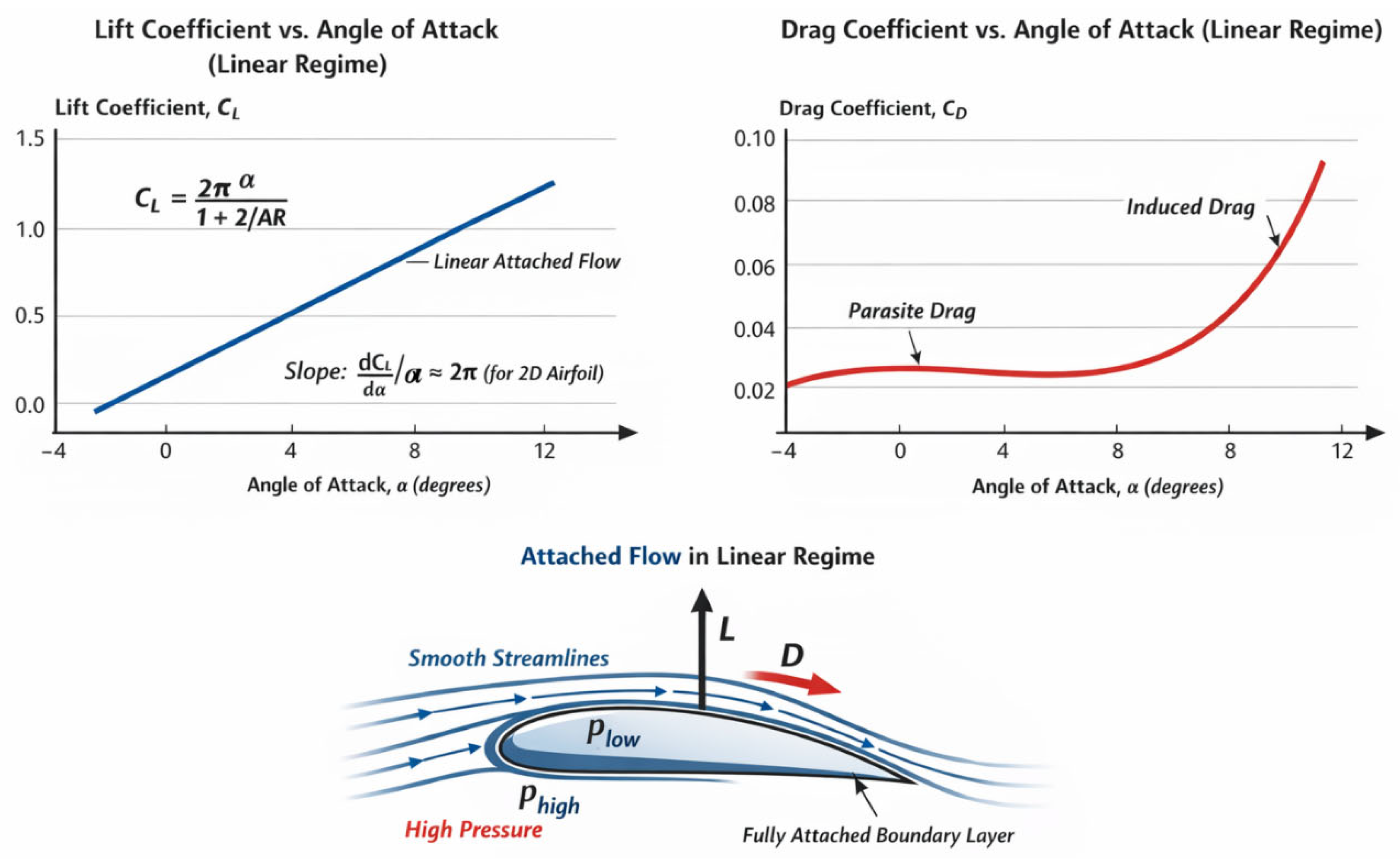
For a thin symmetrical aerofoil, the coefficient in the linear regime is given by thin aerofoil theory.
L =2π (radians)
where,
CL = Lift coefficient (dimensionless)
= AoA in radians
For finite wings, lifting-line theory modifies for induced effects;
L = AR = Aspect ratio of the wing = b= wingspan
S= planform area
This gives 3D lift coefficient for a rectangular wing.
- Drag Coefficient (CD)
CD = CDi + CDo
where,
CDi = Induced drag coefficient
CDo = viscous + pressure drag coefficient
- Induced Drag
Di =
where,
= Oswald efficiency factor (), accounts for wing planform and tip losses
= Aspect ratio
- Lift and Drag Forces
L
D
where
= Lift force (N)
= Drag force (N)
= Air density (kg/m³)
= Free-stream velocity (m/s)
= Wing planform area (m²)
- Lift-to-Drag Ratio (Aerodynamic Efficiency)
This ratio is crucial for understanding wing efficiency and optimal AoA.
=
6. Circulation Based Lift Generation
6.1. Definition of Circulation
Circulation related theories are used to describe the overall rotational motion of airflow around the aircraft’s wing. Circulation is defined as the integral of air flow velocity taken around a closed path enclosing the wing. In simple term the flow is a combination of uniform freestream motion and a small swirling motion around the wing that creates lift.
6.2. Generation Oof Circulation: Angle of Attack and Camber
Circulation is produced due to the shape of the aerofoil and its orientation to the oncoming flow.
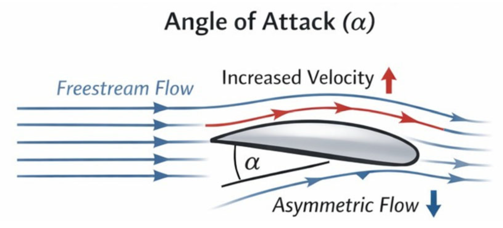
- Angle of Attack; When an aerofoil is inclined to the freestream, it deflects the airflow and creates an asymmetric velocity distribution that induces circulation.
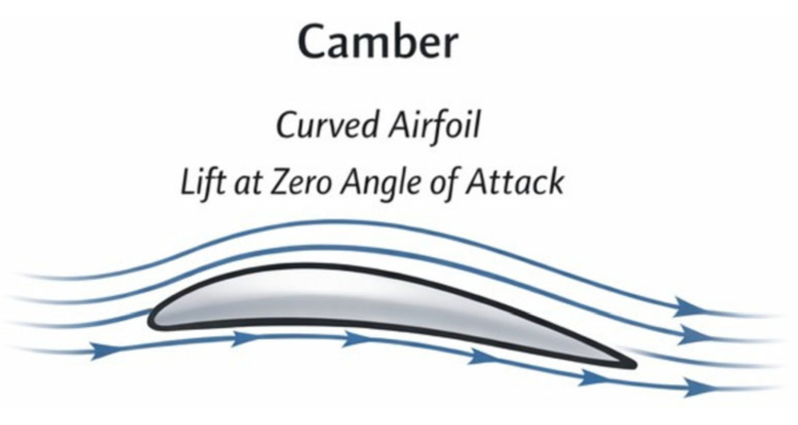
- Camber; Due to the curved shape of the cambered aerofoil circulation is naturally established. This allows lift to be generated even at zero angle of attack.
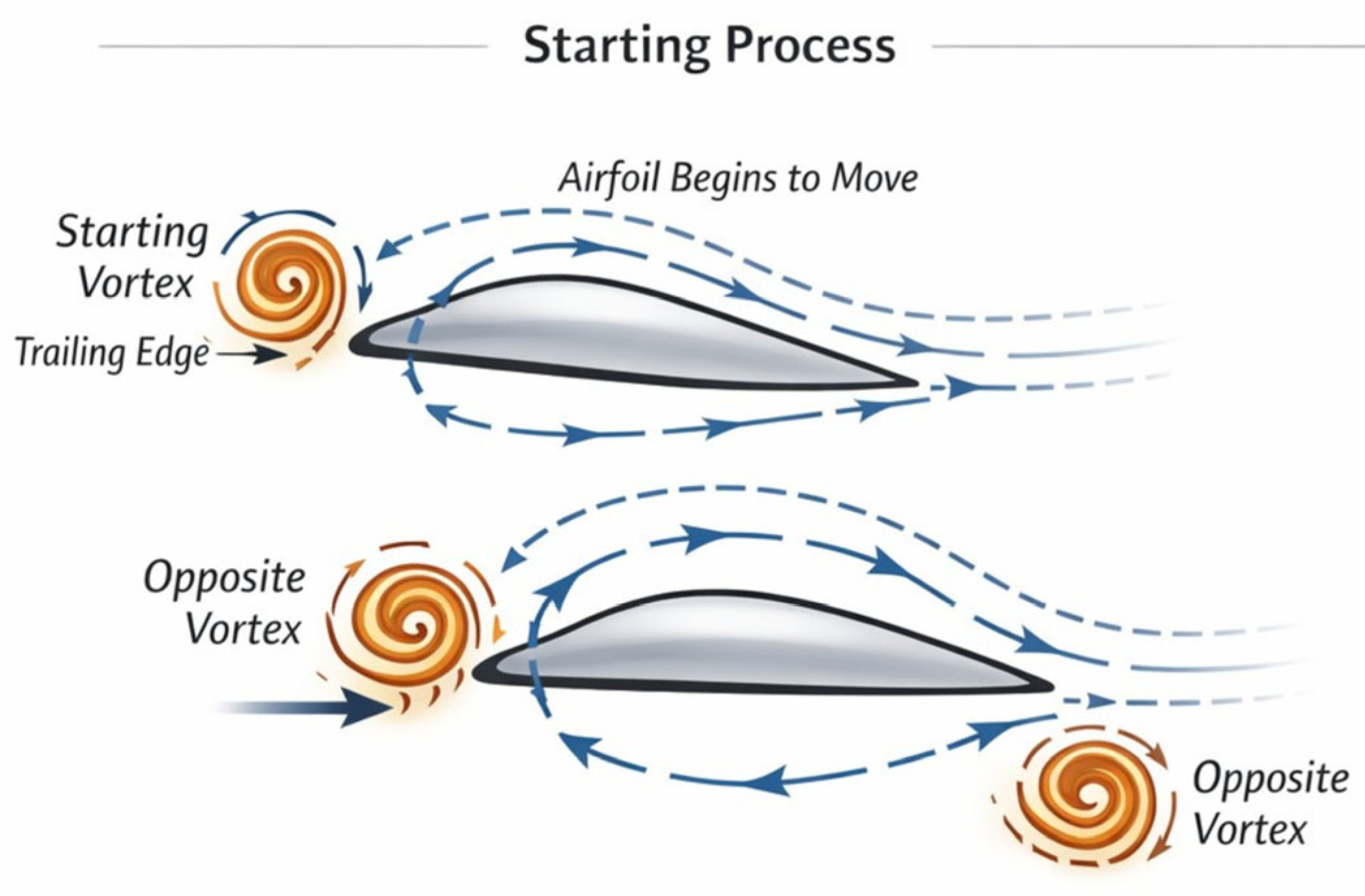
- Starting Process; When the aerofoil starts moving, a starting vortex is generated at the trailing edge due to the viscous effect. In order to conserve the circulation an equal and opposite bound circulation is formed around the aerofoil. This circulation around the aerofoil helps to generate lift.
6.3. Role of Kutta Condition
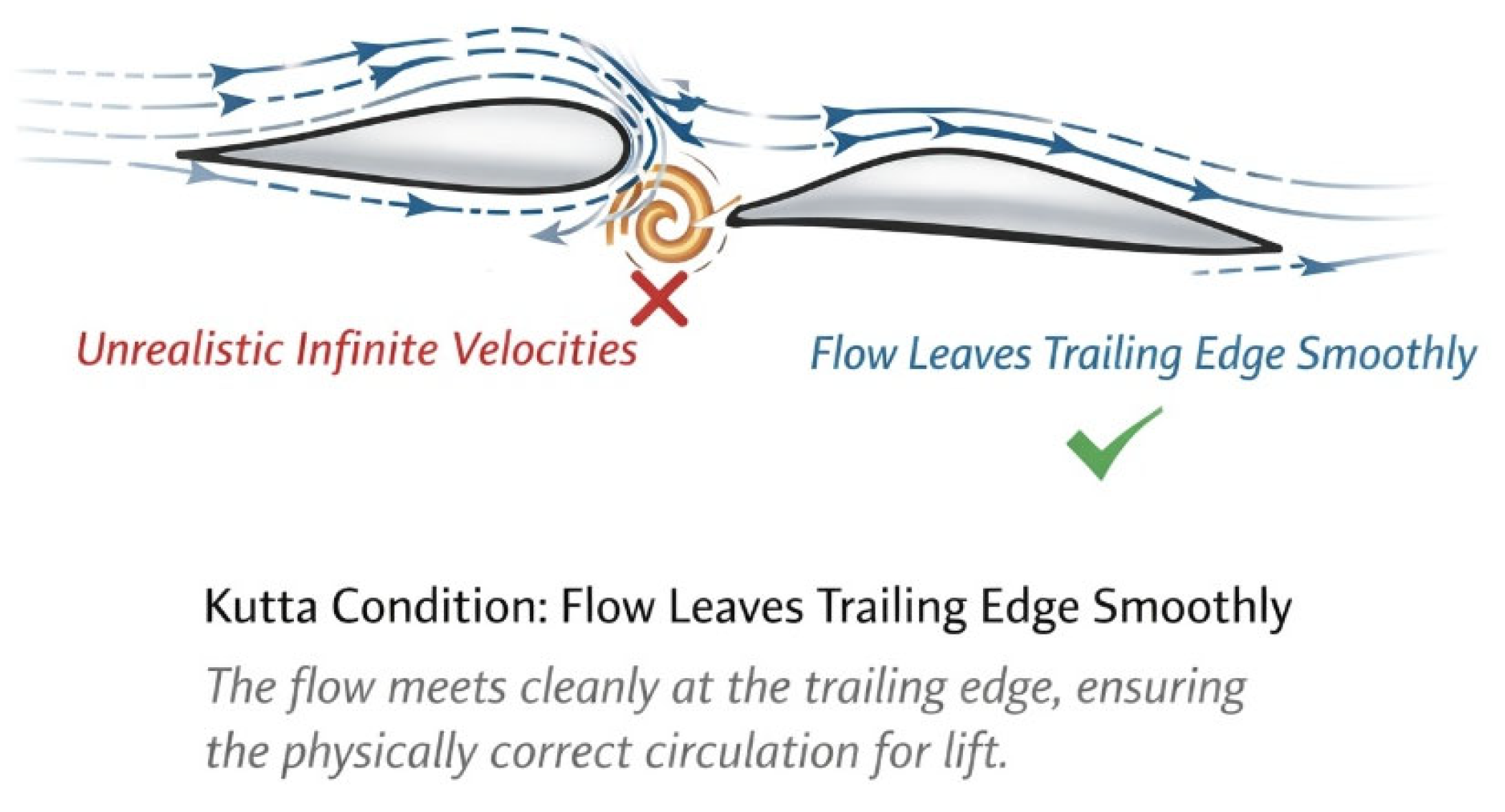
In Ideal inviscid flow, there are many possible ways the air could circulate around the wing. However, Kutta condition picks the real-life scenario and makes sure that the airflow leaves the trailing edge smoothly. This condition ensures that both upper and lower surface meet at the trailing edge. Therefore, unrealistic high velocities are avoided so the circulation is responsible for lift.
6.4. Physical Interpretation: Pressure Difference and Lift
Circulation is generated as a result of flow of air around the aerofoil. This circulation leads to make changes in the speed of the airflow on the upper and lower surface. Due to the shape of the wing the airflow passes faster over the upper section meanwhile it moves slower under the lower section. According to Bernoulli’s principle, , accordingly when there is higher velocity lower pressure exists and when there is lower velocity higher pressure exists. Therefore, the upper surface has lower pressure and the lower surface has higher pressure.
As a result of this pressure difference a net upward force is acted on the aerofoil. This is force generally acts perpendicular to free stream flow.
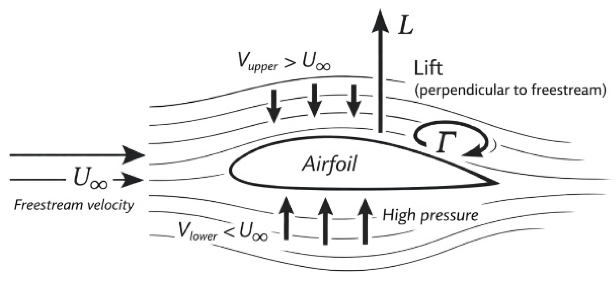
Instead of doing several calculations by using pressure at every point, a simple relationship given by Kutta-Joukowski theorem can be used to find the lift.
where,
= lift per unit span
= air density
= Freestream velocity
= Circulation
This equation shows that lift is directly proportional to circulation.
7. Thin Aerofoil Theory (TAT)
Thin Aerofoil Theory (TAT) is one of the most important basic theories in aerodynamics which helps us to understand how lift is created by an aerofoil using simplified mathematical model. Even though the behaviour of the real airflow around a wing is complex, this theory creates some reasonable assumptions so that we can get a clear relationship between angle of attack and lift generation.
This theory is valid only for the category of two-dimensional, symmetrical thin aerofoil at low angle of attack operating in incompressible and inviscid flow, The theory establishes a direct proportionality between lift coefficient and angle of attack.
where,
= angle of attack (radians), = lift coefficient
This describes that the lift increases proportionally with angle of attack forming basis of classical aerodynamic lift prediction. The gradient of the lift curve is: per radian.
The theory behind the lift is described by TAT relies on circulation (discussed earlier). Lift coefficient is predicted by TAT describes the relationship between AoA and circulation around the aerofoil. For symmetrical aerofoils lift is zero at zero AoA .
Under assumptions considered drag is zero. However, in the presence of viscous effects, pressure drag, and induced drag for finite wings, drag takes place.
8. Zero-Lift Angle of Attack in the Analysis of Lift and Drag
The angle of attack at which an aerofoil generates zero lift is known as the zero-lift angle of attack. It is denoted as . This parameter is a fundamental aerodynamic characteristic which is critical for understanding the lift behaviour of different aerofoil geometries. Mathematically, the zero-lift condition is expressed as = 0 when .
8.1. Influence of Aerofoil Geometry on Lift Behaviour
The value of is primarily relies on the geometry of the aerofoil; symmetry and the camber.
For symmetrical aerofoils, both the upper and lower surfaces are considered as identical to each other. When a symmetrical aerofoil is set to zero angle of attack the pressure distribution remains symmetrical and results a zero net lift.
. According to the thin aerofoil theory, . Therefore, the lift is directly proportional to angle of attack. This linear relationship form paves the path for analysing the variation of lift in a generic wing.
Cambered aerofoils produce lift even at zero geometric angle of attack due to their curved mean camber line. Consequently, the zero-lift condition occurs at a negative angle of attack:
< 0
As a result, the lift curve shifts leftward along the angle of attack axis.
Ex-
- NACA 2415 exhibits a zero-lift angle of approximately −2.0°.
- NACA 652-515 exhibits a zero-lift angle of approximately −3.0°.
Greater camber results a more negative zero-lift angle. This scenario confirms that camber directly affects the lift-angle relationship.
Thin aerofoil theory lays a strong theoretical foundation for estimating the zero-lift angle of attack, experimental investigations are slightly differed than theoretical predictions. Wind tunnel measurements conducted on several NACA aerofoils proves that theoretical estimations are not perfectly true when it comes to reality.
Ex-
- NACA 4-digit series, the experimentally determined zero-lift angle is approximately 0.93 times the theoretical value.
- NACA 230-series aerofoils, the experimental value is approximately 1.08 times the predicted theoretical result.
These deviations are arising as a result of phenomena such as viscosity, roughness of the surface, which are neglected by assumptions in theoretical calculations.
9. Finite Wing Correction: Lifting-Line Theory
The aerodynamic analysis based on thin aerofoil theory provides a strong theoretical foundation regarding the relationship between angle of attack and lift. However, this theory is only applicable under several assumptions: two-dimensional, infinite-span flow conditions are considered. But the real aircraft wing possesses finite span and it is three-dimensional. As a result of three-dimensional aerodynamic effects arise and influence both lift and drag.
In real wing air moves from the high-pressure region below the wing to the low-pressure region above the wing, this is caused as a result of velocity difference due to geometry of the wing. This creates trailing vortices behind the wing. A downward airflow called downwash, which reduces the effective angle of attack experienced by wing is resulted. As downwash reduces lift and increases drag, in reality a correction for finite span must be applied when analysing the effectivit of angle of attack to the aircraft lift.
Lifting-line theory, developed by Ludwig Prandtl provides basic mathematical framework related to aerodynamic performance of finite-span wing by applying corrections to two-dimensional aerofoil data. The theory simplifies the wing as a single line of circulation (vortex) along the span. The realistic spanwise lift distribution occurs as the circulation strength varies along this line. Ideal 2D theory is by connected with real world 3D wing behaviour by including the effect of trailing vorticities, lifting-line theory.
9.1. Correction to Lift-Curve Slope
Though the ideal 2D infinite wing span case, thin aerofoil theory predicts that lift increases linearly with angle of attack, due to the finite wing span of the real wing downwashes forms and reduces the effective angle of attack experienced by the wing. As a result of this, the rate at which lift increases with angle of attack becomes smaller compared to the ideal 2D case. As a further explanation, lift-curve slope of a finite wing is lower than that of an infinite aerofoil. Wings with high aspect ratios experience smaller reduction in lift slope while the wings with low aspect ratio experience greater reduction in lift slope. This happens because Lift distribution is not uniform along the span and energy is lost in the formation of trailing vortices.
| Aspect Ratio (AR) | Lift-Curve Behaviour | Induced Drag Behaviour | Overall Efficiency (L/D) |
| Low (AR ≈ 4) | Lift increases slowly with AoA | High induced drag | Lower efficiency |
| Moderate (AR ≈ 6) | Moderate lift increase | Moderate induced drag | Moderate efficiency |
| High (AR ≈ 10) | Lift increases more rapidly with AoA | Low induced drag | Higher efficiency |
The linear lift relationships which are derived from thin aerofoil and lifting-line theories are usually valid only within the range,
However, beyond this range boundary layer separation begins to develop, lift growth becomes nonlinear as well as inviscid assumptions break down.
10. Analytical Drag Modelling
10.1. Total Drag Decomposition
The total drag coefficient for a finite wing operating in steady incompressible flow, can be expressed as,
where, = induced drag coefficient, .
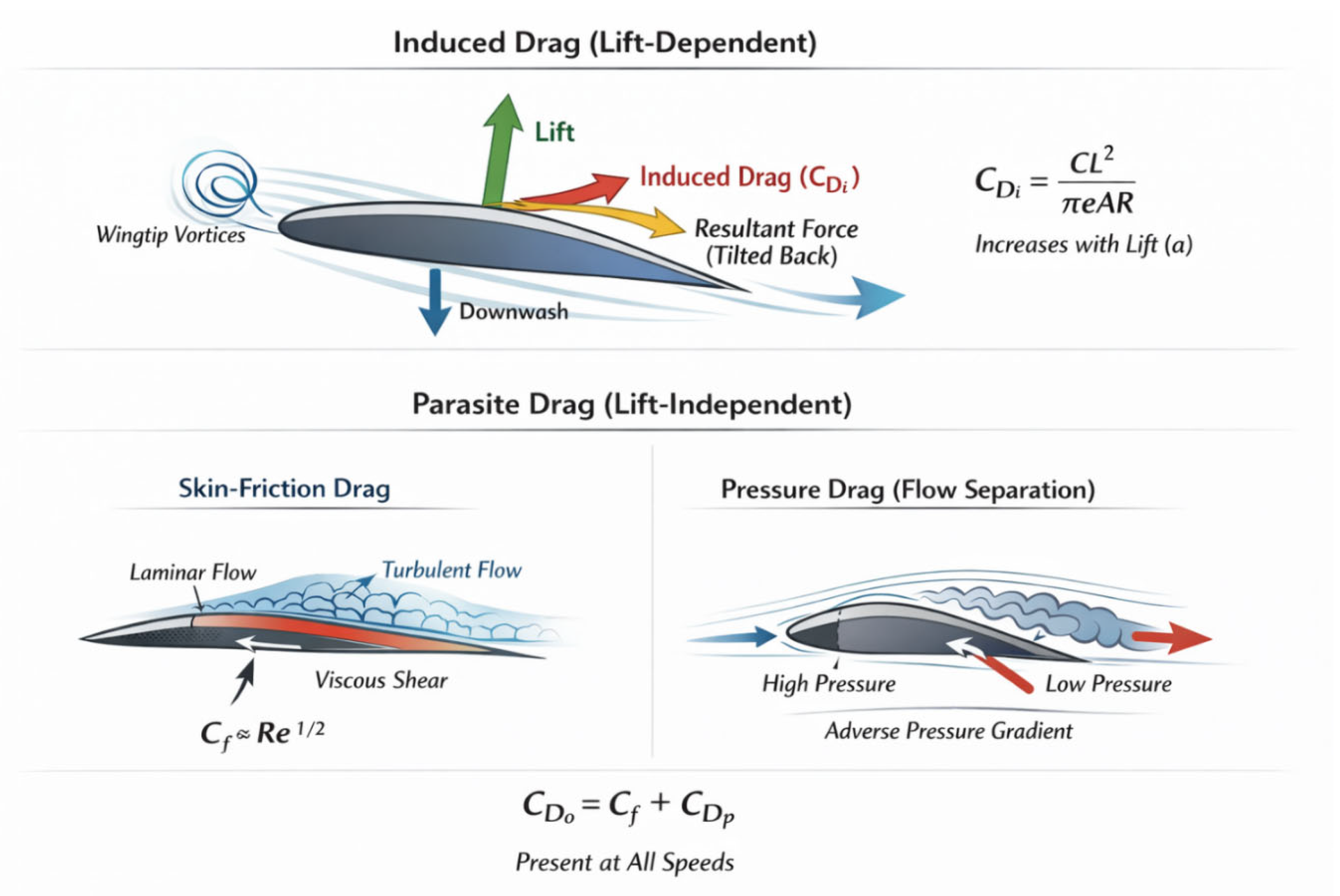
Induced drag cannot exist without lift production as it arises directly as a result of three-dimensional lift generating mechanism of a finite wing. Induced drag represents the aerodynamic cost of redirecting airflow downward to sustainable lift. On the other hand, parasite drag consists of all drag components including viscous skin friction drag and pressure drag resulted by the pressure different around the wing, that are not related to lift production in most cases. By separating total drag into induced drag and parasite components, it becomes easier to understand the effect of angle of attack in each mechanism individually. Furthermore, this separation improves theoretical modelling and allows to maintain accuracy of aerodynamic analysis under different flight conditions.
10.2. Induced Drag Modelling
Unlike two-dimensional aerofoil theory, which assumes infinite span; predicts zero drag in inviscid flow, the real aircraft wing is three-dimensional and consist of a finite wing-span. When it comes to reality the finite span allows pressure equalization near the wing tips, where the air from high pressure region moves towards the low-pressure region. Due to this span wise flow downwash condition is resulted (as mentioned earlier). The presence of downwash modifies the effective angle of attack experienced by the wing as follows, αeff=α−αi where the geometric angle of attack is denoted by , the induced angle of attack generated by the trailing vortex system is denoted by . As aerodynamic lift acts perpendicular to the local relative wing, this involves in changing the flow direction and slightly tilts the lift vector rearward. Then the tilted rearward lift vector takes place as a induced drag. This induced drag cannot exist in the absence of lift.
Lifting-line theory developed by Ludwig Prandtl gives the mathematical framework behind the induced drag. Induced drag coefficient for a finite wing operating in a steady, incompressible flow can be denoted as,
Where lift coefficient=, aspect ratio of the wing is AR and e is the Oswald efficiency factor. This indicates that induced drag increases when the square of lift coefficient increases and decreases when aspect ratio increases. As per thin aerofoil theory and lifting-line theory predictions lift increases linearly with angle of attack. As induced drag increases proportionally to , induced drag increases more rapidly. During the instances where lower flight speeds and maintained while higher lift coefficients are required (ex- during take-off and climb) induced drag forms a significant portion of the total drag.
Aspect ratio plays a vital role in determination of induced drag magnitudes. Usually wings with higher aspect ratio generate weaker trailing vorticities and experience reduced downwash effect. Basically, this principle supports to explain the aerodynamic efficiency of modern aircraft such as the Boeing 787 Dreamliner long-span and gliders which maintains high aspect ratio in order to optimize cruise performance. On other hand aircraft such as F-16 Fighting Falcon which are designed for high manoeuvrability and agility maintains a low aspect ratio in order to accept higher induced drag as part of their overall design requirement. As these calculations are reliable within the pre-stall region, this analytical model is mostly applicable within the moderate angle of attack.
10.3. Parasite Drag Modelling
Total aerodynamic resistance that does not directly involves in lift generation is defined as parasite drag. Unlike induced drag, which only exist only in the presence of lift, parasite drag appears whenever the object moves through the air. Therefore, parasite drag exists even if wing is not generating lift. Parasite drag consist of two main components: skin-friction drag and pressure (form) drag.
Skin-friction drag is caused as a result of viscosity of air. As air flows over the surface of the wing, boundary layer forms. Within the boundary layer region air velocity rapidly changes from zero at the surface to free stream velocity away from the surface. This velocity difference results shear stress along the surface, producing resistance known as skin-fiction drag. The smoother surface, lower the Skin-friction drag increases with AoA.while rough surface increases resistance. Pressure drags which is also know as form drag, arises as a result of difference of pressure around the wing. When the airflow remains attached to the surface at small to moderate angle of attack, pressure distribution is relatively streamlined and pressure drag remains limited. But when the angle of attack increases, boundary layer separation begins. However, this separation creates a low-pressure region behind the wing, and pressure drag increases. Near stall conditions rapid rise of pressure drag can be observed as large-scale flow separation takes place. Pressure drag will be the largest contributor to total aerodynamic resistance at near-stall condition. Unlike induced drag parasite drag is not directly depend on lift coefficient, however it primarily depends on flight speed and surface characteristics. In perspective of performance parasite drags dominates at high speeds (ex- cruise conditions, where lift requirement is comparatively less but high velocity is needed to be maintained.) Usually, Parasite drag becomes dominant at higher flight speeds, while induced drag dominates at low speeds where higher lift coefficients are required.
Therefore, proper understanding about induced drag and parasite drag is important for the aircraft performance.
10.4. Lift-to-Drag Ratio and Aerodynamic Efficiency
The lift-to-drag ratio one of the most key parameters used in aerodynamic efficiency evaluation of an aircraft, is commonly denoted as L/D. This represents the relationship between lift and drag. When L/D takes a higher value, it indicates that the aircraft is more efficient.
where =lift coefficient and is total drag coefficient. As mentioned in the section before drag has two main components; induced drag and parasite drag. The variation of L/D with the angle of attack depends on the combined behaviour of induced drag and parasite drag.
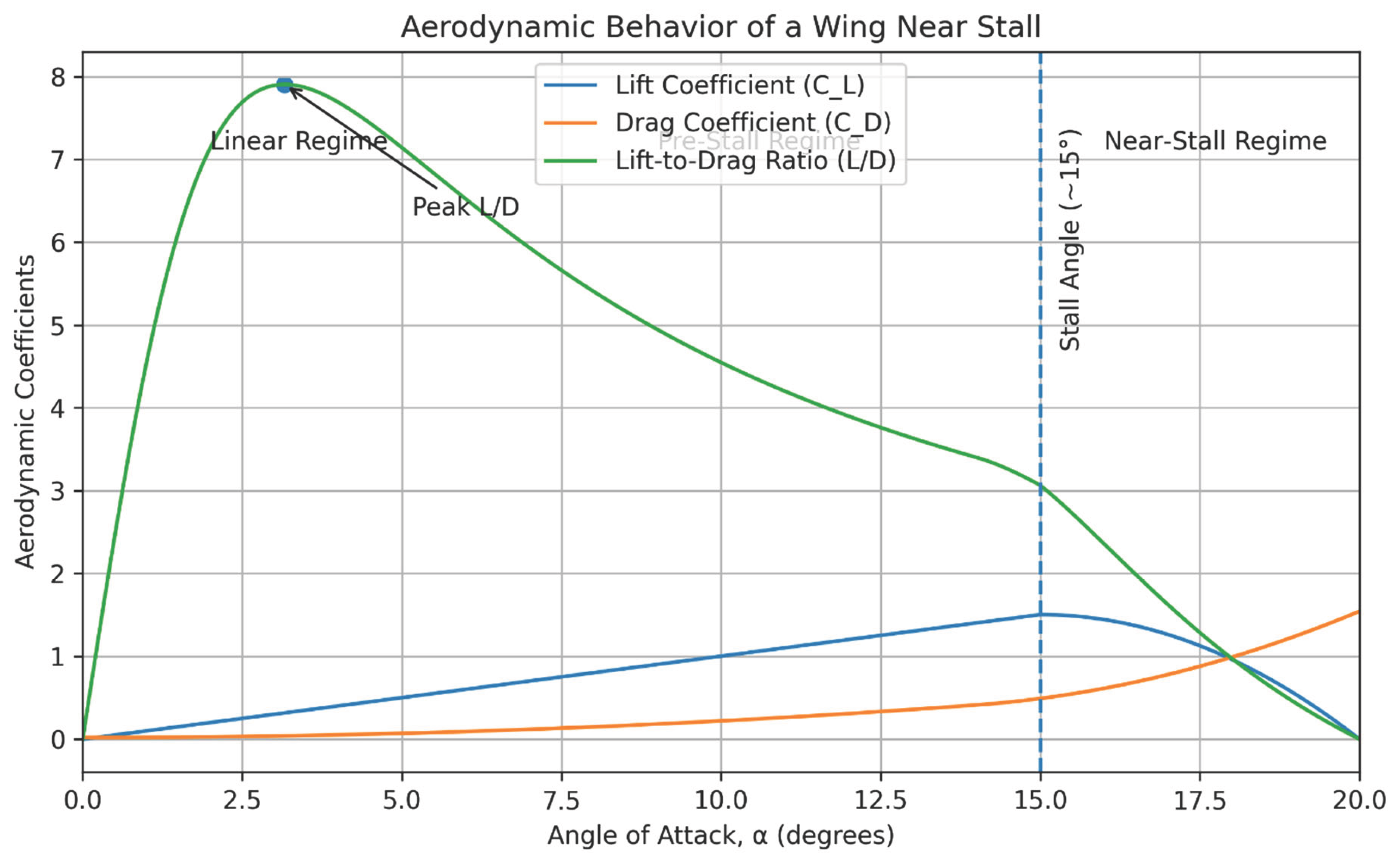
The lift coefficient is relatively low at low angle of attack. The lift coefficient increases approximately proportionally as the angle of attack increases within the linear region. Within this region lift rises more rapidly than total drag. This results an improvement in lift-to-drag ratio. As induced drag strongly depends on lift, induced drag grows rapidly when the angle of attack is increased. Total drag begins to rise faster than lift. Near the stall region as airflow begins to separate, extra pressure drag is created and the total drag sharply increases. As a result of increment in drag faster than the lift at high angle of attack, L/D drops. However continuous increment in L/D cannot be seen, L/D rises to a peak and then descends. The angle at which the highest point occurs denotes the aerodynamically most efficient operating point. At this point greatest lift for the least amount of drag is generated. Studying about this angle is important, as it allows the aircraft to travel the far most distance for given amount of energy.
Geometry of the wing is crucial for determining the magnitude of the maximum L/D. Wings with high aspect ratio (long, slender wings) reduce induced drag and improve aerodynamic efficiency. This philosophy is specially used in gliders, and modern jets which are designed to maintain fuel efficiency (ex- Boeing 787 Dreamliner). However, fighter jets such as F-16 Fighting Falcon have wings with lower aspect ratio as they were designed by focusing: manoeuvrability, roll rate and structural strength.
| AoA Regime | Flow Condition | Lift Behaviour | Drag Behaviour | L/D Behaviour |
| Linear Attached-Flow | Boundary layer fully attached | Lift rises linearly | Drag rises gradually | L/D steadily increases |
| Nonlinear Transition | Partial flow separation near trailing edge | Lift growth slows | Drag rises faster | L/D reaches peak (optimal AoA) |
| Near-Stall | Large-scale flow separation | Lift decreases | Drag rises sharply | L/D drops rapidly |
The analysis of lifts to drag ratio (L/D) is crucial to improve the fuel efficiency of the aircraft, and to optimise the aerodynamic efficiency of the aircraft.
11. Angle of Attack Regimes
The aerodynamic characteristics of an aircraft wing vary with the angle of attack. When the angle increases, the flow field around the wing shows several variations which significantly influence lift generation, drag characteristics and overall aerodynamic efficiency. For the clarity of analysis, the aerodynamic response can be categorized into three main regimes: the linear attached-flow regime, the nonlinear transition regime, and the near-stall regime.
11.1. Linear Attached Flow
Airflow remains fully attached to the surface of the wing at relatively small angles of attack. In normal conditions during this region pressure distribution over the aircraft’s wing remains stable meanwhile boundary layer flows without separation. Lift coefficient rises linearly with the angle of attack. Basically, these conditions are closely aligning with lifting-line theory predictions and predictions from thin aerofoil theory. As the combination of parasite drag and induced drag are directly affected by lift, total drag gradually increases with the lift production. With this region as lift shows a rapid increment than the drag, L/D ratio increases steadily.
11.2. Nonlinear Region and Near-Stall Regime
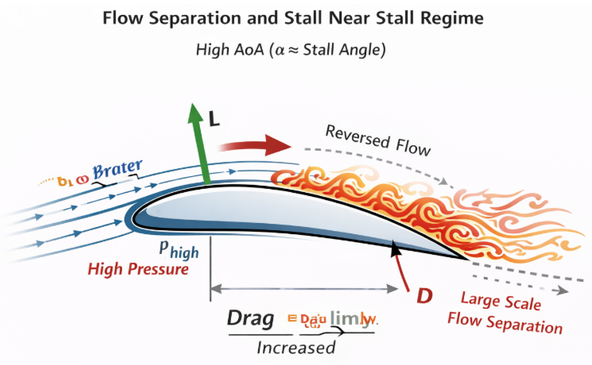
When the angle of attack increases further, boundary layer becomes thicker and flow separation begins to develop in localized regions because of inability of boundary layer to overcome oppose pressure resulted by thickening of boundary layer and the force given by the reversed flow. This flow separation initiates closer to the trailing edge and moves towards the leading edge. This separation of flow modifies the pressure distribution as well as reduce effectiveness of lift generation. The rate at which lift grows begins to slow down while the angle of attack increases. Due loss of pressure drags rises. Within this region the L/D ratio reaches o its peak, which denotes the most aerodynamically efficient condition.
At high angle of attack flow separation occurs in large scale manner, and separation spreads over a large area of the aerodynamic surface. After a certain level aerodynamic characteristics of the wing starts to deteriorate. Lift coefficient reaches to the maximum level which, it can reach and decreases when Angle of Attack further increases. As flow separation takes place in high scale, pressure drag increases by resulting, a sharp rise in drag. However, due to the increment of drag and reduction of lift, L/D rapidly decreases. This leads to reduce aerodynamic efficiency of the wing.
In order to maintain the controllability and prevent stall pilots must avoid exceeding critical angle of attack. However modern-day engineers are trying to delay the stall, by applying some design strategies such as wing twist, leading edge device or high lift aerofoils.
12. Discussion
The discussion about lift and drag analysis with respect to Angle of Attack is basically based on fundamental relationship between aerodynamic forces and wing geometry. Theoretical models such as Thin Aerofoil Theory (TAT) and Lifting-Line Theory, give simplified frameworks to predict lift generation and drag characteristics of a generic wing under several assumptions. These models further demonstrate that; during pre-stall range, lift increases linearly with Angle of attack and drag rises gradually due to both parasite and induced components. However purely viscous model fails to maintain its validity, especially after boundary layer separation begins since real world conditions such as viscous effects, boundary-layer development, flow separation, and stall phenomena influences on the performance of the aerodynamic surface and increases the complexity.
Real-Life Applications of AoA, Lift, and Drag
Modern aircraft engineering systems demonstrate how these theoretical predictions are applicable in real-world scenarios.
During take-off and landing commercial airliners such as Boeing 737 operate at relatively higher angle of attack as its requirement of generation of lift at lower speed. Meanwhile devices such as flaps and slats are used to further enhance the lift by increasing the drag. However, during cruise flights usually maintain moderate angle of attack in order to optimize the aerodynamic performance as well as maintain the fuel efficiency.
Gliders such as Schleicher ASW 27 almost relies on aerodynamic performance rather than engine thrust. Therefore, gliders mostly operate close to their optimal aerodynamic efficiency. However, even a small variation in Angle of Attack could affect the glide performance. These gliders consist of long wings with high aspect ratio in order to minimize the induced drag to maintain its efficiency.
However, Fighter jets are designed for a different purpose than commercial aircraft. So, fighter jets such as F-16 Fighting Falcon frequently operates at higher angle of attack during combat to achieve greater lift capability and enhance agility. While this increases lift for manoeuvring and also increases induced drag, demonstrating functional difference between commercial aircraft which focused on efficiencies and fighter jets made for manoeuvrability.
Meanwhile aircraft like Grumman F-14 Tomcat consist of variable-sweep wings, allows to optimize the aircraft performance under different criteria. During take-off and landing the aircraft extends its wings forward approximately 20° , which leads to increase its lift at high angle of attack. And during cruise wings sweep back to approximately 35–45° resulting, reduction in drag and improving aerodynamic efficiency. This ability of the aircraft allows it to maintain aerodynamic efficiency, Aswell as combat features.
| Aircraft/System | Flight Phase | AoA Behavior | Lift Characteristics | Drag Characteristics | Efficiency Notes |
| Boeing 737 | Takeoff / Landing | High AoA | Lift increased with flaps | Drag increases | Moderate efficiency |
| Boeing 737 | Cruise | Moderate AoA | Stable lift | Moderate drag | High efficiency |
| Schleicher ASW 27 | Soaring | Low–Moderate AoA | Efficient lift generation | Very low drag | Maximum efficiency |
| F-16 Fighting Falcon | Combat Manoeuvre | High AoA | High lift for turning | High induced drag | Manoeuvrability prioritized |
| F-14 Tomcat | Takeoff/Landing (20° sweep) | Higher AoA | High lift | High drag | Moderate efficiency |
| F-14 Tomcat | Cruise (35–45° sweep) | Moderate AoA | Balanced lift | Reduced drag | High efficiency |
| F-14 Tomcat | Supersonic (60–68° sweep) | Lower AoA | Reduced but sufficient lift | Minimal drag | Optimized for speed |
| Wind Turbine | Energy Generation | Controlled by pitch | Lift drives blade rotation | Drag minimized | High aerodynamic efficiency |
13. Conclusions
During this study the effect of angle of attack (AoA) on lift, drag and aerodynamic efficiency are examined. The study demonstrates that within the linear Angle of attack range, lift increases proportionally with angle of attack while drag rises gradually. During this regime a steady lift to drag ratio is maintained. When angle of attack further increases and came up to pre-stall regime, partial flow separation reduces rise of lift and increases drag, forming a peak in L/D. This point is the most aerodynamically efficient instance. During the near stall region flow separation occurs in higher scale causing rapid decrease in lift and a sharp rise in drag. This reduces aerodynamic efficiency.
Theoretical models such as Thin Aerofoil Theory and Lifting-Line Theory provide a solid foundation for the study on aerodynamic performance. However, when it comes to reality some deviations occur due to real world conditions such as viscous effects, boundary-layer growth, and flow separation. Furthermore the study highlights some features in aerodynamic design such as effective Angle of Attack management, aspect ratio, camber, and sweep angle.
Modern aerodynamic design relies on hybrid approaches; integration of classical theoretical models with CFD simulations and wind-tunnel testing. This allows engineers to maintain simplicity and accuracy. However, understanding the complex interaction between Angle of Attack, lift generation, drag forces, and wing geometry is crucial for improving aerodynamic efficiency, developing safety features.
References
- Abbott, I.H.; von Doenhoff, A.E. Theory of Wing Sections: Including a Summary of Airfoil Data; Dover Publications: New York, NY, USA, 1959. [Google Scholar] [CrossRef]
- Anderson, J.D. Fundamentals of Aerodynamics, 6th ed.; McGraw-Hill Education: New York, NY, USA, 2017. [Google Scholar] [CrossRef]
- Prandtl, L. Applications of Modern Hydrodynamics to Aeronautics. NACA Report 1921, 116, 1–44. [Google Scholar]
- Jacobs, E.N.; Ward, K.E.; Pinkerton, R.M. The Characteristics of 78 Related Airfoil Sections from Tests in the Variable-Density Wind Tunnel. NACA Technical Report 1933, 460, 1–300. [Google Scholar]
- Glauert, H. The Elements of Aerofoil and Airscrew Theory; Cambridge University Press: Cambridge, UK, 1926. [Google Scholar] [CrossRef]
- Schlichting, H.; Gersten, K. Boundary-Layer Theory, 9th ed.; Springer: Berlin, Germany, 2017. [Google Scholar] [CrossRef]
- Katz, J.; Plotkin, A. Low-Speed Aerodynamics, 2nd ed.; Cambridge University Press: Cambridge, UK, 2001. [Google Scholar] [CrossRef]
- NASA Glenn Research Center. Beginner’s Guide to Aerodynamics . Available online: https://www.grc.nasa.gov/www/k-12/airplane/bga.html (accessed on 7 March 2026).
- Drela, M. XFOIL: An Analysis and Design System for Low Reynolds Number Airfoils; Massachusetts Institute of Technology: Cambridge, MA, USA; Available online: https://web.mit.edu/drela/Public/web/xfoil/ (accessed on 7 March 2026).
- Kutta–Joukowski Theorem. Available online: https://en.wikipedia.org/wiki/Kutta%E2%80%93Joukowski_theorem (accessed on 7 March 2026).
Disclaimer/Publisher’s Note: The statements, opinions and data contained in all publications are solely those of the individual author(s) and contributor(s) and not of MDPI and/or the editor(s). MDPI and/or the editor(s) disclaim responsibility for any injury to people or property resulting from any ideas, methods, instructions or products referred to in the content. |
© 2026 by the authors. Licensee MDPI, Basel, Switzerland. This article is an open access article distributed under the terms and conditions of the Creative Commons Attribution (CC BY) license (http://creativecommons.org/licenses/by/4.0/).
Copyright: This open access article is published under a Creative Commons CC BY 4.0 license, which permit the free download, distribution, and reuse, provided that the author and preprint are cited in any reuse.