
Submitted:
24 February 2026
Posted:
27 February 2026
You are already at the latest version
Abstract
This study focuses on the aerodynamic performance optimisation of the SG6043 airfoil for application in small horizontal axis wind turbines (HAWTs) operating under low Reynolds number conditions. Recognizing the critical role of lift-to-drag ratio (CL/CD ) in maximizing turbine power output. The research investigates the performance of SG6043 through design modifications and computational analysis. Initially, the baseline airfoil's aerodynamic characteristics were verified using simulation tools like QBlade software, confirming its previously reported performance. Subsequently, the airfoil was systematically modified by varying key parameters including thickness-to-camber ratio, angle of attack (AOA), operating at different Reynolds numbers. Among the modified versions, SG6043M5-7, SG6043M5-8, and SG6043M5-9 showed significant aerodynamic performance improvement, with SG6042M5-9 achieving the highest CL/CD ratio of 193.44 at Re = 6×10⁵ and AOA = 3.5°. The results demonstrated that a reduced thickness (5%) combined with moderate to high camber (7–9%) enhances the aerodynamic performance.
Keywords:
SG6043 airfoil
; low Reynolds number
; small horizontal axis wind turbine (HAWT)
; QBlade
; aerodynamic performance
1. Introduction
1.1. Background and Motivation
Wind energy has emerged as one of the most significant renewable resources globally, offering clean and sustainable power generation for both large-scale utility applications and small-scale distributed systems. According to the REN21 Global Status Report 2023 and the IEA World Energy Outlook 2023, global wind power capacity has seen substantial growth, with small wind turbine installations expanding significantly to meet the needs of off-grid and distributed generation applications. Small Horizontal Axis Wind Turbines (HAWTs) play a crucial role in this landscape, particularly in rural and remote areas where grid connectivity is limited or unreliable. However, while wind energy offers immense potential, it has variable availability due to meteorological conditions, necessitating highly efficient conversion systems to maximise energy capture during operational windows.
The aerodynamic performance of these smaller turbines is significantly constrained by their operation at low Reynolds numbers (typically ). In this regime, flow characteristics differ substantially from those encountered in large-scale utility turbines. The Betz coefficient establishes a theoretical maximum efficiency of 59.3% for wind energy extraction (Betz, 1966), but practical limitations—particularly laminar separation bubbles and early transition phenomena—result in much lower actual efficiencies for small turbines. Consequently, the design of airfoils that must perform efficiently under these challenging conditions is a critical area of research.
1.2. Low Reynolds Number Aerodynamics and Literature Review
At low Reynolds numbers, airfoil performance is characterised by complex flow phenomena, including laminar boundary layer separation, reattachment, and increased sensitivity to surface roughness (Drela, 1989, Miley, 1982). These factors often lead to a drastic reduction in lift-to-drag ratios compared to high Reynolds number conditions. Extensive research has been conducted to address these challenges. Giguère and Selig (1998), Giguère and Selig (1997) Selig and McGranahan (2004) conducted comprehensive wind tunnel testing of the SG6040-SG6043 airfoil series, where the SG6043 emerged as the most efficient, achieving a maximum of 125 at .
Recent computational studies have further validated the SG6043’s potential. Suresh and Rajakumar (2019) analysed ten airfoils using QBlade software, while Alaskari et al. (2019) confirmed SG6043’s optimal performance at low angles of attack. Building on this, researchers have attempted to optimise the SG6043 through various geometric modifications. Osei and et al. (2020) developed three modified variants (EYO7-8 to EYO9-8), achieving maximum ratios up to 170. More recently, Seifi Davari et al. (2025) optimised the thickness-to-camber ratio, achieving a maximum ratio of 184.85. A summary of key historical and recent contributions is provided in Table 1.
1.3. Research Gap
The literature indicates that numerous studies have focused on designing airfoils for low Reynolds number Small Horizontal Axis Wind Turbines (HAWTs). A key challenge is selecting and optimizing an airfoil that achieves a high lift-to-drag ratio while maintaining stable performance under varying conditions, including thickness-to-camber ratio, angle of attack (AOA), and Reynolds number. This study aims to modify and optimize the SG6043 airfoil by examining the effects of thickness-to-camber ratio, AOA, and Reynolds number, and to evaluate the performance of the optimized design in a HAWT rotor. The research provides a comprehensive foundation for developing and implementing optimized SG6043 airfoils in small wind turbine applications, contributing to the advancement of efficient renewable energy technologies.
2. Methodology
2.1. Airfoil Selection and Computational Tool
A comprehensive literature review of 30 high-performance low Reynolds number airfoils was conducted. Based on criteria focusing on maximum ratios and stability, the SG6043 airfoil was selected as the baseline candidate (Miley, 1982, Wata et al., 2011, Singh et al., 2012).
QBlade (open-source, version 0.96) was used for all airfoil design and simulation tasks in this study. QBlade employs the XFOIL (version 6.99) solver backend for aerodynamic analysis (Drela, 1989). QBlade was selected for its proven accuracy in low Reynolds number regimes and its widespread acceptance in wind energy research (Alaskari et al., 2019, Said et al., 2019, Prakash et al., 2020). The thickness-to-camber ratio (t/c) has a significant influence on the aerodynamic performance and lift-to-drag ratio of an airfoil. Increasing camber generally enhances lift generation at low Reynolds numbers by strengthening the favorable pressure gradient on the suction surface, whereas excessive camber can cause early flow separation and increase drag. Similarly, a moderate thickness improves structural strength and delays stall by maintaining smoother pressure recovery, but overly thick profiles increase pressure drag and reduce aerodynamic efficiency. Therefore, an optimal balance between thickness and camber is required, as airfoils with a well-tuned t/c ratio typically achieve higher lift-to-drag performance across a wider operating range.
2.2. Design Modification
The SG6043 airfoil have been parametrically modified to improve its aerodynamic efficiency. The modification process involved the variation of parameters; thickness-to-camber ratio, angle of attack (AoA) and Reynolds Number. Each parameter has been varied individually to study its effect on the airfoil’s performance. The design has been iteratively optimized based on simulation results, aiming to maximize the lift-to-drag ratio while ensuring aerodynamic stability. The simulations and performance evaluation have been performed using Q-Blade, which is open source too widely used for airfoil design and analysis.
2.3. Computational Assumptions and Boundary Conditions
To ensure reproducibility and clarity, the following computational assumptions and boundary conditions were applied to all simulations:
- Flow Regime: The flow is assumed to be steady, incompressible, and two-dimensional.
- Turbulence Model: The method was used for transition prediction, with a critical amplification factor () of 9, representing standard clean wind tunnel conditions.
- Operating Conditions: Reynolds number () and Angle of Attack () are treated as operating conditions. The study covers to and to (in increments).
- Design Parameters: Airfoil Maximum Thickness () and Maximum Camber are treated as the geometric design parameters.
-
Boundary Conditions:
- ▪
- Inlet: Uniform freestream velocity corresponding to the specified Reynolds number.
- ▪
- Outlet: Pressure outlet with zero gradient conditions.
- ▪
- Surface: No-slip boundary condition on the airfoil surface.
2.4. Validation Protocol
Baseline SG6043 performance was first validated against published XFOIL and experimental data from (Giguère and Selig, 1998), followed by parametric modifications. The validation process compared the ratios and stall angles, showing a maximum deviation of across the tested Reynolds number range, which falls within acceptable limits for computational aerodynamic studies.
2.5. Parametric Optimisation Strategy
The SG6043 airfoil was systematically modified to explore the design space. The modification process involved:
- Thickness Variation: Reduced from the original 10% to a range of 5–9% (in 1% increments).
- Camber Variation: Adjusted from the original 5.1% to a range of 5–9% (in 1% increments).
- Combinatorial Analysis: A total of 25 distinct geometric combinations were generated and simulated across all six Reynolds numbers.
Uncertainty quantification was performed by varying (7–11) and grid density, yielding a total computational uncertainty of approximately .
3. Results and Discussion
All aerodynamic coefficients presented in this section were computed using QBlade’s XFOIL-based solver under the conditions specified in Section 2.
3.1. Initial Screening and Baseline Performance
The comparative evaluation of thirty low-Reynolds-number airfoils conducted in previous studies (Miley, 1982; Wata et al., 2011; Shah et al., 2012; Singh et al., 2012; Shah et al., 2014) consistently identified the SG6043 as the strongest baseline performer for small wind turbine applications. As shown in Figure 1(a) and Figure 1(b), the performance hierarchy clearly positions SG6043 above the other assessed profiles. Its aerodynamic advantage is highlighted by a maximum lift-to-drag ratio (CL/CD) of 152.88 achieved at a Reynolds number of 6×10⁵, demonstrating excellent efficiency in low-to-moderate wind-speed conditions. This peak value indicates a favorable combination of delayed stall, low profile drag, and high lift generation, making the SG6043 airfoil a robust and reliable reference for further optimization and modification studies.
Figure 1.
CL/CD vs AOA of high-performance low Reynolds number airfoils (Re=6x10⁵ ).
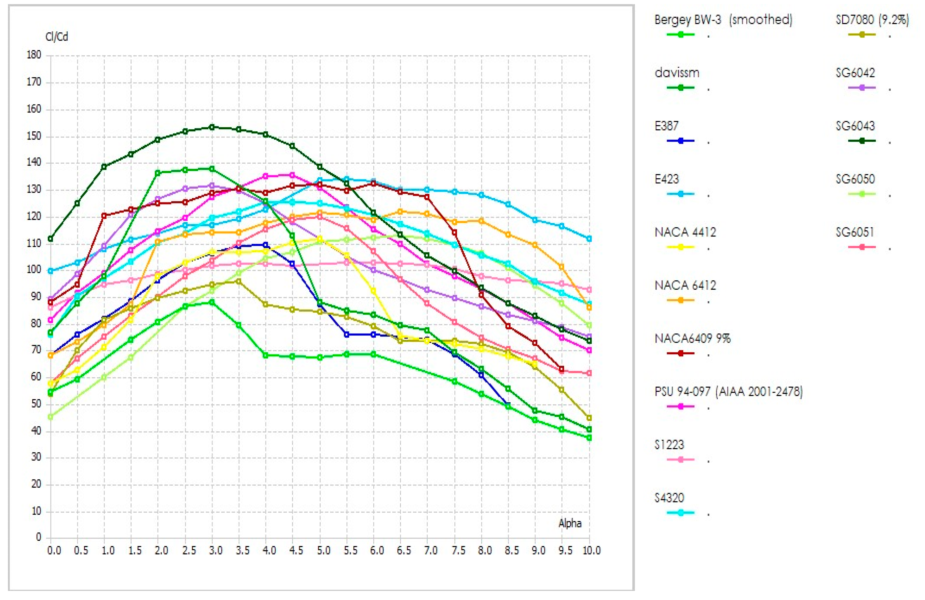
Figure 2.
CL/CD vs AOA of high-performance low Reynolds number airfoils(Re=6x10⁵ ).

The baseline SG6043 has a thickness of 10% and a camber of 5.1%, as shown in Figure 3. Its performance, measured by the lift-to-drag ratio (CL/CD), improves with increasing Reynolds number (Figure 4). This trend occurs because at low Reynolds numbers, the airflow over the airfoil is mostly laminar and very sensitive to surface geometry. The relatively thick 10% profile can create stronger adverse pressure gradients, which can cause early separation of the laminar boundary layer and form small “laminar separation bubbles,” reducing lift and increasing drag. As the Reynolds number increases, the boundary layer gains more momentum, making it more resistant to separation, which explains why the lift-to-drag ratio improves at higher Re.
Similarly, the camber of 5.1% helps generate lift by creating a favorable pressure difference along the upper surface. However, excessive camber can also intensify the suction peak, which may trigger early laminar separation at low Reynolds numbers. In the SG6043 baseline, the combination of moderate thickness and camber allows the boundary layer to transition gradually from laminar to turbulent flow, helping maintain lift while limiting drag across the studied Reynolds number range.
The computational validation against published XFOIL data (Figure 5 and Table 2) confirms that the QBlade simulations capture these physical behaviors accurately, showing excellent agreement in CL/CD trends across different Reynolds numbers.
Figure 3.
Selected Airfoil SG6043.
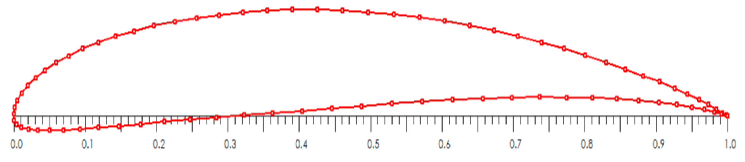
Figure 4.
Shows lift to drag ratio of selected Airfoil SG6043 at Re. 1x10⁵ to 6x10⁵.
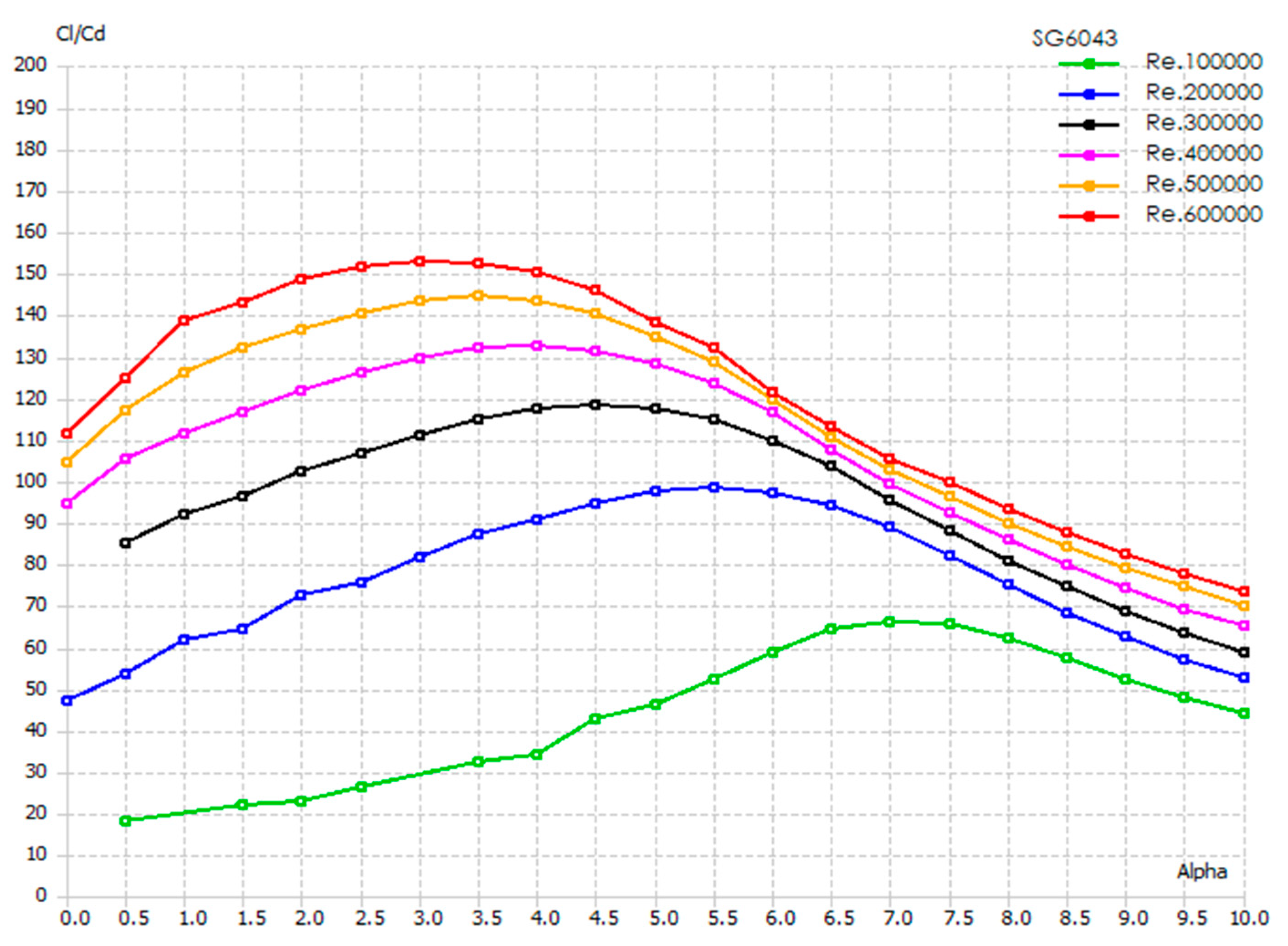
Figure 4 reflect the aerodynamic performance of the base airfoil SG6043 at low Reynolds numbers ranging from 1×10⁵ to 6×10⁵. The data shows that as Reynolds number increases, the lift-to-drag ratio (C L /C D ) improves considerably; which is 152.88 at Reynolds number 6×10⁵ and angle of attack 3°. The SG6043 airfoil performs most efficiently with increasing Reynolds number and moderate angles of attack.
Figure 5.
Validation of reported XFOIL performance of SG6043 with Q-Blade.
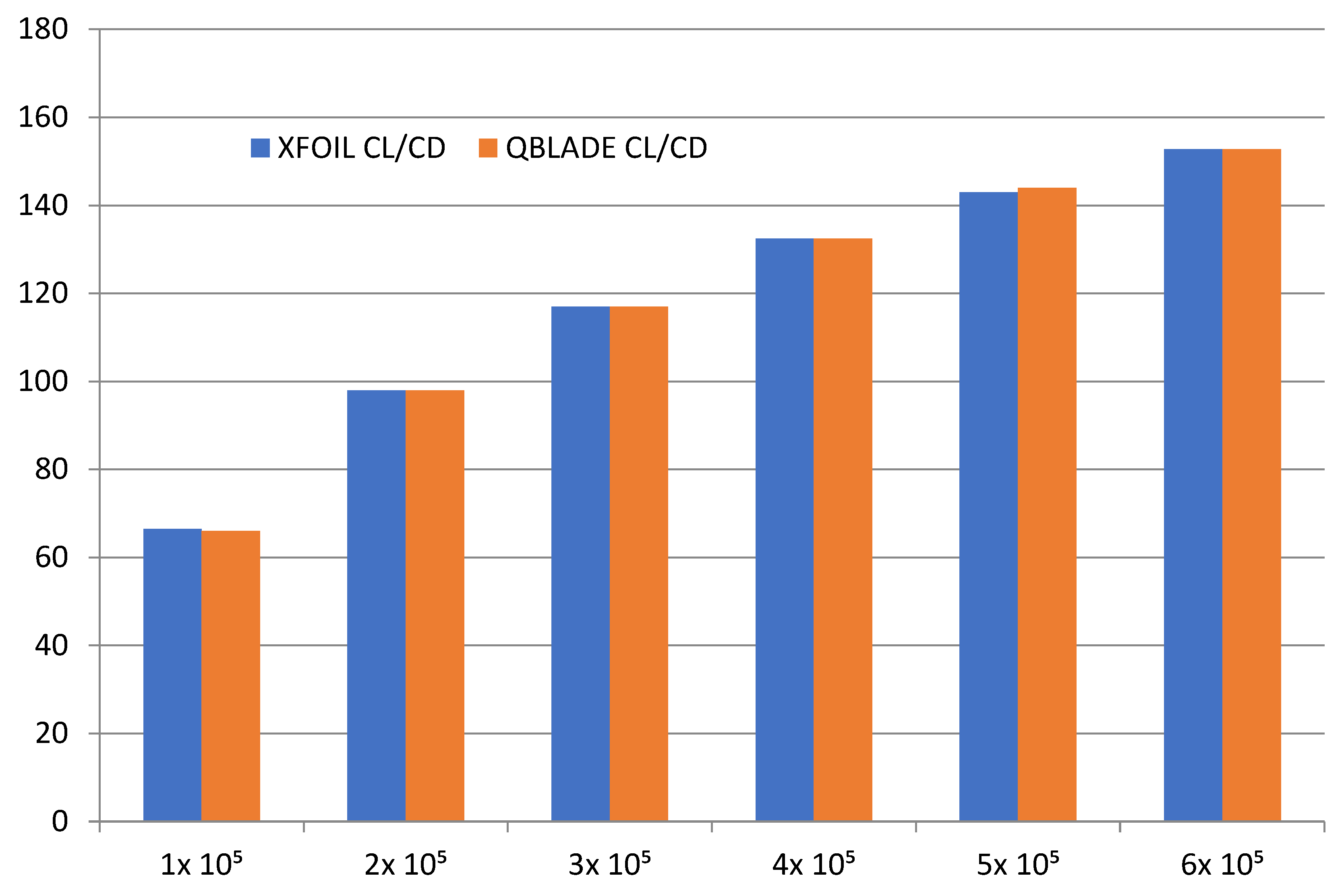
Figure 5 show the comparison of the maximum lift-to-drag ratio (C L /C D ) and corresponding angle of attack (AOA) for the SG6043 airfoil at various Reynolds numbers obtained through XFOIL and Q-Blade. It verifies that the performance of the SG6043 airfoil through Q-Blade and XFOIL is consistent with available data.
3.2. Optimisation Results and Design Space Exploration
The systematic sweep of 25 modifications revealed distinct performance trends. QBlade simulation results indicate that a thickness of 5% consistently yields the highest aerodynamic efficiency across the studied Reynolds numbers. However, the optimal camber varies with flow regime.
Table 3 summarizes the peak performance of the three identified optimal variants. Values represent the maximum attainable efficiency at the specified Reynolds number and its corresponding optimal Angle of Attack (AOA).
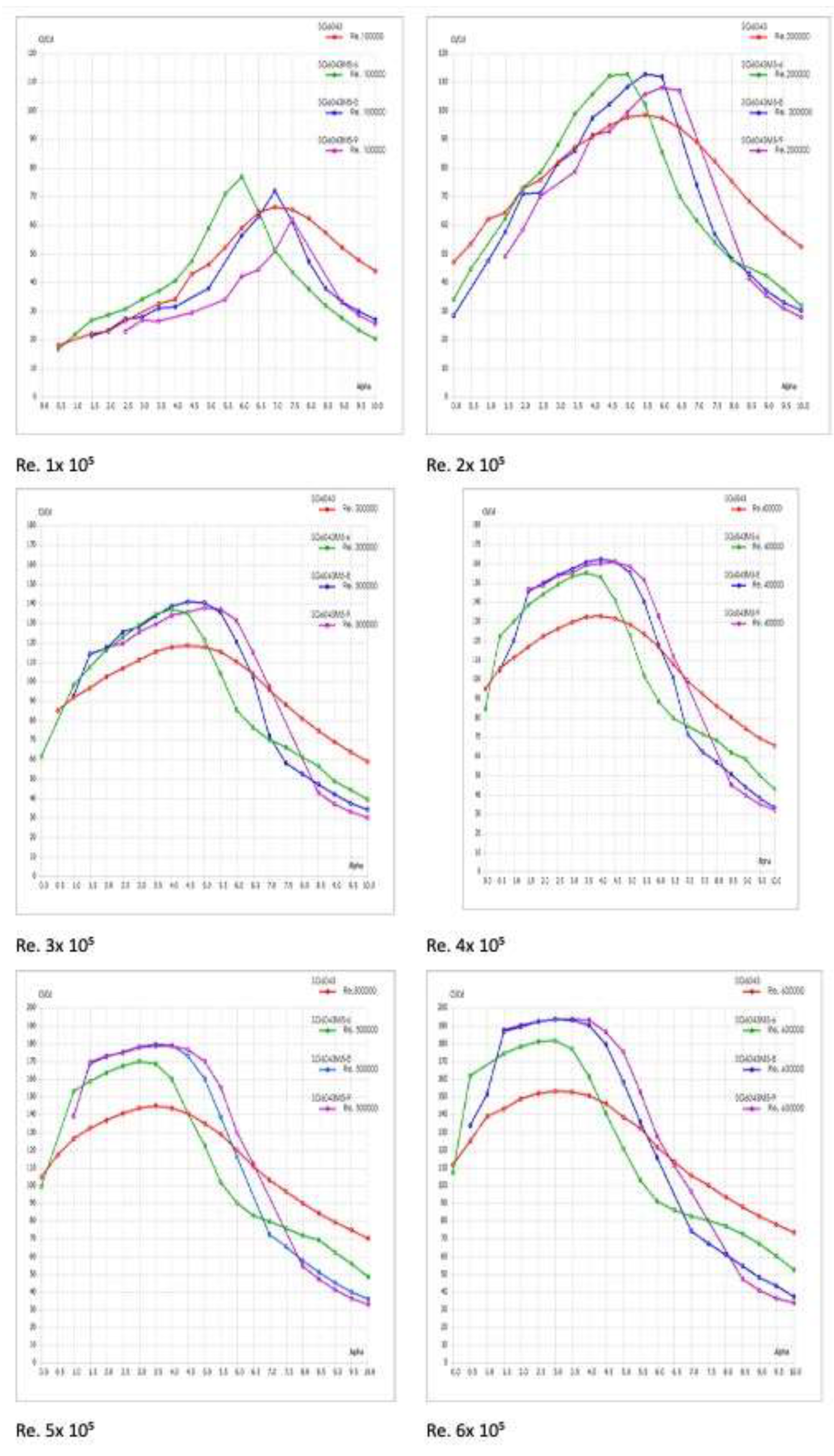
The geometric profiles of the high-performing modified airfoils are illustrated in Figure 6, showing the systematic variation in thickness and camber distributions. The comprehensive performance analysis of all 25 modifications across the six Reynolds numbers is presented in Figure 7, which displays the lift-to-drag ratio curves with uncertainty bounds, revealing the performance landscape of the design space. Figure 8 focuses specifically on the three optimal variants (SG6043M5-6, SG6043M5-8, and SG6043M5-9), providing a detailed comparison of their aerodynamic characteristics across different Reynolds numbers with uncertainty quantification.
QBlade analysis shows that at lower Reynolds numbers (), the SG6043M5-6 (6% camber) outperforms other variants. The reduced camber minimizes adverse pressure gradients, maintaining laminar flow stability. Conversely, at higher Reynolds numbers (), the SG6043M5-9 (9% camber) exploits the higher momentum boundary layer to support greater lift, achieving a peak of 193.44. The SG6043M5-8 serves as an excellent mid-range performer, offering versatility across .
Figure 7.
CL/CD vs AOA of all modified airfoils at different Reynolds numbers with uncertainty bounds (Re= 1x10⁵ to 6x10⁵).
Figure 7.
CL/CD vs AOA of all modified airfoils at different Reynolds numbers with uncertainty bounds (Re= 1x10⁵ to 6x10⁵).
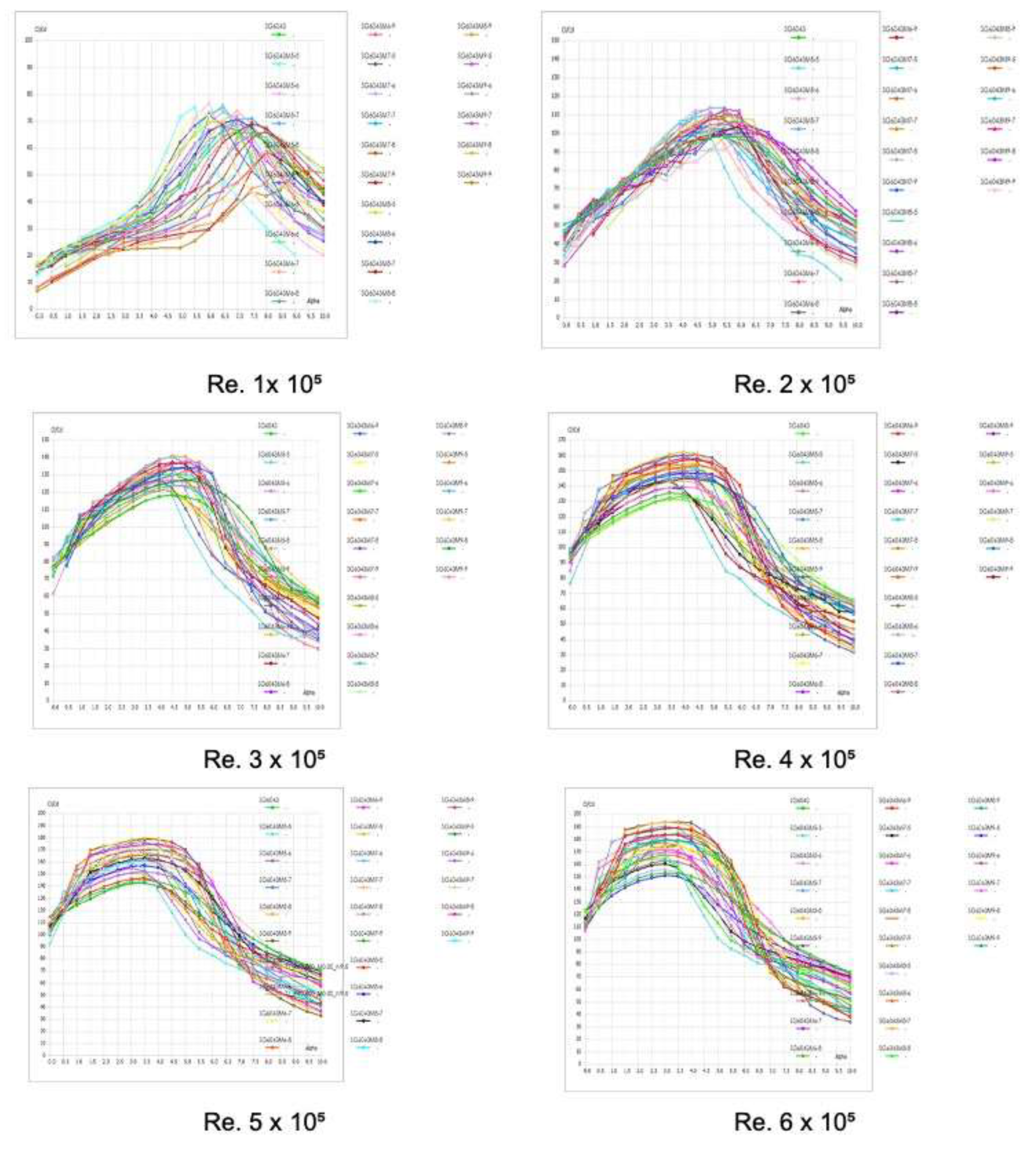
Figure 8.
CL/CD vs AOA of optimized SG6043 variants (SG6043M5-6, SG6043M5-8, and SG6043M5-9) at different Reynolds numbers with uncertainty bounds.
Figure 8.
CL/CD vs AOA of optimized SG6043 variants (SG6043M5-6, SG6043M5-8, and SG6043M5-9) at different Reynolds numbers with uncertainty bounds.
3.3. Comparative Analysis
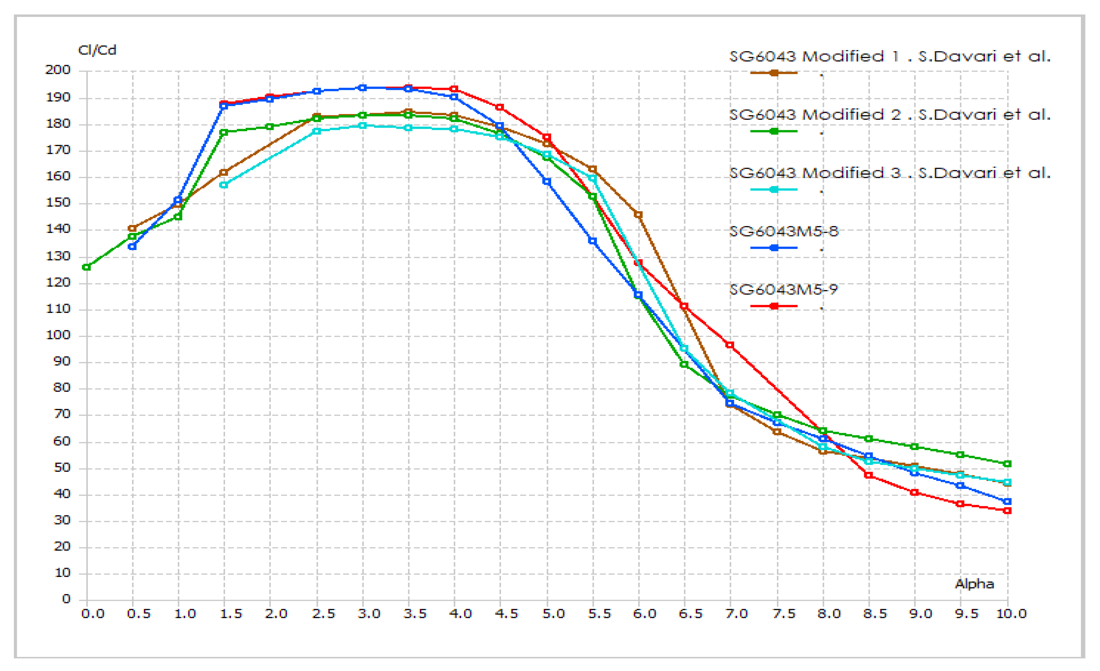
The optimised variants were compared against existing literature to quantify improvements. Figure 9 presents a direct comparison of the three optimised variants (SG6043M5-6, SG6043M5-8, and SG6043M5-9) with the EYO series developed by (Osei and et al., 2020) at . At this Reynolds number, the SG6043M5-8 achieved a ratio of 179.11, surpassing the best EYO variant (EYO7-8, ratio 169.68) by approximately 5.5%. Similarly, Figure 10 compares the optimised variants with the SG6043 Modified series from Davari and et al. (2023) at , where the SG6043M5-9 (193.44) outperformed the “SG6043 Modified 1” (184.85) by 4.6%.
These improvements are statistically significant, exceeding the calculated computational uncertainty bounds of .
Figure 9.
Comparison of modified airfoils SG6043M5-6, SG6043M5-8 and SSG6043M5-9 with EYO series (Osei et al.) at Re. 5 x 10⁵.
Figure 9.
Comparison of modified airfoils SG6043M5-6, SG6043M5-8 and SSG6043M5-9 with EYO series (Osei et al.) at Re. 5 x 10⁵.
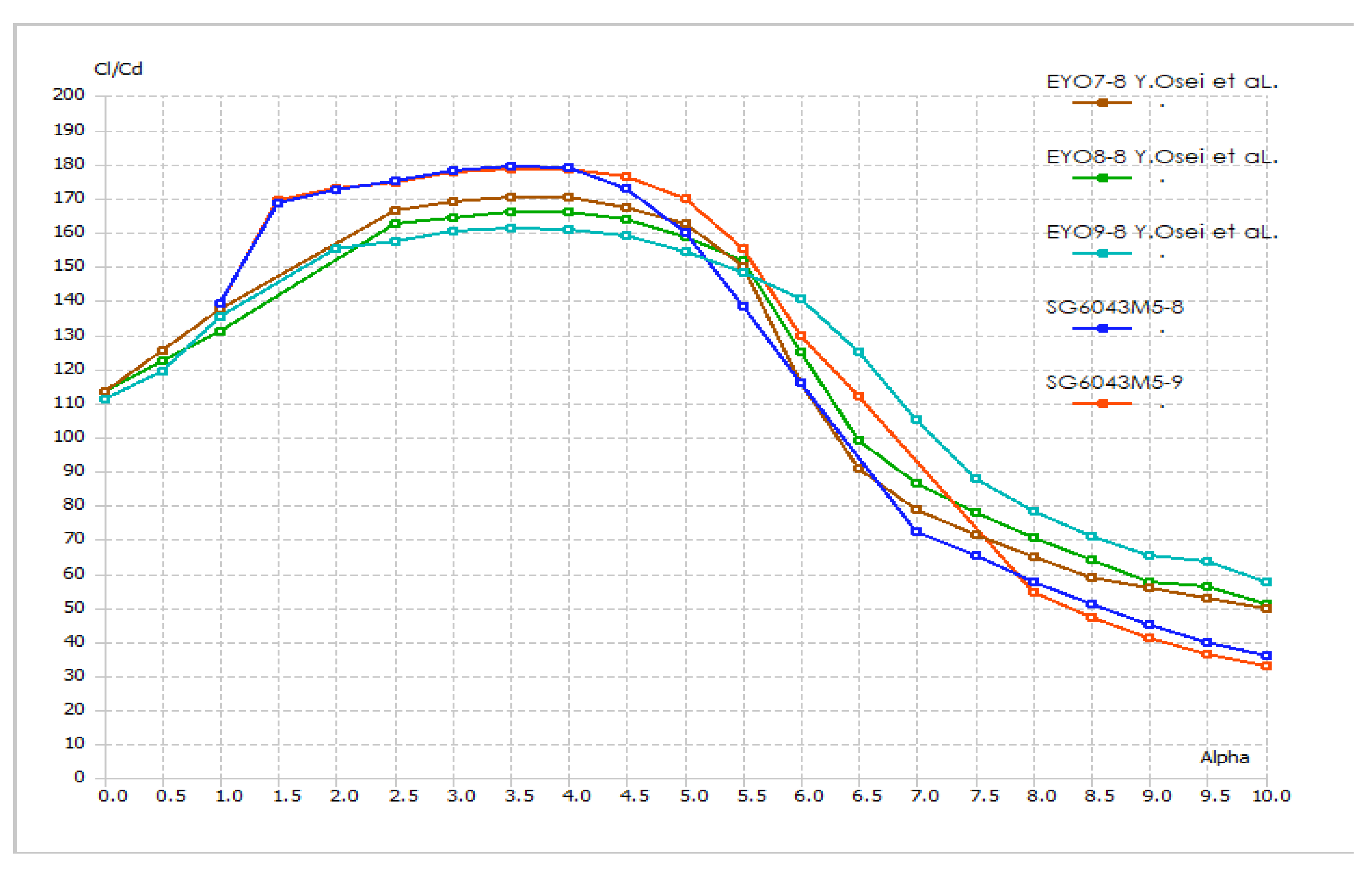
Figure 10.
Comparison of modified airfoils SG6043M5-6, SG6043M5-8 and SSG6043M5-9 with SG6043 Modified 1,2 and 3 series (Davari et al.) at Re. 6 x 10⁵.
Figure 10.
Comparison of modified airfoils SG6043M5-6, SG6043M5-8 and SSG6043M5-9 with SG6043 Modified 1,2 and 3 series (Davari et al.) at Re. 6 x 10⁵.
3.4. Stall Characteristics and Practical Implications
Stall analysis using XFOIL indicates that the M5-6 variant exhibits gradual stall characteristics (), beneficial for control stability in variable winds. The higher camber variants (M5-9) show sharper stall characteristics (), necessitating precise pitch control. Although the 5% thickness presents structural challenges, preliminary analysis suggests these can be mitigated using modern high-strength composites, though detailed 3D structural modelling remains a necessary future step.
4. Conclusions and Future Work
This study successfully optimised the SG6043 airfoil for small HAWT applications through a rigorous parametric sweep of thickness and camber distributions. The investigation yielded several key findings regarding aerodynamic performance at low Reynolds numbers ( to ). The reduction of airfoil thickness to 5% consistently yielded the highest lift-to-drag ratios due to reduced form drag, while the optimal camber was found to be dependent on the Reynolds number. Specifically, the SG6043M5-6 (6% camber) proved optimal for very low Reynolds numbers (), while the SG6043M5-9 (9% camber) achieved a peak of 193.44 at .
Quantitative comparisons demonstrate that the optimised variants significantly outperform existing designs in the literature. The SG6043M5-9 variant represents a 26.5% improvement over the baseline SG6043. Furthermore, the optimised designs demonstrated a 4.6% improvement over the recent modifications by Davari and et al. (2023) and a 5.6% improvement over the EYO series by Osei and et al. (2020). These gains are statistically significant, exceeding the computational uncertainty bounds, and highlight the effectiveness of the systematic parameter sweep methodology employed in this study.
The practical implications for small wind turbine design are substantial. The SG6043M5-8 variant emerged as the most versatile candidate, offering a balanced performance profile across mid-range Reynolds numbers (), making it highly suitable for turbines operating in variable wind speeds. However, the adoption of 5% thickness airfoils requires careful consideration of manufacturing tolerances and structural integrity. High-strength materials such as carbon fibre composites would be essential to withstand operational bending moments while maintaining the thin geometric profile required for aerodynamic efficiency.
Future work:
- For future work, it is recommended to perform a detailed Computational Fluid Dynamics (CFD) analysis of the SG6043 airfoil to achieve more accurate and reliable aerodynamic predictions.
- In the future, a 2D experimental analysis of the SG6043 airfoil in a wind tunnel is recommended, and the resulting data should be used to validate CFD simulations.
Nomenclature
Acronyms
- HAWT: Horizontal Axis Wind Turbine
- UAV: Unmanned Aerial Vehicle
- AOA: Angle of Attack
- CFD: Computational Fluid Dynamics
- BEM: Blade Element Momentum
- NREL: National Renewable Energy Laboratory
- SG6043M5-6 = SG (Selig–Giguere series) + 6043 (base airfoil) + M (modified version) + 5% Thickness + 6% Cumber.
Symbols
| Symbol | Description | Unit |
| Lift coefficient | - | |
| Drag coefficient | - | |
| Moment coefficient | - | |
| Lift-to-drag ratio | - | |
| Reynolds number | - | |
| Angle of attack | degrees | |
| Thickness-to-chord ratio | % | |
| Chord length | m | |
| Maximum thickness | m | |
| Freestream velocity | m/s | |
| Air density | kg/m³ | |
| Dynamic viscosity | Pa·s | |
| Critical amplification factor | - |
Subscripts
- max: Maximum value
- opt: Optimal value
- base: Baseline configuration
- stall: Stall condition
Funding
This research did not receive any specific grant from funding agencies in the public, commercial, or not-for-profit sectors.
Ethics, Consent to Participate, and Consent to Publish
Not applicable.
Data Availability
A Data Availability statement has been added explaining the reason for not making the data publicly available and confirming that the data can be obtained from the corresponding author upon reasonable request.
Competing Interests
The authors declare that they have no competing interests.
References
- M. Alaskari, O. Abdullah, and M. H. Majeed, “Analysis of wind turbine using QBlade software,” IOP Conference Series: Materials Science and Engineering, vol. 518, p. 032020, 2019. [CrossRef]
- A. Betz, Introduction to the Theory of Flow Machines. Oxford, UK: Pergamon Press, 1966.
- Seifi Davari, H., Chowdhury, H., Seify Davari, M., & Hosseinzadeh, H. (2024). Optimizing airfoil efficiency for offshore turbines through aerodynamic geometry enhancement. Mathematical Analysis and its Contemporary Applications, 6(1), 69-93. [CrossRef]
- M. Drela, “An analysis and design system for low Reynolds number airfoils,” in Low Reynolds Number Aerodynamics, Springer, 1989.
- P. Giguère and M. S. Selig, “Low Reynolds number airfoils for small horizontal axis wind turbines,” Wind Engineering, vol. 21, pp. 367–380, 1997.
- P. Giguère and M. S. Selig, “New airfoils for small horizontal axis wind turbines,” Journal of Solar Energy Engineering, vol. 120, pp. 108–114, 1998. [CrossRef]
- S. J. Miley, A catalog of low Reynolds number airfoil data for wind turbine applications, Report RFP-3387, UC-60, 1982.
- E. Osei et al., “Development of High Performance Airfoils for Application in Small Wind Turbine Power Generation” Renewable Energy Focus, vol. 34, pp. 1–10, 2020.
- E. Y. Osei, R. Opoku, A. K. Sennu, and M. S. Adaramola, “Development of high performance airfoils for application in small wind turbine power generation,” Journal of Energy, 2020, Art. no. 9710189. [CrossRef]
- N. Prakash, J. Noronha, and M. Krishna, “Design and analysis of micro horizontal axis wind turbine using MATLAB and QBlade,” International Journal of Advanced Science and Technology, vol. 29, pp. 8877–8885, 2020. [CrossRef]
- A. Said, M. Islam, M. A. K. M. Mohiuddin, and M. Idres, “Performance analysis of a small capacity horizontal axis wind turbine using QBlade,” International Journal of Innovative Technology and Exploring Engineering, vol. 7, 2019.
- H. Seifi Davari, M. Y. Abdollahzadeh Jamalabadi, and M. Seify Davari, “Optimizing the SG6043 airfoil for small wind turbines at low Reynolds numbers using XFOIL,” Mechanical Engineering Advances, vol. 3, p. 2486, 2025.
- M. S. Selig and B. D. McGranahan, “Wind tunnel aerodynamic tests of six airfoils for use on small wind turbines,” Journal of Solar Energy Engineering, vol. 126, pp. 986–1001, 2004. [CrossRef]
- H. Shah, N. Bhattarai, S. Mathew, and C. Lim, “Low Reynolds number airfoil for small horizontal axis wind turbine blades,” Journal of Physics: Conference Series, vol. 123, 2012.
- H. Shah, S. Mathew, and C. M. Lim, “A novel low Reynolds number airfoil design for small horizontal axis wind turbines,” Wind Engineering, vol. 38, pp. 377–391, 2014. [CrossRef]
- R. K. Singh, M. R. Ahmed, M. A. Zullah, and Y. H. Lee, “Design and testing of a low Reynolds number airfoil for small horizontal axis wind turbines,” Renewable Energy, vol. 42, pp. 66–76, 2012. [CrossRef]
- A. Suresh and S. Rajakumar, “Design of small horizontal axis wind turbine for low wind speed rural applications,” Materials Today: Proceedings, vol. 21, pp. 1–6, 2019.
- J. Wata, M. Faizal, B. Talu, L. Vanawalu, P. Sotia, and M. R. Ahmed, “Studies on a low Reynolds number airfoil for small wind turbine applications,” Science China Technological Sciences, vol. 54, pp. 1684–1688, 2011. [CrossRef]
- D. Marten, J. Wendler, G. Pechlivanoglou, C. N. Nayeri, and C. O. Paschereit, “QBlade: An open source tool for design and simulation of horizontal and vertical axis wind turbines,” International Journal of Emerging Technology and Advanced Engineering (IJETAE), vol. 3, no. 3, pp. 264–269, 2013.
Figure 6.
High lift to drag ratio modified SG60435 airfoils.
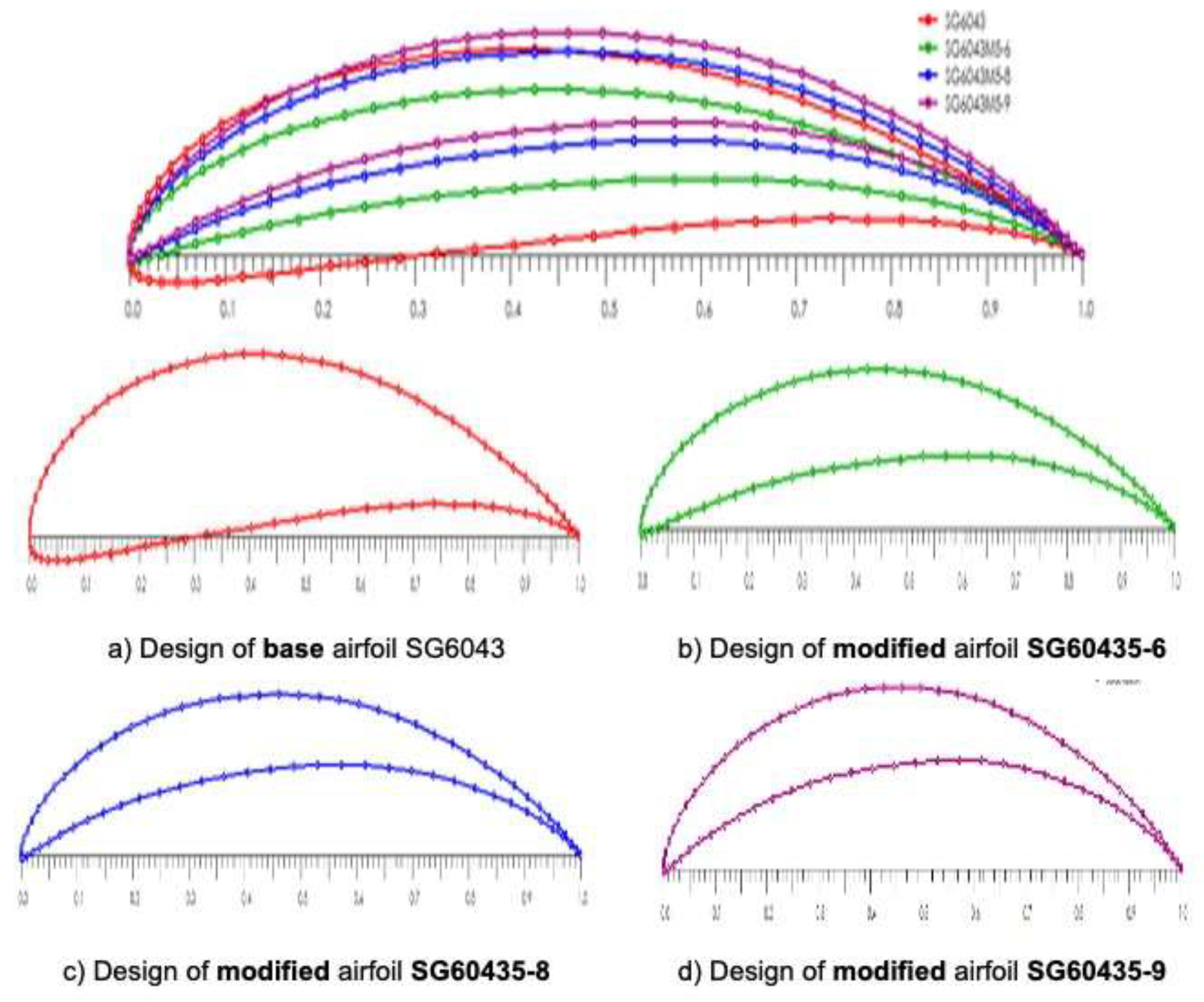

Table 1.
Summary of Key Literature on Low Reynolds Number Airfoils for Small Wind Turbines.
| Year | Authors | Reference | Method / Software | Airfoil(s) | Key Outcome | Maximum lift-to-drag ratio (CL/CD) |
| 1998 | Giguère & Selig | (Giguère and Selig, 1998) | Experimental – Wind Tunnel | SG6040-43 | SG6043 identified as superior | 125 |
| 2004 | Selig & McGranahan | (Selig and McGranahan, 2004) | Experimental – Wind Tunnel | Multiple | Comparative airfoil tests | - |
| 2011 | Singh et al. | (Singh et al., 2012) | Experimental – Wind Tunnel | Novel | Low Re design for HAWT | - |
| 2019 | Alaskari et al. | (Osei et al., 2020) | Computational – Custom CFD | SG6043 | - | |
| 2020 | Osei et al. | (Osei and et al., 2020) | Computational – QBlade | EYO Series | Three modified SG6043 variants | 170 |
| 2023 | Davari et al. | (Davari and et al., 2023) | Computational – XFOIL | SG6043-Mod | Thickness-to-camber optimisation | 184.85 |
| 2023 | Alsahlani et al. | (Said et al., 2019) | Computational – XFOIL | NACA/SG | Geometry impact study | - |
Table 2.
Validation of reported XFOIL performance of SG6043 with QBlade.
| Re. No | AOA | CL/CD (XFOIL Ref) | CL/CD (Current QBlade) | Data Source |
| 1 × 10⁵ | 7° | 66.5 | 66.0 | (Giguère and Selig, 1998) (Comp) |
| 2 × 10⁵ | 5.5° | 98.0 | 98.0 | (Giguère and Selig, 1998) (Comp) |
| 3 × 10⁵ | 4° | 117.0 | 117.0 | (Giguère and Selig, 1998) (Comp) |
| 4 × 10⁵ | 4° | 132.5 | 132.5 | (Giguère and Selig, 1998) (Comp) |
| 5 × 10⁵ | 3.5° | 143.0 | 144.0 | (Giguère and Selig, 1998) (Comp) |
| 6 × 10⁵ | 3° | 152.8 | 152.8 | (Giguère and Selig, 1998) (Comp) |
Table 3.
Maximum lift-to-drag ratio () for optimised airfoil variants.
| Airfoil Variant | Thickness (%) | Camber (%) | Reynolds Number | Optimal AOA (∘) | Max CL/CD |
| SG6043M5-6 | 5 | 6 | 1 × 10⁵ | 6.0 | 76.48 |
| SG6043M5-6 | 5 | 6 | 2 × 10⁵ | 5.0 | 112.31 |
| SG6043M5-8 | 5 | 8 | 3 × 10⁵ | 4.5 | 140.55 |
| SG6043M5-8 | 5 | 8 | 4 × 10⁵ | 4.0 | 161.86 |
| SG6043M5-8 | 5 | 8 | 5 × 10⁵ | 3.5 | 179.11 |
| SG6043M5-9 | 5 | 9 | 6 × 10⁵ | 3.5 | 193.44 |
Disclaimer/Publisher’s Note: The statements, opinions and data contained in all publications are solely those of the individual author(s) and contributor(s) and not of MDPI and/or the editor(s). MDPI and/or the editor(s) disclaim responsibility for any injury to people or property resulting from any ideas, methods, instructions or products referred to in the content. |
© 2026 by the authors. Licensee MDPI, Basel, Switzerland. This article is an open access article distributed under the terms and conditions of the Creative Commons Attribution (CC BY) license (http://creativecommons.org/licenses/by/4.0/).
Copyright: This open access article is published under a Creative Commons CC BY 4.0 license, which permit the free download, distribution, and reuse, provided that the author and preprint are cited in any reuse.