Submitted:
09 February 2026
Posted:
11 February 2026
You are already at the latest version
Abstract
This paper investigates the feasibility of interior permanent magnet (IPM) rotor for a 1MW-class high-speed permanent magnet synchronous machines (PMSMs) in hybrid propulsion system of electrified aviation. A double-layer IPM machine and a surface-mounted PM (SPM) benchmark machine with Halbach-array PMs, which are typical employed in the aviation applications, are designed using the same design specifications, the same stator, double-three-phase winding layout, physical air-gap length, outer and inner diameters of rotor, and the same materials. The rotor robustness of IPM machine using high-strength iron material has been verified through mechanical strength analysis with outstanding safety factor margin. The electromagnetic performances of IPM and SPM benchmark machines are compared. It is found that the IPM design can achieve similar high torque/power density and high efficiency to the SPM benchmark machine, using 48% less rare-earth PM materials and simpler rotor structure without carbon-fiber sleeve for easy manufacturing. The investigation confirms the feasibility of IPM topology for MW-class high speed aviation propulsion machines for lower cost and more sustainable purposes.
Keywords:
interior permanent magnet rotor
; permanent magnet synchronous machine
; high-speed machine
; hybrid propulsion
1. Introduction
The global aviation sector is currently navigating a profound technological transformation from fully fossil-fuel power towards electrification, which is a movement primarily spurred by the urgent demands to mitigate the environmental impact and emission of air travel, and to enhance operational efficiency [1,2]. The critical shift towards cleaner and more sustainable propulsion technologies in the aviation industry as a significant contributor to global carbon dioxide and nitrogen oxides emissions while exposing damages to the ozone layer calls for innovation and advancement in fully or partially electrification through the integration of on-board power electronics, electrical machine and power distribution systems [3,4]. In literatures, different concepts and architectures of electrical propulsions systems have been proposed, including all-electric aircrafts (AEA) with full power from energy storage in the form of electricity, and more electrical aircrafts (MEA) that utilize the concepts of hybrid electrical or turbo-electrical power propulsions to enhance the efficiency of fuel-based turbine system with reduced emissions [1,5,6]. Although AEA is more promising for the ambitious goal of net Zero aviation industry, the current capability of electrical energy storage density in battery packs limits the applications of AEA concept to commercial flights using single-aisle or double-aisle airliners. Thus, MEA concept with hybrid electrical propulsion have gained increasing attentions as the solution for electrical propulsion [7], with main concepts including parallel hybrid electrical propulsion, all turboelectric propulsion, series hybrid electrical propulsion, partially turboelectric propulsion, and series/parallel partial hybrid electric propulsion. A typical schematic concept of hybrid electrical propulsion system is briefly shown in Figure 1.
The transition to hybrid electric propulsion fundamentally alters the aircraft’s power system architecture, replacing traditional hydraulic and pneumatic power sources with electrical counterparts [8]. This shift results in a dramatic increase in onboard electrical power demand, moving from hundreds of kilowatts in conventional aircrafts to the multi-megawatt (MW) scale required for propulsion and high-power generation in regional and single-aisle aircraft [9]. Future projections indicate that the power capacity on aircraft could exceed ten MW [10]. To meet this unprecedented demand, the core challenge lies in developing electrical machines that possess an extremely high specific power density, high efficiency, mechanical strength, and exceptional reliability, all while operating under the severe constraints of the aerospace environment, including high altitude, low pressure, and wide temperature variations [11]. As a result, the design of electrical machines must consider multi-physics characteristics at multiple domains including electromagnetic, mechanical, and thermal performance.
Although different types of electrical machines have been considered for aerospace applications including would-field synchronous machines (WFSMs), induction machines (IMs), and switched reluctance machines (SRMs) [12], permanent magnet (PM) synchronous machines have emerged as the leading candidate thanks to the superior torque/power density, light weight, high efficiency, and fault-tolerant capability [13], as the main competitors shows major drawbacks on lower efficiency and reliability concerns (WFSM), lower power density and power factor (IM), and higher noises and vibrations (SRM).
There are various topologies of PM machines that have been considered and investigated for aviation applications. Axial-flux PM (AFPM) machines, which offer advantages in terms of compactness and potentially high torque density, have been investigated for 3-5k r/min speed and 100-700kW applications [14,15]. The industrial demonstrations confirms that the yokeless AFPM concepts can increase power density by reducing the iron mass and shortening the end windings. However, the geometrical characteristics of existing AFPM machines with short axial length and large rotor diameter restrict the specifications of high speed and high electrical loading due to concerns on mechanical and thermal reliability [16], limiting the applications towards MW-class high-speed propulsion cases. Slotless stator concept with air-gap windings can reduce core losses and mitigate torque ripple and cogging torque, which has been employed for a 2.5MW aviation generator design in [17] and shows 99% efficiency. Double-rotor and double-stator topologies have been explored in [18] through comparing with conventional single rotor concepts using both outer and inner rotor designs. It is found that the double-rotor design shows superior power density reaching 34kW/kg at 18000 r/min, around 50% higher than the second highest single inner rotor design. Nevertheless, double-rotor concept is mechanically complicated particularly in the manufacturing perspective, and the structure will also significantly limit the cooling capability of the stator, which restricted the practical application of double-rotor approaches.
In literature, single rotor PM machine with surface-mounted PMs (SPMs) and slotted stator remains to be the dominant selection for MW-class high speed PM machines for electrical aviation application, which are briefly summarized in Table 1. In general, most of the cases use inner rotor topologies and Litz wire windings to reduce AC copper loss, while the out-rotor concept is investigated as a potential approach to integrate the machine into ducted turbo-fan for a compact solution [19]. An attempt of utilizing hairpin windings in the stator armature is reported in [22], which aims to rebalance the DC and AC copper losses while reducing the overall volume and weight. In general, it is found, particularly by results from experimental demonstrations in [19,23], that MW-class PM machines can reach >11 Nm/kg high torque density and >97% high efficiency at the rated full power condition.
All existing designs shown in Table 1 utilize Halbach-array thanks to the superior characteristics on air-gap side enhanced magnetic field to reduce rotor yoke thickness and sinusoidal magnetic field distribution, thereby improving power density by further reducing the weight of rotor iron core and improving efficiency through less magnetic harmonic distortion, respectively. However, the drawbacks of Halbach-array based PM arrangement design include significant rare-earth PM usage with high cost and complexity on manufacturing, particularly on PM magnetization, bonding of many PM segments, and sleeve assembly [9,16,19,23].
Interior PM (IPM) machines with PMs embedded inside the rotor iron core have been widely used in electrical vehicle industries [24,25], which benefits from simple and easy manufactured rotor structure, and less expensive rare-earth PM usage to ease supply-chain concerns and enable more cost-effective solution, compared with SPM designs. However, one of the most critical concerns for employing IPM topology in high power density and high-speed PM machines in aviation applications is the mechanical strength, as regular silicon steel material with 0.2-0.5 mm thickness usually has a yield strength at around 300-400MPa, which usually fail to ensure reasonable safety margin for the reliability and rotor robustness for aviation applications. The development and commercialization of high strength silicon steel, which shows the increase of yield strength to around 1000MPa [26], originally targeted the EV sector, opens a new opportunity for applicable IPM solution in the electrical aviation sector.
As all existing papers only focus on SPM rotor topologies for MW class high speed PM synchronous machines for electrical aviation propulsion applications, this paper aims to fill the gap by exploring the feasibility of a 1MW, 12k r/min IPM machine for hybrid electrical propulsion system in electrical aircraft, using as a generator. The advantages and disadvantages of IPM rotor-based MW class high speed PM machines are revealed by comparing with a SPM machine using Halbach-array PMs, with the same specifications, stator design, physical air-gap length, and rotor inner diameter. It is firstly validated that an IPM machine can achieve similar power density for active material weight and similar efficiency considering mechanical robustness, with much lower rare-earth PM material usage, lower cost, and easier manufacturing process.
This paper is organized as follows. In Section II, the specification of 1MW generator for hybrid aviation propulsion and the selections of topologies and designs of both IPM machine and the SPM benchmark machine using Halbach-array PM configuration are given. Section III present the mechanical stress analysis of IPM machine design to validate the mechanical robustness of the IPM rotor. The electromagnetic performance of IPM and SPM machines are compared in Section IV. Finally, a conclusion is given in Section V.
2. Machine Specification and Designs
In this paper, an IPM machine and a SPM benchmark machines using Halbach-array PMs are designed using the same specifications for a 1 MW-class, high-speed generator in hybrid electrical propulsion system of MEA. To enable a fair comparison, both IPM and SPM machines are designed using the same stator, armature winding layout, physical airgap-length, and rotor inner diameter to ensure the same volume of machine. To improve power density, reduce armature harmonics related losses, and enable fault-tolerant capability, dual-three-phase (DTP) stator winding layout will be employed, similar as other reported 1 MW-class aviation generator demonstrators [19,22]. For the SPM machine, a retaining sleeve made of non-conductive and non-permeable carbon fiber sleeve is employed to provide pre-tightening force for Halbach-array PMs with PM segments, securing the mechanical strengths of SPM rotor at high-speed conditions. Although thinner sleeves can also be used in IPM machines for mechanical robustness enhancement, such as the application in Tesla EV motor, it has not been employed in the IPM rotor design in this work, which means the IPM machine only use rotor iron core with embedded PMs.
In this section, the generator specifications that are applied to both IPM and SPM benchmark machines and the same stator design shared by SPM and IPM machines are given firstly. Then, the rotor designs of both SPM benchmark machine using Halbach-array PMs and IPM machine are presented using the same physical air-gap length and rotor inner diameter.
2.1. Specifications of 1 MW-Class High-Speed Generator and Stator Design
As reviewed in Section 1, the primary goals for electrical machine design in the aviation industry focus on enhancing the power density as the ratio between rated power and weight of active materials and efficiency. The specifications of a 1 MW-class high-speed generator for hybrid electrical propulsion system in MEA are given in Table 2, which shows similar characteristics on size, rated power, efficiency, speed, DC link voltage, and current density as other demonstrations reported in literature [17,19,23]. The criteria of mechanical rotor safety factor is defined as the ratio between maximum stress at the rated condition and the yield/tensile strengths of rotor materials, as given in (1), where σmax is maximum Von-Mises stress (for iron core) or Maximum Principal stress (for PMs), and σy is the yield strength for iron materials or tensile strength for PMs.
The stator is designed based on the specifications and requirements of high-speed aviation propulsion generator, and the main stator design parameters are listed in Table 2. High permeability Fe-Co-V alloy material with higher saturated magnetic flux density compared with conventional electrical silicon steel core material is employed for the stator core to improve the power density of machine, which is usually used for machine in the aviation sector that requiring superior power density. Litz bundles are used for stator coils to minimize AC winding considering the high frequency currents flow through the windings and high frequency magnetic fields, including fundamental and harmonic components, that interact with the conductive coils, which may generate significant AC copper loss due to the skin effect and proximity effect in high-speed machines using form-would copper wires or hair-pin coils. The geometry of stator core and winding layout in one pole is shown in Figure 2 (a), and the phase EMF phasor diagram is illustrated in Figure 2 (b). The same stator design will be shard by both IPM and SPM benchmark machines to indicate a fair comparison. The drive circuit of the DTP PM machine is illustrated in Figure 3, as the two sets of three phase windings are controlled individually by two three-phase inverters to offer redundancy and fault-tolerant capability. The power electronic DC/AC inverter using verified Si IGBT based power module is employed with 20kHz switching frequency to consider the influences of harmonic currents on the machine performance [27].

Table 3.
Main design parameters of stator.
| Parameters | Values |
| Slot number | 96 |
| Pole number | 16 |
| Stator outer diameter | 300 mm |
| Stator inner diameter | 246 mm |
| Slot type | In-parallel slot |
| Slot width | 4 mm |
| Slot depth | 19 mm |
| Conductor number per slot | 2 |
| Coil pitch | Full-pitch |
| Parallel branches per phase | 8 |
| Winding connection | Delta |
| Stator stack length | 190 mm |
| Stator length including end-windings | 250 mm |
| Stator core material | Fe-Co-V alloy |
| Stator core plate thickness | 0.1 mm |
| Stator winding material | Cu |
| Stator winding wire type | Litz wire |
| Maximum current density | 20 A/mm2 |
| PWM switching frequency | 20 kHz |
2.2. Rotor Designs of IPM and SPM Benchmark Machines
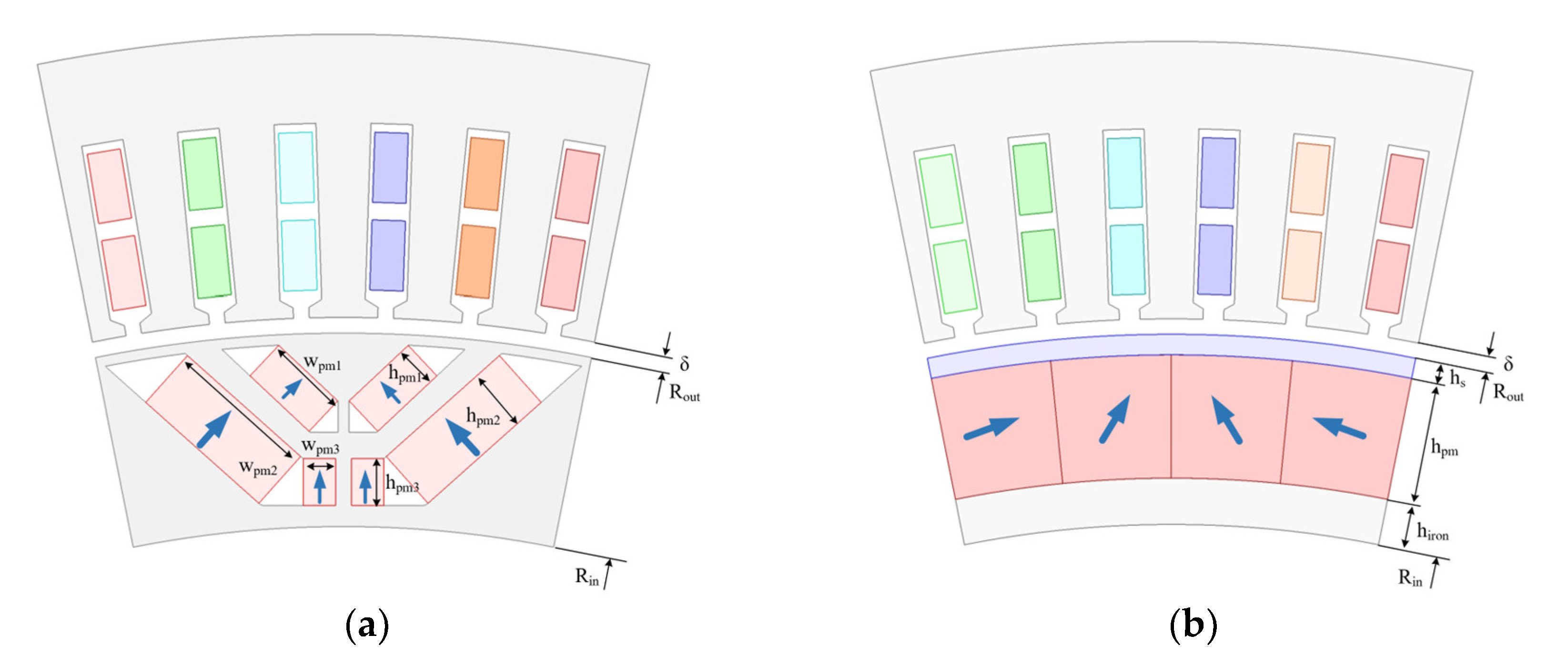
The SPM benchmark rotor and IPM rotor are designed and optimized using the same outer and inner diameters, PM material and iron core material. The SmCo PMs are employed as a regular selection in aviation sector due to outstanding thermal stability. Due to the same stator inner diameter and the same rotor outer diameter, the physical airgap of both IPM and IPM machines remains the same. The geometries of optimized IPM and SPM benchmark machines are illustrated in Figure 4, where blue arrows are used to denote the magnetization directions of PMs. Main design parameters of both machines, including geometrical parameters denoted in Figure 4, are listed in Table 4.
The IPM rotor is designed using the same air-gap length δ, and outer and inner diameters of rotor, Rout and Rin, respectively. Thus, the IPM rotor has the same volume as the SPM rotor including the sleeve. As can be seen in Figure 4, a double-layer V+ U shape IPM topology is selected to better utilize both PM and reluctance torques after comparison between regular IPM topologies, in order to improve the torque density and reduce the harmonics of rotor magnetic field and back EMFs. The iron bridges and ribs are design to ensure the mechanical strength with outstanding safety margin as required in Table 2. As shown in Table 4, the PM usage in the SPM benchmark machine is significantly larger than the IPM machine, with a 94.3% more PM volume, which demonstrates the merit of IPM machine on reducing rare-earth PM usage.
The rotor design of SPM machine employs Halbach array employs 4 segments of PMs per pole [17] with sinusoidal magnetization to ensure a sinusoidal magnetic field with high torque density and low torque ripple, while also considering a compromise between performance and manufacturability. A carbon fiber is employed to protect the PMs and secure the mechanical strength of rotor as many components of PMs are attached at the surface of a thin rotor back iron, which is also an advantage of Halbach-array PMs by enhancing the magnetic field in the air-gap side while suppressing it in the rotor yoke side to reduce the thickness and yoke of rotor iron. To mitigate the torque ripples and harmonics, an axially V-shape 5 segment stepping design is also included in the IPM rotor.
3. Mechanical Strength Analysis for IPM Machine Design
One of the main concerns for the feasibility of utilizing IPM topologies in MW-class high-speed PM machines in the electrified aviation sector remains to be the mechanical robustness and notable safety margin criteria, as the mechanical strengths of SPM machine design with Halbach-array and carbon fiber sleeve with similar size, speed, and design parameters has been validated in literature and reported demonstrations in Table 1. In this section, mechanical finite element (FE) analysis is carried out to calculate the von-Mises stress distribution on rotor iron core and the maximum principal stress on the PMs. Through comparison with yield stress for iron core material and tensile stress for PM materials, respectively, the mechanical safety factors across a speed range, particularly on the rated speed, can be obtained for iron core and PMs, to validate the mechanical strengths of the IPM design. The mechanical characteristics of iron core and PM materials used in the FE simulation are shown in Table 5
Table 5.
Main design parameters of IPM and SPM rotors.
| Item | 35SWY900 | SmCo Recoma 35E |
| Density (kg/mm3) | 7600 | 8300 |
| Young’s modulus (GPa) | 180 | 140 |
| Poisson ratio (-) | 0.3 | 0.34 |
| Tensile strength (Mpa) | - | 35 |
| Yield strength (Mpa) | 960 | - |
The distributions of von-Mises stress on the rotor iron core at different rotation speed and constant rated 835 Nm torque are shown in Figure 4. As can be seen, maximum von-Mises stress remains to be located on the bottom of the second layer rib across a range of speed, reflecting the influences of both centrifugal force and torque, which is also gradually increase with the increase of rotational speed. The maximum von-Mises stress on the rated speed and torque, namely 12000 r/min and 835 Nm, is around 383.2 Mpa, which is significantly lower than the 960 Mpa yield strength of used rotor iron steel material, demonstrating the mechanical robustness of IPM design at the rated condition. The distributions of maximum principal stress on the PMs at different rotation speed and constant rated 835 Nm torque are shown in Figure 5. As illustrated in Figure 5 (a), the maximum principal stress on the PMs reaches around 16.66 Mpa, that is smaller than half of the tensile strength of PMs, also demonstrating the mechanical strengths of PMs at the investigated conditions.
To better understand the safety margin of mechanical strengths in the IPM designs across a speed range for both iron core and PMs, the safety factors of rotor core and PMs are calculated for different speed conditions based on equation (1), as shown in Table 5. It confirms that the mechanical safety factor at the rated condition meet the criteria of SF>2 given in Table 1, which validate the mechanical robustness of the proposed IPM design. Moreover, the comparison also indicated that the maximum speed of this IPM design should not exceed 16500 r/min, considering a minimum >1.1 safety factor as a boundary condition. As the maximum stress on the iron core reaches the criteria at close to 13500 r/min, it may be possible to further increase the rated speed of this design for the purpose of power density enhancement with the same output torque, subject to the careful improvement on PMs geometric and assembly designs to ensure an acceptable SF on PMs.
Figure 6.
Maximum Principal stress distributions on PMs at different rotation speed and constant rated 835 Nm torque. (a) 12000 r/min. (b) 15000 r/min. (c) 18000 r/min.
Figure 6.
Maximum Principal stress distributions on PMs at different rotation speed and constant rated 835 Nm torque. (a) 12000 r/min. (b) 15000 r/min. (c) 18000 r/min.
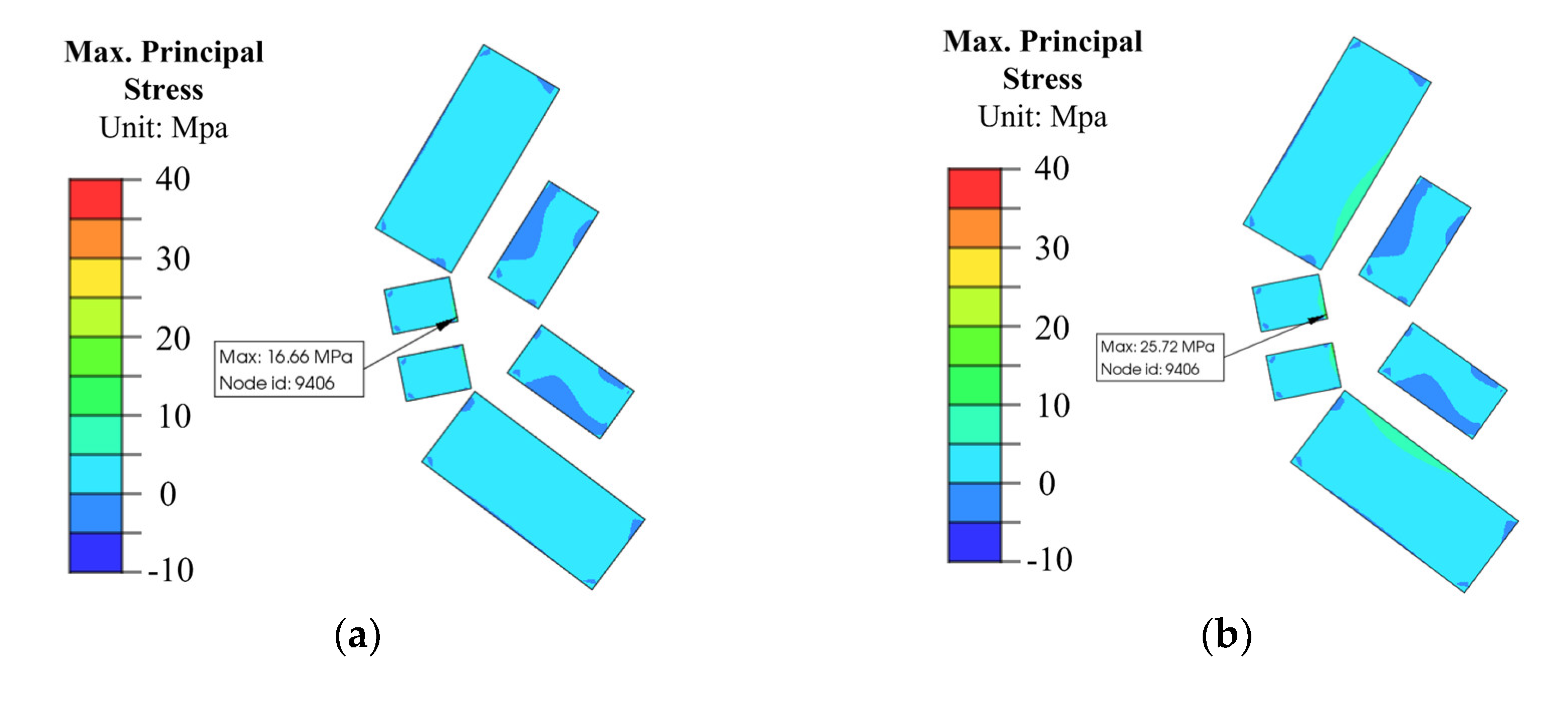
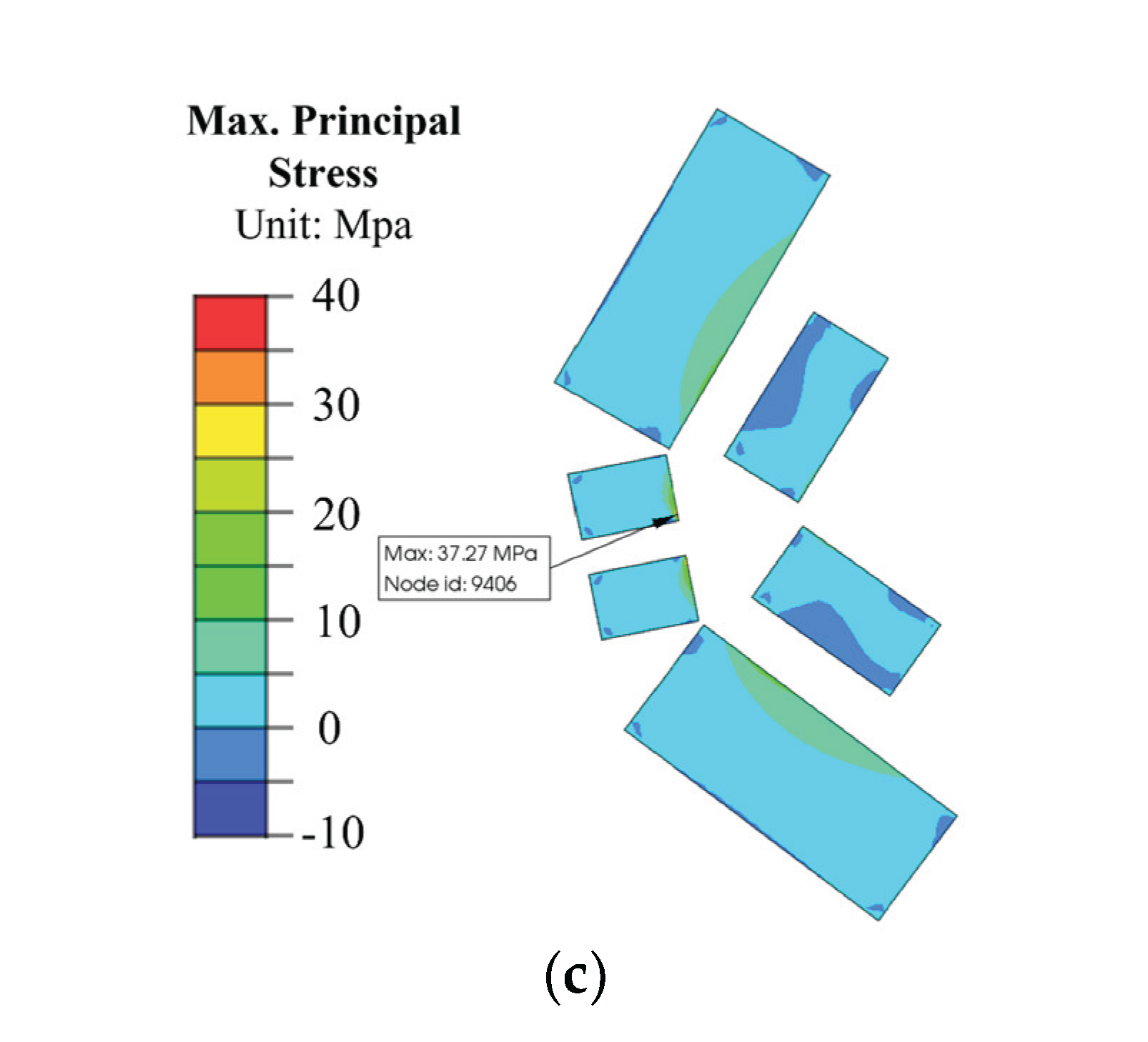
Table 5.
Safety margin of mechanical strength for IPM machine across a speed range.
| Speed (r/min) | Rotor Iron Core | PMs | ||
| Max. Von-Mises stress (MPa) |
SF (-) |
Max. Principal stress (MPa) |
SF (-) |
|
| 12000 | 383.2 | 2.51 | 16.66 | 2.10 |
| 13500 | 481.5 | 1.99 | 21.15 | 1.65 |
| 15000 | 557.3 | 1.72 | 25.72 | 1.36 |
| 16500 | 698.9 | 1.37 | 31.51 | 1.11 |
| 18000 | 852.3 | 1.13 | 37.27 | 0.94 |
4. Comparison of Electromagnetic Performance Between IPM and SPM Benchmark Machines
While the analysis in Section 3 confirms the mechanical strengths and feasibility of IPM machine design for the design specifications and criteria of hybrid aviation propulsion generator, this section will focus on the comparison on electromagnetic performance between IPM and SPM machines to understand the merits and demerits of IPM machines compared with the SPM benchmark machine whose topology has already been widely employed in the electrical aviation industry.
4.1. Open-Circuit Performance
The distributions of magnetic flux density and flux lines at open-circuit condition in IPM and SPM benchmark machines are illustrated in Figure 7. As can be seen, the SPM benchmark machine has higher magnetic flux density in the stator side, due to more PM usage, the superior magnetic enhancement effect of Halbach-array, notable leakage fluxes in the rotor bridges and ribs of IPM machine, while the magnetic flux density in the SPM machine has also reduced due to the influences of non-permeable carbon fiber sleeve with 2mm thickness, which actually increase the equivalent air-gap length of SPM machine to 3.5 mm, compared with the 1.5 mm equivalent air-gap length in IPM machine that remains to be the same as physical air-gap length.
Consequently, the SPM benchmark machine shows about 15% higher fundamental flux density as shown in Figure 8 (a) and 15% higher fundamental back electromotive force (EMF) as shown in Figure 9 (a), which matches the observed magnetic flux density distributions in Figure 7 and aligns with the better magnetic focusing effect of Halbach-array PMs and more PM usage. However, in the perspective of magnetic flux density and back-EMF per PM volume, the IPM machine shows much better performance than the SPM benchmark machine, as the IPM machine shows 60% higher open-circuit magnetic flux density per used PM volume, which demonstrates outstanding PM usage ratio for the IPM machine.
Besides, the SPM benchmark machine also shows significantly lower harmonic distortions, as evidenced by more than 50% and 59% lower total harmonic distortions (THDs) for magnetic flux density and back EMFs, respectively, compared with that of the IPM machine. It also reflects the outstanding harmonic elimination effect of Halbach-array PMs, even though the rotor stepping design with harmonic suppression effect has already been employed in IPM machine.
Due to the nature of IPM and SPM topologies while further influenced by the longer equivalent air-gap length in the SPM design, the IPM machine shows higher d- and q-axis inductances, compared with that of the SPM machine. Besides, the IPM machine shows a saliency ratio with 1.75, as reluctance torque can be utilized to enhance the torque/power density.
Table 6.
Comparison of open-circuit inductances between IPM and SPM machines.
| Inductance | IPM | SPM |
| d-axis inductance (mH) | 0.12 | 0.08 |
| q-axis inductance (mH) | 0.21 | 0.08 |
| Saliency ration Lq/Ld (-) | 1.75 | 1.0 |
4.2. On-Load Performance, Power Density, and Efficiency at Rated Condition
The on-load performance of both IPM and SPM benchmark machines are analyzed at rated 12000 r/min speed, 1.05MW output power conditions, and compared to verify the feasibility of employing IPM machine concept for 1MW-class high speed propulsion generator application in hybrid aviation propulsion system, with particular focus on power density and efficiency.
The torque current angle characteristics of IPM and SPM machines are shown in Figure 10. As can be seen, the maximum torque of SPM benchmark machine is obtained when current advancing angle is 0, namely d-axis current id=0, due to ignorable reluctance torque. Thus, the id=0 control can be applied for maximum torque/power density. For IPM machine, the maximum torque is achieved at a larger current advancing angle, due to utilization of both PM torque and reluctance torque components to enhance torque/power density without more PM usage. As extracted in Figure 11 using frozen permeability method [29], both PM and reluctance torque components contribute to the maximum torque, with about 12% and 88% average torque from reluctance torque and PM torque components, respectively.
The on-load torque waveforms of SPM and IPM machines at the rated condition are shown in Figure 12 (a), while their spectrums compared in Figure 12 (b). As can be seen, both machines have low torque ripples (<5%), as the percentage ratio between peak-to-peak value of torque waveform and the average torque, thanks to rotor stepping design in IPM machine albeit to a compromise of average torque, and Halbach-array PMs in SPM benchmark machine, respectively. The main order of torque harmonics in both IPM and SPM machines is 13th, which is originated from tooth-harmonics due to slot opening. Besides, the IPM machine shows 60% further lower torque ripple compared with that of the SPM benchmark machine.
The torque-speed performance of IPM and SPM machines at the same 1kV DC bus voltage and maximum 20A/mm2 current density are illustrated in Figure 13. It reveals that the IPM machines show wider speed range and higher output torque/power within the overspeed range beyond the rated speed (normally within 20-30% for safety consideration), due to better flux-weakening capability of IPM topology.
The most important performance particularly cared by the aviation industry for electrical machines in the hybrid propulsion system are power density and efficiency. To evaluate the power density as the ratio between output power and total active weight, the weights of active components and the total weights as the sum of all components are given in Table 7. As can be seen, the IPM and SPM machines generally have similar total weights. Besides, the IPM shows a significant less PM usage than the SPM benchmark machine, as the rotor PM weight in IPM is 48.6% lighter than that of SPM machine.
Based on the active weight obtained in Table 7, the on-load performance of IPM and SPM machines at rated condition, with particular emphasis on power density and efficiency, are compared in Table 8. As can be seen, the current density of IPM machine to achieve the rated power is slightly higher than that of the SPM benchmark machine, while the current harmonic ripple in the IPM is smaller than that of the SPM due to larger inductances.
As shown in Table 8, the IPM machine can achieve similar active power density and active torque density to the SPM benchmark machine, both reaching >20 kW/kg and >16 Nm/kg, respectively, which demonstrates superior performance of both IPM and SPM benchmark machine designs in this work, as evidenced by comparable power density with the state-of-the-art demonstrations listed in Table 1. The electromagnetic losses and efficiency are also shown in Table 8, as can be seen, the IPM machine has slightly higher copper loss due to slightly larger current density applied to achieve the same output torque, and higher iron losses due to higher harmonics distortion in the magnetic flux density, compared with the SPM benchmark machine. However, the IPM machine also shows much lower magnetic losses than SPM machine, as the PMs in IPM are embedded inside PM cavities in the rotor rather than directly exposed to all magnetic harmonics in the air-gap in the SPM benchmark machine. Consequently, the IPM machine has 5.7% slightly higher total losses than the SPM machine, which results in a 0.11% lower efficiency in IPM machine. As both IPM and SPM machines reach a significantly high efficiency around 98%, the difference of efficiency is minor.
Nevertheless, the comparison also reveals that IPM machine can achieve similar high-power density and superior efficiency to the SPM machine using Halbach-array PMs with notable mechanical strengths. Thus, it is demonstrated that IPM machine is feasible for 1MW-class high speed propulsion machine in the electrical aviation sector. It is also confirmed that the IPM machine design shows notable merits including significantly less rare-earth PM usage, which improves sustainability, and less complicated manufacturing requirements for the rotor. These merits will also introduce advantage on lower costs.
5. Conclusions
In this paper, a double-layer IPM machine using high-strength iron material for rotor core and a SPM machine using Halbach-array PMs have been designed, analyzed, and compared for the 1MW-class high speed generator in hybrid aviation propulsion. Through electromagnetic and mechanical analyses, it is revealed that the IPM machine meets the high criteria of safety factor at rated high-speed operation condition, and shows similar >20kW/kg high-power density and 98% high efficiency to the SPM benchmark machine, meeting the specification requirements of power density and efficiency, while using only 51.4% of total rare-earth PM usage and simplified rotor fabrication process compared with the SPM machine.
Therefore, the feasibility of using IPM topology for MW-class high-speed aviation propulsion applications has been confirmed, with highlighted less rare-earth material volume, easier manufacturing, and consequently less costs, than the conventional designs based on SPM topology using carbon fiber sleeve and Halbach-array PMs. The conclusion of this paper indicates a new technical approach for large capacity electrical machine designs in electrical aviation industry using IPM machine to achieve low cost and sustainability.
Author Contributions
Conceptualization, Y.X. and R.W.; methodology, Y.X.; software, A.Y. and Y.Z.; validation, Y.X., X.L.; formal analysis, Y.X.; investigation, Y.X.; resources, Y.X., J.Z., and R.W.; data curation, Y.X., J. Z., and R.W.; writing—original draft preparation, Y.X.; writing—review and editing, Y.X. an R.W.; visualization, Y.X.; supervision, Y.X. and R.W.; project administration, Y.X. and R.W.; funding acquisition, Y.X. and R.W., All authors have read and agreed to the published version of the manuscript.
Funding
This research was funded by University of Leicester Starting Grant, grant number P12DF143, and Royal Society Research Grant, grant number RG\R1\251624.
Data Availability Statement
The original contributions presented in the study are included in the article, further inquiries can be directed to the corresponding author.
Conflicts of Interest
The authors declare no conflicts of interest.
References
- E. Sayed et al., “Review of Electric Machines in More-/Hybrid-/Turbo-Electric Aircraft,” in IEEE Transactions on Transportation Electrification, vol. 7, no. 4, pp. 2976-3005, Dec. 2021.
- B. Sarlioglu and C. T. Morris, “More Electric Aircraft: Review, Challenges, and Opportunities for Commercial Transport Aircraft,” in IEEE Transactions on Transportation Electrification, vol. 1, no. 1, pp. 54-64, June 2015.
- C. Liao, N. Bianchi, and Z. Zhang, “Recent Developments and Trends in High-Performance PMSM for Aeronautical Applications,” Energies, vol. 17, no. 23, p. 6199, 2024.
- W. Chen, Y. Yan, Y. Qi, M. Huang, and W. Li, “Recent Development of Aircraft Electric Propulsion System: A Technical Review,” CES Transactions on Electrical Machines and Systems, vol. 9, no. 1, pp. 115-120, 2025.
- C. Gu et al., “A Multiport Power Conversion System for the More Electric Aircraft,” IEEE Trans. Transport. Electrific., vol. 6, no. 4, pp. 1707-1720, Dec. 2020.
- A. Barzkar and M. Ghassemi, “Components of Electrical Power Systems in More and All-Electric Aircraft: A Review,” IEEE Trans. Transport. Electrific., vol. 8, no. 4, pp. 4037-4053, Dec. 2022.
- Felder, J.L. NASA Electric Propulsion System Studies. 2015. Available online: https://ntrs.nasa.gov/citations/20160009274, accessed: 2026-01.
- D. Golovanovet al., “4-MW Class High-Power-Density Generator for Future Hybrid-Electric Aircraft,” IEEE Transactions on Transportation Electrification, vol. 7, no. 4, pp. 2952-2963, 2021.
- C. Dong, Y. Qian, Y. Zhang, and W. Zhuge, “A Review of Thermal Designs for Improving Power Density in Electrical Machines,” IEEE Transactions on Transportation Electrification, vol. 6, no. 4, pp. 1386-1398, 2020.
- E. K. Mikkelsen, A. Matveev, and J. K. Nøland, “High-Speed MW-Class Generator With Multi-Lane Slotless Winding for Hybrid-Electric Aircraft,”IEEE Access, vol. 11, pp. 84759-84771, 2023.
- P. Arumugamet al., “Comparative design analysis of Permanent Magnet rotor topologies for an aircraft starter-generator,” in 2015 IEEE International Electric Machines & Drives Conference (IEMDC), 2015.
- A. El-Refaie and M. Osama, “High specific power electrical machines: A system perspective,” in CES Transactions on Electrical Machines and Systems, vol. 3, no. 1, pp. 88-93, March 2019.
- P. Alvarez, M. Satrústegui, I. Elósegui, and M. Martinez-Iturralde, “Review of High Power and High Voltage Electric Motors for Single-Aisle Regional Aircraft,” IEEE Access, vol. 10, pp. 112989-113004, 2022.
- “Yasa p400r motor,” https://www.yasa.com/wp-content/uploads/2021/05/YASAP400RDatasheet-Rev-14.pdf, accessed: 2026-01.
- “Emrax 348 motor,” https://emrax.com/e-motors/emrax-348/#1482059435741-232ed37a-accc, accessed: 2026-01.
- J. Zhao, X. Zhang, N. Swaminathan and K. S. Haran, “An Overview of High Specific Power Electrical Machines and Drives Technologies for Electrified Aircraft,” 2022 IEEE Energy Conversion Congress and Exposition (ECCE), Detroit, MI, USA, 2022, pp. 1-8.
- E. K. Mikkelsen, A. Matveev, and J. K. Nøland, “High-Speed MW-Class Generator With Multi-Lane Slotless Winding for Hybrid-Electric Aircraft,” IEEE Access, vol. 11, pp. 84759-84771, 2023.
- D. Golovanov, L. Papini, D. Gerada, Z. Xu and C. Gerada, “Multidomain Optimization of High-Power-Density PM Electrical Machines for System Architecture Selection,” in IEEE Transactions on Industrial Electronics, vol. 65, no. 7, pp. 5302-5312, July 2018.
- Andersen, Henry, et al. “Design and Manufacturing of a High-Specific-Power Electric Machine for Aircraft Propulsion.” AIAA Aviation Forum 2023, pp. 4158, 2023.
- A. Yoon, X. Yi, J. Martin, Y. Chen, and K. Haran, A high-speed, high frequency, air-core PM machine for aircraft application, in Proc. IEEE Power Energy Conf. Illinois (PECI), Feb. 2016, pp. 14.
- J. Swanke, D. Bobba, T. M. Jahns; B. Sarlioglu, Comparison of Modular PM Propulsion Machines for High Power Density, in Proc IEEE Transport. Electrific. Conf. and Expo (ITEC 2019), Detroit, MI, USA, 08 August 2019.
- Huynh, Anh Thanh, Hailin Huang, Jianan Jiang, Tianjie Zou, David Gerada, Tao Yang, Chris Gerada, and Min-Fu Hsieh. Design of a 1MW-Class Permanent Magnet Machine Featuring Multiphase Hairpin Windings for Electric Aircraft Propulsion, 2024 IEEE Vehicle Power and Propulsion Conference (VPPC), 16, 2024.
- J. Wang et al., “2-kV 1-MW 20000-r/min Integrated Modular Motor Drive for Electrified Aircraft Propulsion,” in IEEE Journal of Emerging and Selected Topics in Power Electronics, vol. 13, no. 1, pp. 394-407, Feb. 2025.
- Y. Xiao et al., “A Novel Asymmetric Interior Permanent Magnet Machine for Electric Vehicles,” in IEEE Transactions on Energy Conversion, vol. 36, no. 3, pp. 2404-2415, Sept. 2021.
- S. Wang, Z.Q. Zhu, Y. Xiao, and D. Liang. “Analysis of Torque Characteristics in Dual Three-Phase PMSMs with Asymmetric IPM Rotors”. Energies, vol. 18, pp. 5477, 2025.
- X. Zhang, J. Ou and D. Xu, “Research on High-Speed PM-Assisted Synchronous Reluctance Motor Based on Dual-Phase Materials,” 2024 27th International Conference on Electrical Machines and Systems (ICEMS), Fukuoka, Japan, 2024, pp. 1232-1238.
- M. M. Qasim., et al. “Design and optimization of an inverter for a one-megawatt ultra-light motor drive.” AIAA AVIATION 2023 Forum. 2023.
- “RECOMA® 35E – The World’s Most Power Dense Samarium Cobalt Magnet Material,” https://www.arnoldmagnetics.com/permanent-magnets/recoma-35e-the-worlds-most-power-dense-samarium-cobalt-magnet-material/, accessed: 2026-01.
- Z. Q. Zhu and W. Q. Chu, “Advanced frozen permeability technique and applications in developing high performance electrical machines,” Trans.China Electrotech. Soc., vol. 31, no. 20, pp. 13–29, Oct. 2016.
Figure 1.
Typical schematic concept of hybrid electrical propulsion system in electrical aviation.
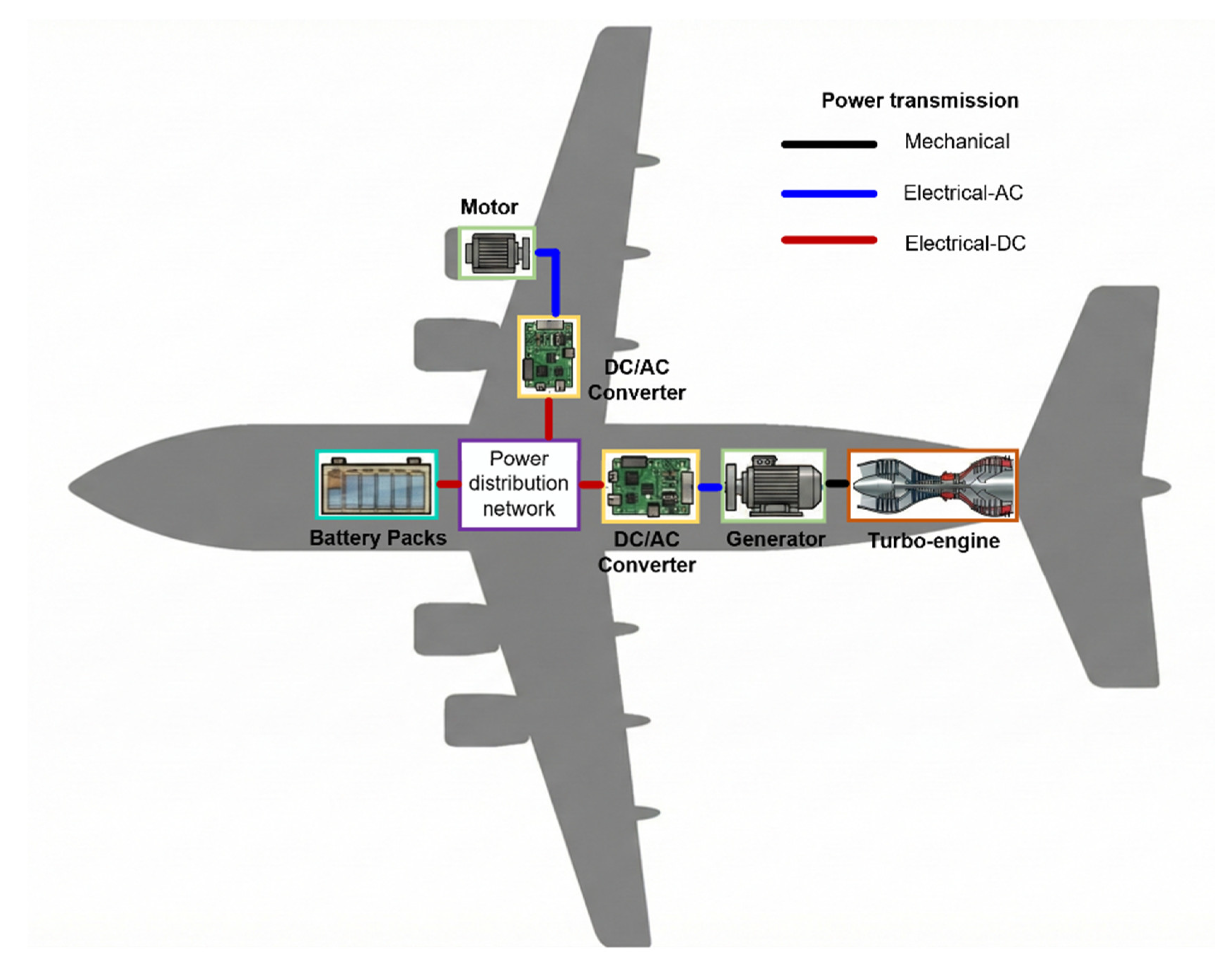
Figure 2.
Stator design of 1MW PM machine using DTP winding layout. (a) Stator core geometry and winding layout. (b) Phase EMF phasor diagram.
Figure 2.
Stator design of 1MW PM machine using DTP winding layout. (a) Stator core geometry and winding layout. (b) Phase EMF phasor diagram.
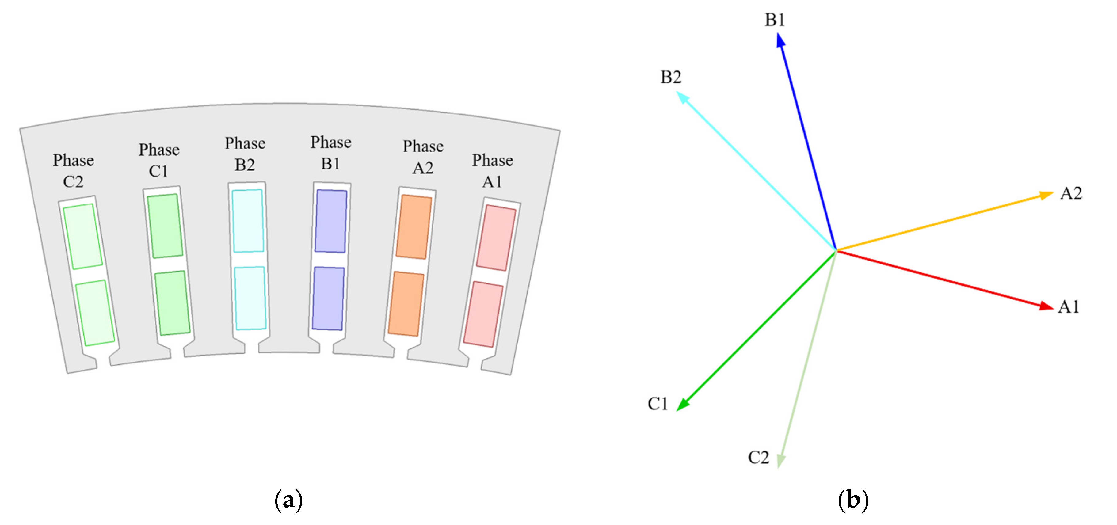
Figure 3.
Drive circuit of the DTP PM machine.
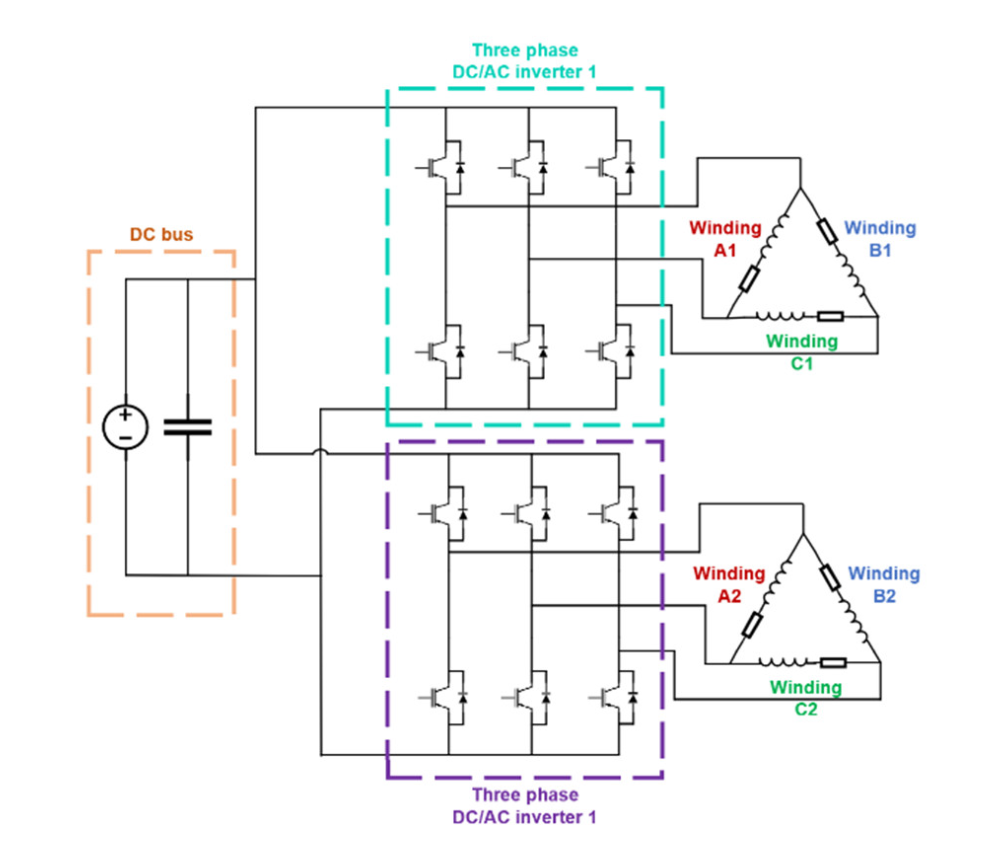
Figure 4.
Rotor geometries and key design parameters of 1MW IPM and SPM benchmark machines. (a) IPM. (b) SPM.
Figure 4.
Rotor geometries and key design parameters of 1MW IPM and SPM benchmark machines. (a) IPM. (b) SPM.
| Parameters | Values |
| Physical air-gap length δ | 1.5 mm |
| Rotor outer radius Rout | 121.5 mm |
| Rotor inner radius Rin | 104 mm |
| PM material | SmCo Recoma 35E [28] |
| Remanence | 1.19 T |
| Iron core material | 35SWY900 [26] |
| Sleeve material (SPM only) | Carbon fiber |
| IPM | |
| Magnet layer | 2 |
| PM1 width Wpm1 | 7.8 mm |
| PM1 height hpm1 | 4 mm |
| PM2 width Wpm2 | 14.8 mm |
| PM2 height hpm2 | 6 mm |
| PM3 width Wpm3 | 3.5 mm |
| PM3height hpm3 | 4.5 mm |
| Volume of PMs | 825360 mm3 |
| Axial segments of PMs | 3 |
| Rotor axial segments | 5 |
| Type of axial stepping | V-shape |
| Mechanical angle between steps | 0.75 degree |
| SPM benchmark | |
| Sleeve thickness hs | 2 mm |
| PM height hpm | 12 mm |
| Rotor back iron thickness hiron | 3.5 mm |
| Axial segments of PMs | 5 |
| Volume of PMs | 1604474 mm3 |
Figure 5.
Von-Mises stress distributions in rotor core at different rotation speed and constant rated 835 Nm torque. (a) 12000 r/min. (b) 15000 r/min. (c) 18000 r/min.
Figure 5.
Von-Mises stress distributions in rotor core at different rotation speed and constant rated 835 Nm torque. (a) 12000 r/min. (b) 15000 r/min. (c) 18000 r/min.
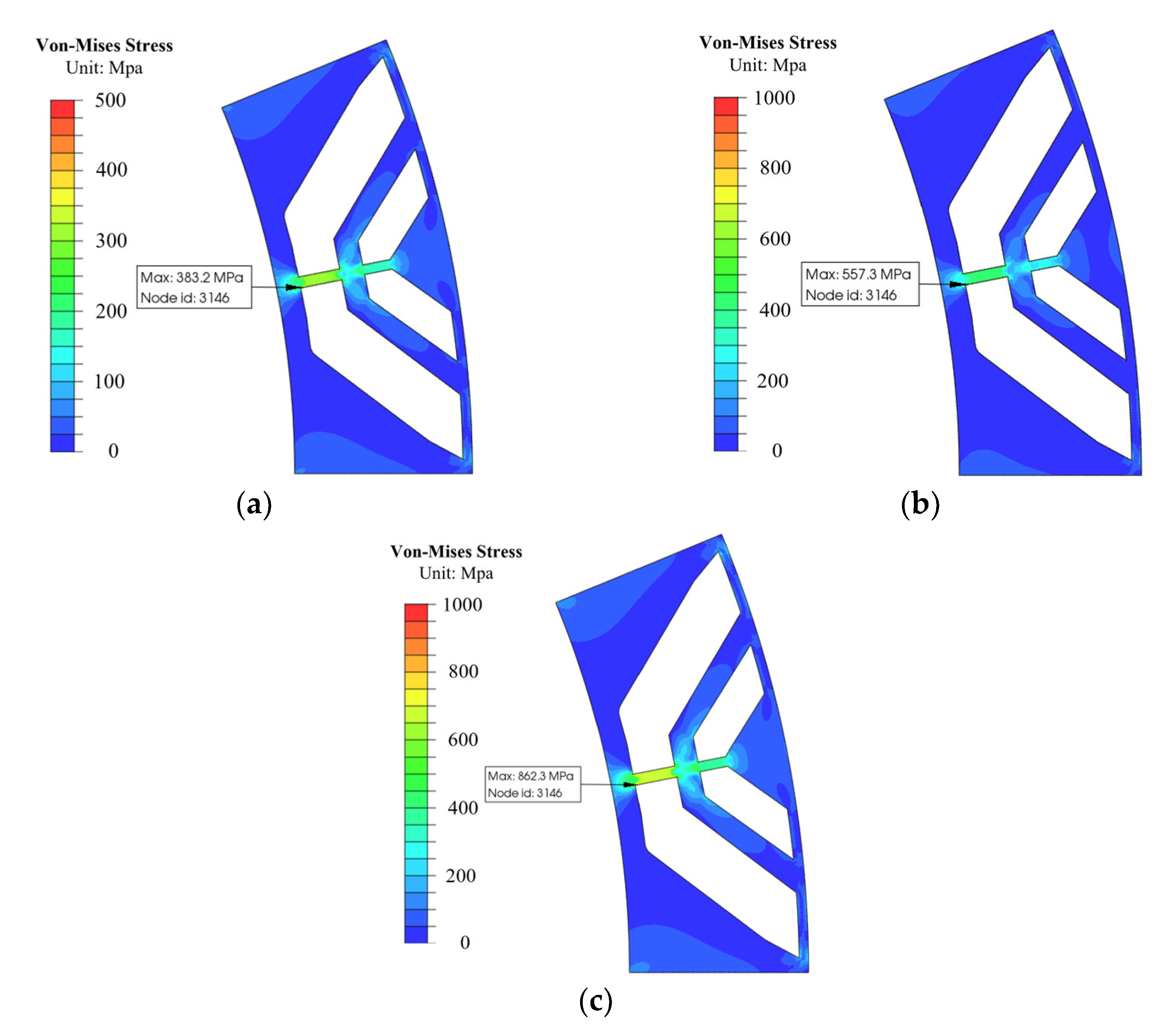
Figure 7.
Distributions of magnetic flux density and flux lines at open-circuit condition. (a) IPM (b) AIPM.
Figure 7.
Distributions of magnetic flux density and flux lines at open-circuit condition. (a) IPM (b) AIPM.
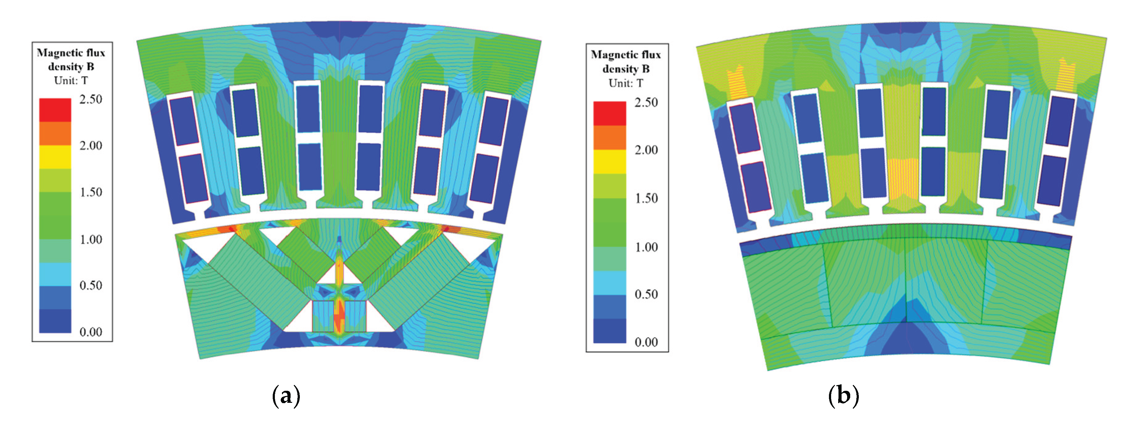
Figure 8.
Comparison of open-circuit air-gap magnetic flux density. (a) Waveform (b) Spectrum.
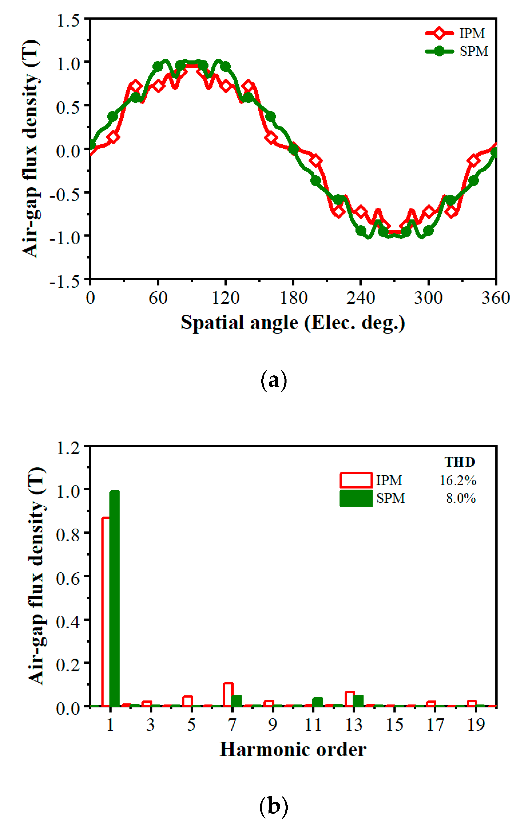
Figure 9.
Comparison of back-EMFs. (a) Waveform (b) Spectrum.
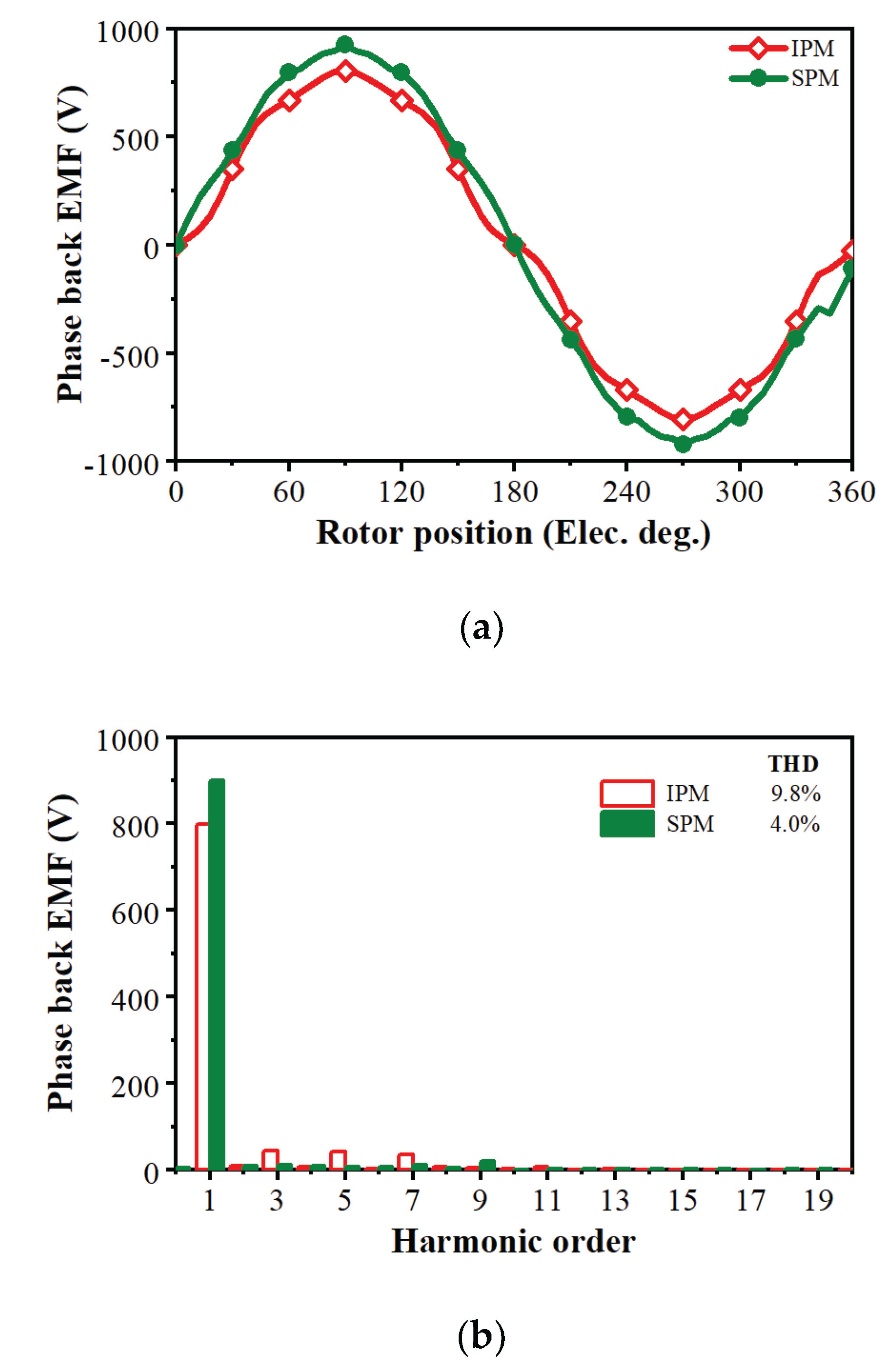
Figure 10.
Comparison of torque-current angle characteristics.
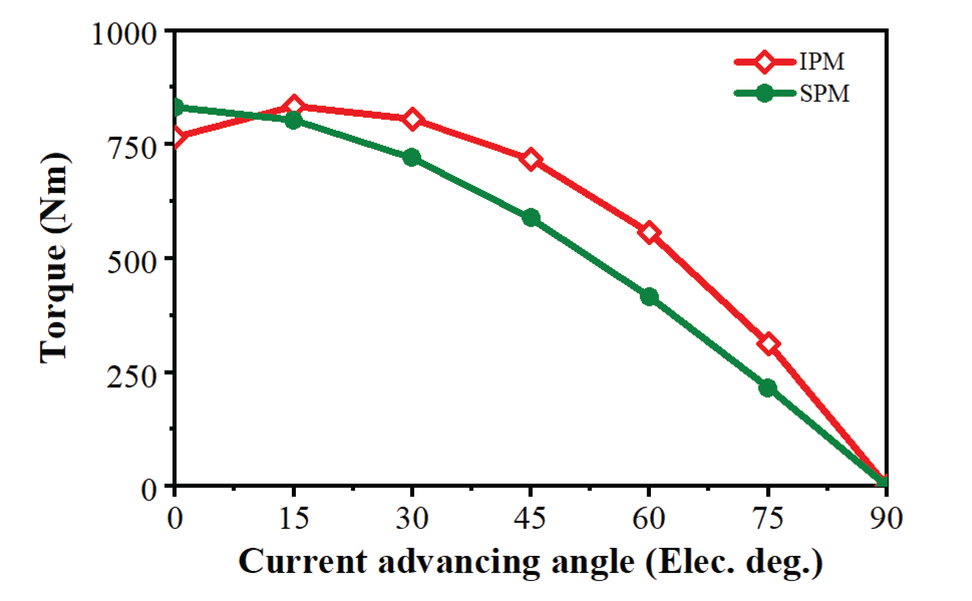
Figure 11.
Extraction of torque-current angle characteristics in IPM machine.
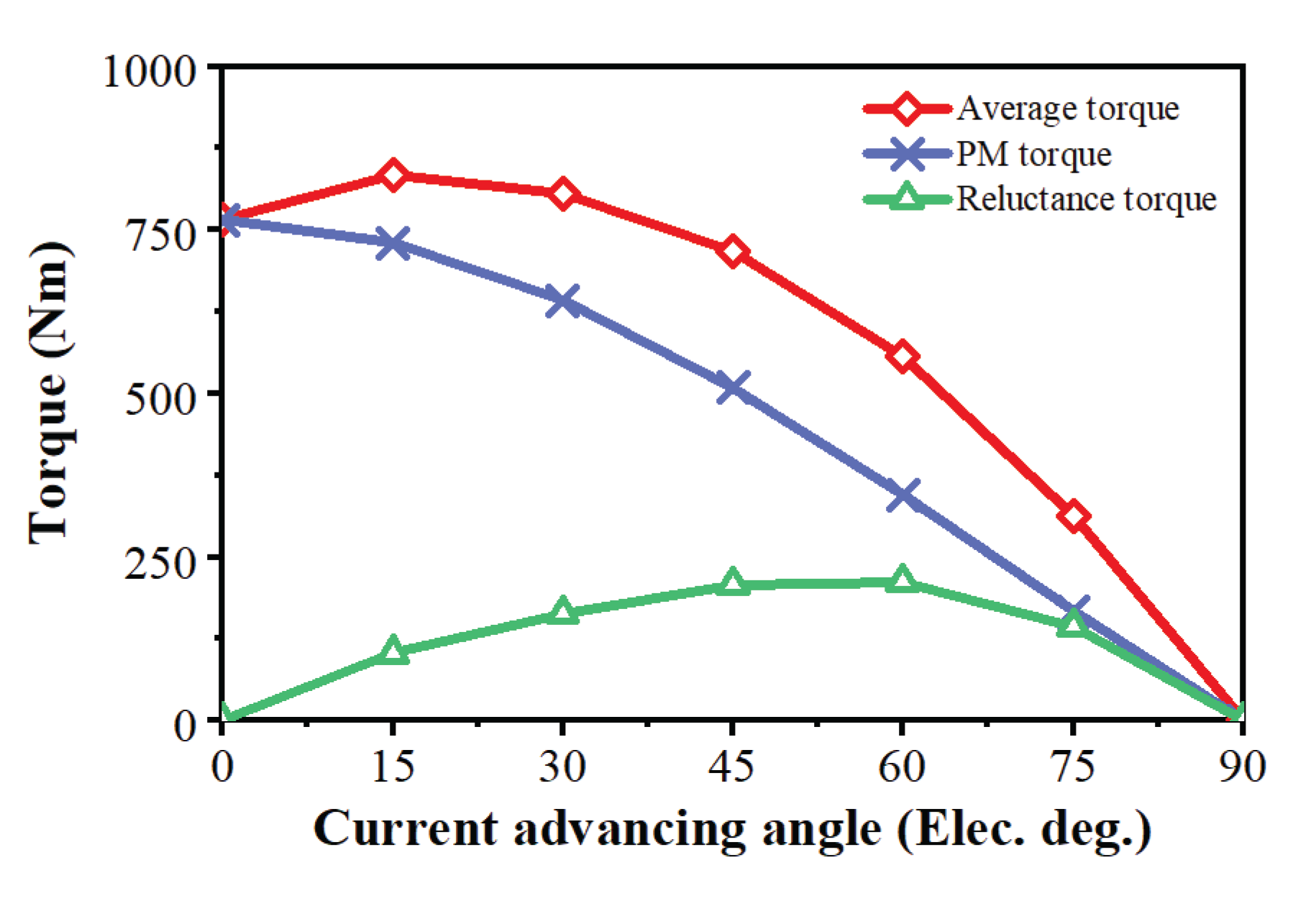
Figure 12.
Comparison of on-load torque performance. (a) Waveform (b) Spectrum.
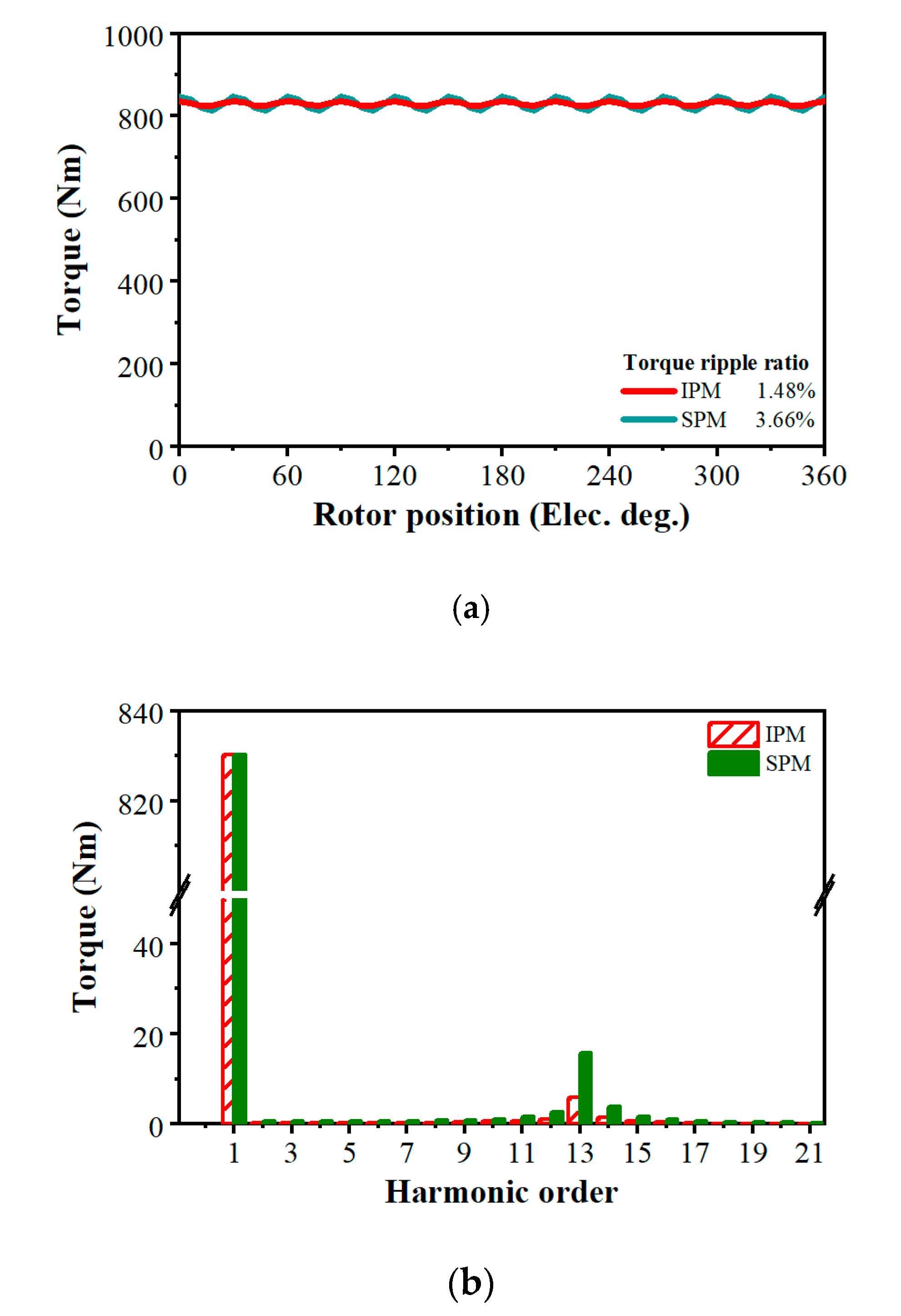
Figure 13.
Comparison of torque-speed performance.
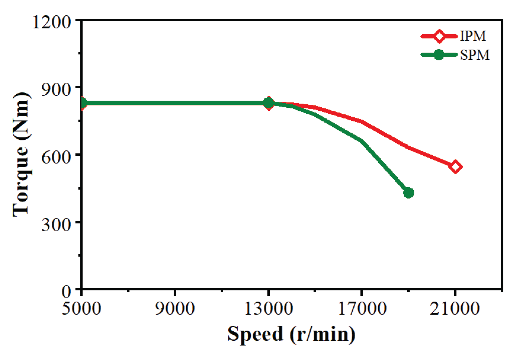
Table 1.
Summary of State-of-the-art MW-class PM Machines.
| Rotor Topology | Winding types | Speed (kr/min) | Power (MW) |
Active power density (kW/kg) | Active torque density (Nm/kg) | Efficiency (%) | Reference |
| Out-rotor SPM |
Litz wire | 12.5 | 1 | 17 | 13.0 | 97.3 | [19] |
| Out-rotor SPM |
Litz wire | 18 | 1 | 14 | 7.43 | >97 | [20] |
| Inner-rotor SPM | Litz wire | 20 | 1 | 23.6 | 11.3 | 96.9 | [21] |
| Inner-rotor SPM | Litz wire | 15 | 2.5 | 24.4 | 15.5 | >99 | [17] |
| Inner-rotor SPM | Litz wire | 15 | 4 | 17.3 | 11.0 | >97 | [8] |
| Inner-rotor SPM | Hairpin winding | 10.8 | 1 | 38.5 | 34.0 | 98.5 | [22] |
| Inner-rotor SPM | Litz wire | 20 | 1 | 23.7 | 11.3 | 97.3 | [23] |
Table 2.
Main specifications of hybrid electrical propulsion generator.
| Parameters | Values |
| Rated power | 1.05 MW |
| Rated speed | 12000 r/min |
| Rated torque | 835 Nm |
| DC bus voltage | 1 kV |
| Number of phases | Dual three phase |
| Number of poles | 16 |
| Stator outer diameter | 300 mm |
| Axial length | <300 mm |
| Active power density | >17 kw/kg |
| Efficiency | >97.5% |
| Mechanical rotor safety factor at rated condition | >2.0 |
Table 4.
Main design parameters of IPM and SPM rotors.
| Parameters | Values |
| Physical air-gap length δ | 1.5 mm |
| Rotor outer radius Rout | 121.5 mm |
| Rotor inner radius Rin | 104 mm |
| PM material | SmCo Recoma 35E [28] |
| Remanence | 1.19 T |
| Iron core material | 35SWY900 [26] |
| Sleeve material (SPM only) | Carbon fiber |
| IPM | |
| Magnet layer | 2 |
| PM1 width Wpm1 | 7.8 mm |
| PM1 height hpm1 | 4 mm |
| PM2 width Wpm2 | 14.8 mm |
| PM2 height hpm2 | 6 mm |
| PM3 width Wpm3 | 3.5 mm |
| PM3height hpm3 | 4.5 mm |
| Volume of PMs | 825360 mm3 |
| Axial segments of PMs | 3 |
| Rotor axial segments | 5 |
| Type of axial stepping | V-shape |
| Mechanical angle between steps | 0.75 degree |
| SPM benchmark | |
| Sleeve thickness hs | 2 mm |
| PM height hpm | 12 mm |
| Rotor back iron thickness hiron | 3.5 mm |
| Axial segments of PMs | 5 |
| Volume of PMs | 1604474 mm3 |
Table 7.
Comparison of active weights between IPM and SPM machines.
| Machine active components | IPM | SPM |
| Stator core (kg) | 25.68 | 25.68 |
| Stator windings (kg) | 6.16 | 6.16 |
| Rotor core (kg) | 11.00 | 4.39 |
| Rotor PMs (kg) | 7.31 | 14.21 |
| Rotor sleeve (kg) | - | 0.23 |
| Total Weight (kg) | 50.15 | 50.67 |
Table 8.
Comparison of on-load performance at rated condition between IPM and SPM machines.
| On-load Performance | IPM | SPM |
| Fundamental phase current RMS (A) | 252 | 246 |
| Current density (A/mm2) | 19.1 | 18.6 |
| Current advancing angle (Elec. Deg.) | 17.4 | 0 |
| Current harmonic ripple (%) | 1.9% | 3.2% |
| Speed (r/min) | 12000 | 12000 |
| Torque, Power, and Power density | ||
| Output torque (Nm) | 831.5 | 830.9 |
| Output power (MW) | 1.045 | 1.044 |
| Torque ripple (%) | 1.48% | 3.66% |
| Active torque density (Nm/kg) | 16.6 | 16.4 |
| Active power density (kW/kg) | 20.8 | 20.6 |
| Losses and Efficiency | ||
| Copper loss (kW) | 7.5 | 7.35 |
| Stator Iron loss (kW) | 14.0 | 12.7 |
| Rotor Iron loss (kW) | 0.50 | 0.08 |
| Magnet loss (kW) | 0.05 | 0.72 |
| Stator side loss (kW) | 21.5 | 20.05 |
| Rotor side loss (kW) | 0.55 | 0.80 |
| Total loss (kW) | 22.05 | 20.85 |
| Efficiency (%) | 97.93 | 98.04% |
Disclaimer/Publisher’s Note: The statements, opinions and data contained in all publications are solely those of the individual author(s) and contributor(s) and not of MDPI and/or the editor(s). MDPI and/or the editor(s) disclaim responsibility for any injury to people or property resulting from any ideas, methods, instructions or products referred to in the content. |
© 2026 by the authors. Licensee MDPI, Basel, Switzerland. This article is an open access article distributed under the terms and conditions of the Creative Commons Attribution (CC BY) license (http://creativecommons.org/licenses/by/4.0/).
Copyright: This open access article is published under a Creative Commons CC BY 4.0 license, which permit the free download, distribution, and reuse, provided that the author and preprint are cited in any reuse.


