

Submitted:
04 February 2026
Posted:
05 February 2026
You are already at the latest version
Abstract
Teatro Nacional de S. João (TNSJ), the main theatre in the city of Porto, was built in 1918. Its architectural design, by architect Marques da Silva, is characterized by a structural sys- tem based on traditional load-bearing masonry walls with large granite blocks. In con- trast, other architectural elements, such as slabs, staircases, and exterior decorative com- ponents, incorporated a then “new” binding material—cement. The richly ornamented façades include a wide range of decorative features, from simple geometric motifs to floral elements and large-scale masks. These elements were constructed around steel frame- works and executed using mortars with a probable cementitious binder. Due to their high level of exposure, the façades of TNSJ were subject to repeated interventions. Neverthe- less, significant degradation was observed over time, including the detachment and fall of mortar from decorative elements, which highlighted the need for further conservation actions. In this context, the façades were systematically inspected, and representative sam- ples were collected to characterize material constituents, establish mix proportions, and identify the extent and causes of deterioration. Analytical techniques—including X-ray diffraction, acid dissolution, and optical microscopy—were employed to determine mor- tar composition, while capillary water absorption and mechanical strength tests were con- ducted to assess mortar properties. The results indicated that mortar carbonation and the presence of salts, likely associated with marine aerosol exposure, promoted the oxidation of embedded metallic elements, leading to the progressive degradation of the surrounding mortars.
Keywords:
20th century architecture
; cement
; lime
; mortars
; characterization
1. Introduction
Teatro Nacional de São João (TNSJ), classified as a national monument, is the main theatre in the city of Porto (Portugal), located in Batalha Square, in the historical centre. The history of TNSJ began in 1794, when Francisco de Almada e Mendonça, the main authority of Porto, agreed with the project for an opera house designed by Italian architect Vicente Mazzoneschi. The original theatre was built between 1796 and 1798, but was soon afterwards, in 1908, destroyed by a fire [1]. A new building for the same theatre, TNSJ, was built in 1918 [1]; Architect José Marques da Silva was responsible for the project, and the output did not have a noticeably modern architecture (Figure 1). At the beginning of the 20th Century, in Portugal and specifically in the region of Porto, traditional construction prevailed, with load-bearing granite walls and air lime mortars. Despite this, the use of hydraulic binders and especially of cement, that had started in England and France, had widespread throughout Europe [2,3], and in Portugal it is possible that it started to be used in buildings of some importance. The architect chose a mixed, somewhat audacious solution, using stone walls and cement-based concrete for structural elements, such as slabs and beams. It seems probable that Marques da Silva also chose cement as the main binder for mortars of the external ornaments and this constitutes one of the expected results of this study. These elaborate ornaments extremely varied in size and shape, portraying floral arrangements, geometric patterns, masks or the human figure, were built around a steel frame that was used as a basis for the various forms. Almost one century after its construction, TNSJ had a major intervention in the external facade, which was carried out in the period of 1993 to 1995 [4]. However, despite this, in 2006 the state of the mortar ornaments was precarious, with severe cracks and material loss. This paper describes the study of mortars from these ornaments using analytical techniques and attempts to explain the reasons for such severe degradation. A complete set of analysis and tests was carried out to characterize the mortars and enable the development of compatible mortars for restoration purposes.
Exposure conditions of this monument are high as Porto is a seaside city and the monument is at a high spot in the city centre. Temperatures are mild and medium values are within the range of 6-25ºC (6-15ºC in Winter and 14-25ºC in Summer). Rainfall is common throughout all months of the year, with predominance from October to January and fog is also present on many occasions.
2. Sampling and Testing Procedures
2.1. Sampling
Sampling was performed on 3 different facades (East, West and North) of TNSJ building. Designations for the samples incorporate these locations – Pri (main Nort façade); Po (West façade); P (East façade). This paper will focus its study on six representative samples FPo-2, FPo-8, FPo-10, FPri-A1P1, FPri-PB and FN-V2P1 which were withdrawn considering different ornamental structures as is represented in Figure 2a-f.
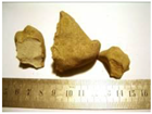
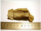
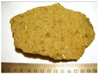
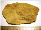
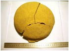
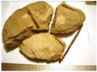
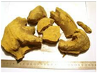
Three mortar samples were withdrawn from the western facade (FPo-2, FPo-8 and FPo-10); two were collected from the northern facade (FPri-A1P1 and FPri-PB) and from the eastern one (FN-V2P1), as illustrated in Table 1. In case of FPo-10 and FPri-A1P1 samples, two different mortars (lighter and darker) were distinguished and analyzed separately as FPo-10a, FPo-10b and FPri-A1P1a, FPri-A1P1b, respectively. Mortars with “a” designation are more outwardly and therefore more exposed than those with “b” designation.
2.2. Testing Procedures
The employed methodology took into account current methods for the testing of historical mortars [6]. To characterise the sampled mortars, the following analytical methods and tests were used:
X-Ray Diffraction (XRD) provided qualitative information on the crystalline mineral phases existent in the samples. For this analysis, mortars were crushed and dried at a low temperature. This analysis was performed on the fraction below 75µm to allow a more thorough analysis of the binder. The equipment used was a Panalytical X-Pert Pro X-Ray Diffractometer.
Acid dissolution was performed based on ASTM-C 25-11e1 [7] and by the methodology suggested by some authors [8,9] to dissolve carbonates (calcite, magnesite and dolomite) and create a residue composed by the aggregate fraction. Hydrochloric acid was used to guarantee a residue composed mainly by siliceous sand. Results give an approximate value of binder/aggregate ratio, as the used acid dissolution technique dissolves carbonates and partially dissolves soluble silica. The obtained residue was dried until constant mass was achieved. Particle size distribution by dry sieving was performed on the residue obtained from acid dissolution according to standard BS 3406-2 [10].
Thin sections and polished surfaces were prepared by impregnation in epoxy resin and observed with petrographic polarizing microscope Zeiss Axioplan 2 equipped with x10 oculars and x1,25-x100 objectives. Photographs were taken with a digital camera model Infinity X from DeltaPix.
Compressive strength tests were carried out based on the method proposed in “Characterization of mechanical properties of historic mortars – testing of irregular samples” [11] on a SHIMADZU: AG-IC 100 kN equipment, with loads of 10 and 50 kN/s.
The capillary water absorption test was carried out as described in the paper “Capillary tests on historic mortar samples extracted from site. Methodology and compared results” [12]. Subsequently mortars were dried following procedure based on standard NORMAL 29/88 [13].
Degree of carbonation was measured with a phenolphthalein solution (1%) and based on ICCROM’s ARC test description [14].
3. Results and Discussion
3.1. Mortar Composition
3.1.1. X-Ray Diffraction Analysis
X-Ray diffraction analysis (XRD) analysis provided an insight on mineralogical composition of individual mortars (Figure 3). XRD patterns show that calcite and quartz are dominant minerals in all the samples with exception of FPo-2 mortar. Gypsum and feldspars are present in the most of the cases (FN-V2P1, FPri-PB, FPri-A1P1a, FPri-A1P1b, FPo-10a) and (FN-V2P1, FPri-PB, FPri-A1P1a, FPri-A1P1b, FPo-10b, FPo-8, respectively), while mica is identified only in case of FPri-A1P1a and FPri-A1P1b mortars and magnesite in FPri-A1P1b (Figure 3). All the samples (besides FPo-2) display the presence of halite (NaCl). Other soluble salts such as nahcolite (NaHCO3) and natron (Na2CO3·10H2O) were identified, nahcolite in the samples FPri-A1P1a,b and FPRi-PB, all from the northern façade, and natron was present in FPri-A1P1a mortar. The presence of salts, sometimes quite meaningful, reveals that mortars were relatively altered from their original composition. The occurrence of natron and nahcolite is usually related to their formation in concrete or mortars under the action of sodium carbonates [15]. Current studies have revealed that the action of sodium carbonate usually results in salt crystallization inside voids in the mortar matrix, while the action of sulphates may be more destructive, often promoting concrete delamination [15]. The presence of kaolinite in FPri-A1P1a, due to the alteration of feldspars, may be another indicator of the high degree of alteration of these mortars or simply a result of use of sand with incorporation of kaolin (Figure 3). Moreover, related to the differences between FPo-10a and FPo-10b and FPri-A1P1a and FPri-A1P1b mortars, it is noticeable that the mortars differ in their “a, b” subgroups exclusively only in the intensities of the peaks of the admixtures. Lower occurrence of gypsum in case of FPri-10b and mica, kaolinite, gypsum and natron in case of FPri-A1P1b mortar is confirmed, compared to FPri-10a and FPri-A1P1a mortars, respectively, as expected due to their distinct exposure.
FPo-2 mortar reveals a clearly different mineralogical composition compared to the rest of the mortars, proving a dissimilar origin of this sample. The main crystalline phase in FPo-2 is portlandite, which partially carbonated into the calcite form. Other identified admixtures include quartz, dolomite and belite (C2S). This mortar does not contain any soluble salts (Figure 3). Existence of portlandite and C2S and absence of soluble salts in FPo-2 confirms that this mortar was applied during the former intervention rather than during the initial building phase. Although, solely from XRD results the type of binder used remains unclear, XRD reveals similarities and distinctions between mortars and clearly identifies salts present in these samples.
3.1.2. Acid Dissolution of Mortars
Acid dissolution of mortars results in approximate binder:aggregate proportion in weight, taking into account that siliceous sand was used as an aggregate. Two main weight ratios are identified, 3:7 for samples FPo-8, FPo-10b, FPri-A1P1a, FPri-A1P1b and 2:3 for FPo-10a, FPri-PB and FN-V2P1 (Table 2). A singular case of a weight ratio of 1:1 is encountered in a specific mortar withdrawn from an ornament in the western facade (FPo-2), with a clearly distinctive appearance. Singularity of FPo-2 mortar was proved also by XRD analysis (Figure 3). Acid dissolution of this particular mortar created saponification which may be due to the presence of water repellent agents.
No relation between different ratios and different types of ornaments or different facades was found. However, according to variations in binder: aggregate ratio, two group of mortars are identified, presumably belonging to the same construction phase (FPo-8, FPo-10b, FPri-A1P1a, FPri-A1P1b and FPo-10a, FPri-PB,u FN-V2P1) and a singular mortar is ruled out as belonging to a posterior intervention (FPo-2).
3.1.3. Particle Size Distribution of Aggregates
Particle size distribution of aggregates, performed on the residue obtained from acid dissolution, shows some variation, suggesting that sand from different sources may have been used. Figure 4 shows the curves of the studied mortars, clearly portraying this variety. Although there is no relation between particle size distribution of the aggregates and different mortar compositions or ratios, mortar FPo-2 displays a distinctive aggregate mainly composed of fine sand in comparison to the coarser aggregate used in the other mortars (Figure 4). The rest of the samples are divided according to their particle size into 3 groups:
1) samples FPo-8, FPo-10b and FPri-A1P1b with finer particles,
2) samples FPri-PB and FN-V2P1 with larger particles,
3) samples FPo-10a and FPri-A1P1a, with distinct particle size distribution compared to the rest of samples. FPri-A1P1a mortar is the one with coarsest particle size (Figure 4).
Visual analysis of the aggregates allows further insight on similarities of the mortars, as is illustrated in Figure 5.
Distinct character of FPo-2 is noticeable also in the fineness and color of its aggregate, composed of fine brownish sand in comparison to the river sand aggregate used in the other mortars.
A similar sand, with distinct particle size distribution was used for the remaining mortars. Considering particle size distribution, the same aggregate was used in the composition of mortars FPo-10b and FPri-A1P1b and FPo-8. The same conclusion may be applied to samples FPri-PB and FN-V2P1 (Figure 4).
From the obtained results and coupling with XRD data, it is possible that FPri-A1P1a and FPriA1P1b mortars together with FPo-10a and FPo-10b were prepared and used at the same period, with the specific aim of fulfilling two layers, as the basis of aggregate of individual set is the same accompanied by coarser grains (Figure 5).
3.1.4. Thin Section Analysis
Thin section analysis of the mortars provided further insight related to the binder composition. Results from thin section analysis showed similarities for all the samples and therefore FPo- 10 was analysed (Figure 6).
Optical microscopy revealed clear evidence of cement grains, composed by alite (C3S), belite (C2S) and ferrite (C4AF) as displayed in Figure 6, confirming that this binder was actually used in the mortars of Teatro Nacional de S. João facades.
Natural cement began to be used in Europe around the end of the 19th, beginning of the 20th Century [19, 20] and it is possible that this material was adopted by Marques da Silva, who had studied abroad and wan keen on introducing foreign innovation. Air lime was also present, suggesting a lime/cement mix. This analysis also provided information on the type of aggregate, confirming the use of river sand of granitic origin in the composition.
3.2. Mortar Characteristics
3.2.1. Compressive Strength and Capillary Coefficient
Compressive strength tests were performed on 30 mm x 30 mm cubes from the extracted samples as this was the maximum size possible. This testing was possible to accomplish only on two mortars: FPo-8 and FN-V2P1, due to the sample size.
Compressive strength values were of 16.6 to 38.9 MPa. The high values are only compatible with cement mortars, but seem to indicate that, although the mortars have been affected by the action of soluble salts, this did not affect their mechanical strength. The salts encountered were mainly halite, nahcolite and natron and they may have filled an initially porous mortar structure (Figure 3).
Capillary coefficient values range from 0.034 kg/m2.min0.5 and 0.048kg/m2.min0.5. These values are very low and only compatible with mortars with low porosity, such as cement mortars [12,16].

Table 3.
Compressive and capillary coefficient of mortars.
| Mortar | Compressive strength (MPa) |
Capillary coefficient (kg/m2.min0.5) |
|---|---|---|
| FPo-8 | 16.6 | 0.034 |
| FN-V2P1 | 38.9 | 0.048 |
3.2.2. Carbonation Depth
The determination of carbonation depth was carried out on site, where the mortars were extracted and, in the laboratory, on freshly cut mortar surfaces. On site spraying of a phenolphthalein solution on surfaces next to the steel structure, immediately after mortar extraction, showed complete carbonation and laboratorial testing revealed a carbonation depth of up to 7 cm corresponding to the maximum mortar thickness over the steel structure. In depth carbonation of concrete and mortar may be caused by long environmental exposure [17] and may occur concrete or cement mortars under intense environmental strain. A porous structure and weather conditions such as rain and fog are factors that enhance this effect. This is exactly the case of TNSJ façade characteristics and exposure.
3.3. Mortar/Steel Frame Interface
Polished surfaces of the steel/mortar interface were viewed under the optical microscope to evaluate the effect of corrosion. The mortar thickness over the steel structure varied extremely, ranging from barely a few mm to 6 to 7 cm. Figure 7 depicts the lack of cohesion between mortar and steel and the corrosion of the steel frame.
Mortar carbonation was extensive, reaching the steel frame, due to environmental action and possibly porous mortars at an initial stage. This led to steel depassivation and consequent corrosion and expansion of the steel frame. This fact created the main problems in the various ornaments in TNSJ facades, as the stresses produced by the volume increase of the steel frame created generalized cracking in mortars and lack of cohesion between the mortar and the steel. Mortars over the steel frame are almost loose and prone to detachment.
4. Conclusions
Mortar samples were extracted from decorative elements of external facades of national monument Teatro Nacional de S. João (TNSJ). Analysis provided the following results:
1. Mortar composition displays two main binder: aggregate ratios: 2:3 (FPo-10a, FPri-PB, FN-V2P1) and 3:7 (FPo-8, FPo-10b, FPri-A1P1a, FPri-A1P1b). Predominant minerals in the mortars are calcite and quartz in most of the samples (and portlandite in a single case). The aggregate is a siliceous sand of granitic origin with distinct particle size distribution.
2. Thin section analysis confirmed use of natural cement and air lime as binders. It also confirmed the type of sand.
3. Mortar characteristics such as compressive strength, which is high, and low capillary water absorption are only compatible with the use of cement as a binder, confirming the results of composition analysis.
4. Salt content is clear, in the form of halite, gypsum, natron and nahcolite and is the direct result of long-term exposure. However, this fact did not negatively affect the mortars’ mechanical characteristics and could instead have contributed towards a more compact structure by salt crystallization inside mortar voids. Undoubtedly carbonation also increased mortar compactness, and all analysed mortars were completely carbonated at a depth corresponding to the position of the steel structure.
5. Main causes for degradation were mortar thickness over the steel frame and environmental exposure. Mortars were moulded around steel structures that acted as a basis for shape, but the mortar thickness over the steel structure was extremely varied, ranging from barely a few millimetres to 6 to 7 centimetres. This fact promoted steel degradation, but depassivation also occurred by extensive carbonation of the mortars after a long exposure to external conditions. The steel structure is profoundly affected and its volume increase by corrosion created widespread cracking in the external ornaments, promoting further degradation.
6. FPo-2 mortar differs from the rest, both in terms of mineralogical composition and binder: aggregate ratio suggesting that it may have been used in a conservation action and is clearly not an original mortar.
Study of early 20th Century mortars is crucial towards the adequate conservation of buildings from this specific time, many of which need intervention. This experimental architectural solution was used in various other cases. Mortars made with natural cement or lime/cement mixes must be repaired with hydraulic binders with similar characteristics (physical and mechanical) as those of the original mortars. Decisive factors for success in this intervention are high mortar pH and suitable coating thickness, whenever steel frames were used.
References
- Available online: https://www.answers.com/topic/s-o-jo-o-national-theatre.
- Callebaut, K.; Elsen, J.; Van Balen, K.; Viaene, W. Nineteenth century hydraulic restoration of mortars in the Saint Michael’s Church (Leuven, Belgium). Natural hydraulic lime or cement? Cement and Concrete Research 2000, 31, 397–403. [Google Scholar] [CrossRef]
- Souponitski, S.Z.; Sniatkov, S.V.; Grigoriev, S.E. Early reinforced concrete constructions in Russia: specific faults and causes of failure. Engineering Failure Analysis 2001, 8, 201–212. [Google Scholar] [CrossRef]
- Available online: https://www.porto24.pt/memoria/teatro-nacional-sao-joao-historia-de-um-edificio-de-cultura/ (in portuguese).
- Available online: https://www.caravelas.com.pt/Porto_T_Sao_Joao.jpg.
- Velosa, A.L.; Veiga, R.; Coroado, J.; Ferreira, VM; Rocha, F. Characterization of ancient mortars from Roman times to the nineteenth century’ in Compatibility issues of new mortars with substrates and ancient mortars, Materials, Technologies and Practice in Historic Heritage Structures; Bostenaru Dan, Maria, Prikryl, Richard, Török, Ákos, Eds.; Springer: Berlin, 2010; pp. 235–257. ISBN 978-90-481-2683-5. [Google Scholar]
- ASTM C25-11e1; Standard Test Methods for Chemical Analysis of Limestone, Quicklime, and Hydrated Lime. ASTM International: West Conshohocken, PA, 2011.
- Alvarez, J.I.; Martín, A.; Casado, P.; García, J.; Navarro, I.; Zornoza, A. Methodology and validation of a hot hydrochloric acid attack for the characterization of ancient mortars. Cement and Concrete Research 1999, 29, 1061–1065. [Google Scholar] [CrossRef]
- Jedrzejewska, H. Old Mortars in Poland: A New Method of Investigation. Studies in Conservation 1960, 5(4), 132–138. [Google Scholar] [CrossRef]
- BS 3406-2; Methods for determination of particle size distribution, Recommendations for gravitational liquid sedimentation methods for powders and suspensions. British Standard Institute: London, 1986.
- Valek, J.; Veiga, M.R. Characterization of mechanical properties of historic mortars – testing of irregular samples. Advances in Architecture Series 2005, 20, 365–374. [Google Scholar]
- Veiga, M.R.; Fragata, A.; Velosa, A.L.; Magalhães, A.C.; Margalha, G. Lime-Based Mortars: Viability for use as substitution renders in historical buildings. International Journal of Architectural Heritage 2010, 4, 177–195. [Google Scholar] [CrossRef]
- Commisione Normal, 1991, Misura dell´indice di asciugamento, Roma CNR/ICR 29/88.
- Teutonico, J.M. A laboratory manual for architectural conservators; ICCROM: Rome, 1988. [Google Scholar]
- Haynes, H.; O'Neill, R.; Neff, M.; Mehta, P.K. Salt Weathering of Concrete by Sodium Carbonate and Sodium Chloride. ACI Materials Journal 2010, 107, 255–266. [Google Scholar] [CrossRef]
- Faria, P.; Henriques, F.; Rato, V. Comparative evaluation of lime mortars for architectural conservation. Journal of Cultural Heritage 2008, 9, 338–346. [Google Scholar] [CrossRef]
- Bertolini, L.; Carsana, M.; Redaelli, E. Conservation of historical reinforced concrete structures damaged by carbonation induced corrosion by means of electrochemical realkalisation. Journal of Cultural Heritage 2008, 9, 376–385. [Google Scholar] [CrossRef]
- Seir, T. Tyndslib med hydraulisk kalkmørtel, Rapport R121205, (2013) 34 pages (in Norwegian).
- Gosselin, Christophe; Vergès-Belmin, Véronique; Royer, A.; Martinet, G. Natural cement and monumental restoration. Materials and Structures/Materiaux et Constructions 2009, 42. [Google Scholar] [CrossRef]
- Figueiredo, C., Pimenta do Vale, C., Veiga, M.R. Santos Silva, A., Vieira, M., Tavares, A., Velosa, A. (2019) Natural cement in Portuguese heritage buildings, Materiais 2019, Universidade Nova, 14-17 April.
Figure 1.
Nacional Theatre de S. João, photograph in an old postcard.
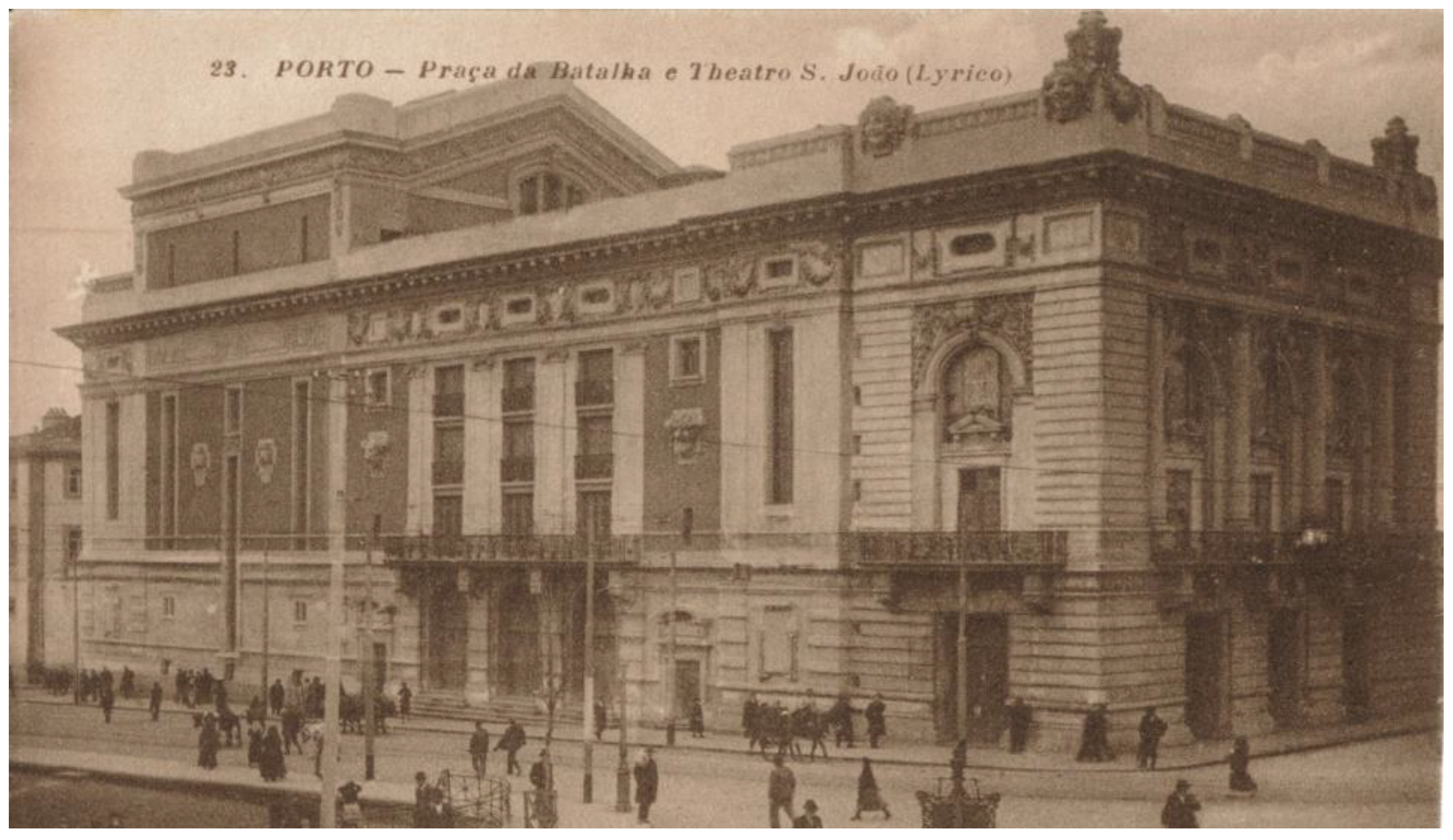
Figure 2.
Sampling performed on facades of TNSJ. Samples: a), b) FPo-2 Polymorphic motif (Zone evidently subjected to recent intervention, sample drawn by hand); c) FPo-8 Mask; d) FPo-10 Geometric ornament; e) FPri-A1P1 Frieze; f) FPri-PB Frieze, bottom part; g) FN-V2P1 Flower ornament.
Figure 2.
Sampling performed on facades of TNSJ. Samples: a), b) FPo-2 Polymorphic motif (Zone evidently subjected to recent intervention, sample drawn by hand); c) FPo-8 Mask; d) FPo-10 Geometric ornament; e) FPri-A1P1 Frieze; f) FPri-PB Frieze, bottom part; g) FN-V2P1 Flower ornament.
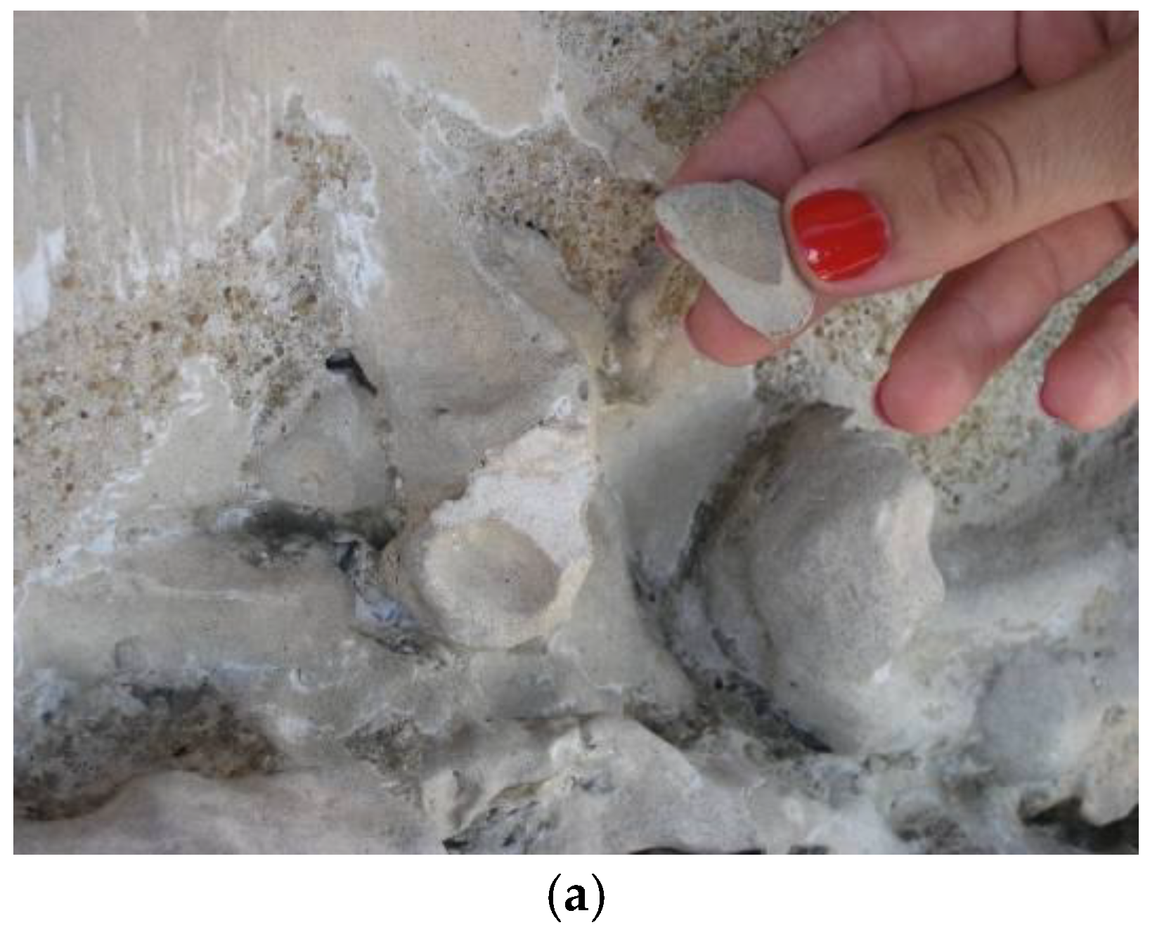
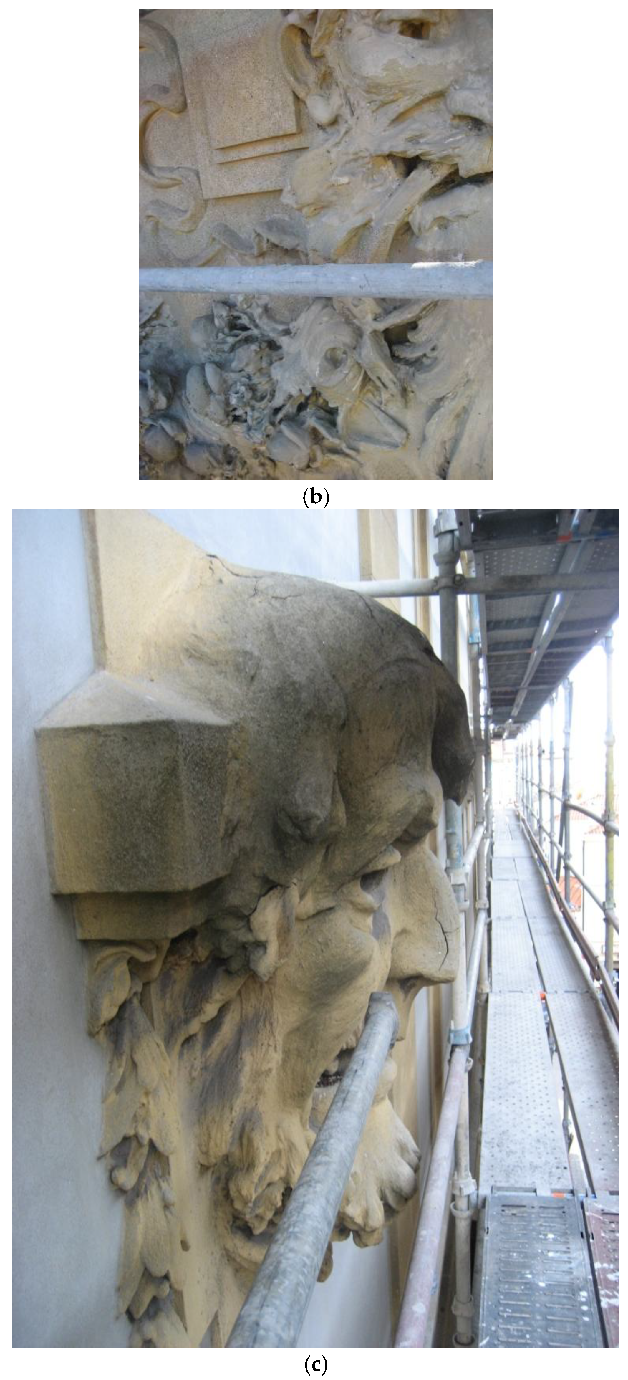
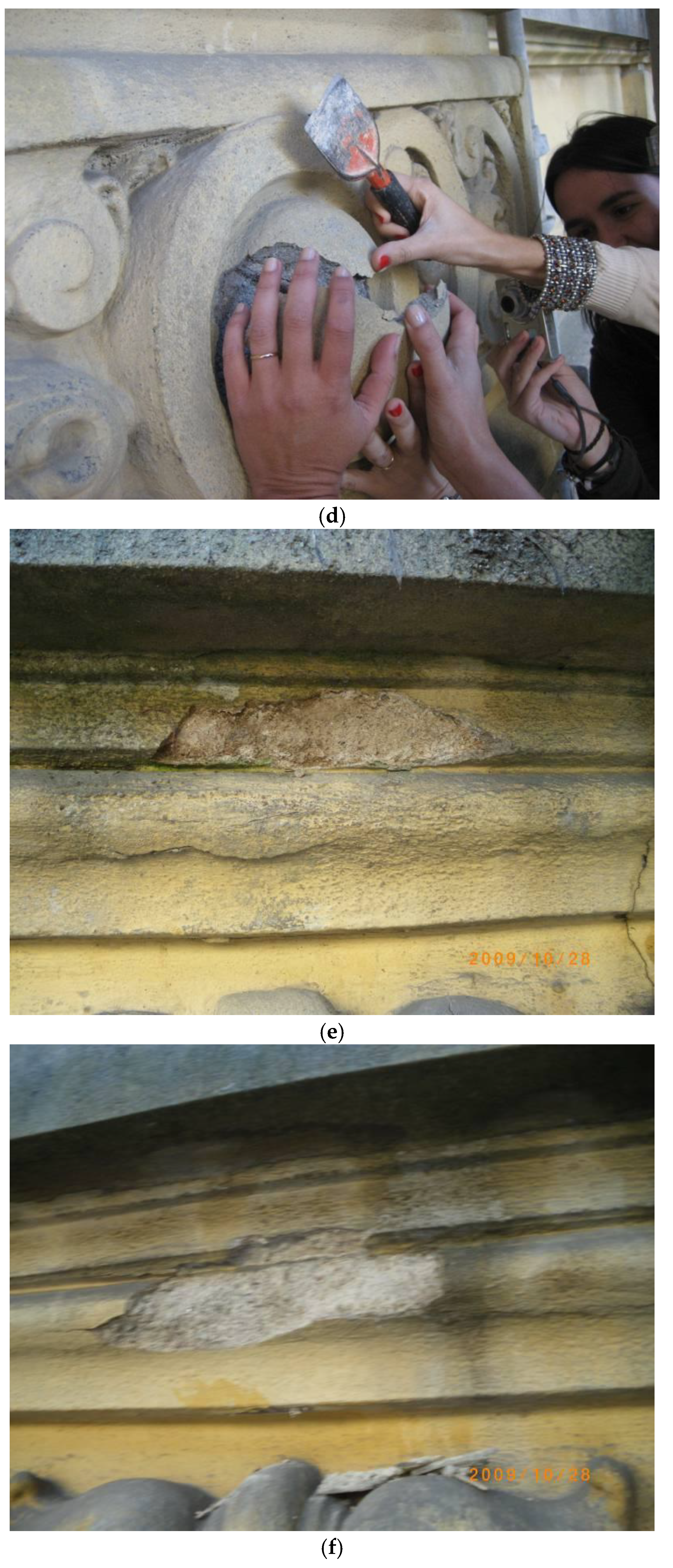
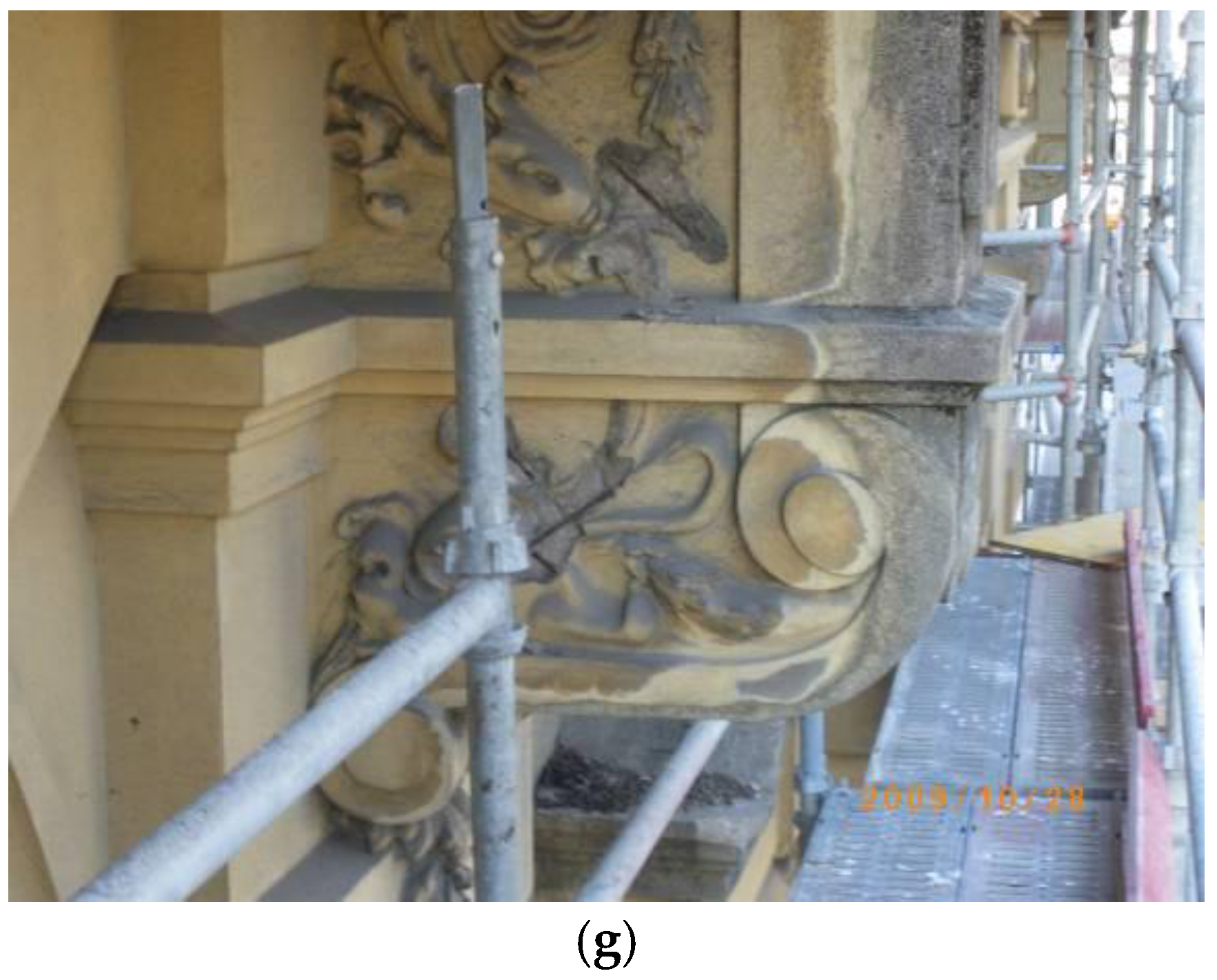
Figure 3.
XRD patterns of the studied mortars. (B-belite, C-calcite, D-dolomite, F-feldspar, G-gypsum, H-halite, K-kaolinite, M-mica, Ms-magnesite, N-nantron, Na-nahcolite, P-portlandite, Q-quartz).
Figure 3.
XRD patterns of the studied mortars. (B-belite, C-calcite, D-dolomite, F-feldspar, G-gypsum, H-halite, K-kaolinite, M-mica, Ms-magnesite, N-nantron, Na-nahcolite, P-portlandite, Q-quartz).
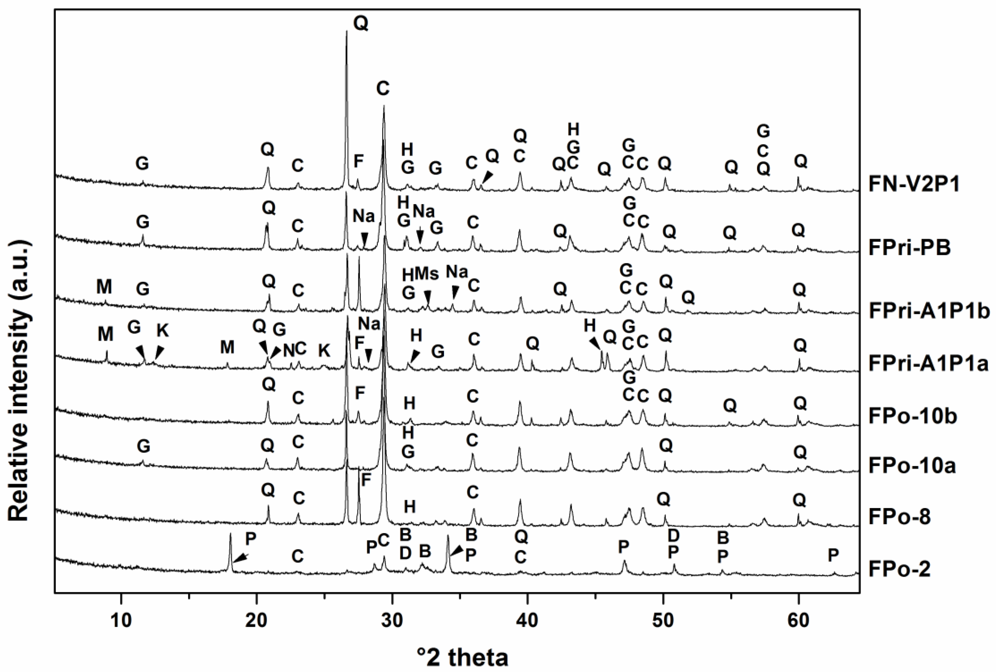
Figure 4.
Particle size distribution of mortars aggregates.

Figure 5.
Insoluble fraction of individual mortars obtained after acid dissolution (a) FPo-2, b) FPo-8, c) FPo-10a, d) FPo-10b, e) FPri-A1P1a, f) FPri-A1P1b, g) FPri-PB, h) FN-V2P1.
Figure 5.
Insoluble fraction of individual mortars obtained after acid dissolution (a) FPo-2, b) FPo-8, c) FPo-10a, d) FPo-10b, e) FPri-A1P1a, f) FPri-A1P1b, g) FPri-PB, h) FN-V2P1.
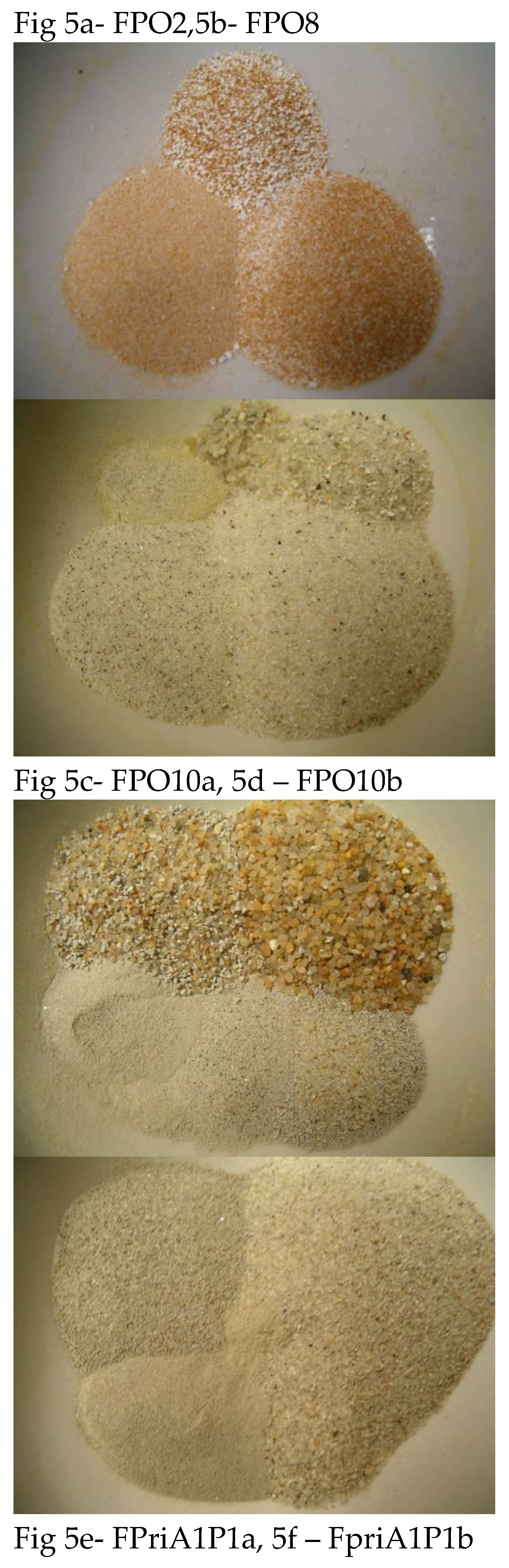
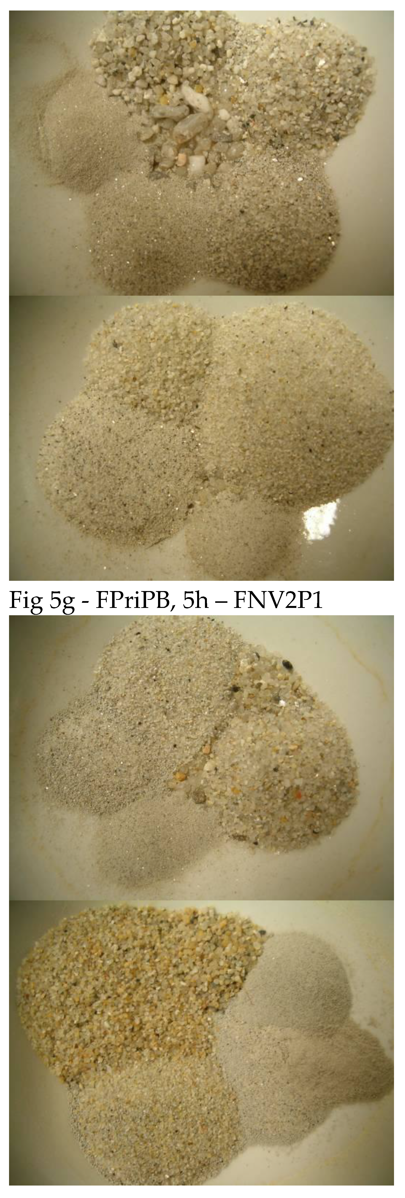
Figure 6.
Thin section of FPo-10 mortar. (PC- cement, L-lime) [18].
Figure 6.
Thin section of FPo-10 mortar. (PC- cement, L-lime) [18].
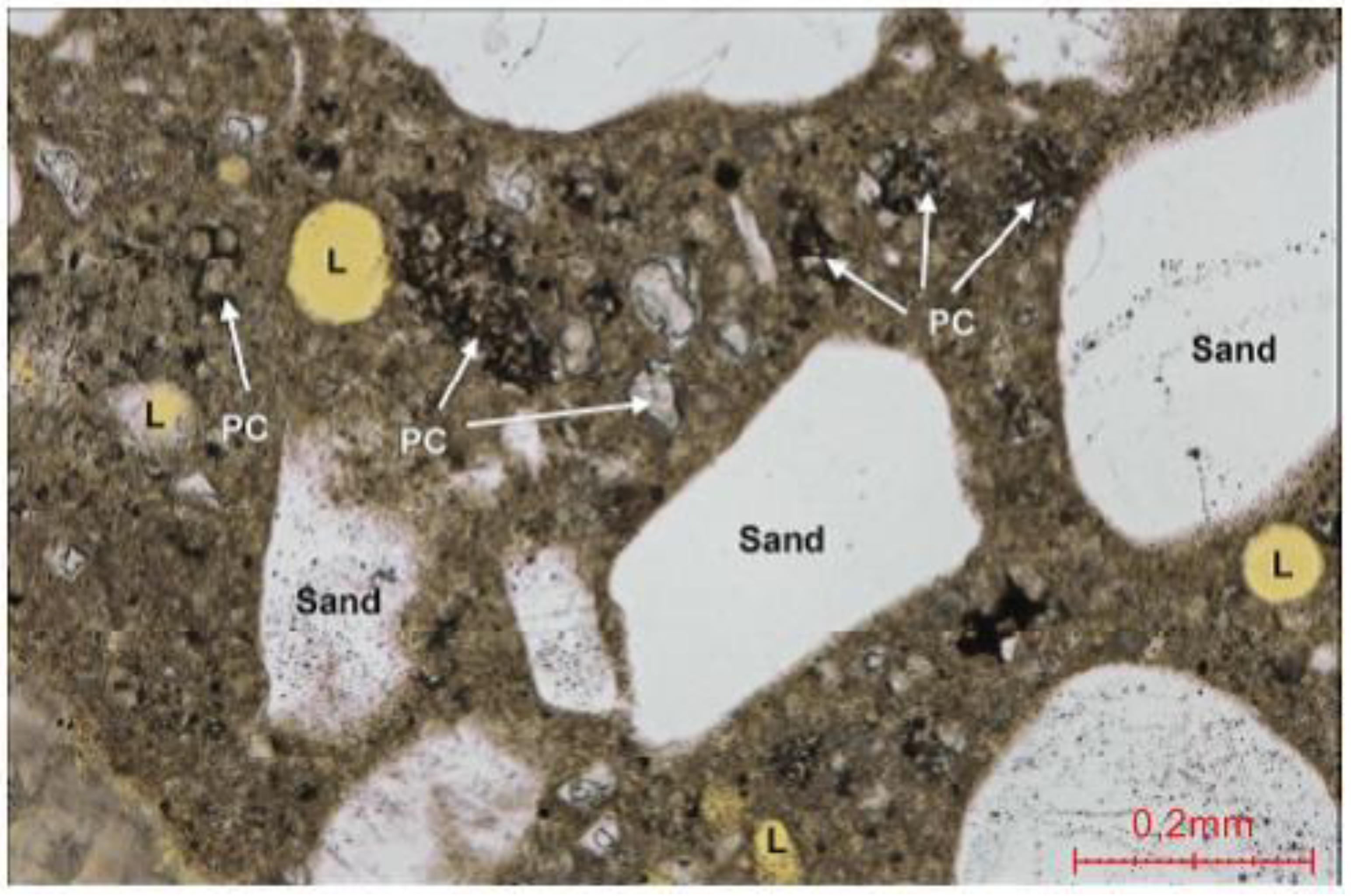
Figure 7.
Steel structure/mortar interface showing strong discontinuity and steel corrosion FPo-8.
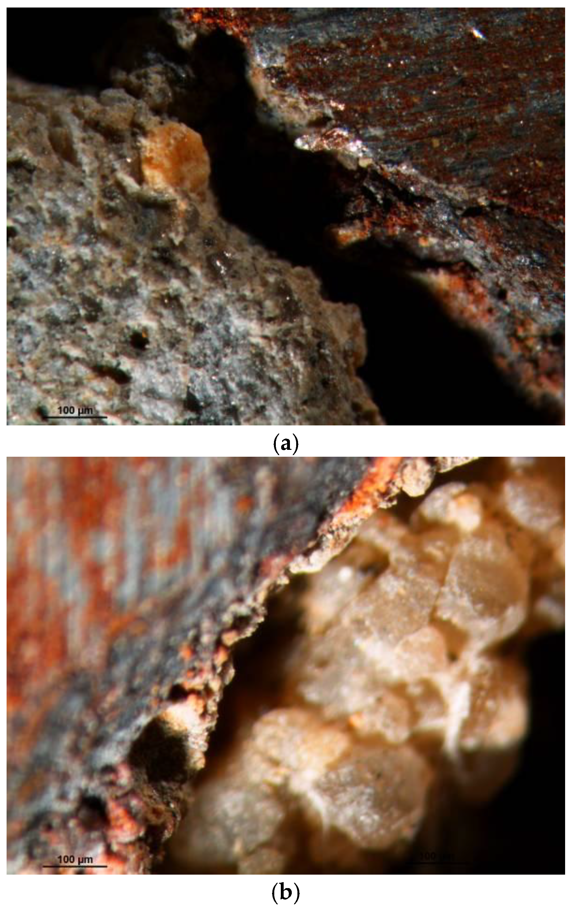
Table 1.
Identification of collected samples.
| Sample | Description | Frontal image | Posterior image |
|---|---|---|---|
| FPo-2 | Zone with apparent intervention (Western facade) |
 |
 |
| FPo-8 | Mask (Western facade) |
 |
 |
| FPo-10 | Geometric ornament FPo-10a (left) and FPo-10b (right) (Western facade) |
 |
 |
| FPri-A1P1 | Frieze FPri-A1P1a (top) and FPri-A1P1b (bottom) (Northern facade) |
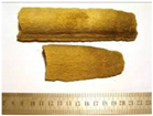 |
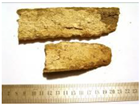 |
| FPri-PB | Frieze (Northern facade) |
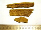 |
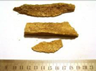 |
| FN-V2P1 | Flower ornament from Balcony on 1st floor. (Eastern facade) |
 |
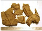 |
Table 2.
Approximate binder:aggregate ratio of mortars.
| Mortar | Binder (weight %) | Aggregate (weight %) | Ratio B:A (w : w) |
|---|---|---|---|
| FPo-2 | 47.5 | 52.5 | 1 : 1 |
| FPo-8 | 28.3 | 71.7 | 3 : 7 |
| FPo-10a | 36.9 | 63.1 | 2 : 3 |
| FPo-10b | 31.6 | 68.4 | 3 : 7 |
| FPri-A1P1a | 30.0 | 70.0 | 3 : 7 |
| FPri-A1P1b | 30.0 | 70.0 | 3 : 7 |
| FPri-PB | 40.4 | 59.6 | 2 : 3 |
| FN-V2P1 | 36.6 | 63.4 | 2 : 3 |
Disclaimer/Publisher’s Note: The statements, opinions and data contained in all publications are solely those of the individual author(s) and contributor(s) and not of MDPI and/or the editor(s). MDPI and/or the editor(s) disclaim responsibility for any injury to people or property resulting from any ideas, methods, instructions or products referred to in the content. |
© 2026 by the authors. Licensee MDPI, Basel, Switzerland. This article is an open access article distributed under the terms and conditions of the Creative Commons Attribution (CC BY) license (http://creativecommons.org/licenses/by/4.0/).
Copyright: This open access article is published under a Creative Commons CC BY 4.0 license, which permit the free download, distribution, and reuse, provided that the author and preprint are cited in any reuse.