
Submitted:
30 January 2026
Posted:
03 February 2026
You are already at the latest version
Abstract
In the field of parallel robots, traditional rigid joints compromise motion accuracy owing to inherent friction and backlash, thus driving the demand for high-performance com-pliant joints. This paper proposes a parametric design method for a two-axis compliant joint that employs flexure leaf springs (FLSs) as rigid joint alternatives. The joint con-figuration consists of four FLSs arranged in a revolute-revolute (RR) layout. Based on Euler–Bernoulli beam theory and the deformation superposition principle, linear ana-lytical models for the compliance and stress characteristics of both the flexure leaf spring (FLS) and the compliant joint are derived. These models are validated through finite element analysis (FEA) and rotational motion experiments. The results indicate that the relative errors between the analytical model (AM) and finite element model (FEM) are below 8%, while the relative errors between the AM and experimental data are within 12%. The proposed parametric design method enables rapid preliminary design and performance evaluation of compliant joints, which highlights its potential for practical engineering application.
Keywords:
compliant joint
; flexure leaf spring
; analytical model
; compliance matrix
1. Introduction
In the field of parallel robots, traditional rigid joints commonly suffer friction and backlash problems during force and motion transmission because they rely on relative rotation against supporting structures. The inevitable gaps between components require regular lubrication, which shortens joint service life and raises long-term maintenance costs. Persistent friction and wear also degrade hinge performance over time and reduce transmission accuracy, a critical concern for high-precision robotics. To address these limitations, compliant mechanisms with flexure hinges have seen extensive development in recent years [1]. These mechanisms produce partial or complete motion through controlled elastic deformation of flexible units. Compared with rigid joints, compliant mechanisms offer integrated structural designs and adjustable stiffness, which minimize friction, eliminate mechanical clearances, and reduce component wear while removing the need for routine lubrication and complex assembly [2,3,4]. Because of these advantages, compliant mechanisms are now widely used in high-precision devices such as sensor systems [5,6], optical component positioning mechanisms [7,8], robotic grippers [9,10], precise positioning stages [11,12], and piezoelectric actuators [13,14].
As a fundamental elastic unit of compliant joints, the FLS [15,16] reproduces the functions of rigid kinematic pairs when arranged in specific configurations. Examples include the double-flexure leaf spring [17] for translational motion, the cross-flexure leaf spring [18,19,20] for rotational motion, the two-axis flexure hinge [21] for a universal hinge, and the compliant spherical (CS) hinge [22] for spherical motion, as illustrated in Figure 1. Fillets are commonly added at FLS ends to reduce stress concentrations and improve fatigue life. The fillet geometry strongly influences hinge performance metrics, including compliance, motion accuracy, and stress distribution [23]. Compliance quantifies the relationship between applied load and deformation. Motion accuracy measures deviations of the motion center, Stress levels define the FLS safe operating load range and provide the basis for estimating fatigue life [24].
Notched flexure hinges, which are hinges composed of the FLSs, have been a central research focus for decades. In 1965, Paros and Weisbord [25] derived stiffness formulas for circular-arc flexure hinges and obtained accurate solutions for multi-directional flexibility, thereby establishing a theoretical foundation for subsequent work. Building on this, Wu et al. [26] developed compliance equations for rectangular single-axis hinges, which simplify analysis and design of compliant mechanisms in engineering practice. Lobontiu et al. [27] later derived closed-form compliance expressions for parabolic and hyperbolic flexure hinges and analyzed their motion accuracy and stress behavior. More recently, Chen et al. [28] introduced a novel single-axis geometry, the Right-Circular Corner-Filleted (RCCF) flexure hinge, which integrates features of a right-circular hinge and a corner-filleted hinge. For optimization, Tian et al. [29] derived dimensionless empirical relations for filleted V-shaped, cycloidal, and circular flexure hinges, employing adaptive Simpson integration and polynomial approximation to improve the accuracy and efficiency of compliance estimates. More recently, Li et al. [30] proposed a power-function–shaped flexure hinge, obtained closed-form compliance expressions via the unit-load method, and examined its motion accuracy to validate the structural benefits of the design.
Beyond single-axis flexure hinges, several studies have established design equations for two-axis flexure hinges, expanding the theoretical basis for multi-axis compliant transmission structures. Lobontiu et al. [31] derived closed-form compliance equations for two-axis hinges with two nonidentical parabolic profiles, providing a precise tool for evaluating asymmetric designs. Wei et al. [32] designed and analyzed a two-axis hinge with a variable elliptical transverse cross-section, and proposed a general formulation that incorporates the axially symmetric circular cross-section hinge as a special case. Li et al. [33] proposed a broadly applicable two-axis elliptical-arc-filleted hinge formed by two distinct elliptical-arc-filleted cutouts and derived analytical compliance expressions for each half-segment, thus establishing a comprehensive theoretical basis for performance analysis and engineering application.
This study presents a systematic structural design and theoretical analysis of a two-axis compliant joint for parallel robots. FLSs with adjustable geometric parameters serve as the primary elastic units. A series–parallel hybrid arrangement realizes the two-axis compliant joint and enables rapid parametric design. Analytical models for the compliance and stress of straight-beam filleted FLSs, and for the two-axis compliant joint, are developed. Model accuracy is validated by comparison with finite element analysis and experimental results. The proposed design method supports preliminary performance prediction during the joint design stage of parallel robots.
This paper is organized as follows: Section 2 describes the design of the FLSs-based two-axis compliant joint, specifies its RR configuration with four FLSs, and defines the key geometric parameters. Section 3 develops linear analytical models for the joint: it derives the compliance model of a single FLS and then extends that model to obtain the overall compliance and stress equations. Section 4 validates the analytical models using FEA for both the single FLS and the compliant joint. Section 5 presents a parametric analysis that evaluates the FLS and the compliant joint performance and examines how structural parameters affect compliance and the maximum allowable deformation. Section 6 offers a practical application case study of the designed compliant joint to demonstrate its engineering feasibility.
2. Design of the Two-Axis Compliant Joint
This section describes a two-axis compliant joint designed for parallel robots to replace conventional Hooker hinges. The joint uses four identical FLSs as elastic units arranged in an RR configuration. It allows rotation about two orthogonal axes, X and Y, and the intersection of those axes defines the joint’s virtual rotation center.
To achieve two-axis rotation, the compliant joint must be flexible along the intended motion axes while remaining stiff in the orthogonal directions. Accordingly, FLSs serve as the primary elastic units in the spatial compliant joint. An integrated two-axis joint is produced by machining slots into a cylindrical metal workpiece with wire electrical discharge machining, which forms series and parallel networks of FLSs. The machined edge profiles function as mechanical stops that limit joint rotation and ensure a safe maximum rotation angle. The joint’s upper and lower bases incorporate positioning stop notches and assembly holes and act as movable interfaces to the drive outriggers, the moving platform, and the fixed platform of the parallel robot.
Define the coordinate system at the virtual rotation center of the compliant joint. Two FLSs aligned along the -axis are labeled Spring 1 and Spring 2, and two aligned along the -axis are labeled Spring 3 and Spring 4. Springs 1 and 2 form the parallel pair Segment 1, while Springs 3 and 4 form the parallel pair Segment 2. Segment 1 and Segment 2 are arranged orthogonally and connected in series. The two-axis compliant joint configuration is shown in Figure 2. Each FLS has length , width , and thickness .
3. Linear Analytical Model of the Compliant Joint
This section derives the general flexibility equation for the FLS with arc notches and develops corresponding compliance and stress models. Using Euler–Bernoulli beam theory and deformation superposition theory, and incorporating the springs’ spatial geometry, we then derive the general flexibility equation for the two-axis compliant joint.
3.1. Compliance Model of the Flexure Leaf Spring
3.1.1. Definition of the Cross-Section
Before developing a comprehensive compliance model for a two-axis compliant joint, it is essential to first establish a numerical model of the joint's fundamental elastic element and analyze its stiffness properties to inform the joint's stiffness design. In precision compliant mechanisms, curved notches, including circular, elliptical, and arc-shaped profiles, are commonly utilized due to their advantageous mechanical behavior. However, addressing every potential FLS geometry and the corresponding design equations at the outset significantly complicates the design process and extends the development cycle. Experimental findings demonstrate that, for equal leaf-spring length and width, right-circular notches provide the highest motion precision, elliptical notches offer superior stress distribution and thus longer fatigue life, while circular-arc notches present a viable compromise between motion accuracy and stress performance [34]. Consequently, this paper selects the elliptical curve from the conic sections as the geometric foundation for arc-shaped notch contours and conducts parametric modeling of the resulting FLS.
The basic elastic unit of the compliant joint is a straight-beam fillet-FLS, comprising a central straight segment and two curved end segments, as shown in Figure 3a. The coordinate origin is located at the fixed end of the FLS; the -axis follows the longitudinal direction, the -axis follows the thickness, and the -axis follows the width. The FLS is partitioned into three segments: Segments 1 and 3 are curved elliptical arcs, and Segment 2 is a straight beam. Segment 1 is characterized by semi-major axis , semi-minor axes , and arc length . Segment 3 is characterized by semi-major axis , semi-minor axis , and arc length . Segment 2 has length and thickness . The arc length of each elliptical segment is related to the ellipse eccentric angle [34], as expressed in Equation (1), and denote the maximum eccentric angles and range from 0 to .The total length of the FLS can be expressed as: .
The FLS is partitioned into infinitesimal segments along the -axis by differentiation, as shown in Figure 3b. The infinitesimal segment and its coordinate are given by Equation (2) and Equation (3). The infinitesimal thickness at coordinate is given by Equation (4).
3.1.2. Compliance of the FLS
The compliance equation for the FLS is derived under the following assumptions: 1. The minimum thickness of the FLS is much smaller than the notch length, so the FLS can be modeled as an Euler–Bernoulli beam; 2. Deformations of the FLS in all directions are sufficiently small to permit linear superposition when multiple loads are applied.
Based on these assumptions, the mechanical model of the FLS is established in Figure 4. One end of the FLS is clamped and the other end is free. A local coordinate system is centered at the geometric center of the free end, and the external loads , , , , and are applied at the origin of this local system. Here , and denote bending moments about the , , and -axes, respectively, while , , and denote forces along the , , and -axes, respectively. These loads together form the generalized force acting on the FLS, and the corresponding generalized displacements are . denotes Young’s modulus, is the shear modulus, and is the Poisson ratio. Under the small-deformation assumption, so that material response is approximately linear for small strains, and applying Euler–Bernoulli beam theory [34], the relationship between the generalized displacements and generalized forces at the free end of the FLS can be expressed as:
The compliance matrix of the FLS can be expressed as:
where is the bending angular deflection about the -axis under the action of moment , and the coefficient represents the rotational compliance, given by:
where denotes the moment of inertia of the cross-section about the -axis, which is defined as:
Substituting Equations (2)-(4) and (10) into Equation (9), the expressions for , , and are derived as follows:
where is the bending angular deflection about the -axis under the action of moment , and the coefficient represents the rotational compliance, given by:
where denotes the moment of inertia of the cross-section about the -axis, which is defined as:
Substituting Equations (2)-(4) and (13) into Equation (12), the expressions for , , and are derived as follows:
where is the twisting angular deflection about the -axis under the action of torsion , and the coefficient represents the torsional compliance, given by:
where denotes the torsional inertia moment of the cross-section about the -axis, which is defined as [35]:
Substituting Equations (2)-(4) and (16) into Equation (15), the expressions for , , and are derived as follows:
where is the bending angular deflection about the -axis under the action of moment generated by force , leading to the following expression:
The coefficient represents the rotational compliance about the -axis under the action of force , which can be expressed as:
Substituting Equations (2)-(4),(13) and (18)into Equation (19), the expressions for , , and are derived as follows:
The coefficient represents the combined effect of bending and shear deformations along the -axis induced by force . The deflection caused by this force is expressed as:
where is the bending deflection, and is the shear deflection, they are respectively expressed as follows:
where is the shear modulus, and is the shear factor [36].
Substituting Equations (2)-(4) into Equations (22) and (23), so the coefficient is expressed as:
The expressions for , , and are derived as follows:
where is the bending angular deflection about the -axis under the action of moment generated by force , leading to the following expression:
The coefficient represents the rotational compliance about the -axis under the action of force , which can be expressed as:
Substituting Equations (2)-(4),(10) and (27)into Equation (28), the expressions for , , and are derived as follows:
The coefficient represents the combined effect of bending and shear deformations along the -axis induced by force . The deflection caused by this force is expressed as:
where is the bending deflection, and is the shear deflection, they are respectively expressed as follow:
Substituting Equations (2)-(4) into Equation (31) and (32), so the coefficient is expressed as:
The expressions for , , and are derived as follows:
It can be easily verified that , and , therefore, the coefficient is equal to , and is equal to . Consequently, the compliance matrix is symmetric.
The coefficient represents the translational deformation along the -axis induced by force , and the deflection is expressed as:
Substituting Equations (2)-(4) into Equation (35), so the coefficient is expressed as:
3.1.3. Stress analysis of the FLS
FLSs provide kinematic motion by elastic deformation under load. Those deformations produce internal stresses that can shorten the service life of the springs and their compliant joints, which constrains practical use. Thus, reliable strength assessment—particularly early-stage prediction of stress magnitudes—is essential to improve performance and ensure structural reliability. When an axial force , a tangential force , and a bending moment act on the free end of a FLS, the maximum stress is given by [37]:
where is the stress concentration coefficient under axial loading, and is the stress concentration coefficient under bending. When the fillet of the FLS is symmetric, and can be expressed as:
where is the dimensionless coefficient that depends on the structural size of the elliptical notch: .
In addition, the bending moment , tangential force and axial force have the following relationship with the rotation angle and deflection ,:
Each stiffness coefficient can be expressed as:
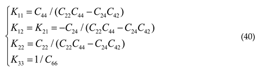
Substituting the Equation (40) into the Equation (37) yields the maximum stress of the FLS under predefined deformation conditions as follows:
3.2. Compliance Model of the Compliant Joint
The two-axis compliant joint serves as the parallel robot’s movable connector; its compliance sets the joint’s rotational range and affects the system dynamics. Thus, modeling and analyzing the joint’s flexibility is essential. Applying the previously described FLS compliance model and deformation superposition theory, we derived the joint compliance matrix.
For the compliant joint, the moving platform and external load application point are defined at the top central position, which is also designated as the origin of the global coordinate system, as illustrated in Figure 5. The four FLS units are denoted as Spring 1, Spring 2, Spring 3, and Spring 4, with a local coordinate system assigned to each unit. The rotation matrix transforming each local coordinate system to the global coordinate system is given by Equation (42):
Where , and are the Euler angles describing the rotation from the local coordinate system to the global coordinate system.
The displacement vector from the local to the global coordinate system is expressed as: .The antisymmetric matrix of the displacement vector is given by:
Therefore, the adjoint matrix of the coordinate transformation can be expressed as:
For two-axis compliant joint, the coordinate transformation of the FLS satisfies the following relation:
The two-axis compliant joint is constructed from four FLS units arranged in a parallel-then-series configuration. Based on the series-parallel combination principle of elastic units, its overall compliance matrix is expressed as:
4. Finite Element Analysis Verification
4.1. Flexure Leaf Spring
To validate the analytical models for the FLSs and compliant joints, nine finite element models (FEMs) of the FLS with varied cross-sectional configurations were developed for verification and comparative analysis. The primary FLS designs comprise straight beam leaf springs and straight beam fillet leaf springs, the latter incorporating chamfers with elliptical notches and circular notches. The different FLS types are shown in Figure 6, and detailed structural parameters appear in Table 1. The FLS material is 17-4PH martensitic precipitation-hardening stainless steel, with a Young’s modulus of 196,000 MPa and a Poisson’s ratio of 0.34. Figure 7 shows one representative FLS finite element model, which uses ten-node hexahedral mesh elements. Boundary conditions fixed all six degrees of freedom at the leaf spring’s fixed end. To evaluate flexibility and stress distribution, three unit forces , and three unit moments were applied at the center of the free end.
Table 2 and Figure 8 present the direct comparison and the relative error between the FEM results and those from the AM. Using the FEM results as reference, the relative error was computed by Equation (47):
Table 2 and Figure 8 show that the relative errors between the AM and the FEM remain within 7.34%. These discrepancies arise from several sources. First, when deriving the FLS rotational stiffness, we simplified the FLS stress–strain model, and the actual deformation is more complex, which introduces modeling error. Second, mesh type and element size in the FEM substantially affect result accuracy and thus produce discretization error. Third, numerical methods themselves converge toward the true solution and therefore retain a residual approximation error. The maximum deviation between AM and FEM thus falls within an acceptable range, supporting the analytical model’s use as an input for the structural design and stiffness calculation of the two-axis compliant joint.
To validate the FLS strength model, distinct force levels and moments were applied to the symmetrically configured FLS 1, FLS 7, and FLS 9 to characterize their von Mises stress distributions. Figure 9 shows the stress fields of these components under maximum load. Table 3 presents a quantitative comparison between FEM results and those from the AM; the relative errors between AM and FEM remained within 5.86%.
4.2. Compliant Joint
Based on the structural types and dimensions of the nine FLSs, finite element models (FEM) of the compliant joints were constructed. The joint axial dimension was determined by the FLS width and the central-hole diameter of the compliant joint, with the relationship (). The joint length was set to 74 mm, based on the design space of the parallel robot. Figure 7 shows one of the compliant joint FEMs, which uses ten-node hexahedral elements. Boundary conditions fixed all six degrees of freedom at the joint’s fixed end. To evaluate flexibility and stress distribution, unit forces and unit moments were applied at the center of the free end. Direct comparisons and relative errors between FEM and the AM of the compliant joints are presented in Table 4 and Figure 10.
Table 4 and Figure 10 show that the relative error between the AM and the FEM for the compliant joint does not exceed 7.63%. This agreement supports the reliability of the compliant joint’s compliance model derived from the FLS model. The residual error primarily arises because the AM includes only the deformable flexible units, while the FEM represents the entire structural prototype and therefore also captures fixed surfaces and the connecting structures between flexible units.
5. Evaluation of the FLS and Compliant Joints with Different Fillets
The dimensions and fillet geometry of the FLS affect its mechanical performance and the behavior of compliant joints by influencing stress concentration, deformation, and fatigue life. This section examines how dimensional variations and fillet designs impact the mechanical behavior of the FLS and the compliant joint, focusing on compliance, von Mises stress distribution, and the optimal configuration for balancing structural flexibility and load-bearing capacity.
5.1. Performance of Compliance
To investigate the effects of FLS structural dimensions (thickness , width , and length ) on its compliance performance, the thickness was set to 1 mm, 2 mm, and 3 mm, with the width ranging from 20 to 40 mm and the length from 10 to 30 mm. For these parameter settings, Figure 11 summarizes how the FLS structural dimensions affect its compliance coefficients.
As illustrated in Figure 11, the effects of the FLS structural dimensions on its compliance coefficients are summarized as follows. Taking the primary compliance direction of as an example, the thickness exerts the strongest influence: with and fixed, the compliance coefficients decrease sharply as increases, indicating a strong negative correlation. Length has a secondary, positive effect: with and fixed, the compliance coefficients increase gradually as increases. Width shows a weak negative correlation: the coefficients fall slightly as increases, but this effect is much smaller than those of and . Thus, the dimensions influence the compliance coefficients in the order .
To examine how fillet dimensions influence the compliance coefficients of the symmetric FLSs, we define the ratio of the semi-minor axis to the semi-major axis of the elliptic curve as , and denote the length of the elliptic arc fillet segment as . Relationships between compliance coefficients and arc fillet structural parameters are derived, as shown in Figure 12.
The compliance coefficient correlates positively with the elliptical semi-major axis . For a fixed , the compliance coefficient increases with , but exhibits a reduced growth rate as it approaches , due to the approaching elastic deformation limit of the flexible structure. In contrast, compliance coefficient shows a negative correlation with , decreasing as the semi-minor axis increases, which is attributed to the enhanced structural stiffness from a fuller elliptical fillet.
5.2. Maximum Deformation
The primary direction compliance of the FLS is a key metric for compliant joint design. To satisfy structural-strength requirements and avoid fatigue, the FLS material’s yield strength limits the maximum allowable deformation. Stress and strain in the FLS depend strongly on its detailed geometry. To isolate the effects of fillet geometry and dimensions on the FLS maximum deformation, all other variables that could influence the outcome were held constant. Specifically, the straight-beam length was fixed at 20 mm, the semi-major axis of the elliptical arc was set to 2 mm, and only the fillet related geometric parameters and were varied. From these models, the maximum stress as a function of the FLS rotation angle in the primary direction was computed. The material selected for this study was 17-4PH martensitic stainless steel with a yield strength of 1180 MPa, and an allowable stress of 580 MPa was adopted to prevent strength failure.
Figure 13 shows the variation of the maximum rotation angle of the FLS under different fillet parameters. The maximum bending deformation increases with and decreases with . At a given , the maximum rotation angle for is significantly larger than for , indicating that a smaller fillet size ratio enhances the spring’s deformability. As approaches , the rate of deformation growth diminishes and sensitivity declines because the structure approaches its elastic deformation limit. These results inform fillet optimization: a smaller favors larger rotation angles, while the effect of get weak at large , requiring a balance between geometric parameters and material strength.
Figure 14 shows the maximum von Mises stress of the FLS across a range of , with the arc segment length fixed at 2 mm () and as the varying parameter; the red dashed line marks the allowable stress was set at 580 MPa. A clear trend appears: for the same , a smaller produces lower stress. The curve for has the steepest slope, which indicates that its stress rises most rapidly as increases, and its absolute stress level is much higher than those for smaller at the same rotation angle. These results indicate that reducing both lowers the overall stress magnitude and reduces the rate at which stress grows with rotation angle—effects that are important for keeping the spring within the 580 MPa allowable limit in design.
6. Case Study
To validate the AM for the two-axis compliant joint introduced above, we fabricated a structural prototype of the joint using the FLS with right-circular fillets. We then assembled a rotational compliance test system for the prototype.
6.1. Prototype Fabrication
A two-axis compliant joint was manufactured in accordance with the structural design method described earlier, using the structural parameters listed in Table 5. The material selected for the prototype was 17-4PH martensitic stainless steel, with a Young’s modulus of 196,000 MPa and a Poisson’s ratio of 0.34.
6.2. Test System
To investigate the bending performance of each principal bending axis of the compliant joint under different loads, we established a rotational compliance test system for the compliant joint. This test system mainly consists of a compliant joint prototype, an optical platform, an autocollimator, a reflector, and several other supporting devices, as illustrated in the Figure 15.
The fixed end of the compliant joint was clamped to the optical platform, and the loading plate was attached to the free end. Gravitational loads were applied along the Z-axis using weights of unit mass 100 g, which produced torque via the loading-plate moment arm; the weights ranged from 100 g to 1000 g. At each increment, the autocollimator measured the angular displacement of the reflector mounted on the compliant joint. From those measurements, we determined the rotation angles about the X/Y/Z-axes under each load and derived the flexibility coefficients for the corresponding rotation axes. All equipment sat on an air-floating isolation platform to suppress external vibrations, and each test was repeated three times.
6.2. Test Results
Figure 16 compares AM predictions with experimental measurements about the X/Y/Z-axes. The results of the AM and the structural prototype are basically consistent.
For the two-axis compliant joint, the average relative error (ARE) of the rotation about the X-axis is 11.04% with a maximum standard deviation (Max Std) of 1.6825×10⁻⁵ rad; the ARE about the Y-axis is 7.20% with a Max Std of 1.1689×10⁻⁵ rad; and the ARE about the Z-axis is 11.93% with a Max Std of 1.2278×10⁻⁵ rad. These discrepancies arise mainly because the AM is simplified and includes only the compliance of the FLS structure, whereas the experimental prototype is a complete physical assembly that also deforms at connecting parts. Measurement uncertainty and machining tolerances of the components further affect the experimental results.
7. Conclusions
This study proposes a parametric design method for a two-axis compliant joint based on FLS, enabling accurate prediction and optimization of joint performance at the initial design stage. The main contributions of this work are summarized as follows:
(1) A parametric model of the straight-beam filleted FLS with chamfers is established, providing a numerical model foundation for the parametric design of the two-axis compliant joint;
(2) Based on the structural characteristics of FLSs, a two-axis compliant joint combining series and parallel configurations is designed, which can achieve structural functions similar to those of a Hooke's hinge. The compliance matrix of the joint is derived using the structural matrix method and the principle of series-parallel connection of springs;
(3) Nine different types of FLSs and corresponding two-axis compliant joints are designed to evaluate the compliance and stress conditions of different structural types. The FEM is employed to verify the accuracy of the proposed model, and the maximum relative errors between the calculation results of the numerical models and the FEM models for the FLS and the compliant joint are 7.34% and 7.63%, respectively;
(4) The effects of structural features of FLSs, such as structural dimensions and fillet shapes, on compliance characteristics and stress conditions are investigated in depth;
(5) A test system is built for the bending characteristics of the two-axis compliant joint, and the analytical model is verified. The test results show that the average relative error of the rotation angle is within 11.93%.
The findings of this study demonstrate that the parametric design method for compliant joints can be effectively applied to the rapid prediction and optimization of the bending performance of two-axis compliant joints. This work provides design insights and technical support for the development of compliant joints in parallel robots.
Author Contributions
Conceptualization, K.F. and H.H.; methodology, K.F.; software, K.F.; validation, J.L.; formal analysis, K.F.; investigation, Z.K. and Z.X.; resources, H.H.; data curation, K.F.; writing—original draft preparation, K.F.; writing—review and editing, H.H.; visualization, K.F.; supervision, C.C. and H.H.; project administration, H.H.; funding acquisition, Z.X. All authors have read and agreed to the published version of the manuscript.
Funding
This research was funded by the National Natural Science Foundation of China [Grant No. 52575078 and 62235018], the National Key Research and Development Program of China [Grant No. 2023YFC2206002], and the Open Foundation of State Key Laboratory Advanced Manufacturing for Optical Systems, CAS [Grant No. KLMSKF20240X].
Data Availability Statement
The datasets generated and supporting the findings of this article are obtainable from the corresponding author upon reasonable request.
Acknowledgments
The authors would like to thank Jinxin Hu, Yongzhi Chu, and others of SREC Department for their help in this research, and express sincere appreciation to the reviewers of this paper for their helpful comments.
Conflicts of Interest
No conflicts of interest exist in the submission of this manuscript, and the manuscript is approved by all authors for publication.
Abbreviations
The following abbreviations are used in this manuscript:
| FLS | Flexure Leaf Spring |
| RR | Revolute-Revolute |
| FEA | Finite Element Analysis |
| AM | Analytical Model |
| FEM | Finite Element Model |
References
- Ling, M.; Howell, L.L.; Cao, J.; Chen, G. Kinetostatic and Dynamic Modeling of Flexure-Based Compliant Mechanisms: A Survey. Applied Mechanics Reviews 2020, 72, 030802. [Google Scholar] [CrossRef]
- Du, S.; Liu, J.; Bu, H.; Zhang, L. A Novel Design of a High-Performance Flexure Hinge with Reverse Parallel Connection Multiple-Cross-Springs. Review of Scientific Instruments 2020, 91, 035121. [Google Scholar] [CrossRef] [PubMed]
- Wang, X.; Yu, Y.; Xu, Z.; Xu, A.; Qin, C. Modelling and Performance Analysis of a Curvature-Adjustable Multiple-Axis Flexure Hinge Based on Bézier Curve. Proceedings of the Institution of Mechanical Engineers, Part C: Journal of Mechanical Engineering Science 2024, 238, 3710–3723. [Google Scholar] [CrossRef]
- Wei, H.; Yang, J.; Wu, F.; Niu, X.; Shirinzadeh, B. Analytical Modelling and Experiments for Hybrid Multiaxis Flexure Hinges. Precision Engineering 2022, 76, 294–304. [Google Scholar] [CrossRef]
- Chen, W.; Kang, S.; Lu, Q.; Zhang, Q.; Wei, H.; Zhang, Y.; Lin, Z.; Luo, L. A Novel Bridge-Type Compliant Displacement Amplification Mechanism under Compound Loads Based on the Topology Optimisation of Flexure Hinge and Its Application in Micro-Force Sensing. Smart Mater. Struct. 2024, 33, 015020. [Google Scholar] [CrossRef]
- Wang, F.; Jiang, Q.; Zhang, Y.; Ibrahim, R.; Li, D. A Miniature Triaxial Force Sensor Based on Fiber Bragg Gratings for Flexible Endoscopic Robot. Measurement 2024, 232, 114645. [Google Scholar] [CrossRef]
- Liu, R.; Li, Z.; Yang, X.; Li, Q.; Yong, Q. Design of Biaxial Flexural Mount for a Rectangular Mirror with Large Aspect Ratio of a Space Telescope. Mechanics Based Design of Structures and Machines 2023, 51, 3273–3294. [Google Scholar] [CrossRef]
- Aerospace Mechatronics and Control Technology: Selected Contributions from 2021 7th Asia Conference on Mechanical Engineering and Aerospace Engineering; Ding, H., Ed.; Springer Aerospace Technology; Springer Nature Singapore: Singapore, 2022; ISBN 978-981-16-6639-1.
- Tschiersky, M.; De Jong, J.J.; Brouwer, D.M. Flexure Hinge Design and Optimization for Compact Anthropomorphic Grippers Made via Metal Additive Manufacturing. Journal of Mechanical Design 2024, 146, 015001. [Google Scholar] [CrossRef]
- Liu, C.-H.; Yang, S.-Y.; Shih, Y.-C. Optimal Design of a Highly Self-Adaptive Gripper with Multi-Phalange Compliant Fingers for Grasping Irregularly Shaped Objects. IEEE Robot. Autom. Lett. 2023, 8, 7026–7033. [Google Scholar] [CrossRef]
- Zhang, Q.; Dong, W.; Xu, Q.; Goteea, B.J.; Gao, Y. FlexDelta: A Flexure-Based Fully Decoupled Parallel Xyz Positioning Stage with a Long Stroke. Precision Engineering 2024, 88, 707–717. [Google Scholar] [CrossRef]
- Zhang, F.; Huang, Q.; Zhang, C.; Cheng, B.; Cheng, R.; Zhang, L.; Li, H. Design and Experiment of Multidimensional and Subnanometer Stage Driven by Spatially Distributed Piezoelectric Ceramics. Review of Scientific Instruments 2024, 95, 053702. [Google Scholar] [CrossRef] [PubMed]
- Wang, L.; Wang, H.; Jiang, J.; Luo, T. Development of a Novel Piezoelectric Actuator Based on Stick–Slip Principle by Using Asymmetric Constraint. Micromachines 2023, 14, 1140. [Google Scholar] [CrossRef]
- Nguyen, X.-H.; Nguyen, D.-T. A Novel Dynamic Modeling Framework for Flexure Mechanism-Based Piezoelectric Stick–Slip Actuators with Integrated Design Parameter Analysis. Machines 2025, 13, 787. [Google Scholar] [CrossRef]
- Iandiorio, C.; Salvini, P. Elasto-Kinematics and Instantaneous Invariants of Compliant Mechanisms Based on Flexure Hinges. Micromachines 2023, 14, 783. [Google Scholar] [CrossRef]
- Valentini, P.P.; Pennestrì, E. Second-Order Approximation Pseudo-Rigid Model of Leaf Flexure Hinge. Mechanism and Machine Theory 2017, 116, 352–359. [Google Scholar] [CrossRef]
- Bai, R.; Chen, G.; Awtar, S. Closed-Form Solution for Nonlinear Spatial Deflections of Strip Flexures of Large Aspect Ratio Considering Second Order Load-Stiffening. Mechanism and Machine Theory 2021, 161, 104324. [Google Scholar] [CrossRef]
- Iandiorio, C.; Cirelli, M.; Salvini, P.; Valentini, P.P. Elasto-Kinematics and Second-Order Pseudo-Rigid Model of Cross-Axis Flexure Hinges. Mechanism and Machine Theory 2025, 205, 105894. [Google Scholar] [CrossRef]
- Bilancia, P.; Berselli, G.; Magleby, S.; Howell, L. On the Modeling of a Contact-Aided Cross-Axis Flexural Pivot. Mechanism and Machine Theory 2020, 143, 103618. [Google Scholar] [CrossRef]
- Merriam, E.G.; Howell, L.L. Non-Dimensional Approach for Static Balancing of Rotational Flexures. Mechanism and Machine Theory 2015, 84, 90–98. [Google Scholar] [CrossRef]
- Liang, W.; Xie, Z.; Xu, Z.; Liu, L.; Li, J.; Zhong, S. Influence of the Geometric Parameters of Two-Axis Rectangular Flexure Hinges on the Coupling of the Force Sensor. Meas. Sci. Technol. 2025, 36, 045014. [Google Scholar] [CrossRef]
- Trease, B.P.; Moon, Y.; Kota, S. Design of Large-Displacement Compliant Joints. Journal of Mechanical Design 2005, 127, 788–798. [Google Scholar] [CrossRef]
- Ma, W.; Wang, R.; Zhou, X.; Meng, G. The Performance Comparison of Typical Notched Flexure Hinges. Proceedings of the Institution of Mechanical Engineers, Part C: Journal of Mechanical Engineering Science 2020, 234, 1859–1867. [Google Scholar] [CrossRef]
- Wang, H.; Wu, S.; Shao, Z. Analytical Compliance Equations of Generalized Elliptical-Arc-Beam Spherical Flexure Hinges for 3D Elliptical Vibration-Assisted Cutting Mechanisms. Materials 2021, 14, 5928. [Google Scholar] [CrossRef] [PubMed]
- Paros, J.; Weisbord, L. How to Design Flexure Hinges. Mach Des 1965, 37, 151–156. [Google Scholar]
- Wu, Y.; Zhou, Z. Design Calculations for Flexure Hinges. Review of Scientific Instruments 2002, 73, 3101–3106. [Google Scholar] [CrossRef]
- Lobontiu, N.; Paine, J.S.N.; O’Malley, E.; Samuelson, M. Parabolic and Hyperbolic Flexure Hinges: Flexibility, Motion Precision and Stress Characterization Based on Compliance Closed-Form Equations. Precision Engineering 2002, 26, 183–192. [Google Scholar] [CrossRef]
- Chen, G.-M.; Jia, J.-Y.; Li, Z.-W. Right-Circular Corner-Filleted Flexure Hinges. In Proceedings of the IEEE International Conference on Automation Science and Engineering, 2005; IEEE: Edmonton, AB, Canada, 2005; pp. 249–253. [Google Scholar]
- Tian, Y.; Shirinzadeh, B.; Zhang, D.; Zhong, Y. Three Flexure Hinges for Compliant Mechanism Designs Based on Dimensionless Graph Analysis. Precision Engineering 2010, 34, 92–100. [Google Scholar] [CrossRef]
- Li, Q.; Pan, C.; Xu, X. Closed-Form Compliance Equations for Power-Function-Shaped Flexure Hinge Based on Unit-Load Method. Precision Engineering 2013, 37, 135–145. [Google Scholar] [CrossRef]
- Lobontiu, N.; Garcia, E. Two-Axis Flexure Hinges with Axially-Collocated and Symmetric Notches. Computers & Structures 2003, 81, 1329–1341. [Google Scholar] [CrossRef]
- Wei, H.; Tian, Y.; Zhao, Y.; Ling, M.; Shirinzadeh, B. Two-Axis Flexure Hinges with Variable Elliptical Transverse Cross-Sections. Mechanism and Machine Theory 2023, 181, 105183. [Google Scholar] [CrossRef]
- Li, L.; Zhang, D.; Guo, S.; Qu, H. A Generic Compliance Modeling Method for Two-Axis Elliptical-Arc-Filleted Flexure Hinges. Sensors 2017, 17, 2154. [Google Scholar] [CrossRef]
- Chen, G.; Shao, X.; Huang, X. A New Generalized Model for Elliptical Arc Flexure Hinges. Review of Scientific Instruments 2008, 79, 095103. [Google Scholar] [CrossRef]
- Young, W.C.; Budynas, R.G.; Roark, R.J. Roark’s Formulas for Stress and Strain; McGraw-Hill international edition, General engineering series; 7. ed., reprint.; McGraw-Hill: New York, 2011; ISBN 978-0-07-072542-3.
- Chen, G.; Liu, X.; Du, Y. Elliptical-Arc-Fillet Flexure Hinges: Toward a Generalized Model for Commonly Used Flexure Hinges. Journal of Mechanical Design 2011, 133, 081002. [Google Scholar] [CrossRef]
- Wang, J.; Liu, X. Generalized Equations for Estimating Stress Concentration Factors of Various Notch Flexure Hinges. Journal of Mechanical Design 2014, 136, 031009. [Google Scholar] [CrossRef]
Figure 1.
Flexure hinges constructed with FLS units to fulfill diverse functional requirements.
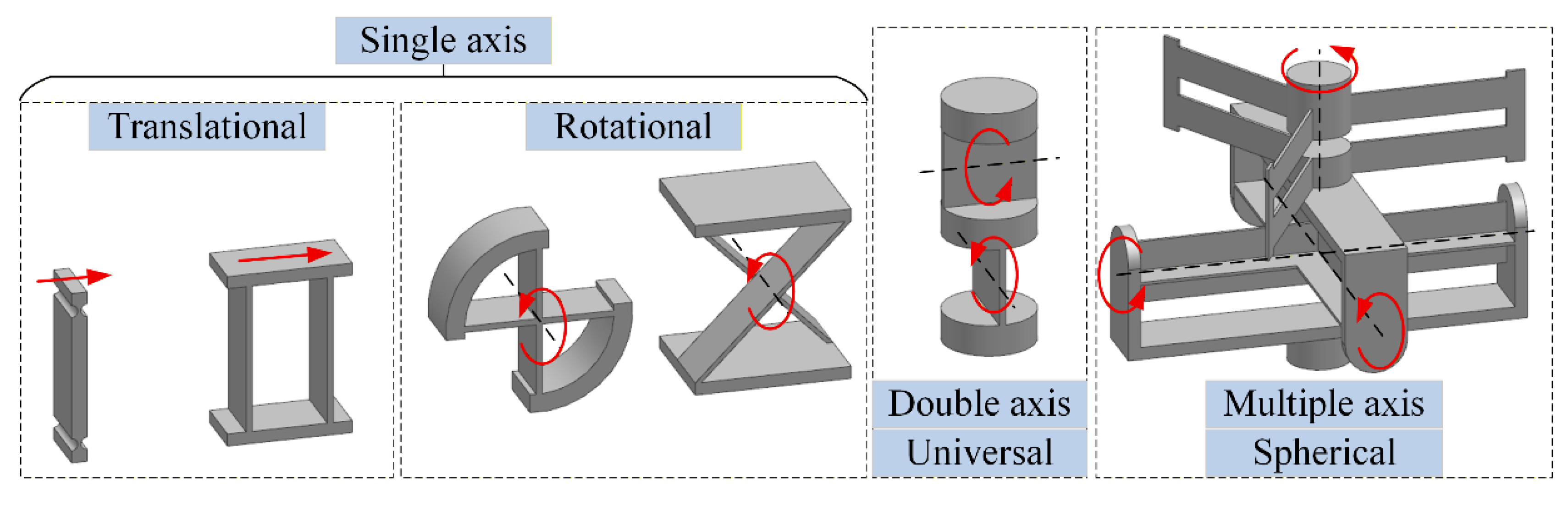
Figure 2.
Compliant joint constructed with the FLS units to fulfill diverse functional requirements.
Figure 2.
Compliant joint constructed with the FLS units to fulfill diverse functional requirements.
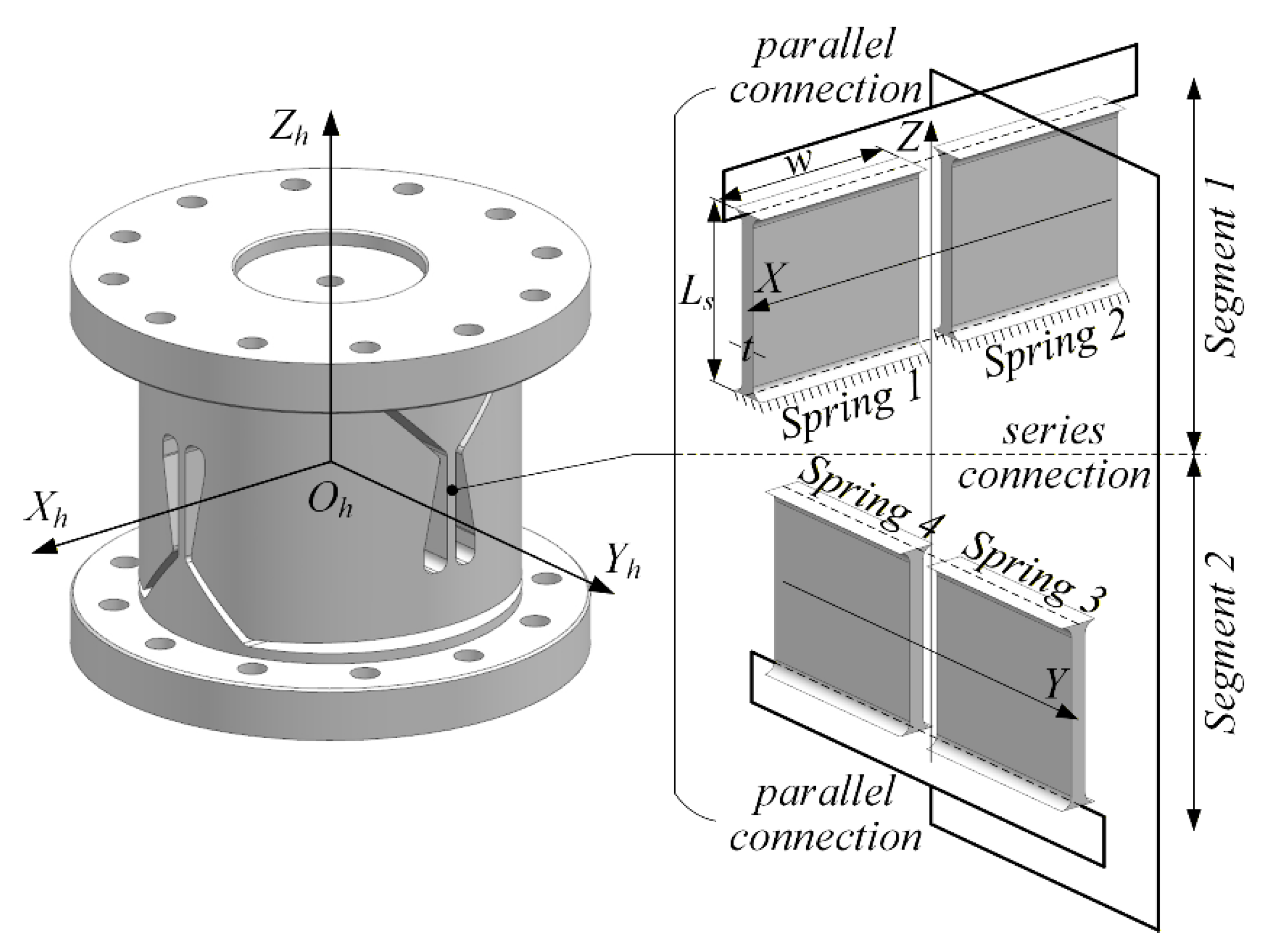
Figure 3.
Analysis of the cross-section profile of the FLS.
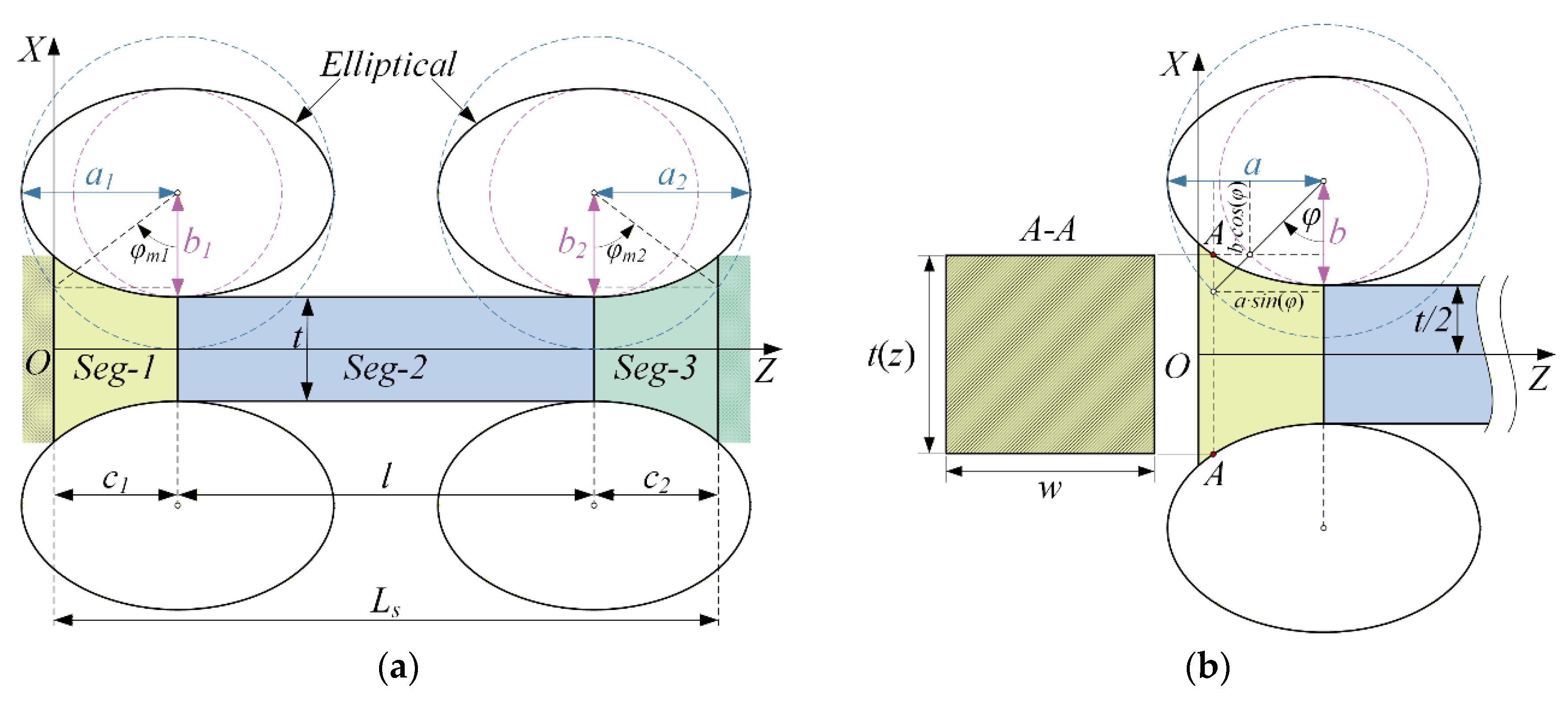
Figure 4.
Schematic diagram of the FLS structure.
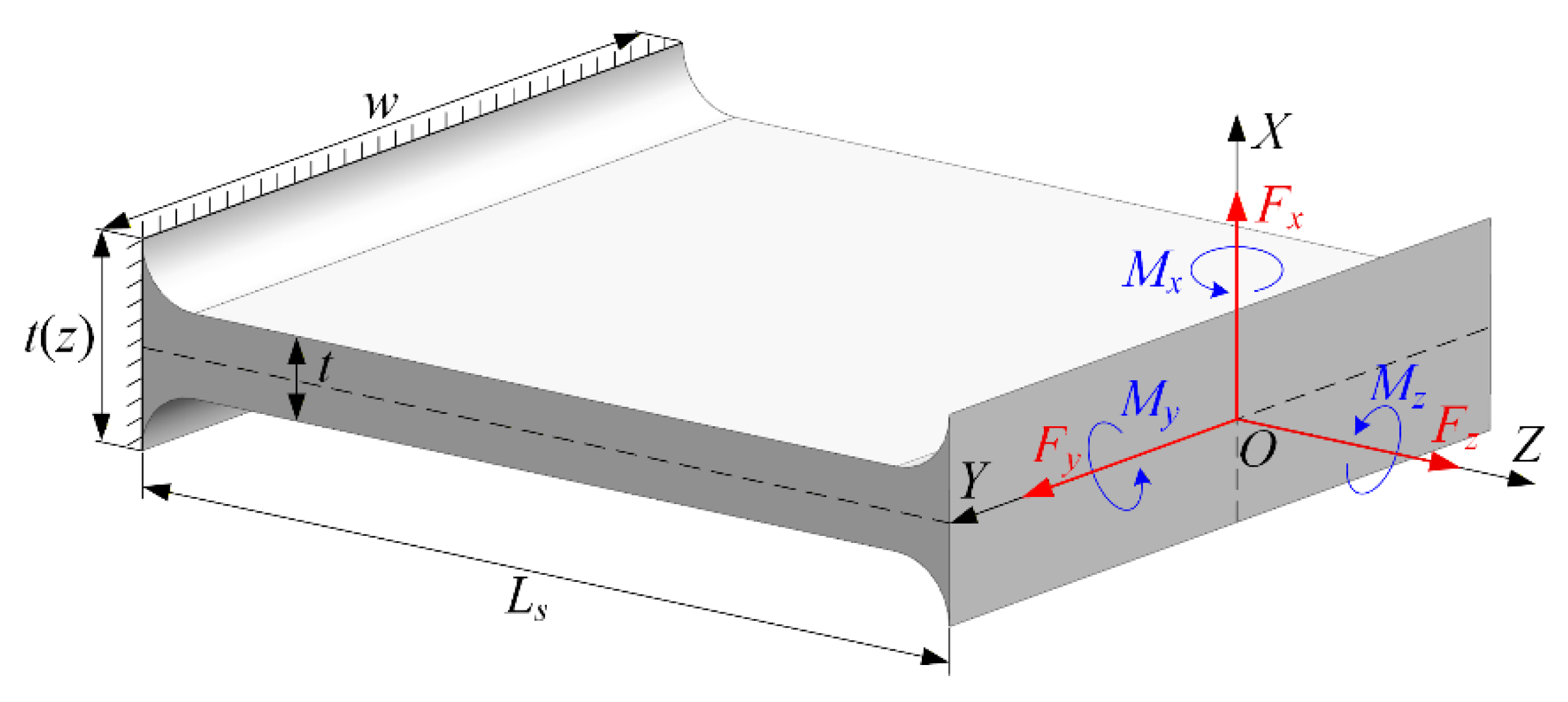
Figure 5.
Coordinate system of the two-axis compliant joint.
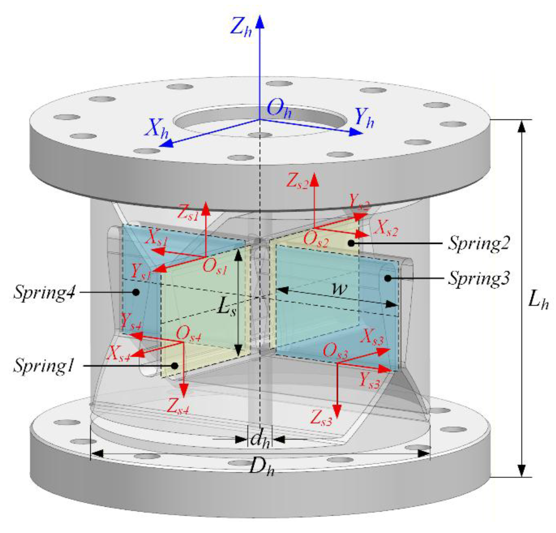
Figure 6.
The FLSs with different fillet geometries.
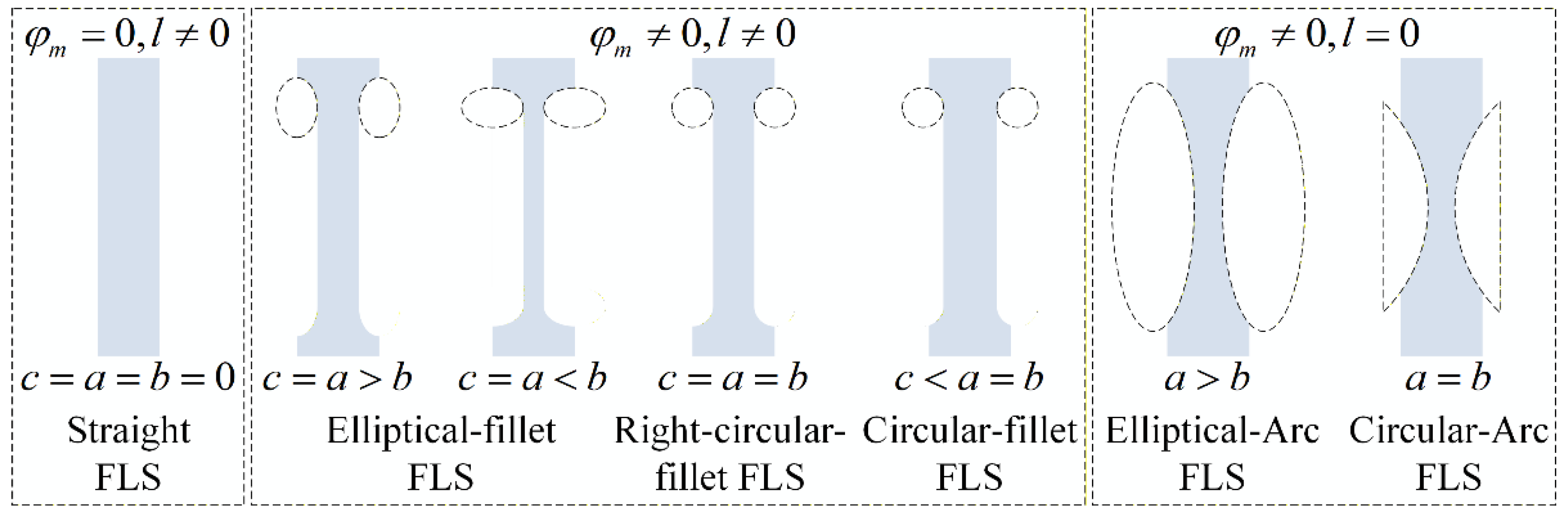
Figure 7.
The FEM of the FLS and compliant joint with elliptical fillet.
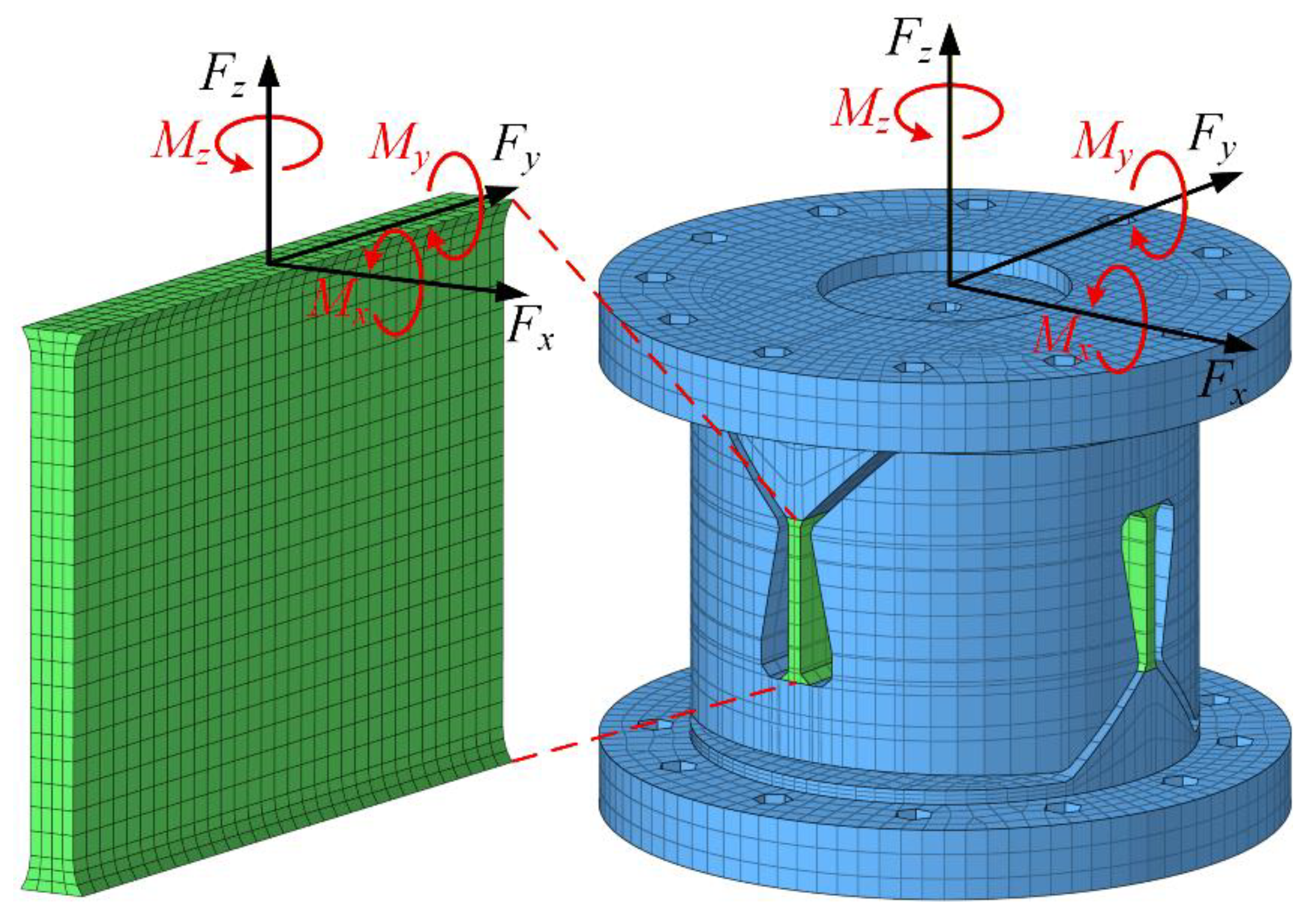
Figure 8.
Compliance and relative error curves of FLSs with different fillet geometries: (a) Compliance curves; (b) Compliance relative error curves.
Figure 8.
Compliance and relative error curves of FLSs with different fillet geometries: (a) Compliance curves; (b) Compliance relative error curves.
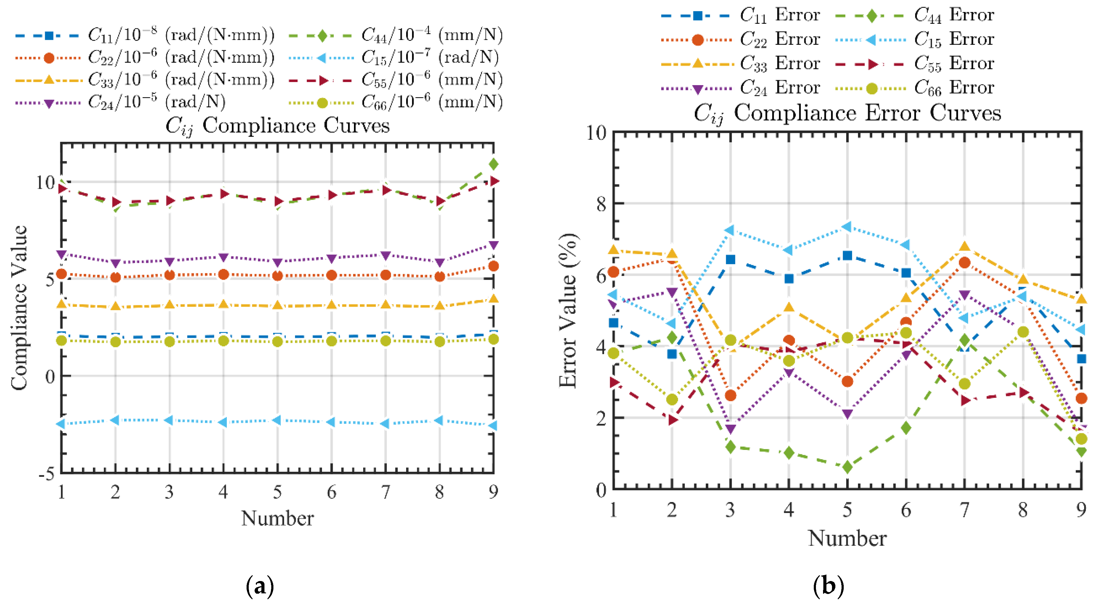
Figure 9.
Stress distributions under maximum load condition: (a) FLS 1; (b) FLS 7; (c) FLS 9.
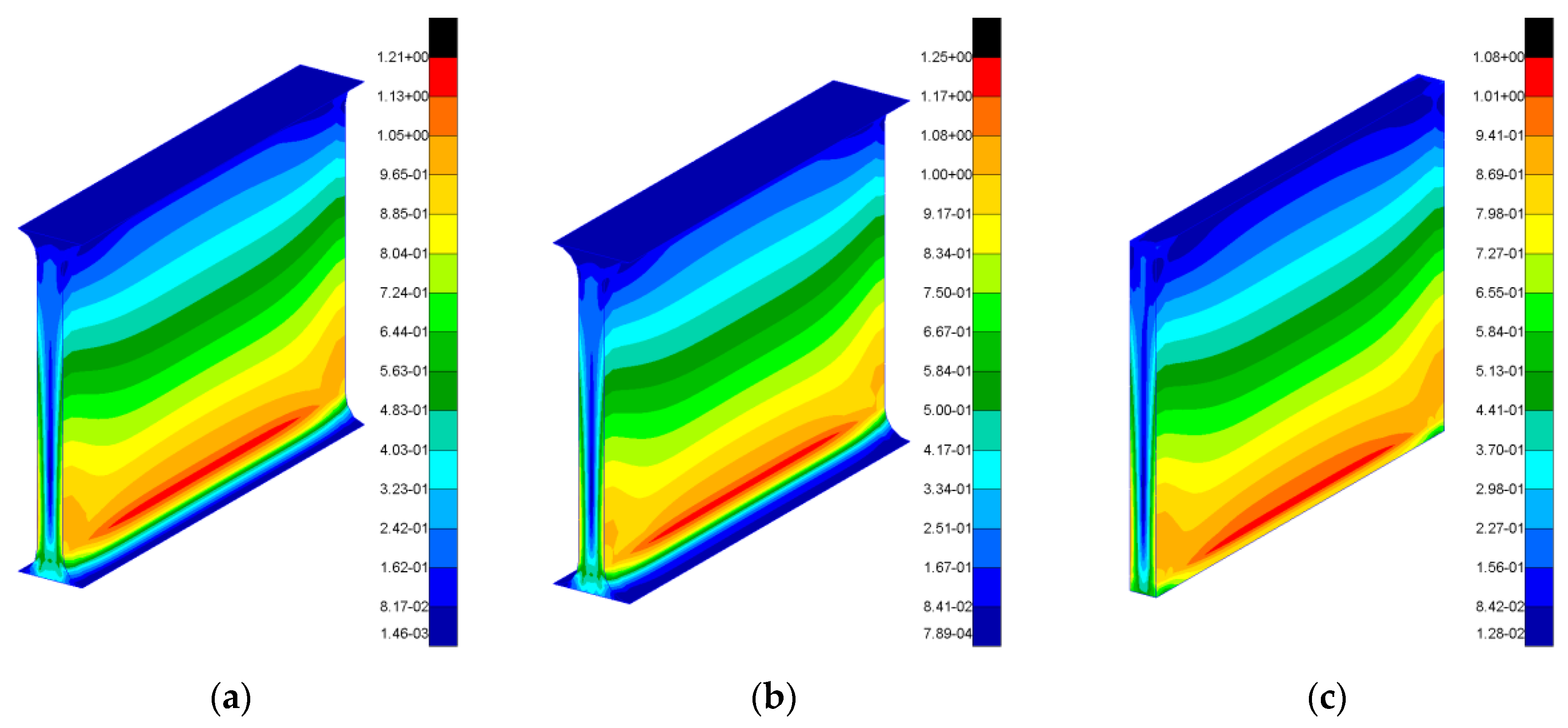
Figure 10.
Compliance coefficients and relative errors of the compliant joints with different fillet geometries: (a) C11; (b) C22; (c) C33; (d) C24; € C44; (f) C55; (g) C66.
Figure 10.
Compliance coefficients and relative errors of the compliant joints with different fillet geometries: (a) C11; (b) C22; (c) C33; (d) C24; € C44; (f) C55; (g) C66.
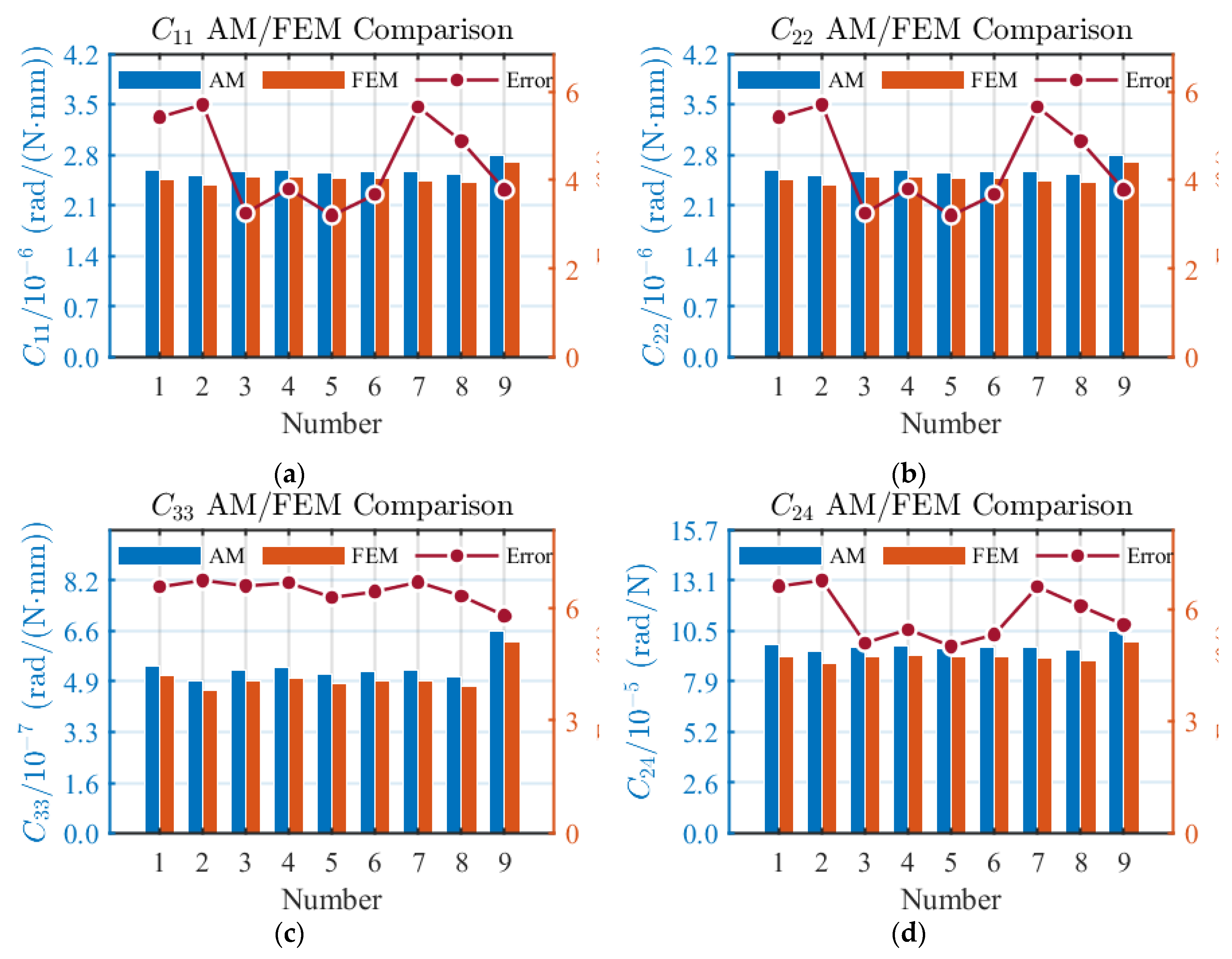
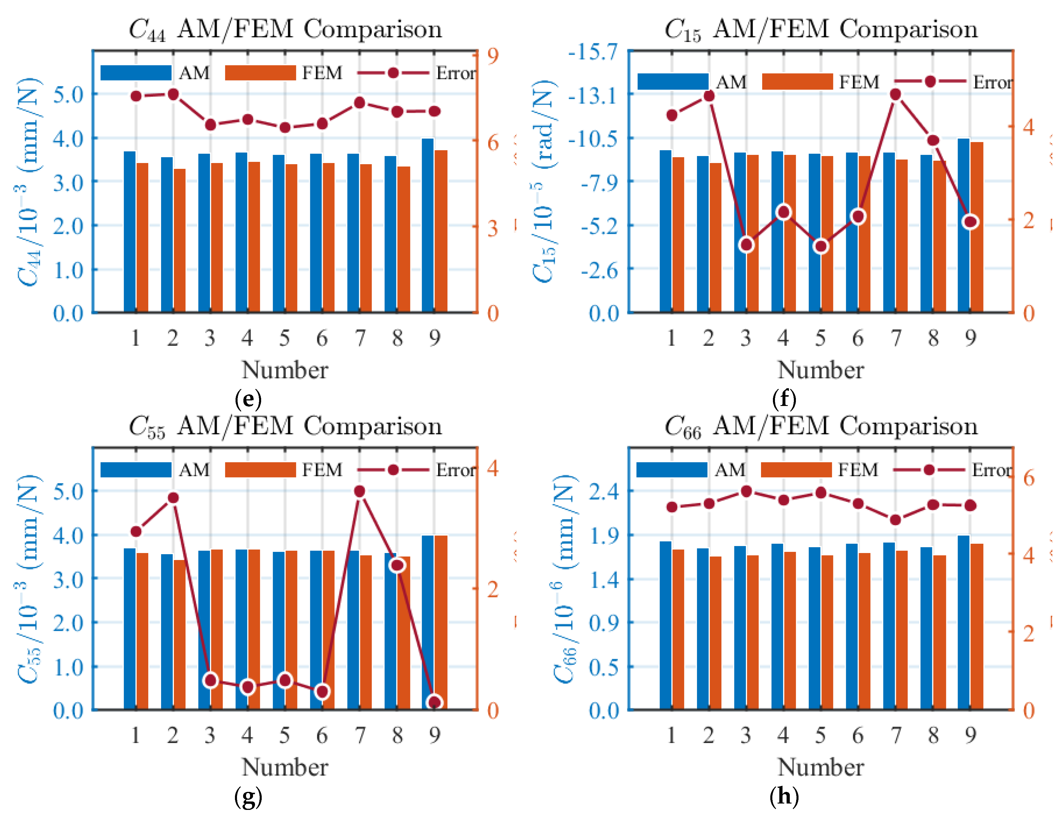
Figure 11.
The influence of t, w and l on compliance of the FLS: (a) C11; (b) C22; (c) C33; (d) C24; (e) C44; (f) C55; (g) C66.
Figure 11.
The influence of t, w and l on compliance of the FLS: (a) C11; (b) C22; (c) C33; (d) C24; (e) C44; (f) C55; (g) C66.
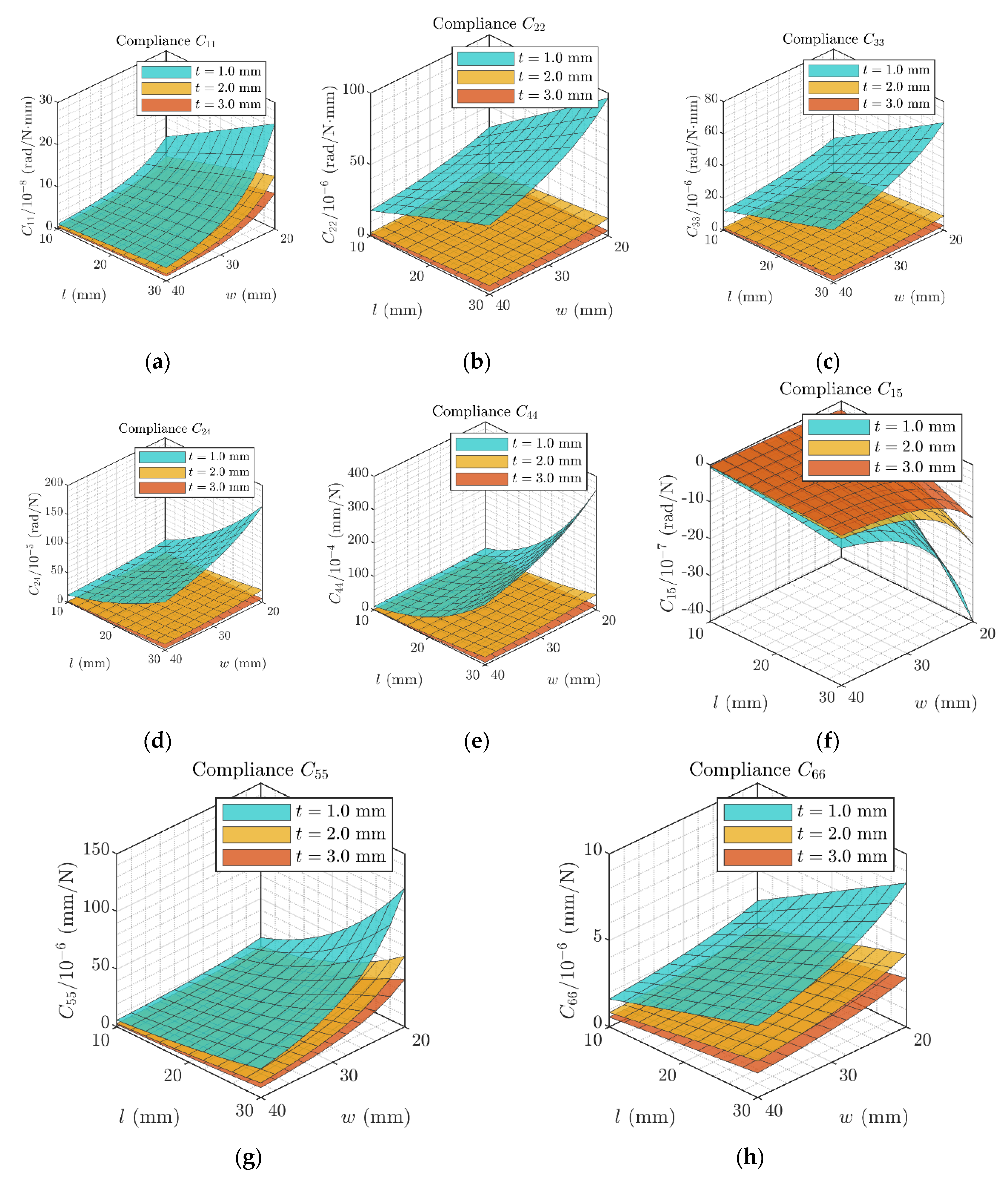
Figure 12.
The influence of φm, λ and a on compliance of the FLS: (a) C11; (b) C22; (c) C33; (d) C24; (e) C44; (f) C55; (g) C66.
Figure 12.
The influence of φm, λ and a on compliance of the FLS: (a) C11; (b) C22; (c) C33; (d) C24; (e) C44; (f) C55; (g) C66.
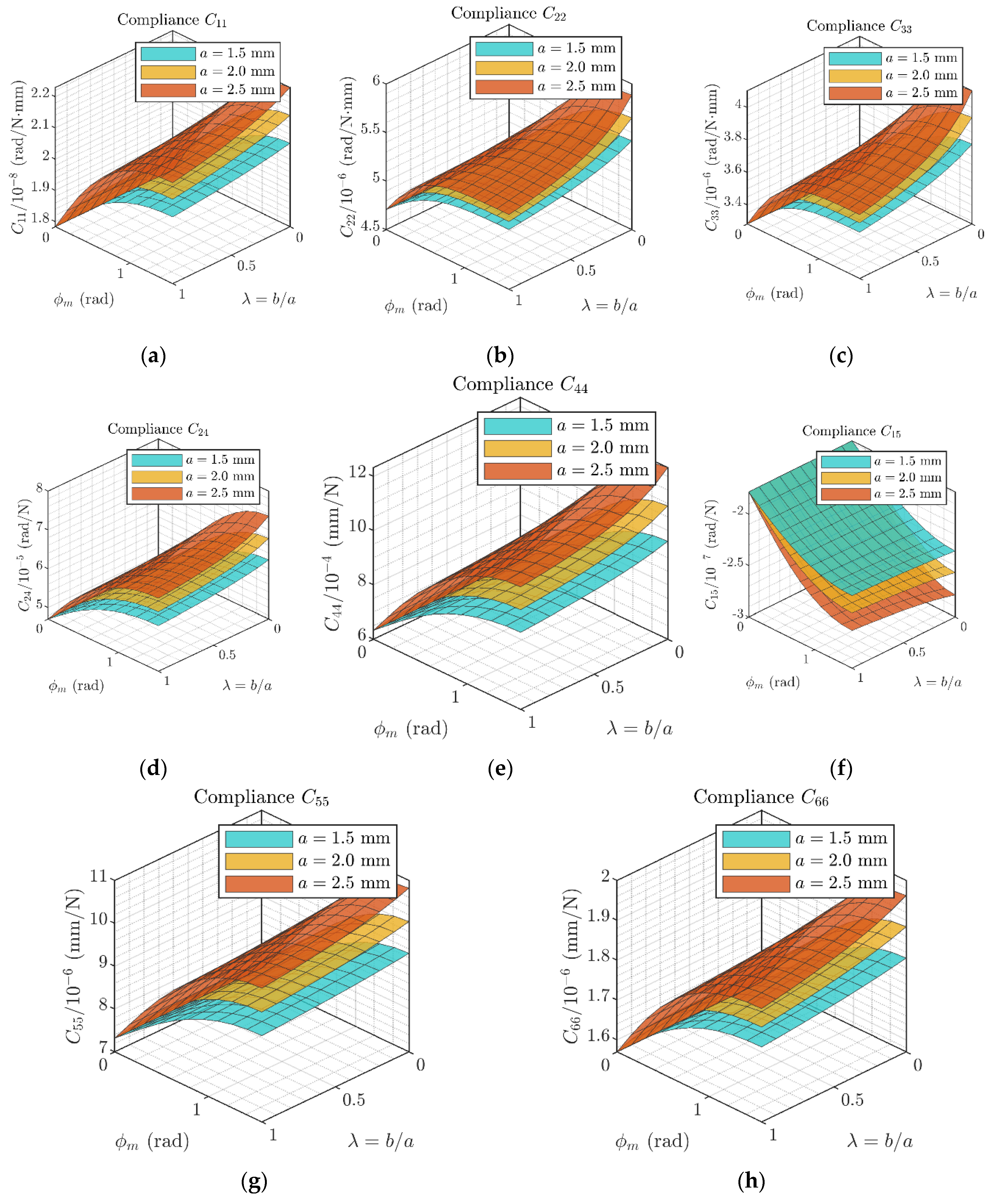
Figure 13.
The maximum rotational angle for the FLS with different fillet geometries.
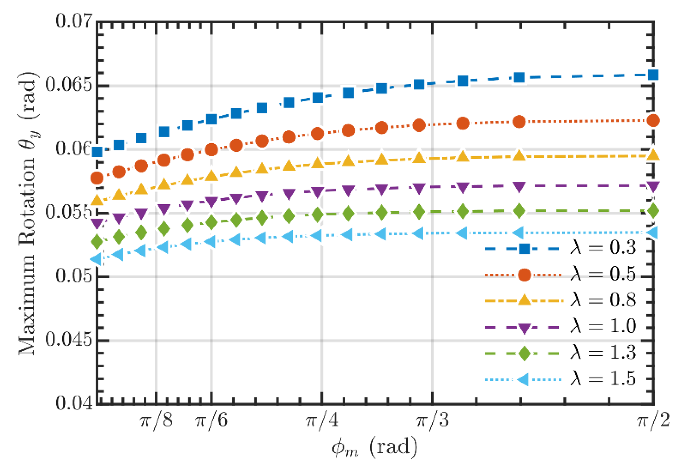
Figure 14.
The maximum von Mises stress of the FLSs under different rotational angles.
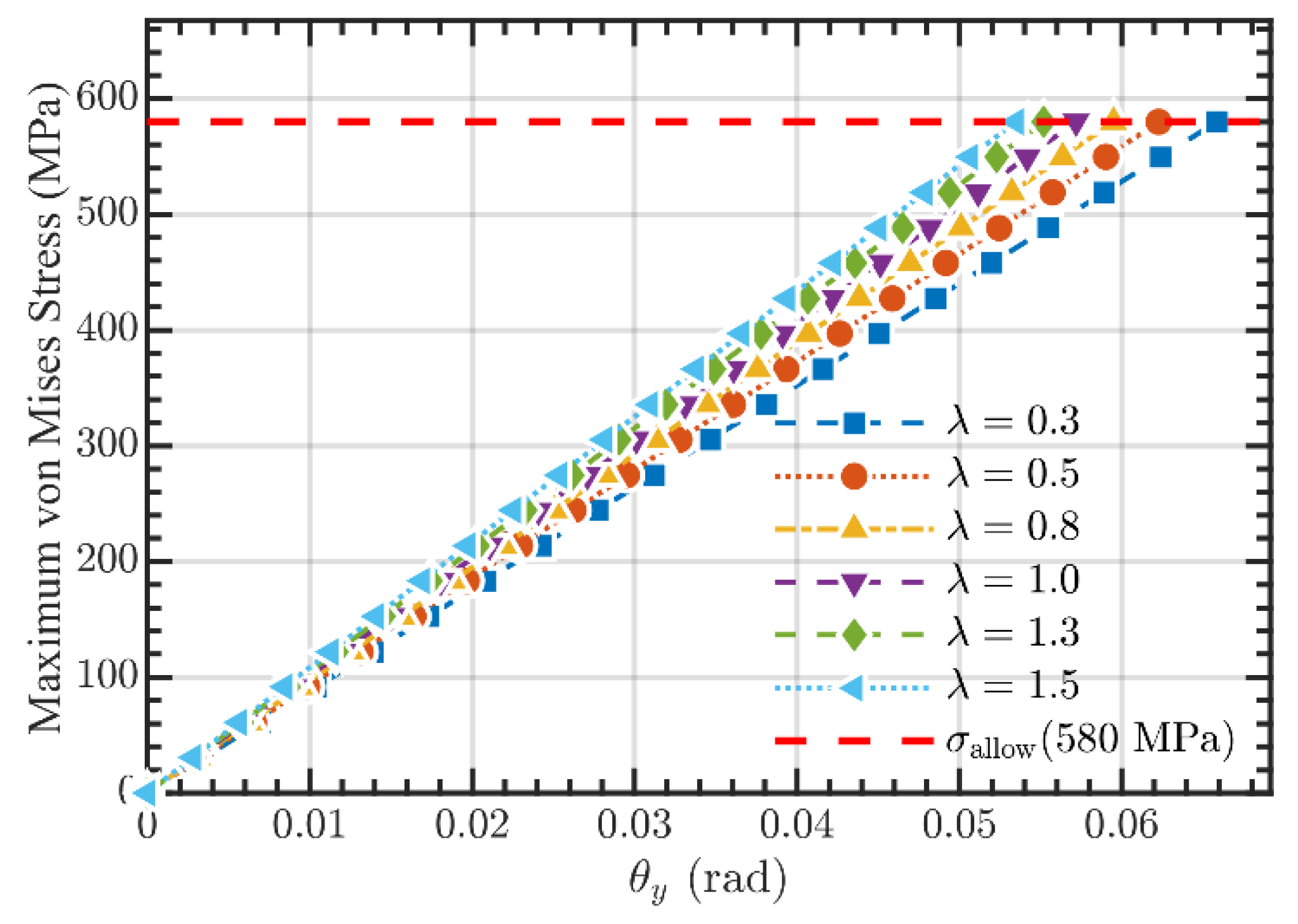
Figure 15.
Compliance test experiment: (a) X/Y-axis test scheme; (b) Z-axis test scheme; (c) X/Y-axis test system; (d) Z-axis test system; (e) Compliant joint prototype.
Figure 15.
Compliance test experiment: (a) X/Y-axis test scheme; (b) Z-axis test scheme; (c) X/Y-axis test system; (d) Z-axis test system; (e) Compliant joint prototype.
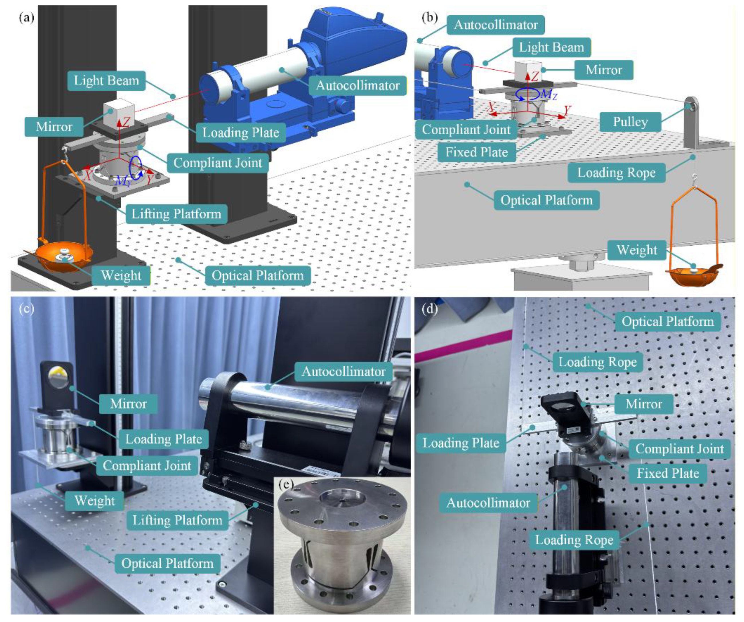
Figure 16.
Comparison between the AM and experimental results of the two-axis compliant joint: (a) X-axis compliance; (b) Y-axis compliance; (c) Z-axis compliance.
Figure 16.
Comparison between the AM and experimental results of the two-axis compliant joint: (a) X-axis compliance; (b) Y-axis compliance; (c) Z-axis compliance.
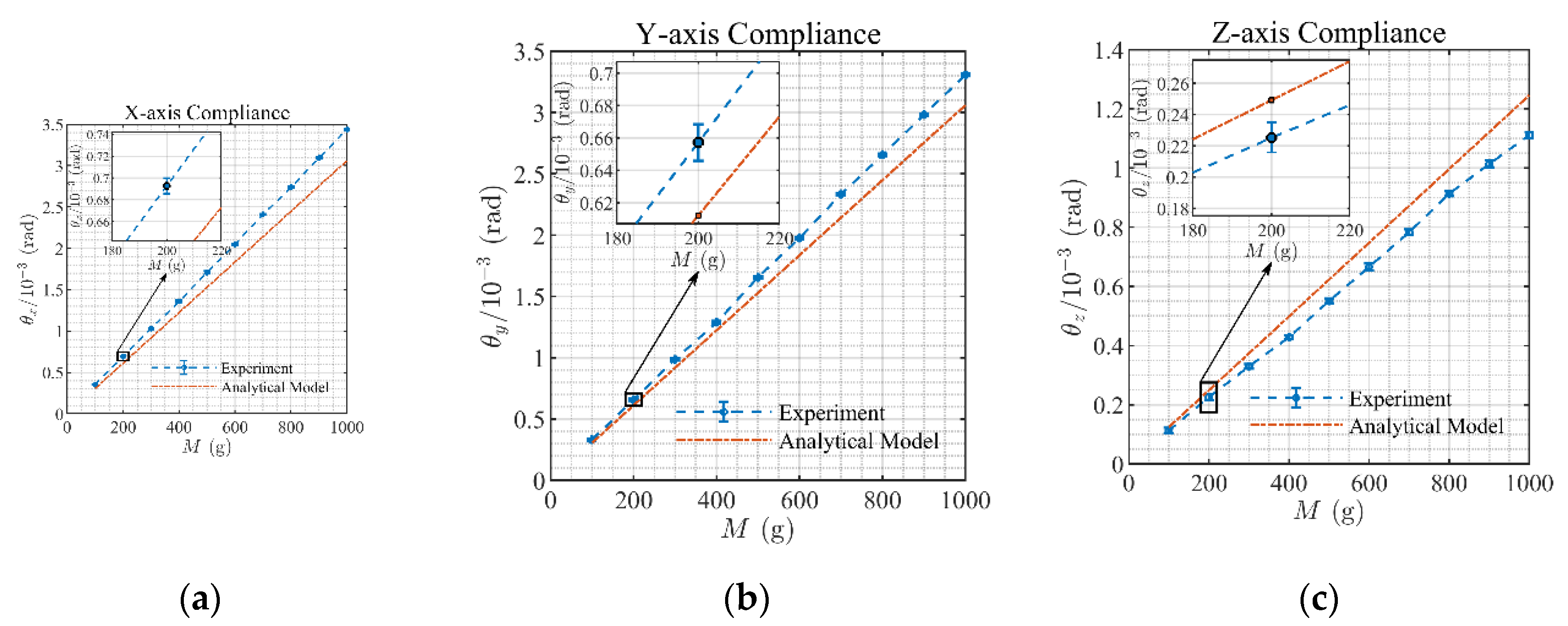

Table 1.
Structure parameters of the FLSs with different fillet geometries.
| No. | Type | |||||
| 1 | Elliptical-Fillet | 90 | 2 | 1.5 | 2 | 24 |
| 2 | Elliptical-Fillet | 90 | 1.5 | 2 | 1.5 | 23 |
| 3 | Elliptical-Arc-Fillet | 45 | 2 | 1.5 | 1.414 | 22.828 |
| 4 | Elliptical-Arc-Fillet | 60 | 2 | 1.5 | 1.732 | 23.464 |
| 5 | Circular-Arc-Fillet | 45 | 2 | 2 | 1.414 | 22.828 |
| 6 | Circular-Arc-Fillet | 60 | 2 | 2 | 1.732 | 23.464 |
| 7 | Right-Circular-Fillet | 90 | 2 | 2 | 2 | 24 |
| 8 | Right-Circular-Fillet | 90 | 1.5 | 1.5 | 1.5 | 23 |
| 9 | Straight | 90 | 2 | 0 | 2 | 24 |
Table 2.
Comparison of compliance between the AM and the FEM for the FLSs.
| No. | Result | ||||||||
| 1 | AM | 2.068 | 5.250 | 3.662 | 6.300 | 9.807 | -2.482 | 9.641 | 1.820 |
| FEM | 2.169 | 4.949 | 3.433 | 5.988 | 9.449 | -2.625 | 9.938 | 1.892 | |
| Error | 4.66% | 6.08% | 6.67% | 5.21% | 3.79% | 5.45% | 2.99% | 3.81% | |
| 2 | AM | 1.986 | 5.075 | 3.539 | 5.836 | 8.738 | -2.284 | 8.955 | 1.748 |
| FEM | 2.064 | 4.767 | 3.321 | 5.53 | 8.382 | -2.395 | 9.132 | 1.793 | |
| Error | 3.78% | 6.46% | 6.56% | 5.53% | 4.25% | 4.63% | 1.94% | 2.51% | |
| 3 | AM | 2.008 | 5.195 | 3.622 | 5.929 | 8.937 | -2.292 | 9.030 | 1.767 |
| FEM | 2.146 | 5.062 | 3.485 | 5.829 | 9.044 | -2.471 | 9.413 | 1.844 | |
| Error | 6.43% | 2.63% | 3.93% | 1.72% | 1.18% | 7.24% | 4.07% | 4.18% | |
| 4 | AM | 2.044 | 5.233 | 3.650 | 6.140 | 9.426 | -2.398 | 9.376 | 1.799 |
| FEM | 2.172 | 5.024 | 3.474 | 5.944 | 9.331 | -2.57 | 9.75 | 1.866 | |
| Error | 5.89% | 4.16% | 5.07% | 3.30% | 1.02% | 6.69% | 3.84% | 3.59% | |
| 5 | AM | 2.001 | 5.158 | 3.597 | 5.888 | 8.847 | -2.284 | 8.993 | 1.761 |
| FEM | 2.141 | 5.007 | 3.455 | 5.765 | 8.902 | -2.465 | 9.390 | 1.839 | |
| Error | 6.54% | 3.02% | 4.11% | 2.13% | 0.62% | 7.34% | 4.23% | 4.24% | |
| 6 | AM | 2.033 | 5.186 | 3.617 | 6.084 | 9.302 | -2.385 | 9.316 | 1.790 |
| FEM | 2.164 | 4.955 | 3.434 | 5.862 | 9.145 | -2.56 | 9.713 | 1.872 | |
| Error | 6.05% | 4.66% | 5.33% | 3.79% | 1.72% | 6.84% | 4.09% | 4.38% | |
| 7 | AM | 2.054 | 5.197 | 3.625 | 6.236 | 9.663 | -2.465 | 9.562 | 1.808 |
| FEM | 2.139 | 4.887 | 3.395 | 5.913 | 9.276 | -2.589 | 9.806 | 1.863 | |
| Error | 3.97% | 6.34% | 6.77% | 5.46% | 4.17% | 4.79% | 2.49% | 2.95% | |
| 8 | AM | 1.977 | 5.115 | 3.567 | 5.882 | 8.839 | -2.297 | 9.012 | 1.758 |
| FEM | 2.093 | 4.855 | 3.370 | 5.632 | 8.605 | -2.428 | 9.263 | 1.839 | |
| Error | 5.54% | 5.36% | 5.85% | 4.44% | 2.72% | 5.40% | 2.71% | 4.40% | |
| 9 | AM | 2.140 | 5.651 | 3.939 | 6.782 | 10.91 | -2.568 | 10.04 | 1.884 |
| FEM | 2.221 | 5.511 | 3.741 | 6.669 | 11.03 | -2.688 | 10.20 | 1.911 | |
| Error | 3.65% | 2.54% | 5.29% | 1.69% | 1.09% | 4.46% | 1.57% | 1.41% |
Table 3.
Stress distributions under different load conditions.
| Results | FLS1 (MPa) | FLS7 (MPa) | FLS9 (MPa) | |
| [0,1,0,0,0,0] | AM | 0.0512 | 0.0527 | 0.0462 |
| FEM | 0.052 | 0.053 | 0.047 | |
| Error | 1.56% | 1.28% | 2.63% | |
| [0,0,0,1,0,0] | AM | 1.1261 | 1.1598 | 1.0154 |
| FEM | 1.140 | 1.180 | 1.030 | |
| Error | 1.23% | 1.74% | 1.44% | |
| [0,0,0,0,0,1] | AM | 0.0183 | 0.0192 | 0.0154 |
| FEM | 0.017 | 0.018 | 0.015 | |
| Error | 5.08% | 5.86% | 5.75% | |
| [0,1,0,1,0,1] | AM | 1.1956 | 1.2317 | 1.0769 |
| FEM | 1.210 | 1.250 | 1.080 | |
| Error | 1.20% | 1.48% | 0.29% |
Table 4.
Comparison of compliance between the AM and the FEM for two-axis compliant joints.
| No. | Result | ||||||||
| 1 | AM | 2.627 | 2.627 | 5.441 | 9.720 | 3.712 | -9.720 | 3.712 | 1.820 |
| FEM | 2.492 | 2.492 | 5.106 | 9.116 | 3.451 | -9.326 | 3.606 | 1.730 | |
| Error | 5.42% | 5.42% | 6.56% | 6.63% | 7.56% | 4.22% | 2.94% | 5.20% | |
| 2 | AM | 2.539 | 2.539 | 4.958 | 9.396 | 3.581 | -9.396 | 3.581 | 1.748 |
| FEM | 2.402 | 2.402 | 4.645 | 8.799 | 3.327 | -8.979 | 3.460 | 1.660 | |
| Error | 5.70% | 5.70% | 6.74% | 6.78% | 7.63% | 4.64% | 3.50% | 5.30% | |
| 3 | AM | 2.599 | 2.599 | 5.274 | 9.617 | 3.670 | -9.617 | 3.670 | 1.767 |
| FEM | 2.517 | 2.517 | 4.948 | 9.150 | 3.444 | -9.479 | 3.688 | 1.673 | |
| Error | 3.26% | 3.26% | 6.59% | 5.10% | 6.56% | 1.46% | 0.49% | 5.62% | |
| 4 | AM | 2.619 | 2.619 | 5.389 | 9.689 | 3.699 | -9.689 | 3.699 | 1.799 |
| FEM | 2.523 | 2.523 | 5.052 | 9.187 | 3.465 | -9.485 | 3.685 | 1.707 | |
| Error | 3.80% | 3.80% | 6.67% | 5.46% | 6.75% | 2.15% | 0.38% | 5.39% | |
| 5 | AM | 2.581 | 2.581 | 5.178 | 9.550 | 3.643 | -9.550 | 3.643 | 1.761 |
| FEM | 2.501 | 2.501 | 4.872 | 9.094 | 3.422 | -9.416 | 3.661 | 1.668 | |
| Error | 3.20% | 3.20% | 6.28% | 5.01% | 6.46% | 1.42% | 0.49% | 5.58% | |
| 6 | AM | 2.595 | 2.595 | 5.260 | 9.602 | 3.664 | -9.602 | 3.664 | 1.790 |
| FEM | 2.503 | 2.503 | 4.942 | 9.116 | 3.437 | -9.408 | 3.653 | 1.700 | |
| Error | 3.68% | 3.68% | 6.43% | 5.33% | 6.60% | 2.06% | 0.30% | 5.29% | |
| 7 | AM | 2.600 | 2.600 | 5.294 | 9.621 | 3.672 | -9.621 | 3.672 | 1.808 |
| FEM | 2.461 | 2.461 | 4.962 | 9.024 | 3.421 | -9.191 | 3.544 | 1.724 | |
| Error | 5.65% | 5.65% | 6.69% | 6.62% | 7.34% | 4.68% | 3.61% | 4.87% | |
| 8 | AM | 2.559 | 2.559 | 5.063 | 9.470 | 3.611 | -9.470 | 3.611 | 1.758 |
| FEM | 2.440 | 2.440 | 4.762 | 8.926 | 3.374 | -9.133 | 3.527 | 1.670 | |
| Error | 4.88% | 4.88% | 6.32% | 6.09% | 7.02% | 3.69% | 2.38% | 5.27% | |
| 9 | AM | 2.828 | 2.828 | 6.570 | 10.460 | 4.013 | -10.460 | 4.013 | 1.884 |
| FEM | 2.725 | 2.725 | 6.210 | 9.906 | 3.749 | -10.260 | 4.008 | 1.790 | |
| Error | 3.78% | 3.78% | 5.80% | 5.59% | 7.04% | 1.95% | 0.12% | 5.25% |
Table 5.
Parameters of the two-axis compliant joint for testing.
| FLS geometry (mm) | Arc-Fillet geometry (mm) | Joint geometry (mm) | ||||||
|---|---|---|---|---|---|---|---|---|
| 2 | 32.5 | 20 | 2 | 2 | 2 | 5 | 70 | 74 |
Disclaimer/Publisher’s Note: The statements, opinions and data contained in all publications are solely those of the individual author(s) and contributor(s) and not of MDPI and/or the editor(s). MDPI and/or the editor(s) disclaim responsibility for any injury to people or property resulting from any ideas, methods, instructions or products referred to in the content. |
© 2026 by the authors. Licensee MDPI, Basel, Switzerland. This article is an open access article distributed under the terms and conditions of the Creative Commons Attribution (CC BY) license (http://creativecommons.org/licenses/by/4.0/).
Copyright: This open access article is published under a Creative Commons CC BY 4.0 license, which permit the free download, distribution, and reuse, provided that the author and preprint are cited in any reuse.


