Submitted:
30 January 2026
Posted:
03 February 2026
You are already at the latest version
Abstract
This paper investigates the stability of telescopic handlers operating on inclined terrain through a sequential methodological approach. In a first stage, stability is assessed using quasi-static methods based on force and moment equilibrium, including the load transfer matrix and the stability pyramid. These approaches account for gravitational and inertial effects through equivalent external forces and moments applied at the global centre of gravity, enabling an efficient evaluation of load redistribution and proximity to rollover thresholds under generalized quasi-static conditions.The application of these methods highlights intrinsic limitations when addressing structurally complex systems, such as telehandlers equipped with a pivoting rear axle, and when interpreting certain results obtained from standardized stability tests. To overcome these limitations, a dynamic multibody model based on the three-dimensional Bond Graph (3D Bond Graph) methodology is subsequently introduced. This virtual model is not intended to replace the quasi-static analyses, but to complement them by providing a physically consistent interpretation of the observed behaviour.The dynamic model is implemented within a virtual tilting and rotation test platform and validated against experimental results obtained from ISO 22915-14 stability tests. The comparison confirms compliance with the normative requirements and demonstrates that the model captures different rollover modes and transitions between virtual stability axes that cannot be fully explained by quasi-static approaches alone. Unlike most previous studies, which focus on fixed orientations and isolated configurations, the proposed framework analyses how stability evolves as the vehicle changes its orientation on inclined terrain. This contributes to a more realistic assessment of operating conditions and supports the use of dynamic simulation as a complementary tool for test interpretation, experimental planning, and the future development of predictive stability and operator assistance systems.
Keywords:
telehandler stability
; longitudinal and lateral stability
; experimentation off road machinery
; dynamic multi-solid coupled simulation
; 3D bond graph coupled model
; mechanics and hydraulics models
; stability pyramid
; load transfer matrix
; tilt and rotative platform
; ISO22915-14
1. Introduction
Stability is a fundamental concern in the design and safe operation of off-road machinery. This concept refers to a vehicle's ability to maintain equilibrium when subjected to internal or external disturbances, preventing uncontrolled movements, tipping, or loss of ground contact.
In the case of machines such as telescopic handlers (telehandlers), stability is typically assessed by analyzing the position of the centre of gravity (CG) relative to the support polygon, a concept commonly known as the stability pyramid. Telehandler stability can be classified into three main types: forward, rearward, and lateral.
Forward stability is compromised when the boom is extended forward with a load, shifting the CG in the same direction. The machine remains stable as long as the CG stays behind the front axle; if this limit is exceeded, the rear wheels tend to lift, initiating a forward instability scenario. Rearward stability, although less critical, can be affected under no-load conditions when the boom is fully raised, shifting the CG backward. Even if the machine appears stable in this condition, it becomes vulnerable to imbalance if the terrain is uneven or if abrupt maneuvers are performed.
Lateral stability is particularly relevant during operations on inclined or uneven terrain. Lateral displacement of the CG, combined with boom height and potential load oscillations, may cause a side tip-over if adequate stabilizers or active leveling systems are not employed.
Various factors influence telehandler stability, including terrain characteristics (firmness, slope, roughness), CG position (which must remain within the stability polygon), tire type and condition, load configuration, and the use of stabilizers that extend the support base and level the machine in demanding environments.
From a theoretical perspective, stability can be interpreted through two complementary approaches:
1. The mechanical approach, based on the equilibrium of forces and moments, and
2. The geometric approach, which uses the projection of the CG relative to key spatial limits as an indicator of balance.
This duality has been highlighted by Biestrato et al. (2020) [1], who emphasize the equivalence between force-based and purely geometric formulations—particularly under quasi-static conditions—when assessing proximity to tip-over thresholds.
Tip-over accidents are among the leading causes of serious injuries related to mobile machinery in sectors such as agriculture, construction, and material handling. Although technical literature has extensively addressed the stability of tractors, loaders, or skid-steer machines, in the domains for which information is available—primarily peer-reviewed journal papers and documents from universities and research centers—there are relatively few references specifically addressing telehandler stability.
Telehandlers combine the functionalities of forklifts, cranes, and loaders in a single platform. Their design includes a robust chassis, off-road mobility, and a telescopic boom capable of extending loads both vertically and horizontally. In recent years, compact and medium-sized models have gained popularity—particularly in urban construction and masonry—due to their maneuverability, ease of transport, electrification, and integration of advanced safety systems.
Their versatility is further enhanced by the use of interchangeable attachments such as forks, buckets, hooks, jibs, and work platforms. While this functional flexibility enables operation in complex environments, it also introduces significant stability challenges.
A conceptual distinction can be made between static stability, associated with the machine's behavior while stationary under elevated loads, and dynamic stability, which considers conditions during movements and maneuvers. Critically, telehandlers are increasingly used not only for static lifting but also for dynamically transporting loads over uneven terrain, slopes, or confined spaces. These new usage scenarios expose machines to additional risks, particularly when operating with an elevated boom, performing turns under load, or moving on inclined surfaces. Consequently, the telehandler has evolved from a static lifting device to a mobile load-handling system, requiring a reevaluation of traditional stability analysis methods. The same characteristics that increase versatility can promote unsafe practices if stability is not adequately managed. Ensuring operational stability is crucial during dynamic maneuvers or under changing terrain conditions.
Given the widespread adoption of telehandlers, their increasing use in rental and shared operations, and the fact that operators may not always have full training, this study is motivated to deepen understanding of telehandler stability and provide insights that can support operators. To this end, we develop and validate a comprehensive simulation framework capturing telehandler behavior under realistic operational scenarios, accounting for terrain variability, boom motion, load configuration, and maneuver dynamics. The ultimate goal is to contribute knowledge that can inform the development of predictive tools, enhance safety systems, and support the evolution of regulatory standards toward a more comprehensive understanding of telehandler stability under dynamic conditions.
Despite their widespread adoption, current research and regulatory standards often fail to adequately address telehandler dynamic behavior. Most existing stability assessments rely on static or quasi-static analyses, neglecting transient effects such as braking, turning, or slope traversal. This disconnect between regulatory assumptions and real operating conditions motivates the present study.
This work aims to develop and validate a simulation framework that captures telehandler stability under realistic operational scenarios. The proposed framework considers terrain variability, boom motion, load configuration, and maneuver dynamics. The ultimate goal is to contribute to the development of predictive tools, improve safety systems, and support the evolution of regulatory standards toward a more comprehensive understanding of telehandler stability under dynamic conditions.
This study is part of a research and development program carried out by the LABSON research centre, integrated into the CATMech group at the Universitat Politècnica de Catalunya (UPC), in collaboration with the Spanish manufacturer AUSA, a leading company in the design and production of off-road vehicles.
The specific objective of this study is to evaluate the dynamic behavior and stability of a telehandler using a detailed modeling approach based on the three-dimensional bond graph methodology (3D Bond Graph). This formalism allows a modular and energetically consistent representation of complex mechanical and hydraulic systems.
The present contribution builds on previous work (Puras et al., 2024 [2]), in which a virtual telehandler model was developed using this formalism. In this study, the model is extended by incorporating an active tilt-and-rotation platform, which allows the machine to be oriented relative to the tilt axis. This platform, called the Virtual Tilt-Rotary Test Platform, has been modeled using the same 3D Bond Graph methodology, ensuring consistency with previous work. Figure 1 shows the tilting platform on the telehandler is tested and the BG-3D virtual model used.
The complete model, including both the vehicle and the active platform, has been validated through full-scale experimental tests. Based on this validation, a comparative analysis is presented between numerical predictions and experimental measurements, as well as an exploration of the model’s potential to analyze stability under different configurations and operational conditions.
Both the numerical simulations and complementary full-scale experiments were conducted not primarily to validate the model itself—which was addressed in the previous study—but to deepen the understanding of telehandler stability under different configurations and operational conditions. While the virtual model provides high-fidelity results, it requires significant computational resources and is unsuitable for real-time applications. Insights derived from these simulations can inform the development of reduced-order algorithms and lightweight computational strategies, which, using sensor inputs, can be executed in real time by control or driver-assistance systems
These approaches enable monitoring of proximity to instability and support timely corrective or preventive actions, effectively bridging the gap between high-fidelity simulations and practical on-time risk management.
The complete model, including both the vehicle and the active platform, has been used together with full-scale experimental tests to gain deeper insights into telehandler stability under various configurations and operational conditions. While the formal validation of the model was addressed in previous work, the present study focuses on leveraging both numerical simulations and experimental data to understand the key factors influencing stability, and to distill the aspects that future predictive tools should incorporate to enhance safety and operational awareness.
The structure of this article is organized as follows. Section 2 presents a critical review of the state of the art and recent trends in the analysis of off-road machinery stability. Section 3 introduces the theoretical foundations applied to the study of telehandler stability, addressing global load transfer, the concept of the stability pyramid, and its analytical extension to account for compensatory rotation of the rear axle. Section 4 describes the modeling of both the telehandler and the Virtual Tilt–Rotary Test Platform using the bond graph methodology. Section 5 details the experimental framework developed for the stability assessment of telehandlers, while Section 6 analyzes the experimental results with the support of the virtual model. Finally, Section 7 summarizes the main conclusions and provides final remarks.
2. A Brief Literature Review, Focusing on Recent Advances in Stability Analysis of Off-Road Machinery
2.1. Stability Assessment Approaches in Mobile Machinery
The stability of mobile machinery is a decisive factor in both regulatory compliance and operational safety. Methods to assess stability can be broadly classified into two categories: model-based approaches and experimental approaches. Each responds to specific objectives, requires different levels of input data, and offers distinct advantages and limitations (Wang et al., 2024 [3]).
Mathematical and numerical modelling enables the prediction of machine behaviour under a wide range of load, manoeuvre, and terrain conditions. The choice of model complexity is closely linked to the intended use of the results:
i) Kinematic models rely solely on geometric relationships and its temporal evolution, using parameters such as the centre of gravity (CG) position, wheelbase, and boom geometry. They are computationally simple and suited to quick feasibility checks or early-stage design evaluations, but they ignore force interactions and dynamic effects.
ii) Quasi-static models incorporate force and moment equilibrium, sometimes including tire compliance, but neglecting inertial effects. They are particularly relevant for low-speed operations, steady slopes, or gradual load changes. This type of modelling is often used for determining static stability limits and for compliance with certain homologation criteria and,
iii) Dynamic multibody models represent the most sophisticated approach, capturing inertial effects, transient loads, and terrain irregularities. Implementations may involve commercial multibody dynamics software (e.g., MSC Adams, RecurDyn) or custom numerical solvers. These are particularly valuable when developing or testing control strategies, evaluating rollover risks in transient manoeuvres, or studying operator–machine–terrain interaction.
A comparative summary of the main model types, including data requirements, objectives, and limitations, is provided in Table 1. In practice, simpler models are chosen when rapid results are needed or when the purpose is sensitivity analysis, while complex dynamic simulations are employed when safety-critical events or control performance are the focus. (Smith et al., 1974 [4]; Guzzomi, 2012 [5]; Mazzetto et al., 2013 [6]; Li et al., 2015 [7], Franceschetti et al., 2021 [8], Jang, 2022 [9], He et al., 2023 [10]).
Experimental approaches provide direct measurement of stability parameters and inherently account for real-world phenomena that are difficult to model, such as tire deformation, ground yielding, structural compliance, or operator variability. These methods serve purposes such as validating numerical models, complying with certification requirements, and calibrating safety systems according to standards (e.g.: ISO 16231; ISO 789-6; ISO 22915).
Common experimental strategies include CG determination—using dual weighing, pendulum suspension, or tilt-table methods—and tilt or rollover threshold testing, where the machine is gradually inclined until instability occurs, often following standardized procedures. More advanced developments involve hybrid experimental–numerical platforms or hardware-in-the-loop configurations, which allow controlled variation of parameters such as terrain stiffness or boom motion profiles while preserving physical realism. These setups also facilitate the study of operator response near stability limits. Table 2 summarizes the main experimental methods, their typical outputs, applications, and limitations.
Ultimately, both approaches are complementary: modeling offers predictive capacity and
flexibility, while experimentation provides the ground truth and captures effects beyond the reach of
simulations. The most robust stability assessment strategies integrate both—using experimental data
to calibrate and validate models, and models to design targeted, efficient, and safe experimental
campaigns.
2.2. Technological Advances in Tractors as a Reference
Off-road vehicles face significant operational challenges due to the unstructured nature of their working environments. Among these, rollover risk is a critical factor, especially under high load conditions, steep slopes, or uneven surfaces. Agricultural tractors have led the development of technological solutions aimed at improving stability, becoming a key reference for other off-road vehicles such as telescopic handlers (telehandlers).
In recent years, tractors have incorporated advanced perception systems and intelligent control algorithms to detect and anticipate instability conditions. Inertial sensors, GPS, LiDAR, and predictive models have enabled accurate estimation of variables such as rollover angle, centre of gravity, or lateral load transfer ratio (LTR), resulting in early warning systems and active posture control.
Adaptive control strategies coordinating steering, suspension, and braking have been developed with positive outcomes in both simulations and real environments. These technologies have been combined with hybrid modelling approaches (physics-based and data-driven) and machine learning techniques to enhance responsiveness and robustness in changing environments. The use of electronic platforms and distributed computing is also being explored to enable real-time stability decision-making.
2.3. Current State of Stability in Telescopic Handlers
Despite the increasing adoption of telehandlers in construction and agriculture, peer-reviewed studies explicitly focused on their stability remain relatively scarce, suggesting either a genuine research gap or that much of the know-how is retained as proprietary within the industry. The available literature can be broadly grouped into two domains: (i) works centred on hydraulic architectures, hybrid powertrains, and energy management—where stability is a secondary or implicit consideration (e.g., Yuan, 2007 [11]; Cinklj, 2010 [12]; Altare, 2012 [13]; Soma, 2016 [14]; Serrao, 2016 [15]; Fassbender, 2023 [16]; Martini, 2024 [17])—and (ii) investigations explicitly addressing stability.
Stability evaluation in telehandlers typically relies on theoretical and simulation-based approaches adapted from other off-road vehicles, encompassing static, quasi-static, and dynamic analyses, each with distinctive applications and constraints. These methods differ in complexity and in how accurately they reproduce real operating conditions. For example, Monacelli et al. (2013) [18], in collaboration with the FIAT group, developed a parametric multibody model in Altair MotionSolve to validate tipping limits and load distribution against quasi-static experimental tests. Building on more advanced modelling, Guo et al. (2016) [19] implemented an ADAMS multibody model that incorporated tyre stiffness and damping to estimate critical overturning and sliding thresholds, showing closer agreement with experimental platform tests than static models that treat tyres as rigid. Nevertheless, most such models omit hydraulic actuation systems and simplify complex terrain interactions.
Other approaches focus on static or kinematic estimation of the centre of gravity (CG), sometimes aiming for real-time onboard monitoring. Rosati et al. (2007) [20], for instance, proposed a simplified kinematic model implemented in MATLAB to determine the CG position with an error below 10 mm across tool configurations, reducing computational load for onboard control. These models achieve high precision under controlled conditions but neglect transient dynamics, tyre–ground compliance effects, and terrain irregularities. Dynamic methodologies, though less common, have demonstrated their potential to predict instability with greater fidelity.
A smaller body of work integrates experimental telemetry directly into stability assessment. Priora (2019) [21], in collaboration with the Merlo Group, exemplifies this by reconstructing machine motion in 3D animations from logged CAN and IMU data, enabling both post-incident analysis and refinement of stability control laws.
In summary, although methodologies applied to telehandlers mirror those used for other off-road vehicles, current research remains fragmented—either static/kinematic CG estimation, quasi-static validation against standards, or dynamic modelling with partial system integration. The comprehensive integration of fully dynamic simulation, realistic hydraulic actuation, detailed tyre–ground interaction modelling, and open experimental validation is still largely absent, representing a significant opportunity for advancement.
2.4. Summary of Vehicle Stability Metrics and Trends with Focus on Telehandlers
Ensuring the dynamic stability of vehicles has become an increasing global concern. Modern safety systems such as Anti-lock Braking Systems (ABS) and Electronic Stability Control (ESC) have proven highly effective in mitigating rollover risks. However, these technologies operate in a reactive manner, relying on predefined threshold-based responses. Consequently, there is a growing need for predictive approaches that proactively assess stability based on the vehicle’s state and environmental conditions.
Traditional vehicular safety technologies, particularly ABS and ESC, were primarily designed to control braking in real time. Yet, the rapidly changing conditions encountered in off-road and heavy-duty applications demand more advanced solutions capable of anticipating hazards before they occur. Recent research has explored the integration of machine learning techniques to predict dynamic states such as roll angle and load transfer ratio (LTR), enabling earlier intervention and improved stability margins (Lee & Kim, 2025 [22]).
The key factors contributing to rollover in dynamic conditions include lateral acceleration, the position and height of the centre of gravity (CG), suspension performance, and roll stiffness. Early stability assessment methods relied on geometric analysis, where instability indicators were derived from the relationship between the CG location, tire contact points, and the resultant force vector.
A traditional and widely used static metric is the Static Stability Factor (SSF), which evaluates a vehicle’s rollover resistance under stationary conditions. SSF is defined as:
where T represents the average track width (typically the mean of the front and rear axle widths), and h is the height of the vehicle’s centre of gravity (CG). A higher SSF value indicates greater resistance to rollover. While SSF remains a fundamental design and regulatory parameter, it does not account for dynamic factors such as steering input, road geometry, or shifting loads during real-time manoeuvres. This metric is widely recognized and used in safety regulations. For example, the National Highway Traffic Safety Administration (NHTSA) in the U.S. uses SSF as the basis for its rollover rating system (NHTSA, 2003 [23]).
An alternative and widely adopted metric for assessing rollover risk is the Lateral Load Transfer Ratio (LTR). This index is based on the imbalance of vertical reaction forces between the left and right wheels and can be directly computed using the previously introduced transfer matrix R, which provides the individual wheel-ground contact forces. The LTR is defined as:
where RFR, RRR, RFL, RRL denote the vertical reaction forces at the front-right, rear-right, front-left, and rear-left wheels, respectively. The LTR typically ranges from −1 to 1, with 0 indicating balanced vertical loads between the left and right wheels—a stable condition. Values approaching ±1 imply that one side of the vehicle is losing ground contact, signalling an imminent lateral rollover.
For vehicles such as telehandlers, susceptible to rollover both laterally and longitudinally, it is beneficial to also consider a Longitudinal Load Transfer Ratio (LLTR), which quantifies the imbalance of vertical loads between the front and rear wheels, thereby providing insight into longitudinal rollover risk:
Both LTR and LLTR metrics offer complementary perspectives on vehicle stability, enabling a more comprehensive assessment of rollover hazards. Due to its simplicity and direct link to rollover risk, LTR is widely used in rollover warning systems for commercial and heavy vehicles. However, these criteria are primarily derived from quasi-static situations and do not fully capture dynamic rollover behaviour.
To address this, more dynamic stability indices have been proposed. Notably, the Stability Index (SI), as introduced by Liu & Ayers (1999) [24], evaluates vehicle attitude based on roll angle (φ) and roll rate . The SI quantifies how close the vehicle is to rollover by combining these dynamic parameters, providing a more proactive assessment of stability:
where and cri are the critical roll angle and roll rate thresholds, respectively. An SI value of 100 represents a fully stable condition, while approaching zero indicates imminent rollover.
While the SI presents a dynamic and more informative stability metric, it has not yet been applied in telehandler operations to date, being primarily documented in tractor applications. For a comprehensive overview of stability indices and related methodologies, Wang (2024) [3] provides an extensive summary focusing mainly on tractors, which serves as a useful reference for broader vehicle stability research. In this paper, Wang also references several studies that explore the integration of sensors for stability estimation.
Direct measurement of wheel loads remains rare in real-world telehandler operations due to sensor cost and complexity. Consequently, indirect estimation methods leveraging lateral acceleration, roll angle, and roll rate are commonly employed. For example, Kamnik et al. (2003) [25] developed a sensory system using multi-axis accelerometers and angular velocity sensors for articulated heavy vehicles, while Miege et al. (2005) [26] proposed real-time LTR calculations derived from lateral acceleration and body roll angle data. As previously noted in the state-of-the-art section, the work by Priora (2019) [21], demonstrated the use of experimental telemetry—combining CAN bus and IMU data—to reconstruct telehandler motion for both post-incident analysis and refinement of stability control laws.
2.4.1. Current Market Solutions in Telehandlers
In telehandlers and similar off-road machinery, existing solutions remain predominantly reactive. For example, systems such as the Load Stability Indicator (LSI, used by JLG) and Adaptive Stability Control System (ASCS, used by Merlo) evaluate the current vehicle state— including boom position, detected load, and axle load distribution—and intervene only when approaching static load chart limits.
Other leading telehandler manufacturers have introduced notable stability-enhancing systems: Adaptive Load Control (ALC, used by JCB) adjusts hydraulic flow with proportional soft-stops and cut-offs to comply with EN 15000 while maintaining productivity; it deactivates during travel and re-engages when the boom is extended, Comfort Steering System (CSS, used by Manitou) modulates steering response adaptively based on vehicle speed and boom angle, aiming to reduce operator fatigue and improve stability and Easy Tech System (ETS, used by Dieci) features Antitilt dynamic control, automatic boom movement modes, and self-levelling outriggers to enhance safety on uneven terrains. Dieci also implements Adaptive Load Sensing (ALS) to optimize hydraulic energy consumption and improve boom stability through real-time pressure modulation.
These systems typically provide visual and acoustic alerts, progressively reduce hydraulic movement speed, and block hazardous manoeuvres once critical thresholds are met. However, they do not predict instability arising from sudden manoeuvres, terrain dynamics, or inertial effects.
Although these examples represent just a fraction of the telehandler market, they illustrate common trends. Importantly, compliance with EN 15000 mandates at least alarm and blocking functions in stability systems. Due to limited manufacturer disclosure and the commercial nature of available information, precise operational details remain scarce. Patent analysis reveals the gradual evolution of telehandler stability technology from simple longitudinal indicators to more complex systems with proportional control, sensor integration, risk zoning, and multi-axis load estimation.
2.4.2. Technological Evolution and Outlook
The technological evolution of telehandlers closely follows regulatory demands such as EN15000 and the rising need for automation. Initially, patented solutions consisted of longitudinal stability indicators that alerted operators without autonomous intervention. Over time, automatic blocking actuators and proportional algorithms were introduced to limit boom speed progressively as stability margins decreased.
Hydraulic controls have been optimized to differentiate between lifting and telescopic extension, while remote alert systems monitor boom position, load, and accessory type. Working areas have been segmented into risk zones that limit speeds dynamically based on proximity to critical conditions.
More advanced innovations integrate longitudinal and lateral stability via microprocessors estimating wheel load distribution, filtering transient forces, and adapting control strategies to vehicle speed. The latest generation incorporates virtual models simulating real time centre of gravity and operating limits, with electrification enabling direct intervention on motors and actuators for precise control. Augmented visualization through digital twins enhances operator situational awareness and safe trajectory planning.
In contrast, proactive systems in high-demand off-road sectors like mining and defence predict instability before rollover occurs. Examples include Time to Rollover (TTR) control in military vehicles and mining trucks, Dynamic Load Transfer Ratio monitoring in articulated dump trucks, and off-road Electronic Stability Control adapted for heavy equipment. These systems combine sensors and dynamic models to trigger interventions such as speed reduction, selective braking, and steering limit adjustments.
Terrain-aware AI and active suspension technologies further enhance stability in challenging environments, as demonstrated by autonomous mining trucks and military vehicles equipped with hydropneumatics suspensions.
For telehandlers, economic considerations and functional adaptation have limitedwidespread adoption of such proactive systems, resulting in continued reliance on simpler, reactive solutions. Nonetheless, the trend is clear: the industry is moving toward predictive architectures that integrate dynamic models, advanced sensing, and intelligent assistance.
Within this framework, developing a virtual model capable of replicating telehandler dynamic stability, combined with a two-degree-of-freedom simulation platform, is key to analysing and anticipating critical conditions. Initial validation with a single degree of freedom physical platform focusing on elevation—a primary factor in longitudinal stability—is a foundational step to ensure model reliability and support future predictive control strategies.
2.5. Future Perspectives on Stability Control in Telehandlers
Improving the dynamic stability of telehandlers in complex environments requires advancing the integration of multiple sensors (IMUs, LiDAR, GNSS, cameras) to accurately reconstruct telehandler posture and surrounding terrain. This, combined with adaptive filtering, ensures robustness against noise and variable conditions.
Predictive algorithms based on machine learning, such as deep neural networks and reinforcement learning, will enable real-time rollover risk anticipation, especially when combined with vehicle-to-everything communication. Additionally, control strategies must become more adaptive, coordinating steering, braking, suspension, and load management through technologies like steer-by-wire and active suspension.
Enhanced terrain perception will allow automatic adjustments of boom position, load distribution, and centre of gravity to maintain stability. These developments pave the way for safer, more efficient, and semi-autonomous telehandlers.
While reactive solutions based on static load charts currently dominate, the trend is clear: the industry is moving towards predictive architectures that integrate dynamic models, advanced sensors, and intelligent assistance.
Within this framework, the development of a virtual model capable of reproducing the dynamic stability of a telehandler, along with a two degree of freedom simulation platform, is key to analysing and anticipating critical conditions. Initial validation with a physical single degree of freedom platform, focused on elevation—the most critical mode for longitudinal stability—is a fundamental step to ensure model reliability and support future predictive control strategies.
3. Fundamental Concepts Related to Stability
The stability of a telescopic handler is a critical aspect for ensuring both operational safety and the reliability of its control systems. The complex interaction among load distribution, inertial effects, vehicle geometry, and ground conditions requires a quantitative framework capable of assessing rollover risk under operating configurations.
This chapter introduces three fundamental concepts that together provide a comprehensive view of the machine’s static stability behaviour.
The first two — the Stability Pyramid and the Load Transfer Matrix — correspond to conventional analytical methodologies typically used to estimate stability margins. The third — the Rear Axle Movement Mechanism — is an original interpretative model proposed by the authors to bridge the gap between theoretical predictions and real behaviour.
Stability Pyramid, a geometric–analytical model that relates the resultant force vector to the spatial stability boundaries, enabling the estimation of rollover risk in both lateral and longitudinal directions.
Load Transfer Matrix, which allows the calculation of reaction forces at the vehicle’s support points from the external forces and moments applied at the centre of gravity. In this work, the formulation is extended to represent the machine operating on an inclined surface, emulated by a platform tilted at a given elevation angle, allowing the analysis of load redistribution as the vehicle changes its heading on the slope.
Although these two methodologies are commonly applied in a simplified form, they are here reformulated within a generalized analytical framework, as detailed in the following subsections. This approach provides a more rigorous understanding of load transfer phenomena, but it also highlights discrepancies between theoretical models and experimental observations — particularly regarding the load distribution on the rear oscillating axle, often assumed to be symmetrical between the two rear wheels.
To address these inconsistencies, the third subsection presents a new vector-based interpretation of the rear axle movement mechanism, which accounts for the non-collinearity between the pivot axis and the virtual rollover axis of the front chassis (V₁) and its effect on vehicle stability. The validity of this interpretation will be further examined and corroborated in Chapter 6 through the comparison between virtual simulations and experimental data.
3.1. Stability Pyramid
3.1.1. Geometric Definition of the Stability Pyramid
When discussing vehicle stability, we are essentially evaluating whether the normal reactions (wheel-ground contact forces) remain positive and sufficient to sustain the system under all acting loads, including weight, inertia, and external moments. A rollover instability occurs when a vehicle, normally maintained in an upright position, undergoes a rotation that reduces the number of ground contact points until the remaining ones lie along a single line—known as the rollover axis. At this critical condition, mobility control is lost, and unless the situation is reversed, the vehicle will ultimately tip over.
The stability pyramid is a virtual three-dimensional volume representing the spatial region within which the resultant force acting on the vehicle’s global centre of mass (CM) must remain to ensure both static and dynamic stability. The construction of this pyramid is based on the wheel–ground contact points and the vehicle’s global centre of mass. The stability pyramid is defined by:
i) Support Base Polygon
The support base is a convex polygon formed by projecting onto the horizontal plane only the outermost wheel–ground contact points that define the vehicle’s support perimeter. These points are referred to as ground contact points and are indexed following a clockwise convention as viewed from above.
This definition applies to a wide range of telehandler configurations, from conventional models with a rear oscillating axle—where the effective support base may reduce to a triangle formed by the two front wheels and the rear axle pivot point—to configurations equipped with extendable stabilizers that actively enlarge the support base. It also encompasses articulated platforms, in which the position of the support points varies dynamically according to the articulation angle.
ii) Lateral Faces.
The lateral faces of the stability pyramid are defined by planes connecting the centre of mass with each pair of consecutive ground contact points. Each of these planes can be constructed from two vectors: one extending from to , and the other either from or, alternatively, connecting the two consecutive ground points, i.e. (see Figure 2). These planes generate triangular surfaces forming the lateral faces of the pyramid. The pyramid extends from the convex support polygon at its base to its apex located at the vehicle’s centre of mass. It is important to note that the intersection of these surfaces with the actual terrain—which may be irregular and not necessarily flat or horizontal—defines the effective footprint of the stability pyramid.
iii) Apex: The apex of the stability pyramid coincides with the vehicle’s centre of mass, which serves as the upper vertex of this three-dimensional figure. It is also the point where the resultant forces and moments determining system stability are applied.
3.1.2. Analytical Description of the Lateral Faces, Rollover Axes, Equivalent Force, and Angular Metric of Instantaneous Stability
Each lateral face of the pyramid is defined by a triangle connecting two consecutive ground contact points, and , and the vehicle’s centre of mass, . This triangle forms an inclined plane whose orientation defines a potential instantaneous rollover axis.
The axis itself is represented by the base vector ai:
while a second vector , orthogonal to the axis and originating at the centre of mass, lies in the same plane and serves as a reference direction for evaluating the direction of the net load relative to that face.
The external loading acting on the vehicle is the sum of gravitational and inertial effects and is modelled as a net force vector and a net moment vector , both applied at the centre of mass. For each rollover axis , the component of that is perpendicular to the axis is obtained by removing its projection onto , that is:
This perpendicular component is the portion of the force that may contribute to rotation about the edge defined by .
In parallel, the moment component that is aligned with the axis is computed as:
which is the only portion of the moment vector that effectively contributes to a potential tipping motion about the axis.
To simplify analysis, the moment is replaced by an equivalent force couple, resulting in a vector that produces the same rotational effect. This equivalent force is defined as:
where the force acts through a moment arm within the plane of the face.
The total effective force acting against face ii is thus given by the sum of the perpendicular component of the net force and the equivalent force:
To characterize how close the system is to losing stability with respect to face ii, an angular metric is introduced. The instantaneous stability angle is defined as the angle between the effective force vector and the in-plane reference vector , computed using:
The geometric principles described above are illustrated in Figure 2, which provides a visual representation of the stability pyramid constructed from the vehicle’s ground contact points and the centre of mass, the construction of rollover axes, and the projection of the equivalent force vector used to assess rollover risk. The figure shows a typical lateral face defined by two support points and the CG, the corresponding rollover axis , the in-plane reference vector , and the effective force vector , which combines both net external force and moment effects. The stability angle is measured between and , indicating the proximity to rollover in that direction. Note that the stability angle is intentionally exaggerated in the figure to clearly visualize all vectors involved.
A positive angle indicates that the force projection remains within the support polygon, while negative values suggest that the system has lost contact support and tipping has begun.
The Table 3 depicts a template (e.g. an Excel sheet) where machine data are entered on the left side and results are produced on the right side.
1. On the left are the inputs: Vehicle geometry: wheelbase, track widths and coordinates of wheel–ground contact points; Operating conditions: payload mass, boom elevation angle and telescopic extension and dynamic parameters: overall centre-of-gravity coordinates (machine + load) and acceleration vectors (gravity and inertial).
2. On the right are the outputs computed by the template: The canonical equations of the lateral planes of the stability pyramid and the stability margin angles for each plane (front, rear, left and right).
The template is an operational tool: it lets the user input specific configurations and instantly obtain the metrics that quantify machine stability.
The Table 4 presents a set of representative working conditions of the telehandler. Each column corresponds to an operating configuration defined by: the payload mass; the boom lifting angle, and the telescopic extension. These parameters appear in the first rows, one column per configuration. The following three rows contain the resulting centre-of-gravity coordinates (machine + load), expressed in the chassis reference frame. The bottom rows summarise the stability margin angles, calculated with respect to the three relevant planes of the stability pyramid: left-side plane, right-side plane and front plane.
Each value indicates the additional rotation angle the machine can sustain before reaching the tipping condition about that specific plane. Smaller values denote a reduced stability margin, while larger ones indicate greater safety margins. This table provides a direct comparative overview of how different operating conditions affect the overall stability of the machine. In the last rows, the threshold values defined by ISO 22195 have been included for configurations that are closest to those specified by the standard. Here, it can be observed that the telehandler studied shows margins well above the thresholds imposed by the standard. The minimum margins have been highlighted in yellow.
3.2. Global Load Transfer in Telehandlers
Global Load Transfer describes how the vertical support reactions of a telehandler are redistributed when the forces acting on its centre of gravity (CG) vary. This redistribution is the key mechanism governing the stability of the vehicle–load system. Several types of forces contribute to Global Load Transfer:
i) Gravitational force, always present and depending on the CG position.
ii) The geometric configuration of the vehicle–boom–load system, which continuously modifies the CG location, especially when lifting or extending the telescopic boom.
iii) Global inertial forces, generated by longitudinal or lateral accelerations when the vehicle accelerates, brakes, or turns.
iv) Functional inertial forces, arising from the motion of the telehandler’s movable components. A common example occurs with the vehicle at rest: if the operator lowers the boom at a high speed, the hydraulic system may limit or abruptly brake the motion for safety reasons. This sudden deceleration induces an additional inertial force on the load, which may temporarily disturb the distribution of vertical forces over the support points and momentarily reduce stability.
The interaction of these effects determines the magnitudes of the vertical reactions on the front wheels and on the oscillating rear axle, and defines how close the vehicle is to partial unloading or loss of ground contact.
Under real operating conditions, terrain inclination, the instantaneous position of the CG, and operational accelerations are all coupled, making it difficult to isolate their individual influence. To address this complexity, an equivalent representation is adopted based on a rigid platform with two degrees of freedom: a controlled inclination with respect to the horizontal plane (angle α) and an arbitrary orientation of the telehandler on the inclined surface (angle β). This idealization enables systematic reproduction of slopes and angular variations comparable to those encountered on uneven or irregular terrain.
Unlike simplified static approaches—which typically assume two-dimensional configurations and consider only gravitational effects—the formulation used in this work accounts for a general three-dimensional configuration in which gravitational, global inertial, and functional inertial forces act simultaneously. This approach, inspired by previous work such as Sindha (2015) [27], provides a unified framework for describing load transfer under realistic operating conditions.
This representation does not aim to reproduce every irregularity of real terrain, but rather to offer a clear and controlled setting for studying the combined action of gravity, global inertial effects, and boom-induced inertial actions. By treating α and β as independent parameters, it becomes possible to analyze in a structured way how each combination of orientations and forces influences Global Load Transfer. The following sections develop this formulation and introduce the associated load transfer matrix, showing how it can be used to directly obtain the vertical reactions at the support points from the forces applied at the centre of gravity.
At Figure 3 are illustrated the positions of the front and rear axles, the front-left and front-right wheels, the rear axle articulation point, and the centre of gravity (CG) on the inclination platform (α) and on the gyratory platform (β).
3.2.1. Spatial Representation and Reference Frames
To describe the orientation of the telehandler in space and to formulate the load-transfer problem consistently, two reference frames are defined (see Figure 3):
- Global frame (,: fixed to the ground, with oriented vertically and the axes - spanning the horizontal plane.
- Local vehicle frame (,): fixed to the telehandler chassis. The axis is aligned with the longitudinal direction of the vehicle, points to the left side, and is normal to the chassis plane.
The telehandler is considered to operate on an inclined surface characterized by two angular parameters:- α (pitch): the inclination of the supporting plane with respect to the horizontal,
- β (yaw): the orientation of the telehandler on that inclined plane, measured around the normal to the plane.
The relationship between the local and global frames is defined by a total rotation matrix , which combines the inclination α and the orientation β:
This transformation allows any vector expressed in the vehicle frame to be consistently mapped to the global frame. The complete derivation and explicit structure of are provided in Annex 1, enabling interested readers to reproduce the rotation sequence in detail.
This framework establishes the geometric foundations required to express all forces acting on the centre of gravity in a common reference frame before evaluating the resulting load transfer.
3.2.2. Forces Considered and Transformation to the Global Frame
With the reference frames defined, all forces acting on the telehandler are initially expressed in the local frame and subsequently transformed to the global frame using the operator . The forces contributing to Global Load Transfer are grouped as follows:
- a)
- Gravitational loads. The gravitational force acts directly in the global vertical direction:
The direction varies with the terrain inclination, through the orientation transformations described before.
- b)
- Global inertial loads. These arise from longitudinal and lateral accelerations during typical driving maneuvers. In the local frame:
Transformation to the global frame:
- c)
- Functional inertial forces (movement of boom and load). These forces originate from the accelerations of internal moving masses such as boom segments or the payload. For each moving mass i:
- -
- local inertial force
- -
- equivalent moment about the CG
Transformation to global frame:
The total action applied at the centre of gravity is then:
This formulation ensures that all gravitational, global inertial, and functional inertial effects are consistently expressed in the same reference frame. It also provides a complete and reproducible basis for the equilibrium equations developed in the next section.
3.2.3. Equilibrium Equations and Transfer Matrix Formulation
The load transfer problem is formulated by imposing equilibrium of vertical forces and moments about the centre of gravity (CG). The telehandler is assumed to be supported at three non-collinear contact points: front right (FR), front left (FL) and the rear axle pivot (P). Each contact provides a vertical reaction force.
The equilibrium of forces in the vertical direction can be written as:
where is the vertical component of the resultant of all forces applied at the CG, expressed in the global reference frame.
Taking moments about the CG, the contribution of a vertical reaction () applied at position to the moment about the (x)-axis is . The equilibrium equation reads:
where is the (x)-component of the resultant moment at the CG generated by forces not applied at (G). Similarly, the contribution of () to the moment about the (y)-axis is . With the adopted sign convention, the equilibrium condition becomes:
where denotes the corresponding component of the resultant moment at the CG.
Provided that the three support points are not collinear, the coefficient matrix is invertible and the reactions can be obtained as:
Once the geometric matrix {A} is defined, the computation of the support reactions becomes straightforward and computationally efficient, as all dynamic effects are contained in the righthand-side vector {b}.
To illustrate the capabilities of the proposed transfer-matrix formulation, a representative numerical example is presented. The objective of this example is not only to evaluate stability margins or to establish rollover criteria, but also to demonstrate how the developed formulation describes the evolution of the reaction forces at the telehandler support points under general conditions of load, terrain inclination, and vehicle orientation.
The analysed configuration corresponds to operating point EP7, as defined in Table 4. This configuration has been deliberately selected to provide a common reference with one of the cases, which are later used in the application of the stability pyramid method. The telehandler carries a payload of 1600 kg, the boom is raised to 25° with minimum telescopic extension, and the machine is positioned on an inclined platform with an inclination angle of α = 9.6°.
Figure 4 shows the vertical reaction forces at the three support points of the vehicle—front right (FR), front left (FL), and rear axle pivot (P)—as functions of the orientation angle β, which varies from 0° to 360°. Two loading conditions are superimposed in the same plot. Solid lines correspond to the case in which only gravitational forces are considered. Dashed lines represent the same configuration but including additional global inertial forces, namely a longitudinal deceleration and a simultaneous lateral acceleration The selected acceleration values are not intended to reproduce typical operating conditions, but rather to deliberately amplify the effect of inertial forces in order to clearly visualize their relative influence and their dependence on vehicle orientation. In this way, the example allows the identification of those orientations for which inertial loads have a more significant impact on the reactions at the support points.
The left-hand plot presents the absolute values of the reaction forces at each support point for both loading conditions, highlighting how the combined effect of terrain inclination and vehicle orientation leads to significant variations in load distribution. The right-hand plot shows the difference between the two cases, isolating the contribution due exclusively to inertial forces.
In particular, the reference orientation β = 0° appears as a particularly critical condition under purely gravitational loading, as previously verified in Table 4 using the stability pyramid method.
This example demonstrates the ability of the proposed transfer matrix to efficiently and systematically analyse the evolution of support reactions under general three-dimensional configurations, coherently integrating gravitational and inertial effects as functions of terrain inclination and vehicle orientation.
3.3. Rear-Axle Non-Collinearity and Its Implications During Instability Instability
Telehandler-type machines with a split-frame architecture—where the front chassis is supported by the two front wheels and a longitudinal pivot pin connecting it to the rear chassis- do not behave as single–degree-of-freedom mechanisms during the initial stages of lateral rollover.
In these configurations, the rear chassis typically consists of the oscillating rear axle and wheels, whose primary purpose is to maintain ground contact on uneven terrain. However, this articulation also plays a critical role in the machine’s stability behaviour.
3.3.1. Geometric Constraint Induced by Non-Collinearity
A fundamental aspect of the problem is that the longitudinal axis of the rear pivot is not collinear with the virtual roll axis defined by the pivot point P and the outer front wheel A.
Whenever this non-collinearity is present: the machine cannot rotate purely about the virtual roll axis V1; the structure becomes geometrically constrained and behaves temporarily as a hyper static system; a portion of the imposed rotation must be absorbed through secondary motions of the rear axle; rollover is ultimately governed by a transition to a second effective roll axis V2 once the pivot reaches its mechanical limit (Figure 5).
This behaviour has direct implications for sensor calibration, definition of operational safety limits, and interpretation of stability measurements. Analyses relying solely on the virtual roll axis V1 may underestimate the onset of instability if the geometric coupling between the chassis and rear axle is not accounted for.
3.3.2. Methodological Framework
To describe how the rear axle accommodates the initial chassis roll, a geometric procedure is applied. The method quantifies the coupling between: the virtual rotation of the chassis around the line PA, and the compensatory oscillation of the rear axle required to preserve ground contact.
-Definition of reference geometry, establishing the positions of the pivot P, the outer front wheel A, and the rear wheels C and D.
-Construction of the virtual roll axis using the unit vector along segment PA.
-Rotation of the chassis around this axis, applied to the rear wheel coordinates through Rodrigues’ rotation formula. This transformation reveals the geometric incompatibility, as the rear wheels no longer satisfy the ground-contact condition.
-Computation of the compensatory rotation of the rear axle, represented as a rotation about the longitudinal axis of the machine.
The required angle is obtained analytically by imposing the ground-contact condition for the lifted wheel.
-Verification of the mechanical oscillation limit.
As long as ∣ϕ∣ remains within the permissible oscillation range (typically a few degrees, depending on the manufacturer), the machine stays in Phase I of rollover. Once the mechanical limit is reached, the rear axle becomes rigid, and the system transitions to Phase II, governed by the effective roll axis V2.
The combination of these steps provides a complete kinematic description of the rear-axle response during the early stages of lateral instability. The next diagram of Figure 6 summarizes the computation of the virtual roll axis, the chassis rotation around V1, the lifted rear-wheel positions, and the compensatory rear-axle rotation required to restore ground contact.
The values in yellow mark the configurations where the compensatory rotation of the rear axle reaches approximately ±7, i.e., the mechanical limit of the oscillating joint.
3.3.3. Interpretation of Results
The computed trajectories of the rear wheel contact points (Figure 3) show that the rear axle must undergo coordinated longitudinal and vertical displacements to accommodate the imposed chassis roll. During Phase I, the left rear wheel moves slightly forward, while the right rear wheel moves backward by a larger amount, enabling the machine to follow the virtual roll axis V1 until the oscillating joint reaches its mechanical stop. Beyond this threshold, the rear axle can no longer compensate for the imposed rotation, triggering the transition to Phase II and the shift of the effective roll axis to V2.
This behaviour is consistent with the two-stage rollover mechanism described by Baker and Guzzomi (2013) [29], for pivoted-axle agricultural tractors and confirms the analogous role of the oscillating rear axle in telehandlers: a stabilizing element during Phase I, and a geometric constraint once its rotational capacity is exhausted.
4. Virtual Tilt-Rotary Test Platform for the Dynamic Stability Analysis of Telehandlers
As discussed previously, the dynamic stability of telehandlers operating on irregular or inclined terrain is strongly influenced by complex interactions between the vehicle multibody structure, hydraulic actuation, and external forces arising from gravity and inertia. To accurately reproduce these interactions in a controlled environment, a Virtual Tilt–Rotary Test Platform has been developed, designed to emulate key destabilizing conditions such as ramp ascent, lateral slope exposure, and combined steering maneuvers on inclined surfaces. This approach follows the same philosophy introduced in Chapter 3, but is extended here to a high fidelity multidomain, multibody modelling framework.
The telehandler model employed in this study corresponds to the same high-fidelity virtual vehicle previously presented in Puras et al. (2024) [2]. The mechanical structure is modelled as a multibody system using the three-dimensional Bond Graph (3D Bond Graph) methodology, while the hydraulic actuation is represented through one dimensional Bond Graphs. This unified energy-based approach preserves the coupling between mechanical and hydraulic domains, enabling realistic simulation of boom dynamics, rear axle oscillation, and tire–ground interaction.
Rather than simulating the motion of the telehandler over complex virtual terrains populated with ramps, curves, and obstacles (Martini, 2020 [30]), this work adopts an alternative methodology based on a structured virtual platform, comprising two main degrees of freedom (DoFs), together with an optional layer intended to represent surface irregularities.
The virtual platform consists of: (i) a base structure capable of controlled elevation to simulate ramp type slopes (tilt DoF), (ii) a rotary platform mounted on the base, allowing full orientation of the vehicle relative to the slope (yaw DoF), and (iii) optionally, a set of four independently actuated plates installed on top of the rotary platform to reproduce local terrain irregularities. It should be noted that this optional functionality is not addressed in the present study.
This modular design provides a highly controlled and computationally efficient testing environment. It enables precise manipulation of slope inclination and vehicle orientation without resorting to full virtual terrains, which typically require high mesh resolution, complex contact models, and often introduce stochastic variability that complicates parameter isolation.
The tilt DoF allows both longitudinal and lateral inclinations to be reproduced, while the rotary DoF enables the vehicle to be oriented in any desired direction relative to the slope, thereby recreating different approach angles and compounded stability scenarios. In this context, the virtual platform offers a flexible, safe, and computationally efficient framework for analysing telehandler behaviour under a wide range of destabilising conditions, facilitating the study of rollover indicators (e.g., Load Transfer Ratio), the identification of critical stability thresholds, and the assessment of control strategies under conditions that would be impractical or hazardous to reproduce experimentally.
Finally, the platform acts as a pre-validation tool prior to physical implementation. While the available experimental hardware provides only a single degree of freedom (elevation), the virtual version significantly expands the scope of achievable tests, accelerating the development of predictive models and supporting the design of future telehandler safety systems. The concept of integrating independently controlled plates to reproduce terrain irregularities is inspired by experimental configurations proposed by Bietresato (2022) [31] and later refined by Carabin (2025) [32]; in the virtual implementation presented here, these elements are naturally embedded within the tilt–rotary architecture, enabling dynamic testing with full control and without physical risk.
4.1. Motivation and Scope of the Virtual Model
Beyond the structural description of the virtual platform, the primary motivation for developing this simulation environment lies in its versatility and value within an integrated development workflow. Access to a virtual testing environment offers significant advantages during early design stages, particularly when physical prototypes are not yet available, as it allows rapid exploration of multiple vehicle configurations and operating scenarios, supporting design decisions that balance performance and safety.
The virtual platform enables the assessment of rollover risk not only under standardized test conditions (e.g., ISO 22915 14), but also in complex, nonstandard situations such as turning while ascending a slope, braking on a lateral incline, or operating with a partially extended boom during dynamic maneuvers. Although these scenarios reflect real operating conditions, they are often too costly, complex, or unsafe to reproduce experimentally.
Moreover, the proposed approach aligns with hybrid experimental–numerical methodologies widely adopted in other sectors, particularly agricultural machinery. In tractor stability studies, simulation models are commonly validated using limited experimental data and subsequently employed to extend analyses across broader configurations. While this methodology is well established for tractors, its application to telehandlers remains relatively limited in the literature, further justifying the need for advanced virtual tools such as the one presented in this work.
Once validated, the virtual model becomes a key resource for estimating fundamental dynamic parameters, including vehicle mass, centre of gravity (CG) position, and moments of inertia (MoI), across different boom positions, payloads, and attachment configurations. These parameters are essential for accurate stability assessments, the design of model-based controllers using simplified real time predictive formulations, and the definition of safety margins.
Given that manufacturers typically develop complete families of telehandlers with variations in size, reach, powertrain, and structural layout, a parametric simulation model enables efficient comparative studies across variants. This capability is particularly relevant in the context of electrification, where replacing internal combustion engines with electric drivetrains and battery systems alters internal mass distribution and, consequently, rollover behaviour.
Finally, the virtual model allows the derivation of simplified predictive models based on analytical correlations obtained from virtual experiments. These models, which estimate CG position and MoI from a limited set of variables (boom elevation, telescopic extension, and payload), can be integrated into real time control systems, providing the foundation for preventive safety logic scalable across different levels of sensorisation and vehicle complexity.
4.2. Integration of the Virtual Telehandler and Tilt-Rotary Platform Model
The virtual testing environment developed in this study combines a high-fidelity multibody model of the telehandler with a two degree of freedom (2 DoF) virtual tilt–rotary platform, enabling the analysis of dynamic stability under arbitrary combinations of inclination and orientation.
The starting point is the virtual telehandler model (Figure 7) introduced in Puras et al. (2024) [2], which coherently integrates mechanical and hydraulic domains through three dimensional and one-dimensional Bond Graph formulations, respectively. The model consists of 22 rigid bodies connected through appropriate kinematic pairs, with explicit definition of centers of gravity, moments of inertia, and articulation points.
Model validity was confirmed through experimental testing on a full scale prototype under level ground conditions, recording wheel reaction forces for different combinations of boom elevation, telescopic extension, and payload. Discrepancies between numerical predictions and experimental measurements remained within a 10% range, considered acceptable given the inherent variability of real operating conditions.
Building on this validated model, a virtual tilt–rotary test platform was developed (Figure 1b and Figure 8), consisting of two nested subsystems: (i) a rectangular tilting platform with a longitudinal rotation axis, hydraulically actuated, replicating the single axis experimental platform used for physical validation, and (ii) a circular rotary platform mounted on top, providing a second rotational degree of freedom about a vertical axis. The telehandler is mounted on the upper platform, with both models fully integrated through carefully defined wheel–platform contact conditions.
This configuration enables analysis of wheel reaction evolution under different combinations of slope inclination and orientation. As an illustrative example, Figure 9 shows the vertical reaction forces (z) at each wheel during a full vehicle rotation (β = 0°–360°) on a fixed slope (e.g., α = 25°). The results allow identification of critical angular sectors in which one or more wheels approach loss of contact, as well as evaluation of the influence of the imposed wheel–platform boundary conditions used to prevent vehicle sliding.
As will be shown through comparison with experimental results, boundary conditions in case b more closely reproduce actual vehicle behaviour.
The Figure 10 presents a comparison between results obtained using the Transfer Matrix ™ formulation and the Virtual Model (VM). The observed differences exhibit a clear sinusoidal dependence on the orientation angle β, directly linked to the evolution of the system centre of gravity during rotation. While the TM approach assumes an idealised CG trajectory, the VM captures periodic longitudinal and lateral CG displacements resulting from the actual mass distribution, kinematic clearances, and structural compliance. An additional effect that cannot be represented within the TM framework is the non coaxiality between the rear pivot axis P and the virtual rollover axis V1, defined by points P and FR, as discussed in Section 3.2. Collectively, these geometric effects lead to systematic discrepancies in the vertical reactions, further highlighting the more realistic nature of the virtual model. The sinusoidal character of these discrepancies also indicates that their origin is fundamentally geometric and periodic, rather than numerical.
Overall, the virtual integration of the telehandler model with the tilt–rotary platform provides a highly flexible and efficient environment for characterising stability across a wide range of operating configurations. Numerical results validated against experimental data not only support the virtual approach, but also enable the derivation of reduced-order models and safety indicators suitable for the future development control strategies.
For example, Virtual Telehandler and Tilt–Rotary Platform Model can be employed to estimate the global centre of gravity (CG) of the system by implementing a numerical equivalent of the ISO “double weighing” method, detailed in Annex 2. This procedure follows a logic analogous to that described in ISO 10392:2011 [33], computing the vertical and planar projections of the CG from simulated reaction forces at the tire–ground contact points under both level and inclined platform conditions.
Figure 11 illustrates the resulting trajectories of the global CG coordinates during the boom elevation process, considering variations in boom angle, telescopic extension, and different payload configurations applied at the fork. As shown, the global CG coordinates evolve differently depending on the axis considered. The vertical coordinate (Z) exhibits a near-linear increase with boom elevation, reflecting the vertical extension of the structure. The longitudinal coordinate (X) follows a nonlinear trend, influenced by both telescopic extension and boom kinematics. In contrast, the lateral coordinate (Y) remains nearly constant, indicating that boom elevation has a negligible effect on the lateral position of the global CG.
The small perturbations observed at the beginning and end of each trajectory arise from transient oscillations induced during the initial acceleration and final deceleration phases of the boom motion. These minor fluctuations are associated with the global dynamic response of the vehicle—particularly tire compliance—which leads to slight rocking behaviour during these transient phases.
5. Experimental Stability Tests of the Telehandler
The experimental estimation of telehandler stability conditions is a fundamental aspect for both operational safety and the development of advanced control and assistance systems. From a regulatory standpoint, this topic is addressed through a set of complementary standards, namely EN 1459-8 [34], EN 15000 [35], and ISO 22915-14 [36], each focusing on different but interrelated aspects of machine safety and stability.
The EN 1459-8 standard defines static and dynamic test procedures aimed at verifying the structural integrity of rough-terrain variable-reach trucks (RTVRs), including telescopic handlers. The static test assesses the ability of the machine to withstand 125% of nominal loads—designated as Q1, Q2, and Q3, corresponding to different combinations of boom extension, lifting height, and load position—without permanent deformation. The dynamic test requires the execution of complete operating cycles at maximum engine speed with 100% of the nominal load, ensuring structural robustness under representative working conditions.
The EN 15000 standard, in contrast, specifies the technical requirements and verification procedures for longitudinal load moment control (LLMC) systems and load moment indicators (LLMI), which are typically implemented via a load cell installed on the rear axle. These systems are designed to prevent the machine from exceeding its longitudinal stability limits during lifting and handling operations.
Although both EN 1459-8 and EN 15000 refer to ISO 22915-14 for stability-related testing, it is important to note that ISO 22915-14 is the only standard explicitly dedicated to the experimental assessment of telehandler stability. It defines five standardized test configurations conducted on an inclinable platform, where the vehicle remains stationary while the platform is progressively tilted until a critical condition—typically wheel lift-off—is reached. This approach characterizes stability under controlled, quasi-static conditions, but does not account for dynamic manoeuvres or travel-related scenarios that frequently occur in real field operation.
Within this normative framework, the experimental campaign presented in this work serves a dual purpose. First, it confirms compliance of the tested telehandler with the stability requirements defined in ISO 22915-14. Second, and more importantly from a scientific perspective, the experimental data provide a solid reference for interpretation using the high-fidelity virtual model based on 3D Bond Graphs. This enables a deeper understanding of the mechanisms governing stability and establishes a foundation for the future derivation of simplified predictive models. While such predictive models are not developed within the scope of the present paper, their conceptual formulation and future applicability are explicitly supported by the experimental–numerical framework presented here and will be addressed in subsequent work.
It should also be emphasized that the ISO-based tests discussed in this chapter do not represent the full set of experiments conducted during the development of the virtual model. Additional experimental configurations were performed to support model calibration and refinement; however, only the standardized tests relevant for subsequent comparison and analysis are reported here for clarity and conciseness.
5.1. Test Methodology and Experimental Results
The experimental campaign was carried out in collaboration with the telehandler manufacturer, using its certified inclinable test platform, which is routinely employed for conformity testing in accordance with ISO standards. The platform is fully instrumented and complies with the dimensional and performance requirements specified in ISO 22915-14, enabling accurate reproduction of the five prescribed stability test configurations.
During testing, the telehandler was rigidly fixed to the platform and positioned according to the specific test type (longitudinal, transverse, or diagonal orientation). The platform was then progressively tilted using a hydraulic actuator until the onset of instability was detected. Each test was repeated for multiple boom heights and load configurations, ensuring repeatability while strictly adhering to safety measures protecting both personnel and equipment.
Representative boom motions were included in the procedure, consisting of raising and lowering operations combined with incremental telescopic extensions, ranging from fully retracted to fully extended positions (A, B, C, D, E, and F), in 250 mm steps. The applied loads were 0, 640, 1000, and 1600 kg, while tire pressure was maintained at approximately 6 bar throughout all experiments.
A detailed description of the instrumentation installed on the telehandler prototype can be found in Puras et al. [2] (2024). For the present study, the experimental setup shown in Figure 12 focused on three primary data sources:
-The rear axle load cell, used by the onboard control system to prevent overturning,
-The platform inclinometer, measuring the tilt angle, and
-Portable wheel scales, employed when individual wheel loads were required.
Prior to stability testing, the rear axle load cell was calibrated to ensure measurement accuracy. The resulting calibration curve is presented in Figure 13 and was used as a reference for all subsequent experimental data
According to ISO 22915-14, Test Type 1 determines the maximum longitudinal inclination angle that the telehandler can withstand under load before losing stability. In this configuration, the machine is positioned perpendicular to the platform’s tilt axis and faces the rotation axis, simulating a longitudinal slope.
With the platform initially horizontal, the telehandler—equipped with a standardized fork and loaded up to 1600 kg—was set to a predefined boom elevation angle, typically increased in 10° increments. The telescopic boom was then progressively extended until the load moment control system halted further motion, in accordance with EN 15000 limits. Once this condition was reached, the platform was slowly tilted in the longitudinal direction until one of the rear wheels lost contact with the surface, indicating loss of reaction. The corresponding tilt angle was recorded as the critical stability angle.
The experimental results obtained for Test Type 1 are summarized in Table 6, which reports the measured critical inclination angles and corresponding wheel load distributions.
The same general procedure was applied to Test Types 2 to 5, with the telehandler configured according to the specific requirements of each test, including orientation relative to the platform’s tilt axis, boom elevation, telescopic extension, and applied load. These configurations represent extreme operating conditions, such as fully raised or horizontal boom positions, fully retracted or fully extended telescopic sections, and either maximum or null load. The primary distinction among these tests lies in the orientation of the machine with respect to the platform inclination direction.
To illustrate these configurations, Figure 14 and Figure 15 present representative examples of Tests 2 to 5, highlighting the diversity of stability conditions investigated.
In all cases, the platform was tilted slowly until the onset of instability was detected, typically corresponding to the initial lift-off of one wheel. The experimental results for Test Types 2 to 5 are summarized in Table 7, which reports the measured tipping angles and wheel reaction distributions, together with reference limits defined by ISO 22915-14.
Overall, the experimental campaign confirmed that the tested telehandler complies with the stability requirements specified in ISO 22915-14 across all standardized configurations. At the same time, the results reveal noticeable variations in stability behaviour depending on boom position, applied load, and machine orientation. These observations indicate that telehandler stability arises from a complex interaction between geometry, load distribution, and structural flexibility—effects that cannot be fully captured by quasi-static testing alone.
For this reason, the following chapter employs the virtual telehandler model to interpret the experimental results in greater depth, assess the influence of structural and operational parameters, and extract insights that support the future development of simplified predictive models and real-time operator assistance strategies.
6. Analysis of Experimental Results with Virtual Model Assistance
The previous chapter described the experimental methodology used to evaluate the stability of telehandlers in accordance with ISO 22915-14. The tests were designed to identify the limiting stability conditions of the machine under different combinations of load, boom angle, and telescopic extension, using a tilting platform that allows controlled reproduction of critical rollover scenarios.
The main objective of this chapter is to provide an integrated interpretation in which experimental results and virtual simulation complement each other, allowing a deeper understanding of the mechanisms governing telehandler stability under quasi-static critical conditions and facilitating the interpretation of differences observed between idealised behaviour and the actual response of the machine.
6.1. Type 1 Test – Load Handling in the Least Stable Combinations
The Type 1 Test, defined by ISO 22915-14, aims to evaluate telehandler stability during load handling operations such as stacking or load recovery, which may occur on sloping ground and represent particularly unfavourable combinations of load, boom height, and telescopic extension. The test allows the determination of a stability limit under controlled conditions, with the progressive inclination of the platform representing the severity of the operational scenario.
In the experimental methodology, the telehandler is initially positioned on the tilting platform in a horizontal orientation (platform without inclination), with its longitudinal axis perpendicular to the tilting axis. The telescopic boom is then raised to a predefined angle and progressively extended until the signal from the load cell installed on the rear axle blocks the system motion. This threshold does not define the minimum admissible stability condition of the vehicle, but rather establishes a specific and repeatable operational configuration used as the starting point of the test. This initial configuration is adopted for experimental and safety reasons, ensuring reproducibility of the procedure.
Once this initial configuration is reached, the test itself begins: the platform is progressively inclined until the loss of contact of one wheel with the supporting surface is detected, a condition adopted as the operational criterion for the onset of instability and therefore as the final condition of the test. Throughout the procedure, the load mass, boom elevation angle, telescopic extension, and platform inclination angle are recorded. This set of tests was repeated for different combinations of boom angle, telescopic extension, and applied load (0, 840, 1135, and 1600 kg), as described in Chapter 5, Section 5.1.
The same conditions defined experimentally as the initial configuration of the test were used as direct inputs to the virtual model, which represents both the telehandler and the tilting platform in an integrated manner. Based on these inputs—boom angle, telescopic extension, and load—the virtual model computes the evolution of the vertical reaction at the left rear wheel (RL) as a function of the platform inclination angle. For each configuration, this relationship can be approximated by a linear expression:
where the term (B) represents the RL reaction corresponding to the horizontal platform position for each specific test.
Figure 16 shows the curves obtained with the virtual model using the experimental initial conditions as inputs. Solid lines represent the evolution of the RL reaction for different boom elevation angles. It can be observed that the initial values of the RL reaction—i.e., the term (B) for each curve—do not exactly coincide with the load cell cut-off threshold (2600 N). This dispersion highlights the inherent difficulty of experimentally reproducing an identical initial configuration, even under a carefully controlled protocol.
The combined analysis of experimental data and virtual model results confirms that these differences are not due to numerical inaccuracies, but rather to the intrinsic nature of the experimental procedure. System sensitivity to small variations in boom angle or telescopic extension, together with the dynamic response of the assembly—including tyre elasticity and slight structural rocking—introduces unavoidable variability in the measured values. Nevertheless, this variability does not prevent verification that the telehandler fully complies with the stability requirements of ISO 22915-14 for all tested configurations.
To provide a homogeneous criterion allowing consistent comparison and analysis of the different tests, a normalisation procedure is introduced. In this process, the value (B) of each curve is replaced by the fixed threshold of 2600 N corresponding to the load cell blocking signal. This normalisation yields a set of comparable curves, represented by dashed lines in Figure 16a, describing in a consistent manner how the RL reaction evolves as a function of platform inclination for the different initial test conditions.
The normalised results are summarised in Figure 16b, together with the experimental values and the minimum stability limit established by ISO 22915-14. This representation clearly shows that the telehandler exceeds the normative requirements in all analysed cases. Furthermore, the figure highlights that the experimental values obtained using the tilting platform are conservative, as they systematically lie below the stability limits conceptually estimated by the virtual model. This conservative character is consistent with the philosophy of the normative test and reinforces its validity as a stability verification method.
Overall, the Type 1 Test demonstrates that, despite the inherent variability of experimentation, the procedure provides robust safety margins aligned with normative objectives. The virtual model not only confirms compliance with the standard, but also offers a complementary and more interpretative view of system behaviour, enabling understanding of how the RL wheel reaction varies with platform inclination and different initial test conditions—information that cannot be directly inferred from isolated experimental results.
6.2. Type 2 Test – Longitudinal Stability During Load Travel
The Type 2 Test defined in ISO 22915-14 aims to evaluate the longitudinal stability of the telehandler during load travel. In this test, the machine is placed on a tilting platform with its longitudinal axis perpendicular to the inclination axis, reproducing a longitudinal slope. The standard prescribes that the forks be fully tilted backwards and that the heel height be set at 300 mm above the platform plane, with the nominal load applied at the centre of the forks.
In the present work, the analysis is approached starting from the virtual model of the telehandler and the tilting platform, which allows a systematic study of the relationship between boom geometry, centre of gravity position, and longitudinal stability. In particular, the virtual model is used to establish the relationship between boom elevation angle and fork heel height, as shown in Figure 17a. This representation makes it possible to identify different configurations that are geometrically and stability-wise equivalent, including both the condition explicitly prescribed by the standard (boom angle of −5°, corresponding to a heel height of 300 mm) and other common operational configurations.
During the experimental campaign, the activation of the load cell threshold installed on the rear axle (2600 N) was adopted as the operational criterion defining the test configuration. This choice was considered appropriate, first for consistency with the methodology applied in the Type 1 Test, and second because in real operating conditions it is common to travel with the forks slightly raised, especially on uneven terrain. In this sense, the configuration defined by the load cell threshold can be regarded as practical, repeatable, and conservative, as it places the centre of gravity in an unfavourable position from the point of view of longitudinal overturning moment.
From this initial configuration, the platform was progressively inclined until the loss of contact of one of the rear wheels occurred, and the critical inclination angle was recorded. Figure 17b shows the evolution of the RL reaction as a function of platform inclination, comparing virtual model results with the minimum value required by ISO 22915-14 (12.5°; green point) and the experimental value (16.33°) corresponding to the configuration defined by the load cell threshold (black point).
The results show good agreement between the behaviour predicted by the virtual model and the experimental values. In particular, the experimental result lies below the numerical prediction, confirming the conservative nature of the adopted experimental procedure. At the same time, the virtual model provides a clear conceptual view of how the RL reaction evolves with platform inclination for different boom configurations—information that cannot be obtained directly from isolated experimental measurements.
Overall, the results in Figure 17b confirm that the telehandler comfortably meets the longitudinal stability requirements established by ISO 22915-14. They also suggest that the employed methodology could be considered as a possible extension or complement to the current normative test formulation, providing additional criteria for evaluating longitudinal stability under real operating conditions and enabling a more comprehensive interpretation of vehicle behaviour.
6.3. Lateral Tests: Types 3 and 5 According to ISO 22915-14
The lateral stability tests corresponding to Types 3 and 5 defined in ISO 22915-14 are intended to evaluate telehandler behaviour under geometric configurations that induce critical lateral rollover conditions during load handling and recovery operations. In these tests, the machine must be oriented such that the lateral rollover axis V1—defined by the front axle pivot point (P) and the outer front wheel (FR)—is parallel to the tilting axis of the platform, reproducing a lateral slope condition in accordance with the normative definition.
Unlike the Type 5 Test, for which the standard explicitly prescribes the evaluation of lateral stability at maximum boom elevation without load, the Type 3 Test does not explicitly define a procedure for identifying the most unfavourable combination of boom elevation, telescopic extension, and load. In this context, and in line with the methodology adopted in previous sections, the present work first employs the virtual telehandler model to analyse lateral stability over a representative range of operational configurations. This analysis identified that the condition associated with maximum boom elevation and maximum telescopic extension represents the most critical situation from a lateral stability perspective and is therefore the most appropriate for experimental testing.
Based on this, in the experimental campaign the boom was raised to 62° and fully extended (1240 mm), applying a load of 1600 kg for the Type 3 Test and a no-load condition for the Type 5 Test. The measured critical inclination angles were 8.14° and 7.86°, respectively—values clearly above the minimum requirements of ISO 22915-14, which specifies reference slopes of 12% (≈6.8°) for Type 3 and 10% (≈5.7°) for Type 5—thus confirming compliance with the normative lateral stability requirements (Figure 18).
Comparative analysis of the experimental results reveals a behaviour that may appear counterintuitive at first glance: for high boom elevations, the critical inclination angle is slightly higher in the loaded condition than in the unloaded condition. This behaviour does not imply a general improvement of stability due to the presence of load, but rather reflects the geometry of the assembly and the effective position of the global centre of gravity, strongly influenced by boom kinematics and the contribution of the load centre of gravity relative to the lateral rollover axis.
To further interpret this behaviour, the virtual telehandler model integrated with the tilting and rotating platform was used to analyse in detail the evolution of wheel reactions for different orientations and load configurations. Results corresponding to the experimental maximum elevation configuration (62°) are presented in Figure 18a. The figure shows that the minimum reaction at the left front wheel (FL) occurs for an orientation close to 250°, which coincides with the orientation prescribed by ISO 22915-14. Furthermore, the FL reaction is lower in the no-load condition than in the 1600 kg load condition, in agreement with both experimental results and normative formulation, identifying the no-load condition as particularly critical for lateral stability.
For the Type 3 Test, it is also observed that although the rear wheel reactions (RL and RR) are initially higher than FL, they progressively decrease with orientation and reach, for orientations above 250°, values comparable in order of magnitude. Since the load cell is installed on the rear axle, this behaviour highlights that the protection system may limit machine functionality even in configurations where lateral rollover risk is governed by the outer front wheel.
An additional relevant result is obtained when considering a second numerical simulation in which only the boom elevation angle is reduced from 62° to 52°, while keeping all other parameters constant (Figure 18b). In this configuration, the Type 3 Test shows a qualitative change in the reaction pattern, with the rear wheels exhibiting lower reactions than the FL wheel, reversing the behaviour observed at maximum elevation. This change does not occur in the Type 5 Test, whose response remains consistent. Moreover, simulations reveal that for orientations between 0°–90° and 270°–360°, instability situations associated with lifting of the rear wheels may occur, in agreement with the results obtained in the Type 1 Test when analysing longitudinal stability (β = 0°). These findings indicate a progressive transition from behaviour dominated by lateral stability to situations that are conceptually critical from a longitudinal stability standpoint, depending on boom elevation.
Overall, the combined analysis using virtual simulation and experimental testing not only verifies compliance with ISO 22915-14, but also highlights the practical limitations of exhaustively identifying critical configurations through physical testing alone. In this context, the virtual model is consolidated as a complementary tool for guiding test planning, reducing the number of required experiments, and improving safety and efficiency of experimental campaigns, without replacing the experimental verification required by the standard.
6.4. Lateral Stability Test (Type 4 According to ISO 22915-14)
The Type 4 lateral stability test defined in ISO 22915-14 aims to evaluate telehandler stability during transport conditions on sloping ground, considering the machine without load on the forks. Unlike the Type 3 and 5 Tests, this test is performed with the telescopic boom retracted, minimum telescopic displacement, and slightly raised so as not to interfere with the ground during platform inclination. The machine is oriented with its longitudinal axis forming an angle β = 250° with respect to the tilting axis, consistent with the orientation prescribed for lateral stability tests.
Although the structural architecture of the telehandler is the same as in the Type 3 and 5 Tests, the behaviour observed in the Type 4 Test is substantially different. This difference is not merely associated with the presence of the rear axle articulation, but with the kinematic regime reached during the test. While in the Type 3 and 5 Tests instability occurs at relatively small inclination angles, comparable to the free articulation range of the pivot, in the Type 4 Test significantly larger inclinations are reached. This allows full exploitation of the articulation kinematics and even activation of mechanical stops, leading to a transition between different rollover modes.
As a preliminary estimate, the stability pyramid method was applied to evaluate the angular margin associated with different virtual rollover axes. For axis V1, defined by the front axle pivot point (P) and the outer front wheel (FR), a critical angle of approximately 27.7° is obtained. For axis V2, defined by the right-side wheels (FR–RR), the margin increases to values close to 40° (Table 4 (conf. EP1)). These values, much higher than those obtained in the Type 3 and 5 Tests, anticipate behaviour governed by mechanisms different from those observed in lateral load-handling tests.
To analyse these mechanisms in detail, the virtual telehandler model was employed considering three idealised configurations of the chassis–rear axle assembly:
(A) free pivot,
(B) locked pivot, with rear axle and front chassis behaving as a rigid body, and
(C) pivot with articulation limited by mechanical stops (±7°).
This approach allows isolation of the effect of pivot kinematics and analysis of transitions between rollover modes.
Simulation results show that in configuration A (free pivot), instability is necessarily governed by the virtual rollover axis V1. In this idealised configuration, complete articulation freedom prevents transmission of forces that would activate an alternative rollover axis, so the system can only overturn about V1. Conversely, in configuration B (locked pivot), the chassis–rear axle assembly behaves as a rigid body, eliminating the rollover mode associated with V1 and causing lateral stability to be governed directly by axis V2. These behaviours are illustrated in Figure 19a,b, where wheel reactions are shown as a function of platform inclination angle.
Configuration C, which more realistically represents vehicle behaviour by including mechanical stops, exhibits a progressive transition between both modes. In an initial phase, the system evolves following the rollover mode associated with V1 until the articulation limit is reached. Beyond this point, contact with the mechanical stop induces a structural reconfiguration, and the stability mechanism becomes governed by axis V2. This transition explains the high experimentally observed critical angle, around 31.1°, clearly exceeding the free articulation range of the pivot.
It should be noted that although the geometric articulation range of the pivot is approximately ±7°, effective activation of the stop does not depend solely on reaching this angular value. The non-collinearity between the pivot pin axis and the virtual rollover axis V1 introduces a hyper static condition requiring three-dimensional reconfiguration of the chassis–rear axle assembly. As a result, an additional increase in platform inclination is required for the system to evolve toward the rollover mode defined by V2. This phenomenon is clearly observed in the virtual model results presented in Figure 20.
Comparison between experimental results and virtual model predictions shows excellent agreement in terms of both critical angle and sequence of activated mechanisms. This confirms the validity of the virtual model as a support tool for interpreting the Type 4 Test and demonstrates that, in this case, the initial loss of wheel contact is not a sufficient criterion to characterise global stability; consideration of the transition between rollover modes is essential. Overall, the Type 4 Test highlights the decisive influence of rear axle articulation on telehandler lateral stability under transport conditions and demonstrates that combining normative testing with virtual simulation is fundamental for detailed interpretation of different lateral instability modes and for understanding the interaction between the front chassis and the pivoting rear axle. This approach enables a more rigorous analysis of rollover mechanisms and transitions between virtual stability axes, providing a level of detail that, to the authors’ knowledge, has not been explicitly documented in the technical literature on telehandlers.
7. Conclusions and Final Remarks
This paper has presented a structured investigation of telehandler stability under inclined terrain conditions, following a sequential methodological approach. In a first stage, stability was analyzed using quasi-static methods based on force and moment equilibrium, including the load transfer matrix and the stability pyramid. These approaches account for gravitational and inertial effects through equivalent external forces and moments applied at the global centre of gravity, providing an efficient framework for identifying critical configurations and estimating proximity to rollover thresholds.
The study demonstrates, however, that despite their practical value, quasi-static methods exhibit intrinsic limitations when applied to structurally complex machines such as telehandlers equipped with a pivoting rear axle. In particular, they are unable to fully explain certain experimental observations related to the activation of different rollover mechanisms and transitions between virtual stability axes.
To overcome these limitations, a dynamic multibody model based on the three-dimensional Bond Graph (3D Bond Graph) methodology was implemented. This contribution builds directly on previous work by the authors (Puras et al., [2] 2024), in which a validated virtual telehandler model was developed using the same formalism. In the present study, the model is extended through the incorporation of an active tilt-and-rotation platform, referred to as the Virtual Tilt-Rotary Test Platform, enabling the systematic analysis of machine orientation relative to the tilt axis under inclined terrain conditions. The entire system—vehicle and platform—has been modelled consistently within the same 3D Bond Graph framework.
Validation against the stability tests defined in ISO 22915-14 showed very good agreement between experimental results and numerical predictions, both in terms of critical angles and rollover sequences. The comparison confirms compliance with the normative requirements. In longitudinal stability tests (Types 1 and 2), the virtual model complemented experimental data by enabling result normalization and providing a mechanical explanation for the conservative nature of the measured stability margins. In lateral stability tests associated with load handling operations (Types 3 and 5), the simulations were essential for interpreting apparently counterintuitive behaviours and for identifying conditions under which the system response may transition from predominantly lateral to longitudinal instability, depending on boom elevation, load condition, and vehicle orientation. The Type 4 test highlighted the decisive influence of rear axle articulation and its mechanical stops on lateral stability during transport operations. In this case, the virtual model was fundamental for identifying the coexistence of different stability modes and for describing transitions between virtual rollover axes, demonstrating that the initial loss of wheel contact alone is not a sufficient criterion to characterize global stability.
Beyond this verification, use of the virtual model provides a level of detail in interpreting rollover mechanisms that, to the authors’ knowledge, has not been explicitly documented in the technical literature on telehandlers, although conceptually related phenomena have been identified in previous studies on agricultural vehicles with pivoting axles (Guzzomi, 2012 [5]).
Overall, the authors are fully aware that virtual dynamic simulation cannot replace the experimental verification required for homologation purposes under current standards. Nevertheless, the results clearly show that such simulations constitute a powerful complementary tool to improve the interpretation of normative tests, reduce unnecessary experimental campaigns, and support the identification of critical operating conditions prior to physical testing.
Finally, the physical insight gained from the validated dynamic model provides a solid basis for future developments in predictive stability assessment and operator assistance systems. Modern telehandlers increasingly operate with a wide variety of attachments beyond conventional forks, leading to significant variations in mass distribution and stability conditions. By identifying dominant instability mechanisms through high-fidelity simulation, it becomes possible to derive simplified, control-oriented indicators suitable for real-time implementation. Future work will also extend the proposed framework to include lateral tire slip and combined stability–traction phenomena, which were not addressed in the present study but are expected to play a significant role under realistic transport conditions.
Annex 1 – Derivation of the Total Rotation
To construct the complete transformation between the coordinate systems, we proceed in two steps. First, we apply an elementary rotation around the y-axis by an angle α, which tilts the original z-axis onto the unit vector
Second, we perform a rotation of angle β around this axis n.
The computation uses the Standard Rodrigues formula for rotations about an arbitrary unit vector. The standard Rodrigues expression for rotation of angle β around a unit vector n is:
The skew-symmetric matrix associated with ,,) is:
For our specific axis
We also introduce the shorthand:
Term-by-term expansion. The three components os Rodrigues’ formula are:
i) The scaled identity
ii) The axis dyadic
iii) The skew-symmetric term
1. Explicit expression of .
Summing the three contributions yields
2. Elementary rotation around the y-axis.
The rotation of angle α around the y-axis is:
3. Computation of the total transformation.
Carrying out the matrix product and using the identity
All nonlinear terms camcel cleanly, and the result simplifies to:
Annex 2 – Determination of the Global Centre of Gravity of Telehandler Using the Dual Weighing Method
This annex describes the procedure used to determine the position of the centre of gravity (CG) of a telehandler by means of the so-called dual weighing method. As mencioned, the process was not carried out with a physical platform and a real telehandler, but rather within a Virtual Tilt-Rotary Test Platform. This process follows a logic similar to that described in ISO 10392:2011 [33] and ISO 19380:2019 [37].
The method involves positioning a telehandler on a flat horizontal platform or an inclinable platform. Initial measurements are taken with the vehicle in the horizontal position, recording the vertical reactions at each front and rear wheel, both left and right. The same measurements are then repeated with the vehicle inclined forward at a known angle using a tilting platform. In both cases, the front and rear axle loads, as well as the total vehicle weight, are recorded.
A coordinate system is established where the longitudinal axis (X) runs from the rear to the front axle, the transverse axis (Y) extends from right to left, and the vertical axis (Z) points upward. The origin can be set at the rear axle, at the geometric centre of the vehicle, or at ground level, depending on the desired reference.
The longitudinal position of the centre of gravity is derived from the front-to-rear weight distribution measured with the vehicle on level ground. Specifically, the X-coordinate of the CG is given by the proportion of the front axle load relative to the total weight, multiplied by the wheelbase length (L). The corresponding expression is:
Where is the front axle load in the horizontal position, is the total vehicle weight, and b is the wheelbase.
The transverse position of the CG is obtained by evaluating the difference in vertical reactions between the left and right wheels. By computing the net moment about the longitudinal axis, the lateral offset is expressed as a fraction of the track width (T). The formula is:
where T is the average track width, and RFL, RFR, RRL, RRR are the vertical reactions at the front-left, front-right, rear-left, and rear-right wheels, respectively.
The vertical position of the CG is calculated from the change in front axle load observed when tilting the vehicle. This difference, caused by the shift in the CG relative to the new gravity vector, is converted into a vertical height using the tangent of the inclination angle. The formula is:
where θ is the inclination angle (in radians), is the front axle load in the tilted position, and the other parameters are as defined above. It is important to note that this result yields the vertical distance of the CG relative to the rear axle or to the inclined plane, depending on the coordinate origin. If the vertical position with respect to the ground is required, it is necessary to add the vertical offset of the rear axle from the ground in the horizontal configuration, which includes the wheel radius and any structural components.
Author Contributions
The investigation was leaded and supervised by Dr. Esteban Codina and Dr. Javier Freire. The experimental works, data acquisition, data processing were completed by Eng. Beatriz Puras, Dr. Javier Freire, Dr. Gustavo Raush and Dr. Esteban Codina. Also, the experimental prototype and experimental tests set up were supported by Ausa S.A., Manel Tirado and Oriol Casadesús. The formation and expertise of 20Sim & BG and the BG model adjustments used were completed by Eng. Germán Filippini, Dr. Esteban Codina and Eng. Beatriz Puras. The manuscript was finalized by G. Raush, Eng. Beatriz Puras, Dr. Esteban Codina and Dr. Javier Freire.
Funding
This research received no external funding.
Acknowledgments
We thank AUSA company, who provided the telehandler prototype and expertise, used in this research. Also, Jaume Bonastre Romera of CATMech, UPC for his valuable help.
Conflicts of Interest
The authors declare no conflict of interests.
References
- Bietresato, M.; Mazzetto, F. “Stability Tests of Agricultural and Operating Machines by Means of an Installation composed by a Rotating Platform (Turntable) with Four Weighting Quadrants”. Appl. Sci. 2020, 10, 3786. [Google Scholar] [CrossRef]
- Puras, B.; Raush, G.; Freire, J.; Filippini, G.; Roquet, P.; Tirado, M.; Casadesús, O.; Codina, E. “Development of a Virtual Telehandler Model Using a Bond Graph”. MDPI Machines 2024, 12(12), 878. [Google Scholar] [CrossRef]
- Wang, L.; Liu, F.; Song, Z.; Ni, Y.; He, Z.; Zhai, Z.; Zhu; Zhou, Q.; Song, Z.; Li, Z. Advances in tractor rollover and stability control: Implications for off-road driving safety. Computers and Electronics in Agriculture 2024, Volume 226, 109483. [Google Scholar] [CrossRef]
- Smith, D. W.; Perumpral, J. V.; Liljedahl, J. B. “The kinematics of tractors sideways overturning”. Published by the American Society of Agricultural and Biological Engineers, St. Joseph, Michigan www.asabe.org, 1974. Citation: Transactions of the ASAE. 17 (1): 0001-0003. [CrossRef]
- Guzzomi, A.L. “A revised kineto-static model for Phase I tractor rollover”. Biosystems Engineering 2012, Volume 113(Issue 1), 65–75. Available online: https://www.sciencedirect.com/science/article/pii/S153751101200102X. [CrossRef]
- Mazzetto, F.; Bietresato, M.; Vidoni, R. “Development of a Dynamic Stability Simulator for Articulated and Conventional tractors Useful for Real-Time Safety Devices”. Applied Mechanics and Materials, Volume 394 (2013), pp 546-553. Online available since 2013/Sep/03 at www.scientific.net © Trans Tech Publications, Switzerland. [CrossRef]
- Li, Z.; Mitsuoka, M.; Inoue, E.; Okayasu, T.; Hirai, Y.; Zhu, Z. “Prediction of Tractor Side slipping Behavior Using a Quasi-static Model”. Journal of the Faculty of Agriculture Kyushu University 2015, 60(1), 215–218. [Google Scholar] [CrossRef]
- Franceschetti, B; Rondelli, V.; Capacci, E. “Lateral Stability Performance of Articulated Narrow-Track Tractors”. Agronomy 2021, 11(12), 2512. [Google Scholar] [CrossRef]
- Jang, M.-K.; Hwang, S.-J.; Nam, J.-S. Simulation Study for Overturning and Rollover Characteristics of a Tractor with an Implement on a Hard Surface. Agronomy 2022, 12, 3093. [Google Scholar] [CrossRef]
- Zhizhu, H.; Zhansheng, S.; Longlong, W.; Xu, Z.; Junxiao, G.; Kangda, W.; Minli, Y.; Zhen, L. “Fasting the stabilization response for prevention of tractor rollover using active steering: Controller parameter optimization and real-vehicle dynamic tests”. Computers and Electronics in Agriculture 2023, Volume 204, 107525. [Google Scholar] [CrossRef]
- Yuan, Q.; Bengea, S.; Piyabongkarn, D.; Brenner, P. “Dynamic Control of a Distributed Embedded Electro-Hydraulic System”. SAE Technical Paper 2007-01-1626, 2007. [CrossRef]
- Činkelj, J.; Kamnik, R.; Čepon, P.; Mihelj, M.; Munih, M. “Closed-loop control of hydraulic telescopic handler. Automation in Construction 19 (2010)”, Elsevier B.V. [CrossRef]
- Altare, G.; Lovuolo, F.; Nervegna, N.; Rundo, M. “Coupled Simulation of a Telehandler Forks Handling Hydraulics”. International Journal of Fluid Power 2012, 13(2), 15–28. [Google Scholar] [CrossRef]
- Somà, A.; Bruzzese, F.; Mocera, F.; Viglietti, E. “Hybridization factor and performance of hybrid electric telehandler vehicle”. IEEE Transactions on Industry Applications 2016, Vol. 52, nº. 6. [Google Scholar] [CrossRef]
- Serrao, L.; Ornella, G.; Balboni, L.; Maximiliano, C; Bort, G.; Dousy, C.; Zendri, F. “A telehandler vehicle as mobile laboratory for hudraulic hybrid powertrain technology development”. Dana Holding Corporation 10th International Fluid Power Conference Dresden, 2016; Group H - Mobile Hydraulics | Paper H-4 413. [Google Scholar]
- Fassbender, D.; Brach, C.; Minav, T. “Experimental Investigations of Partially Valve-Partially Displacement Controlled Electrified Telehandler Implements”. Actuators 2023, 12, 50. [Google Scholar] [CrossRef]
- Martini, V.; Mocera, F.; Somà, A. “Carbon Footprint Enhancement of an Agricultural Telehandler through the Application of a Fuel Cell Powertrain”. World Electr.Veh. J. 2024, 15, 91. [Google Scholar] [CrossRef]
- Monacelli, G.; Largo, S.; d'Aria, R. “Virtual stability simulation of a telescopic handler machine according to the standard UNI EN 1459”. 2013 European Altair Technology Conference, Turin.
- Guo, H.; Mu, X.; Du, F.; Lv, K. “Lateral Stability Analysis of Telehandlers Based on Multibody Dynamics”. WSEAS Transactions on Applied and Theoretical Mechanics. E-ISSN 2224-3429 Vol1 11, 2016.
- Rosati, G.; Biondi, A.; Boschetti, G.; Rossi, A. “Real time estimation of the telescopic handler centre of mass”. 12th IFToMM World Congress, Bensançon, June 2007. [Google Scholar]
- Priora, G.; Fraccarollo, F.; Somà, A. “Monitor and control system of the dynamic stability on a telescopic handler with telemetry and experimental data, Thesis 2019”. Fraccarollo F., Somà A,. Politecnico di Torino (Italy).
- Lee, H. S.; Kim, J. H. “Machine-Learning-Based Rollover Risk Prediction for Heavy Vehicles”. Applied Sciences 2025, 15(9), 4886. [Google Scholar] [CrossRef]
- NHTSA, 2003. Rollover Resistance Rating System Using the Static Stability Factor. U.S. Department of Transportation. [DOTHS809 868]. https://www.nhtsa.gov.
- Liu, J.; Ayers, P.D. “Off-Road Vehicle Rollover and Field Testing of Stability Index”. ISSN: 1074-7583. Published by the American Society of Agricultural and Biological Engineers, St. Joseph, Michigan www.asabe.org. Citation: Journal of Agricultural Safety and Health 1999, 5(1), 59–72. [Google Scholar] [CrossRef]
- Kamnik, R.; Boettiger, F.; Hunt, K. “Roll dynamics and lateral load transfer estimation in articulated heavy freight vehicles”. Proceedings of the Institution of Mechanical Engineers Part D: Journal of Automobile Engineering 2003, 217(11), 985–997. [Google Scholar] [CrossRef]
- Miege, A. J. P.; Cebon, D. “Active roll control of an experimental articulated vehicle”. Proceedings of the Institution of Mechanical Engineers Part D: Journal of Automobile Engineering 2005, 219(7), 791–806. [Google Scholar] [CrossRef]
- Sindha, J.; Chakraborty, B.; Chakravarty, D. “Rigid body modeling of three wheel vehicle to determine the dynamic stability — A practical approach”. Published in: 2015, IEEE International Transportation Electrification Conference (ITEC). Date of Conference: 27-29 August 2015. [CrossRef]
- Papadopoulos, E.G.; Rey, D.A. “A New Measure of Tipover Stability Margin for Mobile Manipulators”. Proceedings of the 1996 IEEEInternational Conference on Robotics and Automation . Minneapolis, Minnesota - April 1996A.
- Baker, V.; Guzzomi, A.L. “A model and comparison of 4-wheel-drive fixed-chassis tractor rollover during Phase I”. Biosystems Engineering, Volume 116, Issue 2, 2013, Pages 179-189, ISSN 1537-5110. (https://www.sciencedirect.com/science/article/pii/S1537511013001232). [CrossRef]
- Martini, A.; Bonelli, G.P.; Rivola, A. “Virtual Testing of Counterbalance Forklift Trucks”. Implementation and Experimental Validation of a Numerical Multibody Model. Machines 2020, 8(2), 26. [Google Scholar] [CrossRef]
- Bietresato, M.; Mazzetto, F. “A novel facility for statically testing the stability of vehicles: technical features and possibilities”. Libera Università di Bolzano, Facoltà di Scienze e Tecnologie – Fa.S.T., Bolzano, Italia. 2022 WIT Press, www.witpress.com. [CrossRef]
- Carabin, G.; Karaca, M.; Mazzetto, F. “Preliminary results of extensive tractor rollover stability tests using a tilting-rotating rig”. Biosystems Engineering 2025, Volume 254, 104146. [Google Scholar] [CrossRef]
- ISO 10392:2011; Road vehicles – Determination of centre of gravity. Second edition 2011-03-15.
- CEN/TS 1459-8:2018; (MAIN). Rough-terrain trucks - Safety requirements and verification - Part 8: Variable-reach tractors.
- CEN/EN 15000:2008; Safety of industrial trucks. Self-propelled variable reach trucks. Specification, performance and test requirements for longitudinal load moment indicators and longitudinal load moment limiters.
- ISO 22915-14:2010; Industrial trucks — Verification of stability. Part 14: Rough-terrain variable-reach trucks Rough-terrain trucks — Safety requirements and verification. Part 1: Variable-reach trucks.
- ISO 19380:2019; Heavy commercial vehicles and buses – Centre of gravity measurements – Axle lift, tilt-table and stable pendulum test methods.
Figure 1.
(a) Telescopic machine on Tilting Platform, Source: AUSA (b) Virtual BG-3D Model. (20-Sim animation tool) of Telescopic machine on tilting virtual Platform in a horizontal position.
Figure 1.
(a) Telescopic machine on Tilting Platform, Source: AUSA (b) Virtual BG-3D Model. (20-Sim animation tool) of Telescopic machine on tilting virtual Platform in a horizontal position.
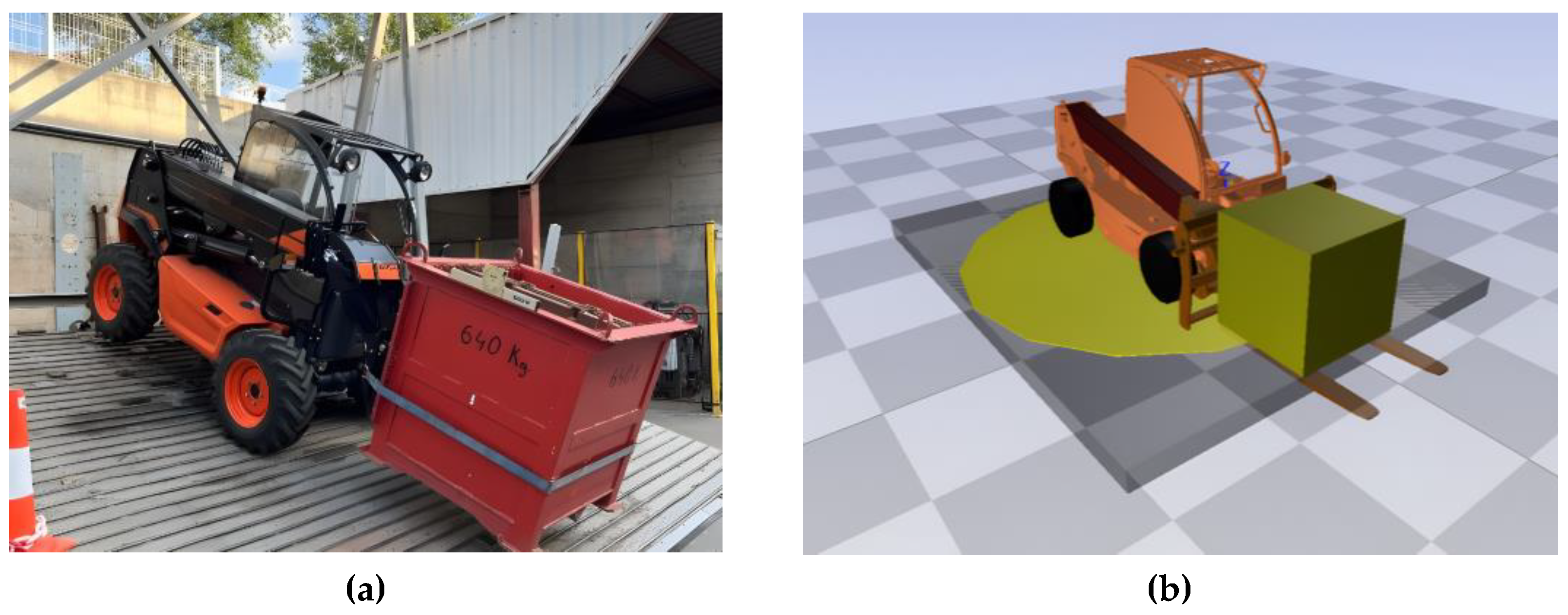
Figure 2.
Schematic representation of the stability pyramid.
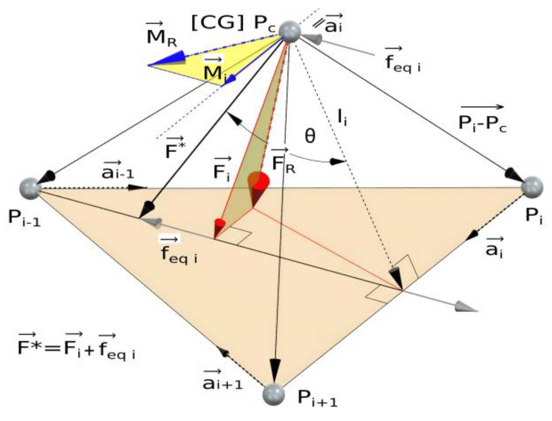
Figure 3.
Schematic diagram of the telehandler used in the quasi-static model. (a) Positions of the front and rear axles, the front-left and front-right wheels, the rear axle articulation point and the centre of gravity (CG). (b) Reference frames, inclination of the supporting plane (Lift Platform) and orientation of the telehandler (Rotatory Platform).
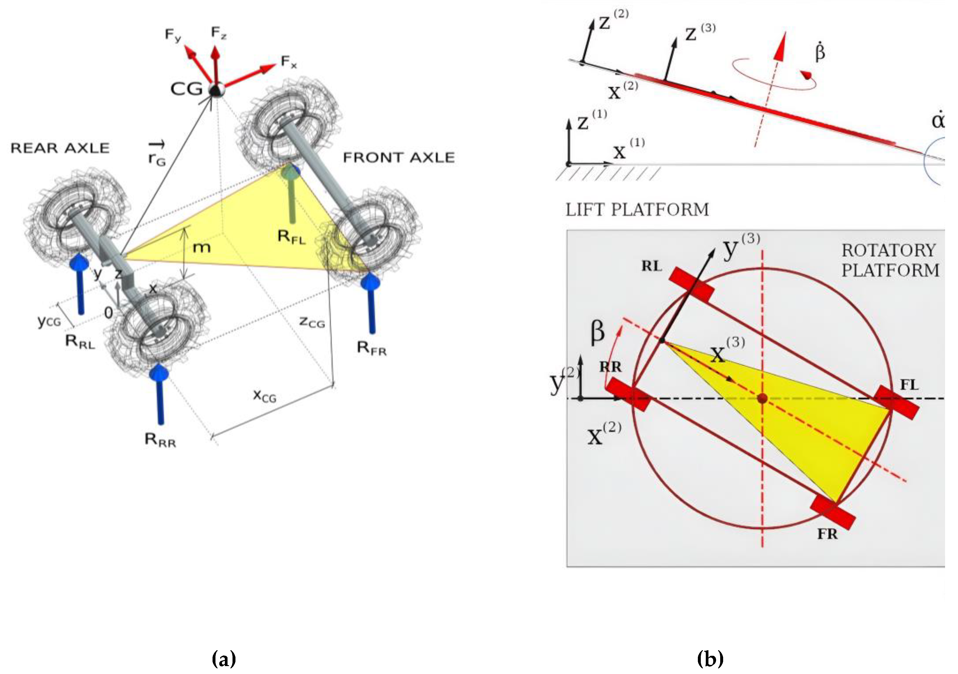
Figure 4.
(a) Vertical reaction forces at the support points FR, FL, and P as functions of the orientation angle β for configuration EP7 (payload 1600 kg, boom angle 25°, minimum extension, platform inclination α = 9.6°). Solid lines correspond to gravitational forces only, while dashed lines include additional global inertial effects (, ) (b) The right-hand plot shows the difference between both cases, highlighting the contribution of inertial forces to load transfer.
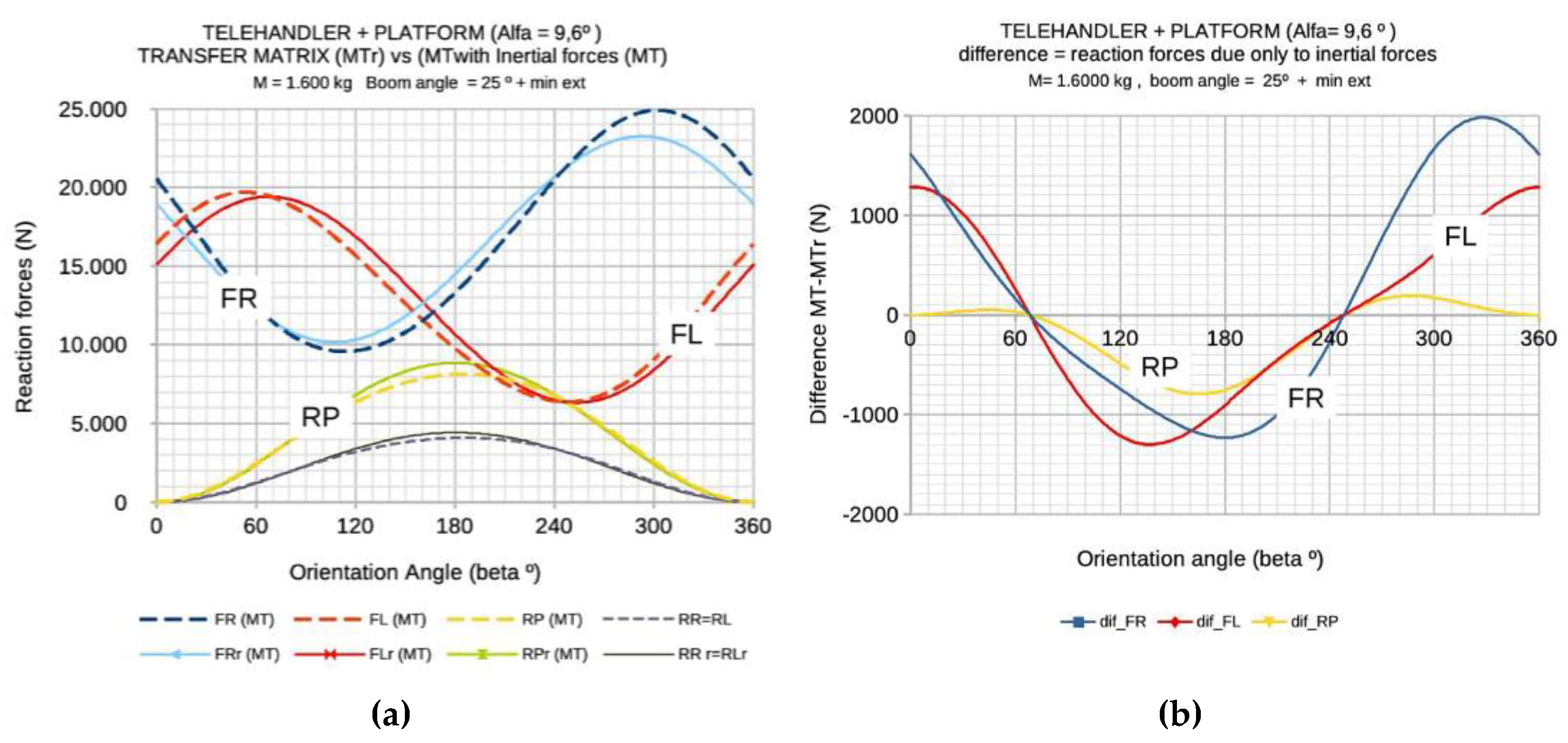
Figure 5.
(a) Structural schematics used for analysing lateral rollover in the telehandler. (a) Initial and rotated positions of the rear axle as the frontal chassis rolls about the virtual axis V1, defined by (points P-A), (b) Simplified representation (it’s not to scale for better viewing) showing the two rollover axes: the virtual roll axis V1 and the effective rollover axis V2, defined by the ground-contact points of the right-hand wheels.
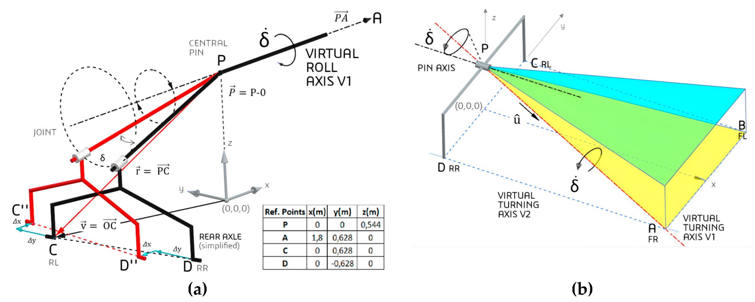
Figure 6.
Flowchart of the geometric procedure used to model the rear-axle kinematics during Phase I of rollover.
Figure 6.
Flowchart of the geometric procedure used to model the rear-axle kinematics during Phase I of rollover.
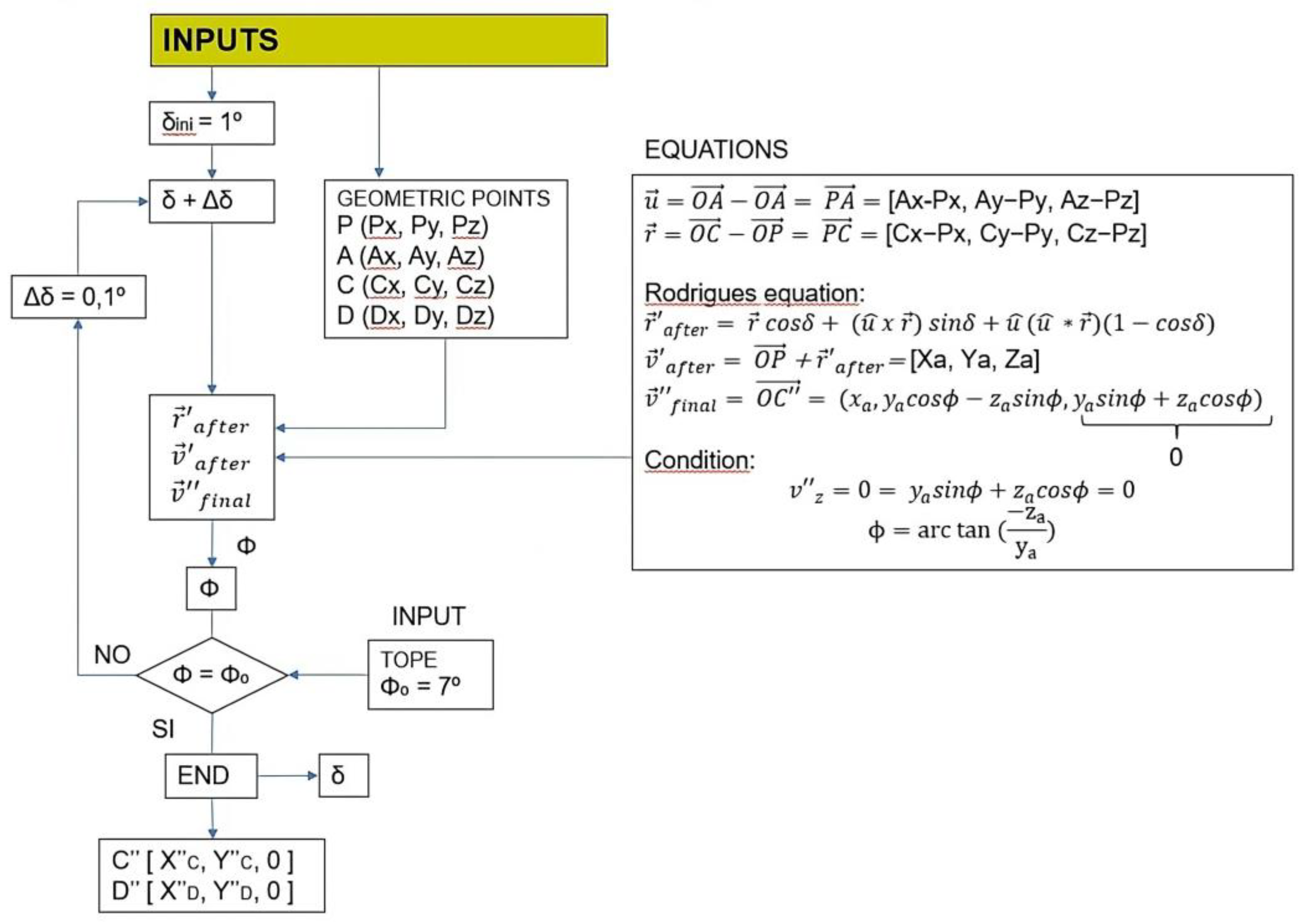
Figure 7.
Multibody virtual BG3D model of the telehandler, according Figure 6 of Puras et al. (2024) [2].
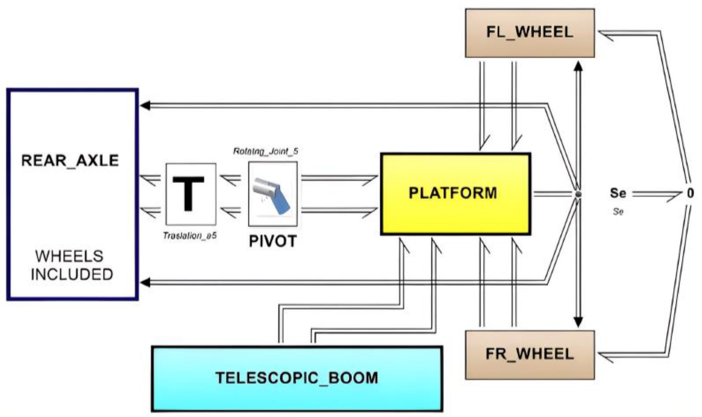
Figure 8.
Multibody virtual BG3D model of the Tilt-Rotary platform and telehandler sub model connected.
Figure 8.
Multibody virtual BG3D model of the Tilt-Rotary platform and telehandler sub model connected.
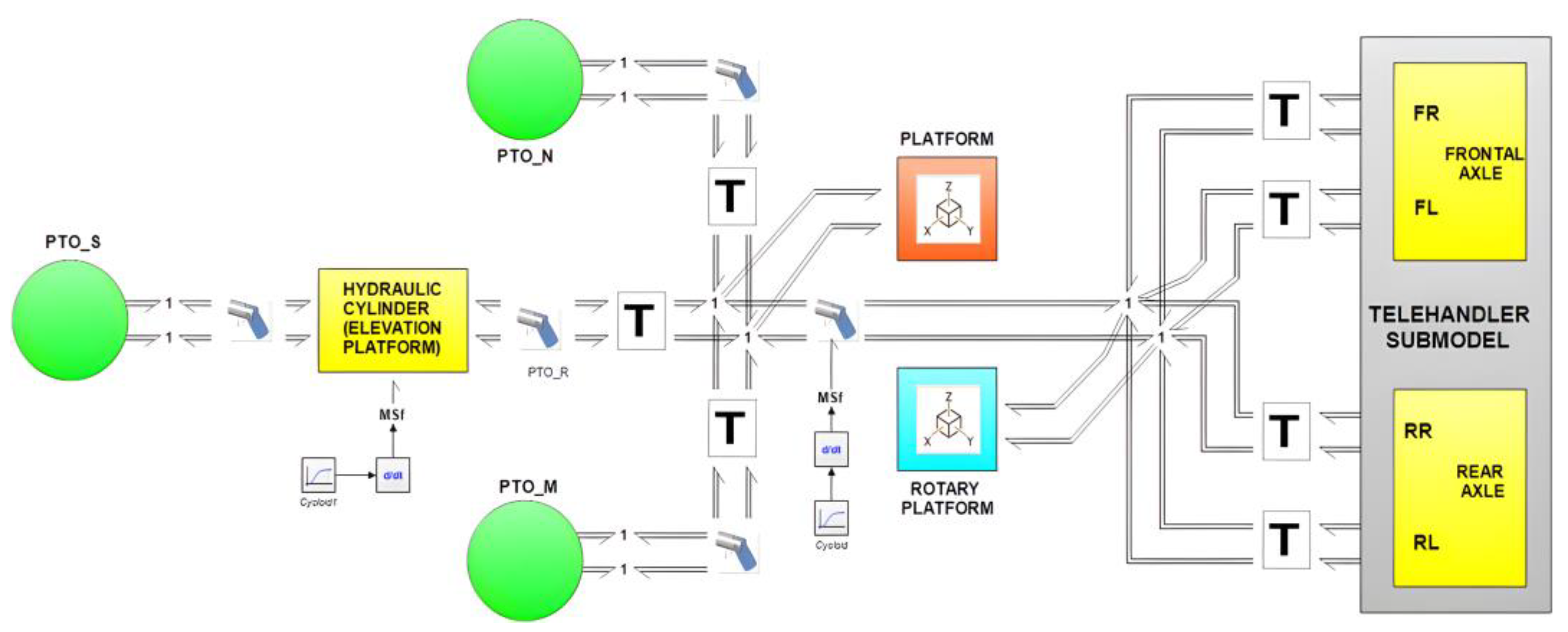
Figure 9.
Vertical reaction forces (z) at each wheel during a full vehicle rotation (β = 0°–360°) on an inclined platform, for specific operating conditions of payload mass = 0 kg, boom elevation angle = 10°, platform inclination angle α = 25° and for different boundary conditions. Boundary conditions: (a) with lateral (y axis) constraints on the right hand wheels and longitudinal (x axis) constraints on both rear wheels. (b) with lateral constraints on the right hand wheels and a longitudinal constraint applied only to the rear right wheel.
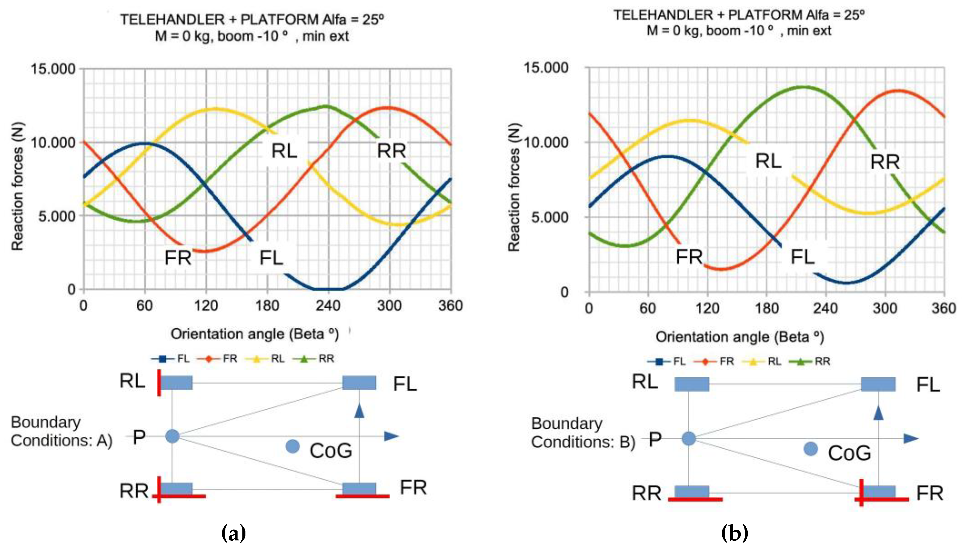
Figure 10.
(a) Comparison of vertical reaction forces obtained using the Transfer Matrix ™ and the Virtual Model (VM) as a function of the orientation angle β. Dashed lines correspond to TM results, while solid lines represent VM results. (b) Discrepancies in the vertical reactions between result s of MT and MV models.
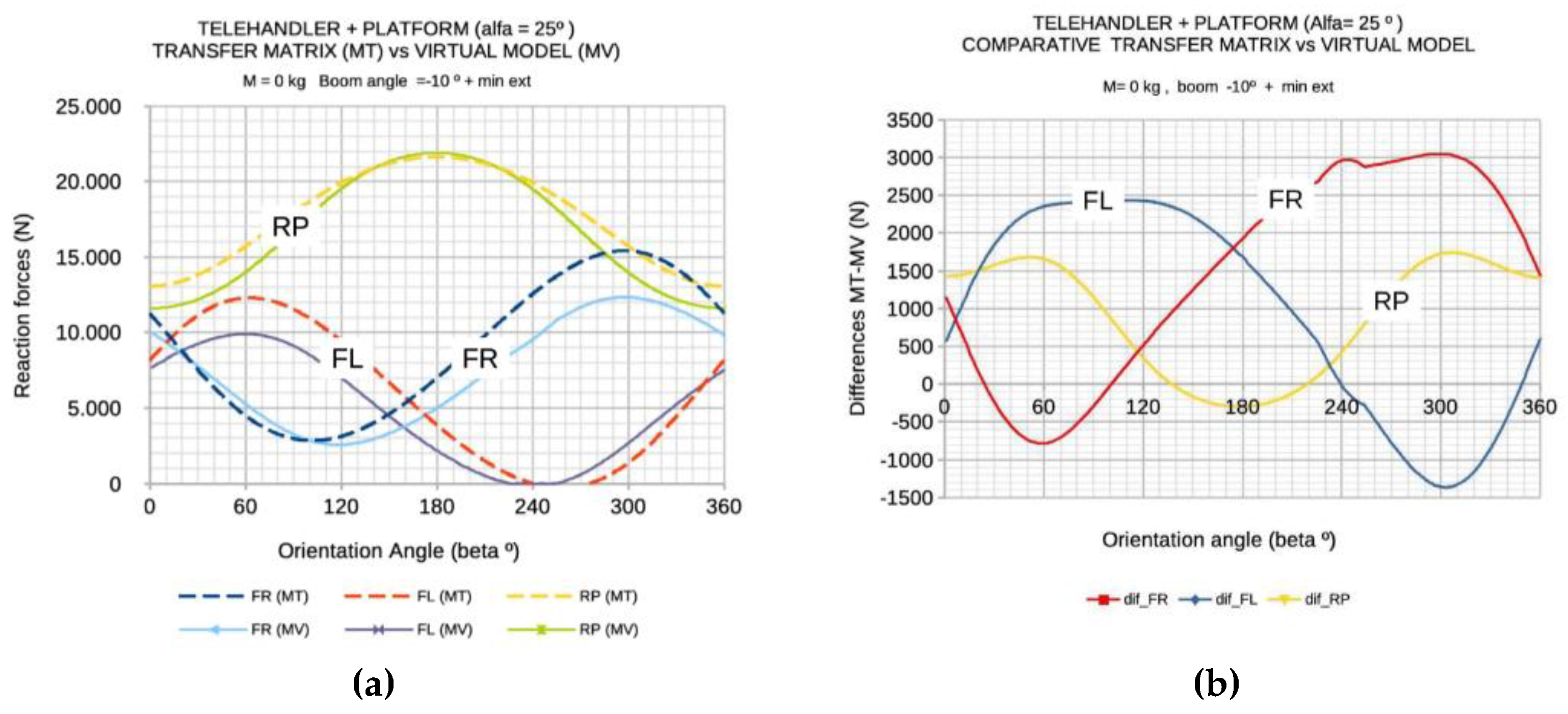
Figure 11.
Evolution of the global centre of gravity (CG) coordinates (X, Y, Z) during boom elevation, considering different telescopic extensions and payload configurations, obtained using the virtual tilt–rotary platform model.
Figure 11.
Evolution of the global centre of gravity (CG) coordinates (X, Y, Z) during boom elevation, considering different telescopic extensions and payload configurations, obtained using the virtual tilt–rotary platform model.
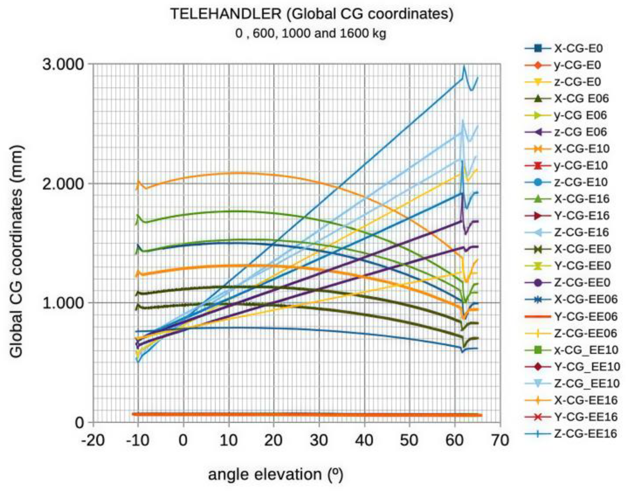
Figure 12.
(a) Inclination platform (b) Example of test on inclination platform: ISO22915 Test 3 configuration.
Figure 12.
(a) Inclination platform (b) Example of test on inclination platform: ISO22915 Test 3 configuration.
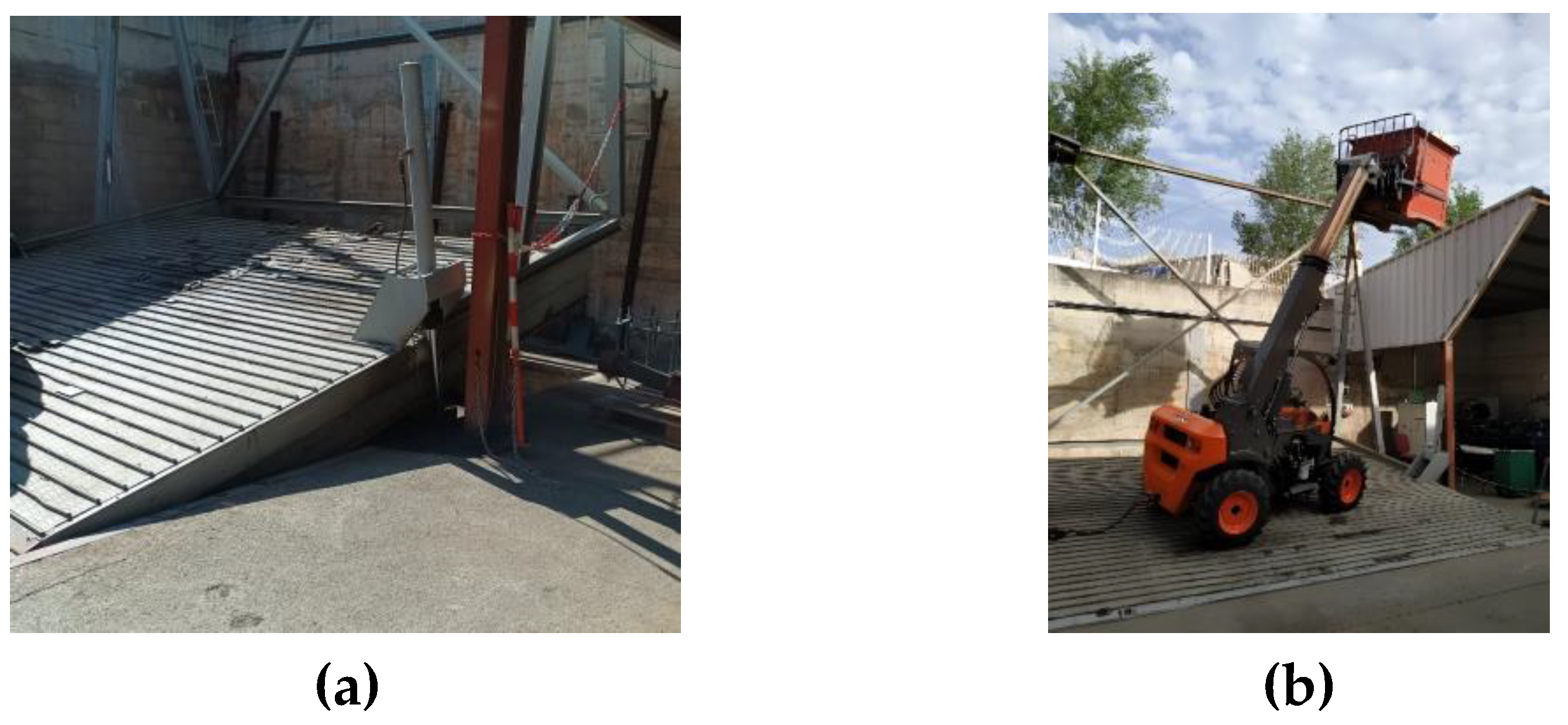
Figure 13.
Experimental calibration curve of the load cell located at the rear axle.
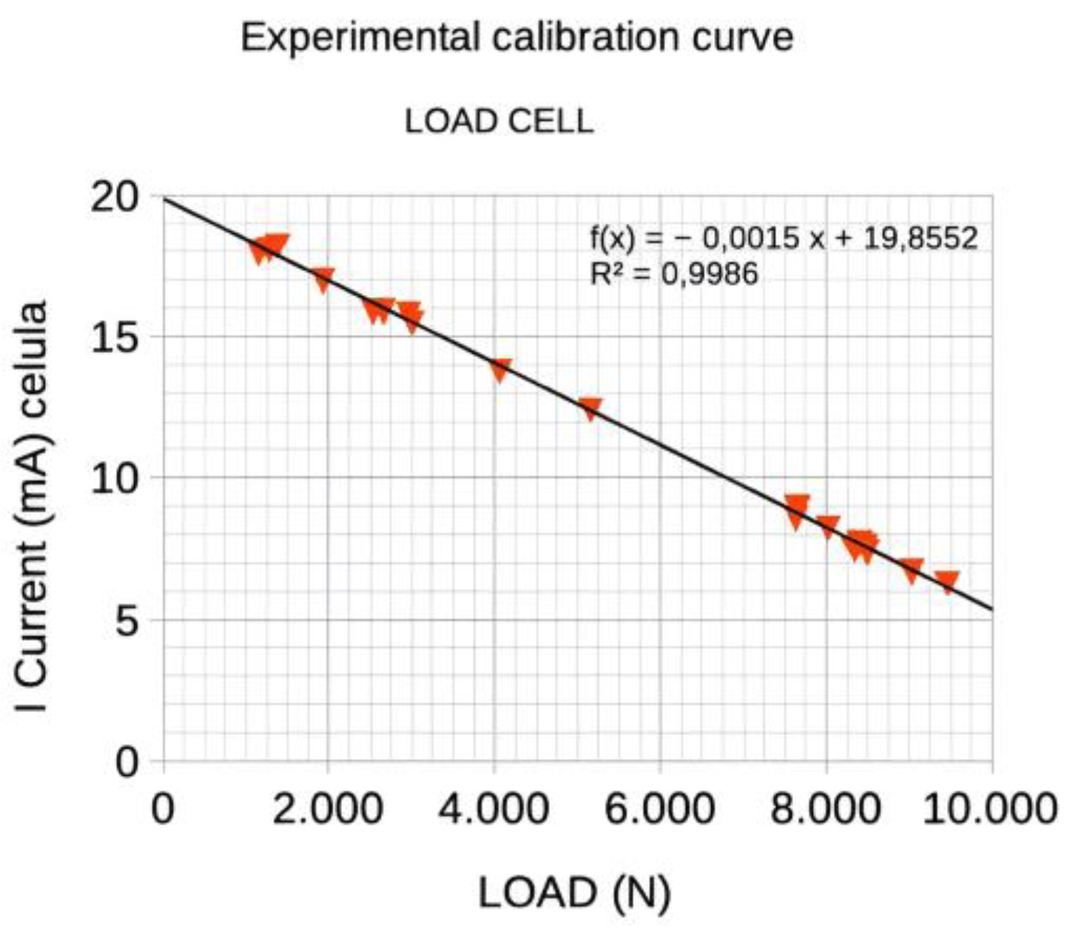
Figure 14.
(a) Test 2: Slope inclination 22%, load 1600kg, Travelling position, Maximum retraction of the boom, full rearward fork. (b) Test 3: Slope inclination 12%, load 1600kg, Maximum inclination and Maximum extension of the boom.
Figure 14.
(a) Test 2: Slope inclination 22%, load 1600kg, Travelling position, Maximum retraction of the boom, full rearward fork. (b) Test 3: Slope inclination 12%, load 1600kg, Maximum inclination and Maximum extension of the boom.
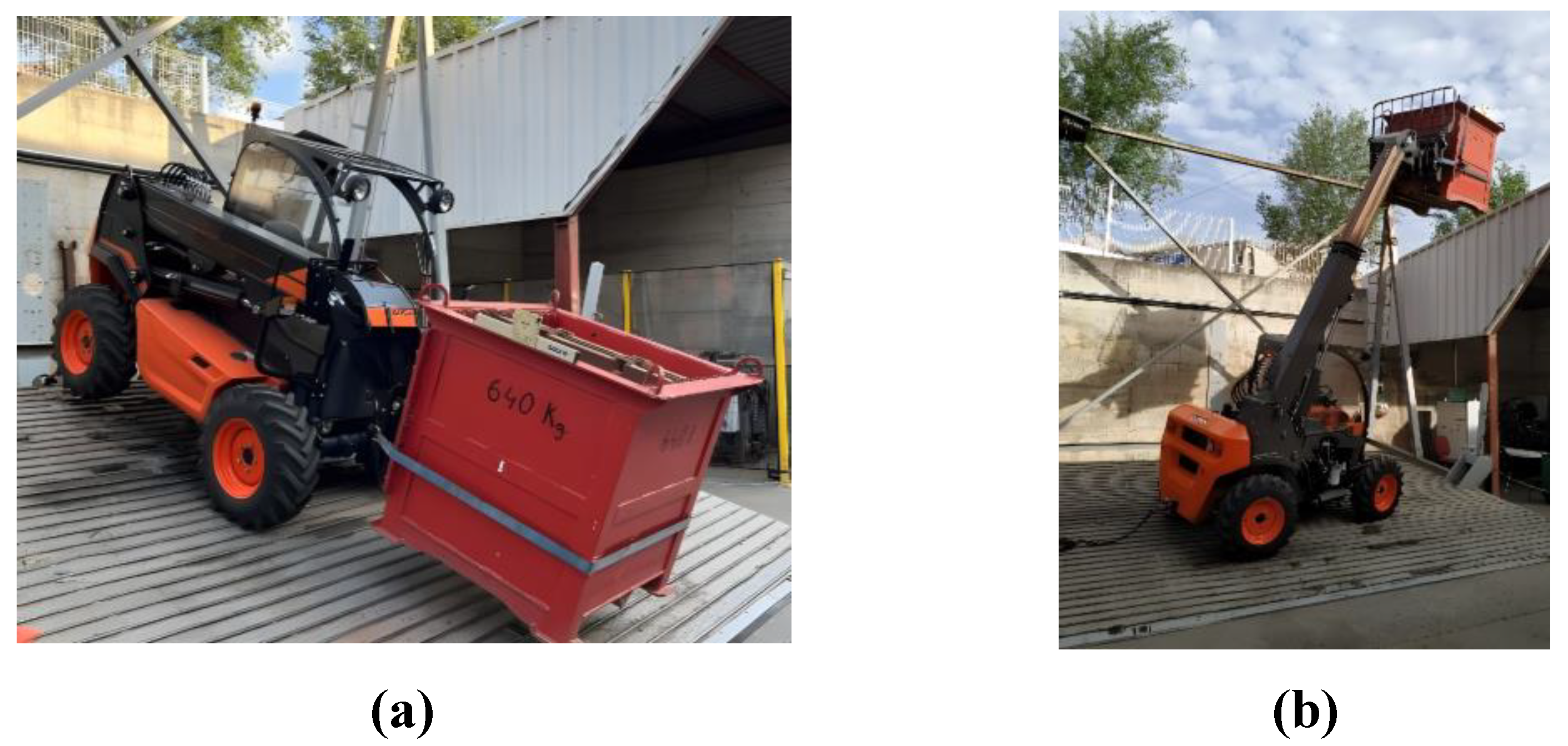
Figure 15.
(a) Test 4: Slope inclination 50%, without load, Travelling position, Maximum retraction of the boom, full rearward fork. (b) Test 5: Slope inclination 10%, without load, Maximum inclination and Maximum extension of the boom.
Figure 15.
(a) Test 4: Slope inclination 50%, without load, Travelling position, Maximum retraction of the boom, full rearward fork. (b) Test 5: Slope inclination 10%, without load, Maximum inclination and Maximum extension of the boom.
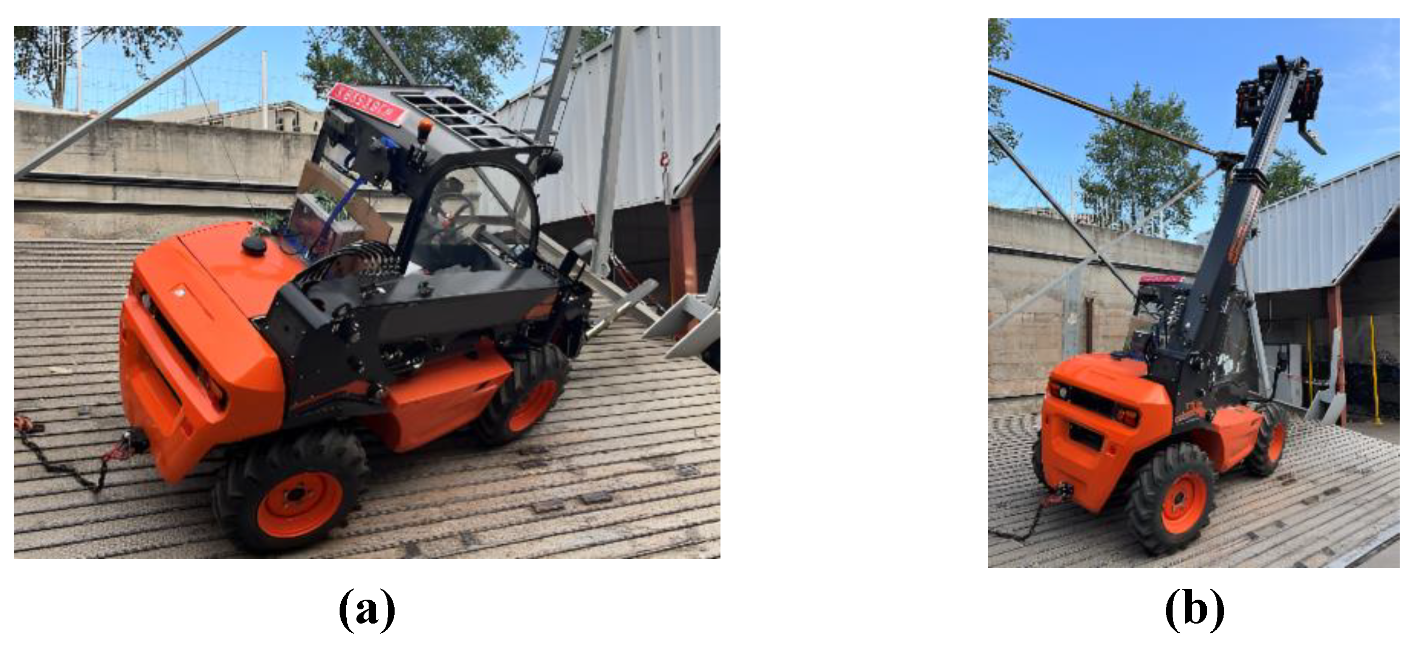
Figure 16.
Type 1 Test according to ISO 22915-14. (a) Evolution of the left rear wheel reaction (RL) obtained with the virtual model for different initial configurations. (b) Normalized results: com-parison between experimental values, virtual model, and ISO normative limit.
Figure 16.
Type 1 Test according to ISO 22915-14. (a) Evolution of the left rear wheel reaction (RL) obtained with the virtual model for different initial configurations. (b) Normalized results: com-parison between experimental values, virtual model, and ISO normative limit.
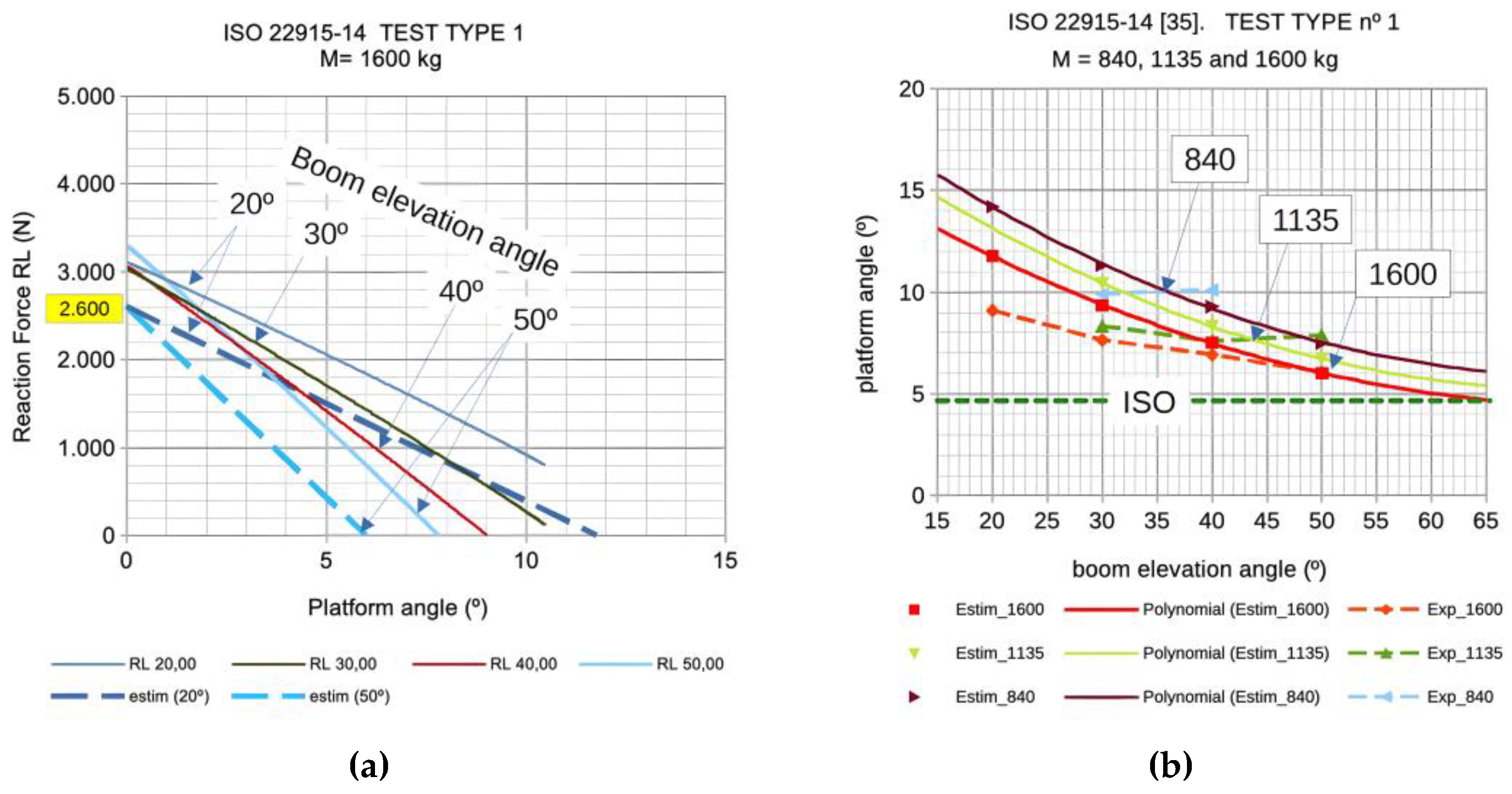
Figure 17.
Type 2 Test according to ISO 22915-14. (a) Relationship between boom elevation angle and fork heel height obtained with the virtual model. (b) Left rear wheel reaction (RL) versus platform inclination angle: comparison between virtual model, ISO normative limit (green point), and experimental result with load cell threshold (black point).
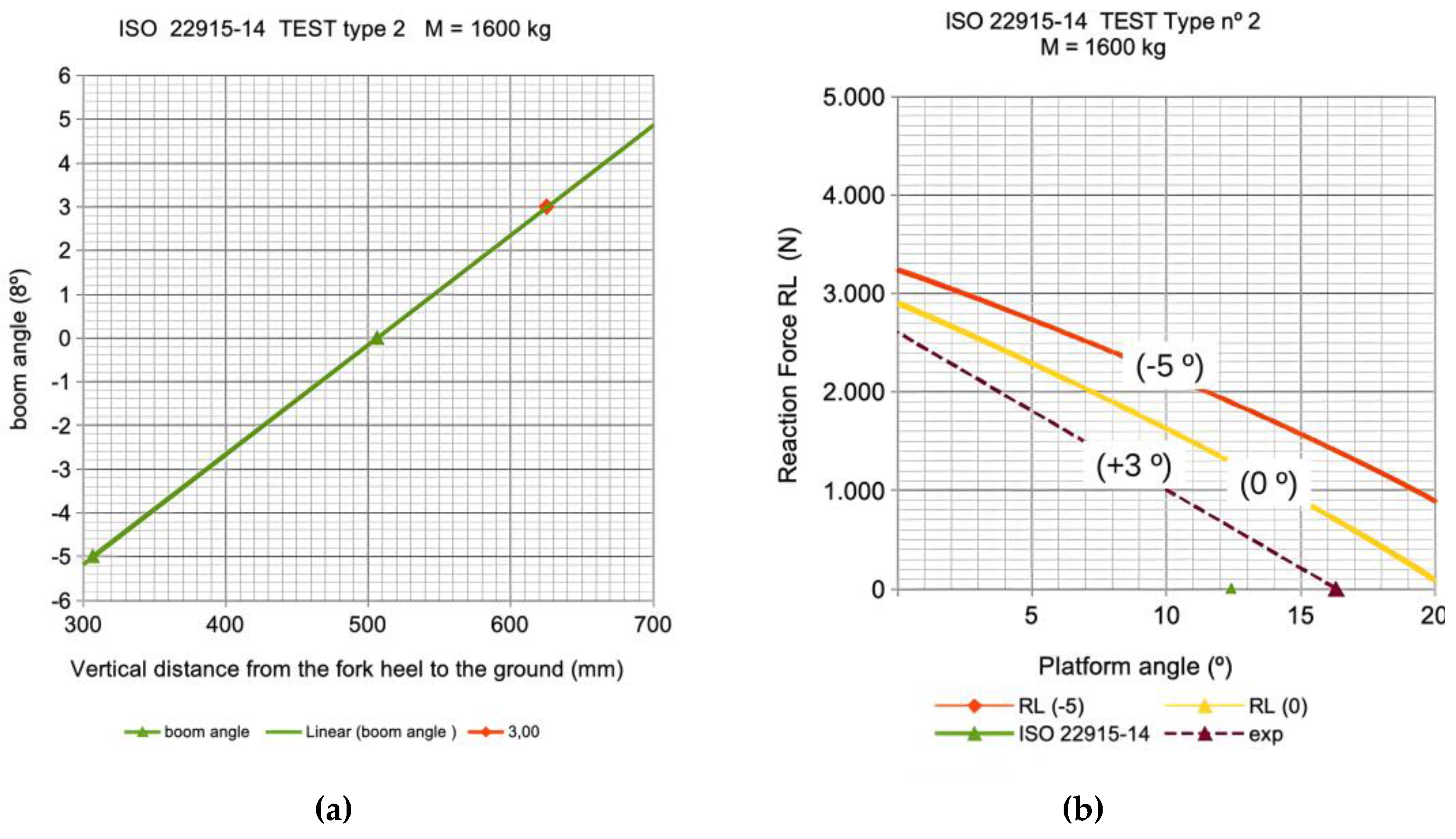
Figure 18.
Type 3 and 5 Test according to ISO 22915-14. (a) Wheel reactions as a function of machine orientation for the Type 3 Test (1600 kg) and Type 5 Test (0 kg), with maximum boom eleva-tion (62°) and full extension. (b) Wheel reactions as a function of orientation for the Type 3 and Type 5 Tests with boom elevation reduced to 52° and full extension.
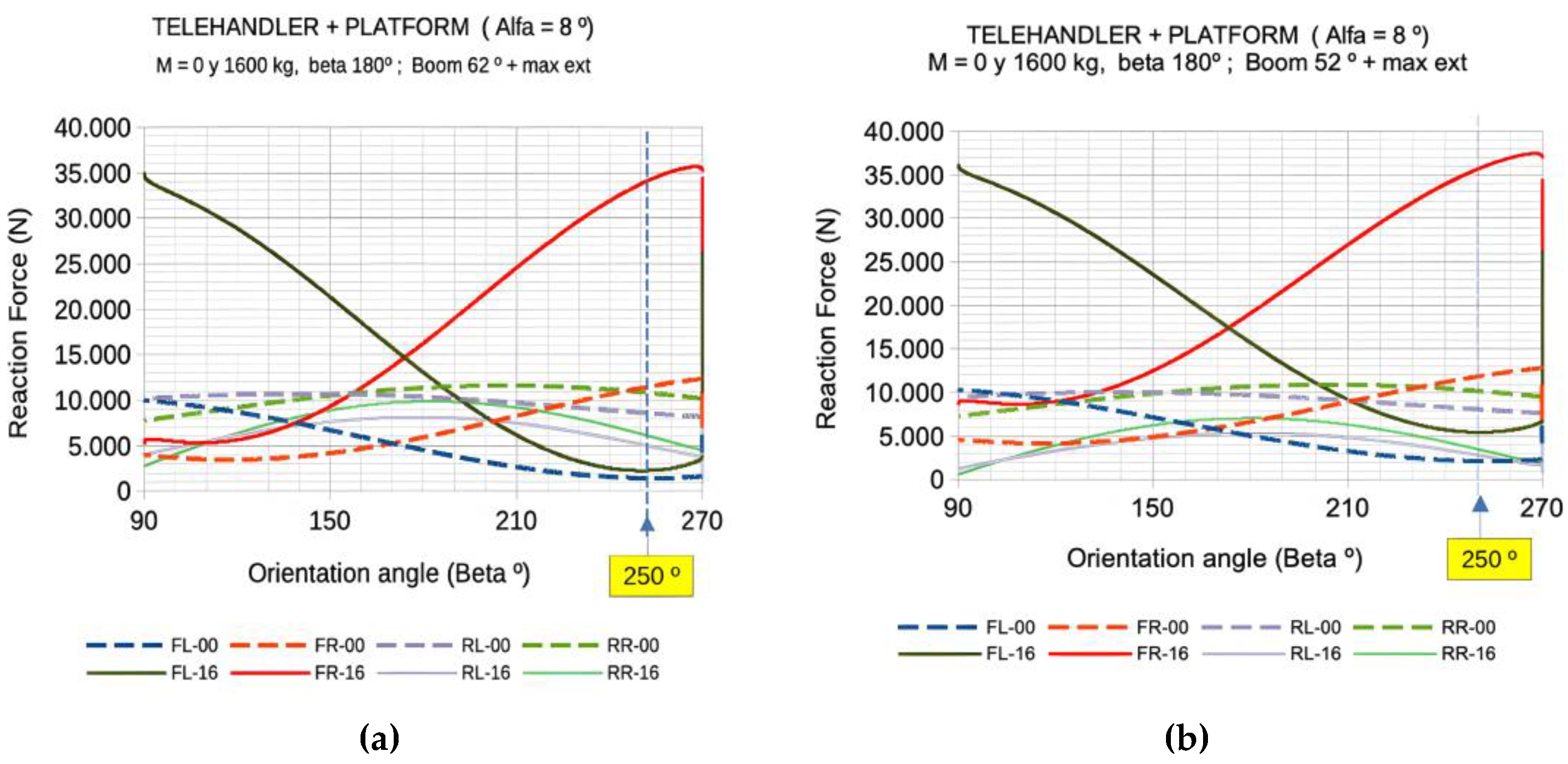
Figure 19.
Type 4 Test according to ISO 22915-14. Virtual model results for (a) Configuration A: rear axle rigidly connected to the front chassis, and (b) Configuration B: freely articulated rear axle. Wheel reactions are shown as a function of platform inclination angle, highlighting critical angles associated with rollover axes V1 and V2.
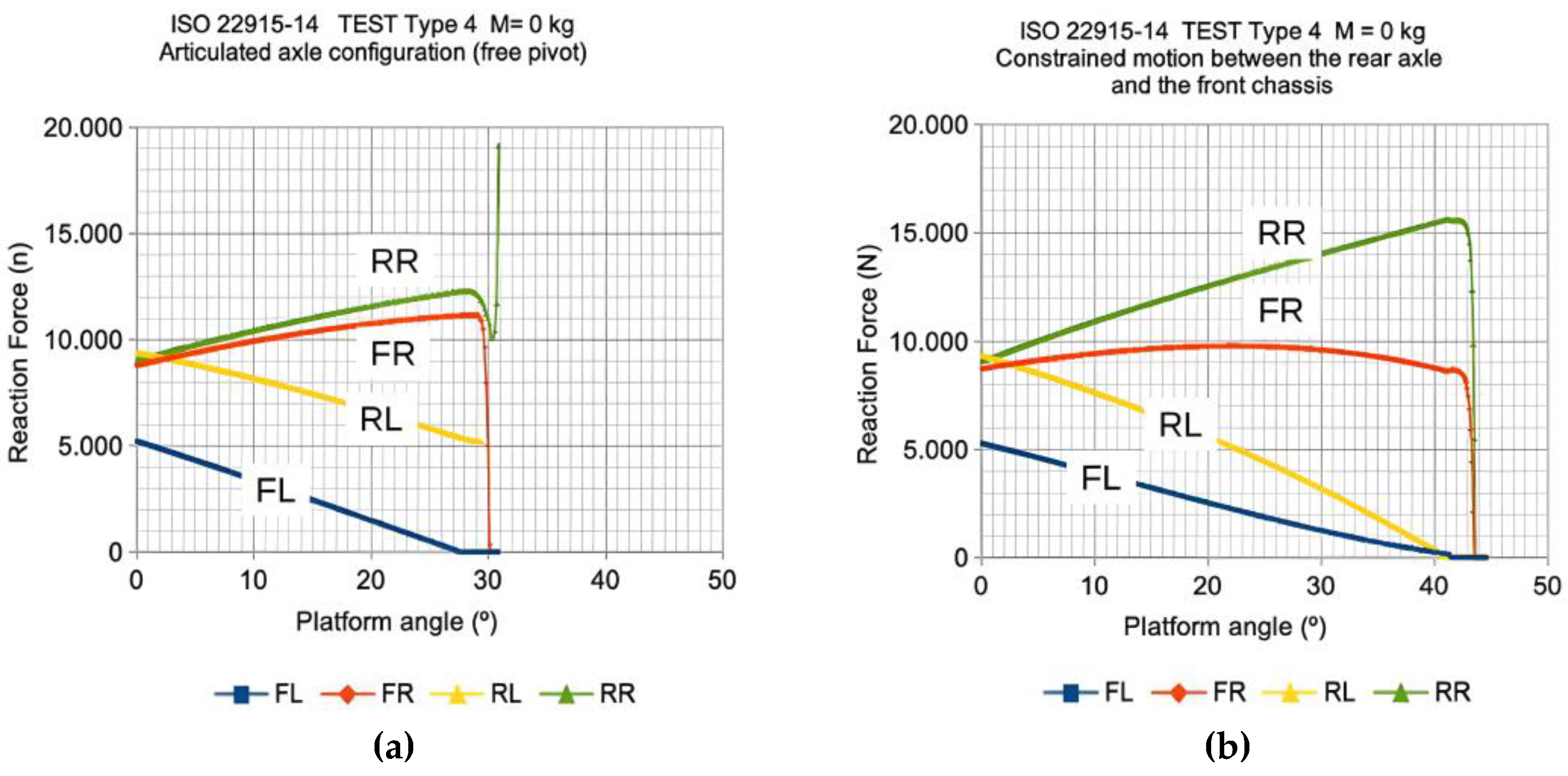
Figure 20.
Type 4 Test according to ISO 22915-14. Virtual model results for configuration C with pivot mechanical stop (±7°): (a) geometric evolution of the articulation, and (b) evolution of wheel reactions on the left side. The transition between the lateral stability mode de-fined by axis V1 and the mode associated with axis V2 after stop contact is observed.
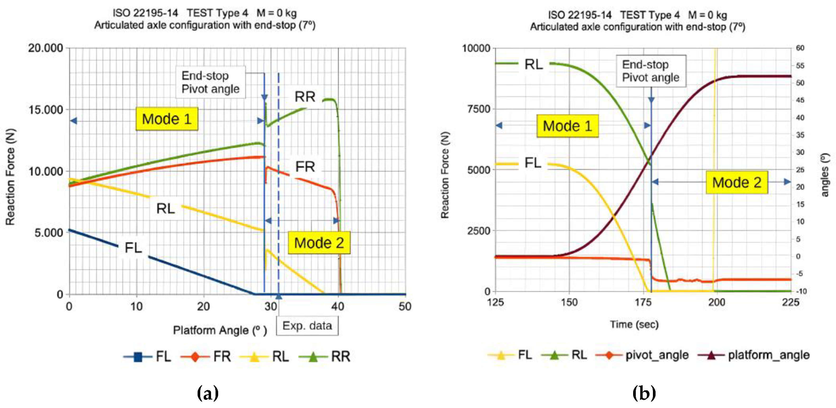

Table 1.
Comparative overview of model-based stability assessment methods.
| Type of model | Required data | Main objectives | Main Limitations |
| Kinematic | Dimensions, CG location, boom and axle geometry (temporal evolution) | Early-stage feasibility, reach and clearance analysis, conceptual design checks | Ignores forces, deformations, dynamics |
| Quasi-static | Mass properties, load distribution, tire stiffness | Static slope limits, max. safe loads, compliance with static homologation criteria | No inertial or transient effects |
| Dynamic multibody | Full inertial properties, stiffness/damping, terrain profile, operator model (optional) | Transient maneuver analysis, active control evaluation, rollover prediction | High computational cost, requires calibration |
Table 2.
Comparative overview of experimental stability assessment methods.
| Method | Main outputs | Key applications | Main Limitations |
| CG determination (dual weighing, pendulum, tilt table) | CG coordinates | Model input, design verification, regulatory compliance | Requires controlled conditions, specific equipment |
| Tilt/Rollover testing (adjustable platform) | Angle or acceleration at loss of stability | Homologation (ISO16231, ISO789.6, ISO22915), validation of operational limits | Potential risk to equipment, time-consuming |
| Hybrid or hardware-in-the- loop platforms | Dynamic response under variable parameters | Controller calibration, operator-machine-terrain interaction studies | High equipment cost, operational complexity |
Table 3.
Calculation stability pyramid template: inputs (left) and outputs (right).
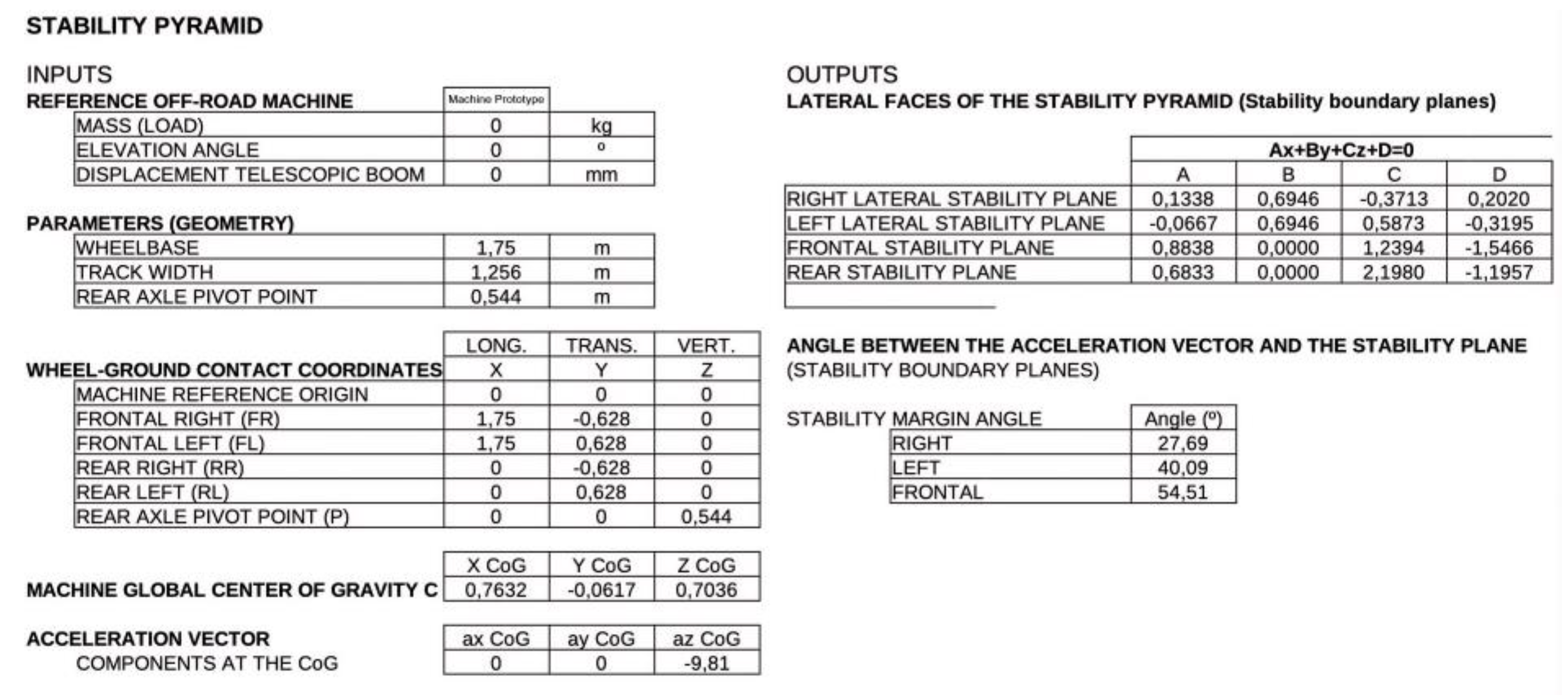 |
Table 4.
Stability results for different operating conditions of the machine.
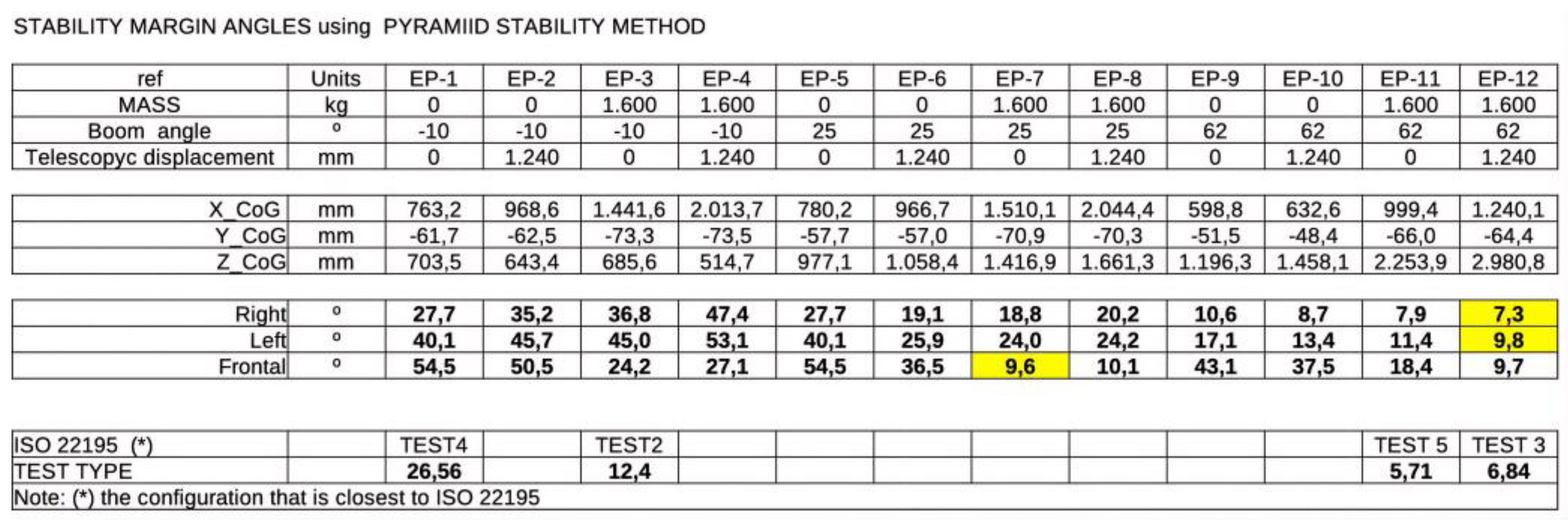 |
Table 5.
Relative displacements of the rear-wheel ground-contact points C (left) and D (right) obtained from the kinematic model.
Table 5.
Relative displacements of the rear-wheel ground-contact points C (left) and D (right) obtained from the kinematic model.
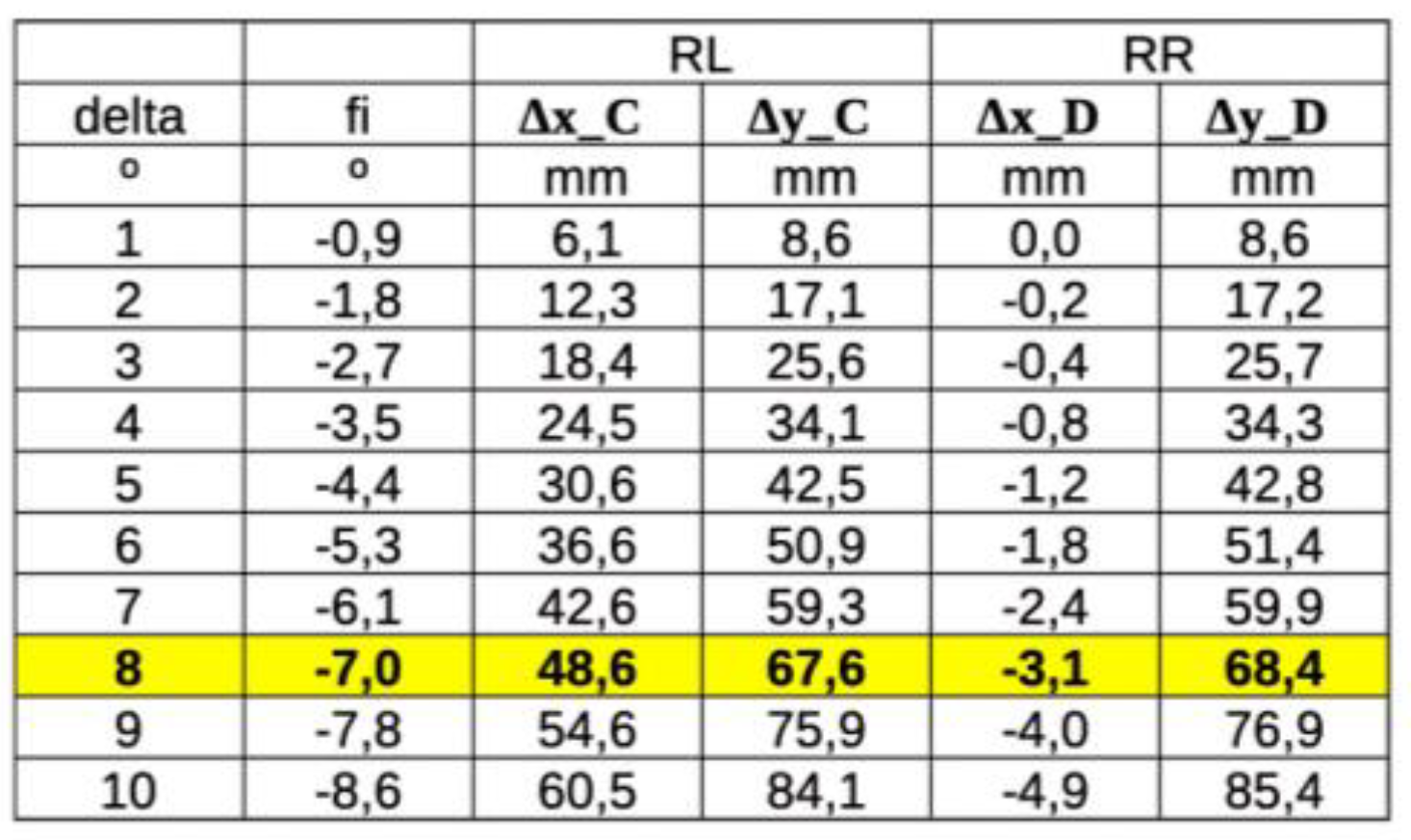 |
Table 6.
ISO22915 Test1 stability experimental results (load cell cut).
| Load (kg) | Boom inclination angle (º) |
Platform Inclination (%) |
Boom extension (mm) |
| 1.600 | 20 | 16 | 13 |
| 30 | 13,4 | 132 | |
| 40 | 12,1 | 343 | |
| 50 | 10.6 | 693 | |
| 1.135 | 30 | 14,6 | 621 |
| 40 | 13,3 | 915 | |
| 50 | 13,8 | 1240 | |
| 800 | 30 | 17,4 | 1100 |
| 40 | 17,8 | 1240 | |
| 0 | 10 | >18 | 1240 |
| 20 | >16 | 1240 |
Table 7.
ISO22915 Test2,3, 4 and 5 stability experimental results.
| Test number | Mass (kg) | Min. Platform Inclination required (%) | Platform Inclination obtained (%) | Platform Inclination obtained (°) |
| Test 2 | 1600 | 22 % | 29,30 % | 16,33 ° |
| Test 3 | 1600 | 12 % | 14,30 % | 8,14 ° |
| Test 4 | 0 | 50 % | 60,40 % | 31,13 ° |
| Test 5 | 0 | 10 % | 13,8 % | 7,86 ° |
Disclaimer/Publisher’s Note: The statements, opinions and data contained in all publications are solely those of the individual author(s) and contributor(s) and not of MDPI and/or the editor(s). MDPI and/or the editor(s) disclaim responsibility for any injury to people or property resulting from any ideas, methods, instructions or products referred to in the content. |
© 2026 by the authors. Licensee MDPI, Basel, Switzerland. This article is an open access article distributed under the terms and conditions of the Creative Commons Attribution (CC BY) license (http://creativecommons.org/licenses/by/4.0/).
Copyright: This open access article is published under a Creative Commons CC BY 4.0 license, which permit the free download, distribution, and reuse, provided that the author and preprint are cited in any reuse.


