Submitted:
19 January 2026
Posted:
20 January 2026
You are already at the latest version
Abstract
The stability and performance of drones are seriously affected by vibrations originating from propellers. These vibrations can lead to structural resonance, decreased sensor accuracy, and reduced flight safety. In this study, drone propeller vibrations are modeled and analyzed using differential equations, Laplace transform, and Fourier analysis. The propeller system is represented by single-degree-of freedom (SDOF) and multi-degree-of-freedom (MDOF) mechanical models, and the transfer function of the system is obtained using the Laplace transform. Experimental vibration data collected from the acceleration sensor(ADXL345) is analyzed using Fast Fourier Transform (FFT) using software written in the Arduino IDE application with the ESP32 development board, to determine dominant frequencies and possible resonance states.
Keywords:
drone vibration
; FFT
; resonance analysis
I. Introduction
The project aims to mathematically model the drone propeller system using differential equations, determine the amplitude of acceleration data using FFT (Fast Fourier Transform), and analyze the data to identify dominant vibration frequencies and potential resonance points. Drone vibrations occur as a result of the periodic forces generated by the rotational motion of the propellers being transmitted to the airframe. Dynamic system equations based on Newton’s second law are applied to model these vibrations. Fourier analysis is an important method that allows for the decomposition of vibration signals obtained in the time domain into their frequency components. By converting vibration data measured in the time domain or obtained in simulation to the frequency domain using the Fourier transform [1], it is possible to determine the frequency at which the drone resonates by observing the highest frequency values. The obtained results will contribute to the analysis and control of drone vibrations. By analyzing the vibrations generated by drone propellers using Fourier analysis, potential problems can be prevented. The design of project scope covers the ensuing areas which are system Description and Modeling:
- ⮚
- Generating discriminational equations for Single- Degree- of- Freedom( SDOF) and Multi-Degree-of-Freedom( MDOF) systems
- ⮚
- Data Acquisition and Measurement
- ●
- Recording vibration data with (ADXL345).
- ●
- Data collection at different rotor pets and flight scripts.
- ⮚
- Signal Processing and Analysis
- ●
- Frequence diapason birth using Fourier/ FFT analysis.
- ●
- Discovery of harmonious factors and blade- pass frequence.
- ●
- Noise insulation and data preprocessing
- ●
- Natural frequence and Resonance Analysis,computation of system natural frequentness.
- ⮚
- Determination of resonance states
- ●
- Separation of structural and aerodynamic vibration.
System analysis is critical, particularly regarding issues similar as vibration, resonance, and structural strength. Drone factors similar as propellers, machines, airframes, and detectors interact with each other. A proper understanding of these relations enables both fine modeling of system dynamics and accurate interpretation of real- world flight data.[2]System analysis provides the necessary foundation for the accurate operation of fine styles similar as discriminational equations, Laplace transforms, and transfer functions. likewise, assaying experimentally collected vibration data with FFT helps understand system geste at a frequence position. Using these two approaches together enables the identification of critical frequentness, resonance regions, and implicit failure within the system with high delicacy.Understanding system dynamics in both time and frequency domains is crucial when investigating drone propeller vibrations. Therefore, the project utilized Laplace transform and Fourier analysis (FFT). The Laplace transform enabled the time domain differential equations of the drone propeller-motor system to be transferred to the frequency domain and enabled the transfer function of the system to be obtained. The Fast Fourier Transform (FFT) method was used to process real-world vibration data obtained from the drone,[3]. The propeller and engine-generated vibrations were measured in the time domain but converted to the frequency domain to accurately understand system behavior.
Artificial intelligence( AI) plays a critical part in ultramodern drone systems, both at the data processing, vaticination, and decision support situations. It complements traditional signal processing styles( FFT, modal analysis, filtering, etc.) and significantly improves performance in some areas. Traditional FFT spectra are fed into AI models as feature input.
There are some applications such as automatically finding resonance peaks from the spectrum,learning relationships between harmonics,classifying changes in blade-pass frequency,data compression (feature extraction),Al models can make more accurate predictions by processing combined FFT and time series data.
A “digital twin” of the drone can be created that It helps a mathematical model fed with real flight data,a virtual drone model.Thus,These provide to simulate natural frequencies and predict vibration amplification.
II. Literature Rewiev
In the field of modeling drone propeller vibrations using differential equations, studies, research, and articles are available in the literature, including determining vibrations between the propeller/rotor systems and the fuselage in multi-rotor UAVs, obtaining frequency data from the fuselage and propeller systems, and adjusting engine speed, as well as examining parameters such as propeller speed changes and load changes.
In the field of using Fourier analysis to determine resonant frequencies, the modulation generated as the propeller rotates was captured from the laser optical signal and applied the Fourier transform to determine the fundamental frequency (rotational speed),[2] a modal analysis was performed for the propeller, and natural frequencies were determined. The literature also includes studies and research on frequency analysis of time-delayed nonlinear systems[4], and the conversion of time-domain vibration signals to the frequency domain using Fourier analysis. Lee et al. (2020) modeled drone vibrations using differential equations using SDOF and MDOF models and analyzed the system response using the Laplace transform. Such studies have constituted important references in the mathematical expression of drone dynamics and have made significant contributions to determining safe operating ranges by determining the resonance tendencies of drone systems.
III. Problem Definiton
Drone propellers create periodic vibrations at high speeds. If the frequency of these vibrations is close to the system’s natural frequency, resonance occurs. High resonance and vibration can lead to engineering problems such as sensor and camera data corruption, decreased flight stability, component problems and failures, and energy inefficiency. To address these issues, balancing to prevent propeller imbalance, changing material selection, monitoring vibration data, and analyzing data using a Fourier transform to identify the source of resonance can help take precautions.
The drone propeller- motor- body structure is a complex dynamic system where aerodynamic and mechanical forces performing from rotational stir are transmitted to the body. The forces generated by the propeller’s gyration, the electromechanical geste of the motor, and the elastic structure of the body combine to produce amulti-component vibration pattern on the drone.Thus, the system is studied as a mechanical vibration that can be modeled both physically and mathematically. During flight, the motors rotate at high speeds, driving the propellers and generating lift. However, due to motor-propeller imbalances, assembly errors, or aerodynamic asymmetries, periodic stresses are transmitted to the airframe. These forces create vibrations in the drone’s arms and body.
Adxl345 acceleration sensor was used to measure the vibration data on the propellers and ESP32 development board was used to observe the data via the mobile application. With the software written in C/C++ language in the Arduino IDE software application, the acceleration data from the adxl345 sensor will be converted with the forier transform and will be included as fft amplitude in the mobile application.
The scope and boundaries of the system analyzed in this study are clearly defined:
- ❖
- Components Included in the Analysis
- ○
- Propeller (airfoil, mass, aerodynamic load)
- ○
- Engine (electromagnetic moment, bearing effects)
- ○
- Engine-body connection (vibration transmission path)
- ○
- Local flexible areas of the drone body
- ○
- Sensor measurement points
- ○
- These components directly affect the dynamic structure of the system.
- ❖
- Components Not Included in the Analysis
- ○
- Flight control algorithms
- ○
- Electronic systems such as GPS, cameras, and telemetry
- ○
- Battery internal chemical processes
- ○
- External impact/damage scenarios
- ○
- Aerodynamic nonlinear stall effects at very high speeds
IV. Mathematical Method
Drone vibration behavior is fundamentally linked to the components between the propellers, motor connections, and fuselage structure. This study addresses modeling drone propeller vibrations using differential equations and using the Forier method to observe and determine resonance frequency values. The project utilizes an ADXL345 acceleration sensor and an ESP32 development board. Acceleration data were obtained by placing the ADXL345 acceleration sensor at specific points on the drone to measure acceleration. The ESP32 development board’s Wi-Fi capability allows data to be monitored both on a computer and remotely from mobile devices. Using software written in C/C++ in the Arduino IDE, acceleration data was observed on a three-axis serial monitor display, along the x, y, and z axes.Also,FFT results about vibration can observe mobile phone.Code was written to observe the frequency data, and frequency values were obtained on a serial plotter display. Vibration signals generated during drone operation are obtained from acceleration or displacement data recorded in the time domain. These signals are typically complex, multi-component, and aperiodic. The Fourier Transform is used to identify vibration sources and detect resonance effects. Discrete Fourier Transform (DFT) or Fast Fourier Transform (FFT) is used for vibration data. The resulting amplitude spectrum, ∣X(ω)∣, represents the high-frequency value in the drone system.Resonant frequencies are defined as distinct peaks in the amplitude spectrum. As the drone’s vibration movements increase, frequency increases are observed. If the drone’s frequency peak exceeds certain limits, it can lead to instability. The obtained results help inform vibration mitigation strategies (e.g., counterweight placement, propeller design optimization, or active vibration control).Equations (1-6) shows formula for algorithm.[5]
- ⮚
- This formula converts the acceleration signal from the time domain to the frequency domain.
- ⮚
- Discrete Fourier Transform (DFT)
a[n] → acceleration data (e.g., Ax)
N → total number of samples
k → frequency index
A[k] → frequency spectrum (FFT output)
Calculating the frequency axis
Fs→sampling frequency
fk→actual Hz equivalent of the kth frequency in the FFT
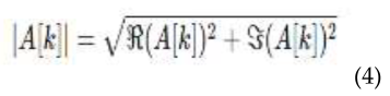
Magnitude Calculation
- ⮚
- Normalized FFT Amplitude
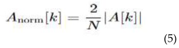
For one-sided spectrum
Resonance Frequency
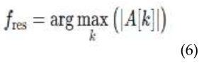
- Highest peaks in FFT
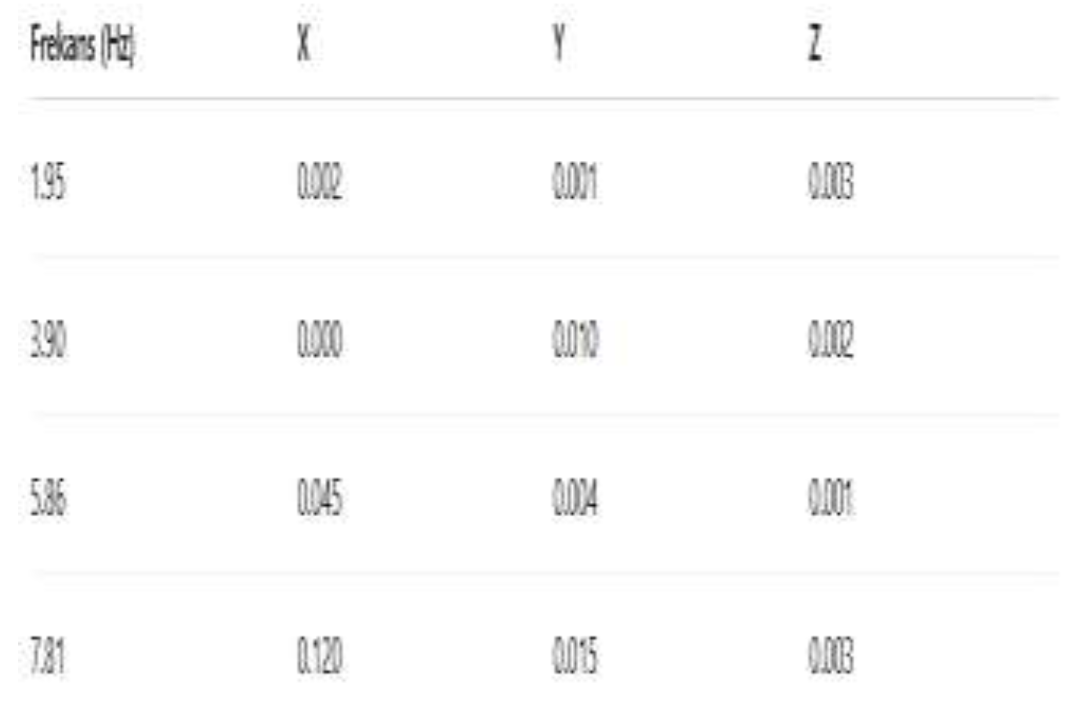
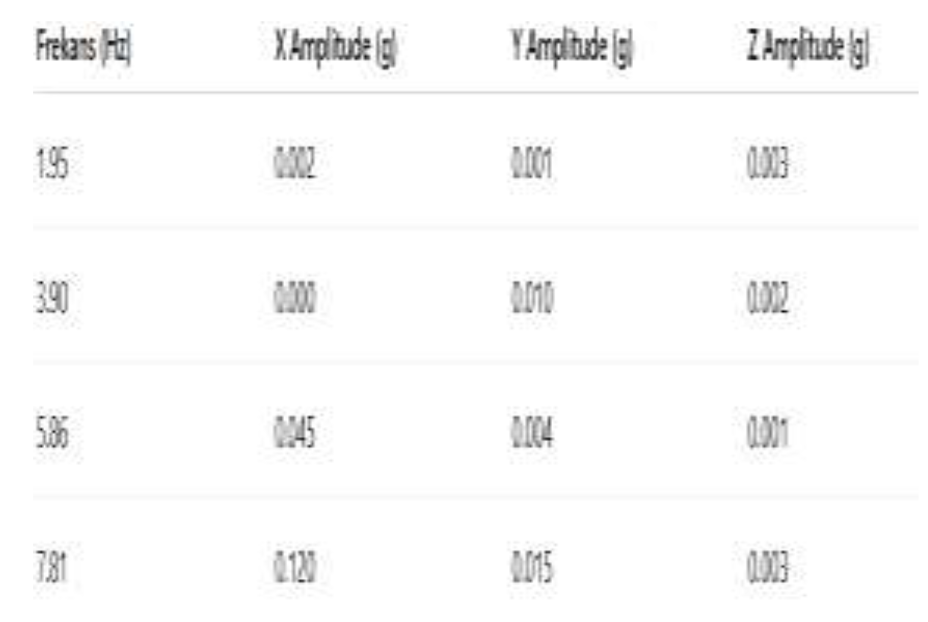
After the sensor calibration adjustment was made, in order to obtain higher and more accurate values, Samples were taken as 256 and the sampling frequency was taken as 500 Hz. The values were noted.
Figure 1.
Frequency X,Y,Z axis.
- ⮚
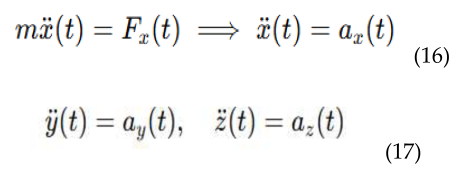
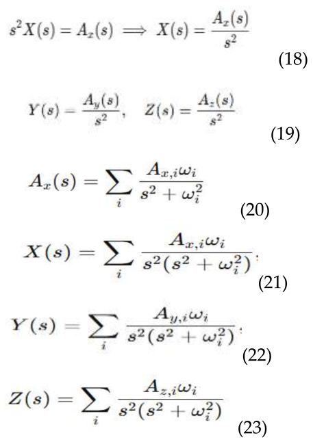
- Model drone propeller vibrations with differential equations.Equations (7-23) shows formula for algorithm.
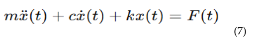
- m → effective mass of the propeller or engine
- c → damping coefficient (air friction + mechanical friction)
- k → elasticity of the propeller or engine mounting (spring coefficient)
- x(t) → vibration displacement
- F(t) → external force/force caused by the rotation of the propeller (e.g., engine shocks)

- ⮚
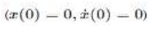
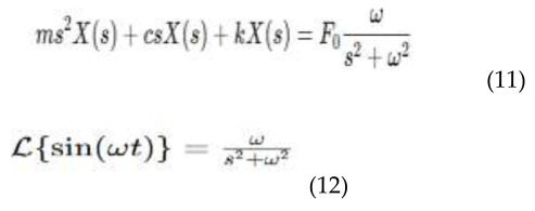
- Laplace Transform

- İnitial
- ⮚
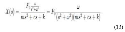
- Transfer Function
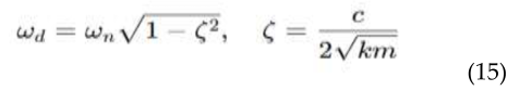
- Natural frequency:
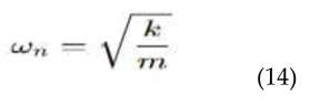
- Damped natural frequency:
- ⮚
- k=0 means the spring coefficient is zero, meaning there is no spring force, only the acceleration from the propeller.
- Laplace
V. Simulation and Implementation
In this study, after the I2C communication of the ADXL345 acceleration sensor with the ESP32 card was established, the software was written in the C/C++ language in the Arduino Ide software program. Acceleration data was observed on the frequency axis by means of FFT.It reads ADXL345 via I2C, collects acceleration data from X-Y-Z axes, performs FFT (with Arduino FFT library), calculates the frequency spectrum, and writes the highest frequency peak to the serial monitor.
- ⮚
-
Setting Up the Simulation Environment
- ●
- Sensor Model Preparation
- ●
- ADXL345 measurement range: ±2g / ±4g / ±8g / ±16g
- ●
- Resolution: 10-bit
- ●
- Data output rate (ODR): 12.5 Hz – 3200 Hz
- ●
- Noise intensity and bandwidth parameters are added to the model.
- ⮚
-
Data Interface Setup
- ●
- I2C or SPI modeling
- ●
- Data readout timing (sample rate) is determined.
- ⮚
-
Simulation Clock Rate and Acquisition Time
- ●
- Recommended sampling frequency: ≥ 2× maximum frequency (Nyquist)
- ●
- Sample: Fs = 2000 Hz for 800 Hz bandwidth
- ●
- Data length: N samples for FFT resolution
- ●
- Sample: 2048 or 4096 samples
- ⮚
-
Preprocessing
- ●
- DC offset removal
- ●
- Hamming/Hanning windowing
- ●
- Digital filter if necessary: Low-pass/band-pass
- ❖
- BLOCK DIAGRAM
Figure 5.
(ESP32, ADXL345).
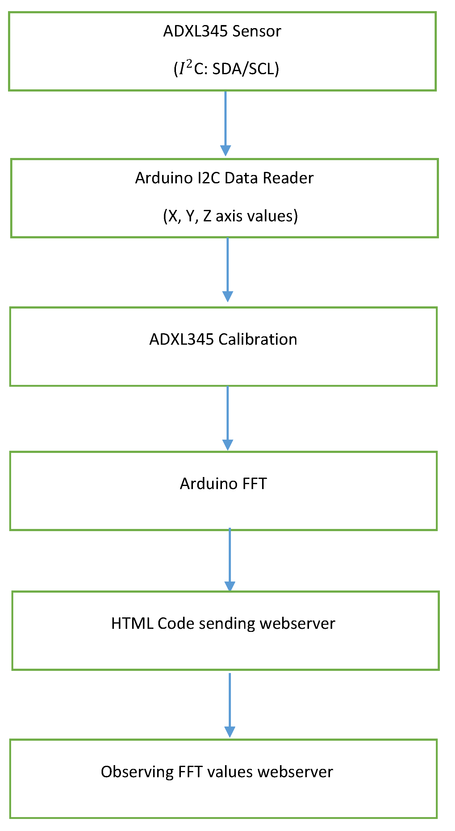
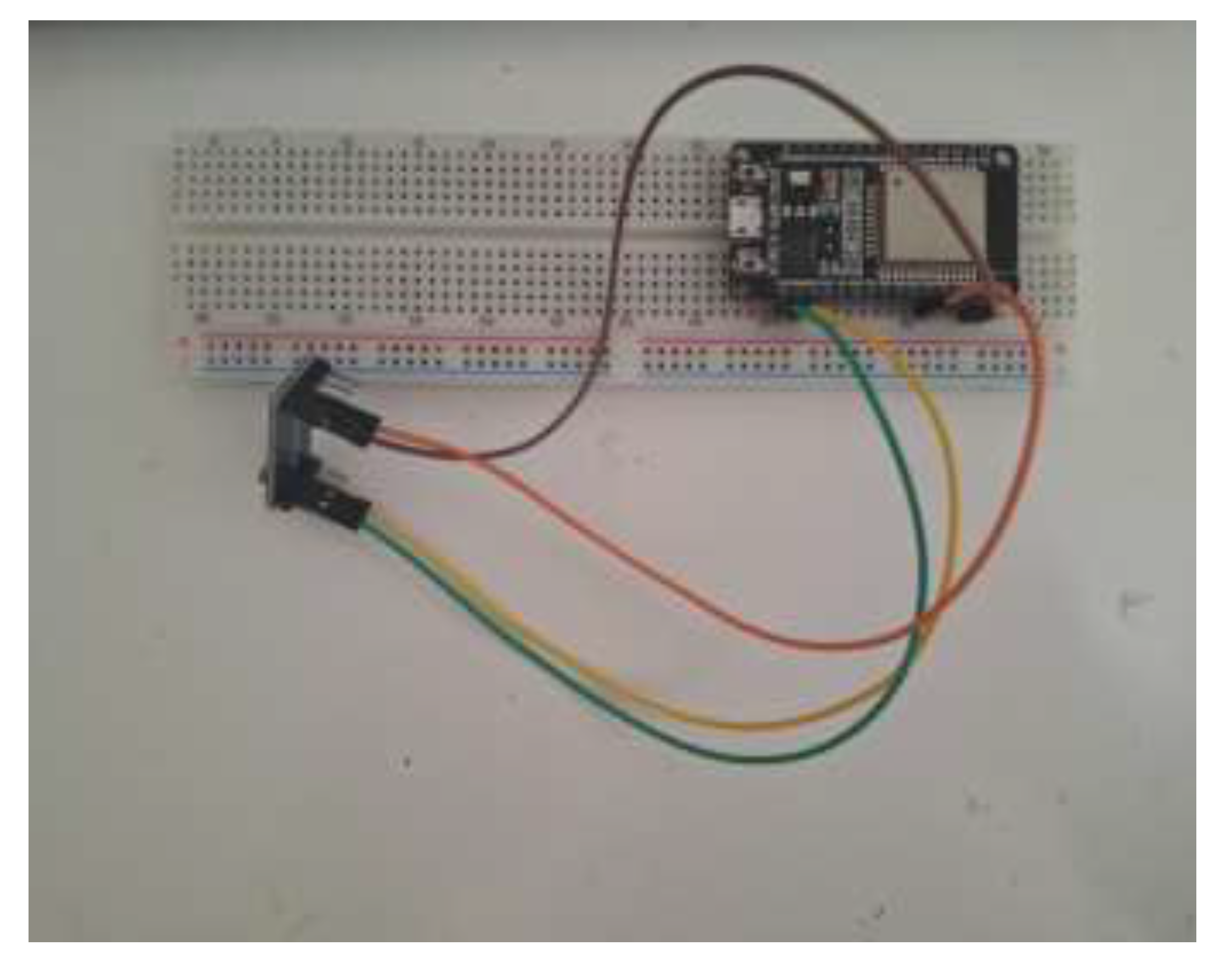
Figure 6.
(Software part).
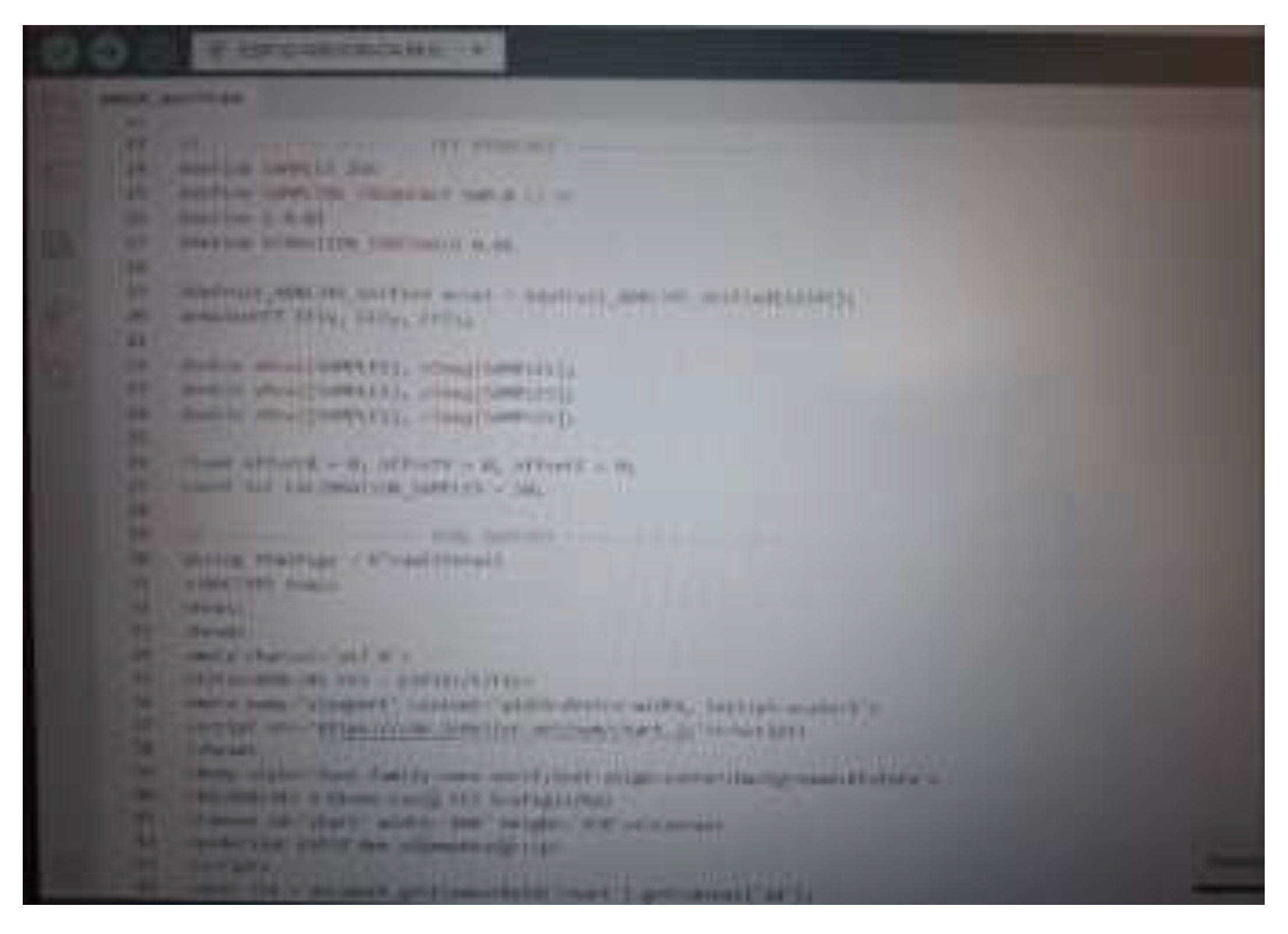
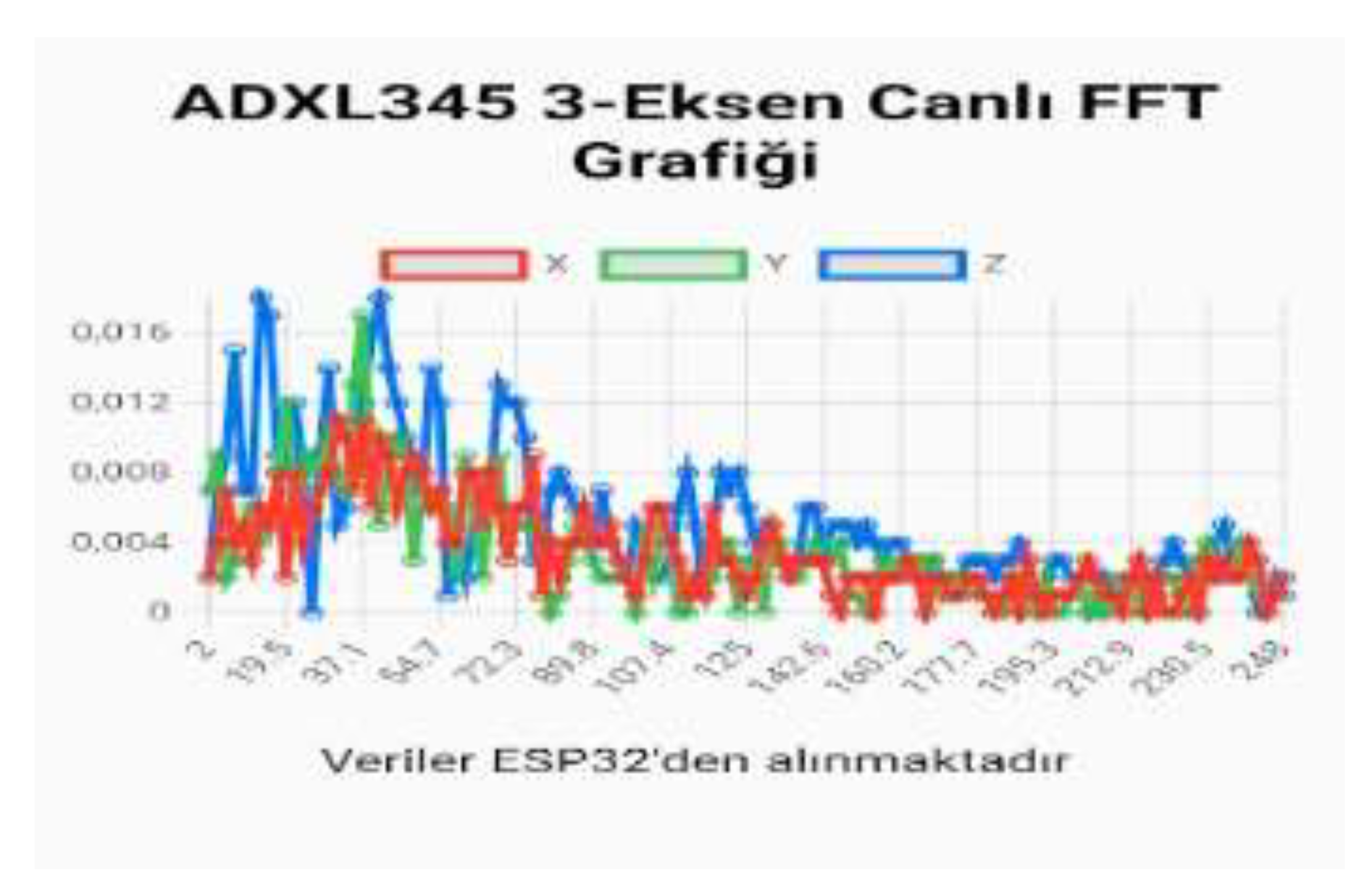
Figure 7.
(Webserver ).
VI Results and Discussion
After FFT conversion of acceleration data obtained from the ADXL345 sensor, it was observed that the amplitude of the vibration data increased as the vibration data increased. Fourier analysis has proven to be a powerful and effective tool for determining resonance frequencies in drone vibration systems.The resonance effect increased significantly when the system natural frequency coincided with the engine frequency.In structures with low damping, resonance occurred more sharply and with higher amplitude.The frequency spectrum offered a significant advantage in separating engine vibration and structural vibration modes.The obtained results provide the basis for predicting vibration problems in drone design, selecting appropriate engine and propellers, and designing filtering (notch, low-pass) in control algorithms. However, in real-world flight conditions where engine speed varies over time, FFT alone is clearly insufficient, and the inclusion of time-frequency analyses (e.g., spectrograms) is essential.In general, the Fourier-based method provided high accuracy in understanding drone vibrations and identifying resonance regions.
However, it was observed that the model had certain limitations due to linear assumptions and constant frequency motor assumption.
- ⮚
- Frequency Response
Figure 8.
Frequency Response.
- ⮚
- Time Response
Figure 9.
Time Response.
- ⮚
-
System Stability
- ●
- According to the FFT analysis:
- ●
- Main vibration frequencies are low and constant → the system is stable.
- ●
- No sudden high-frequency components → propeller vibration is under control.
- ●
- Amplitudes measured with the ADXL345 are significant, but damped behavior is observed in the system.
- ❖
- Success
- ○
- Direct vibration measurement
The ADXL345 provides real-time acceleration data in three axes (X, Y, Z).We can clearly observe propeller vibrations.
- ○
- Frequency analysis with FFTSystem frequency components can be easily determined.Main vibrations and propeller frequencies can be identified.
- ○
- Simplicity of the mass-damper model
By setting k = 0, the system differential equations are simplified and can be analyzed using the Laplace transform.A stable and understandable mathematical model is created.
- ○
- System stability analysis
Laplace domain: Damped response can be observed, and system stability can be easily checked.
- ○
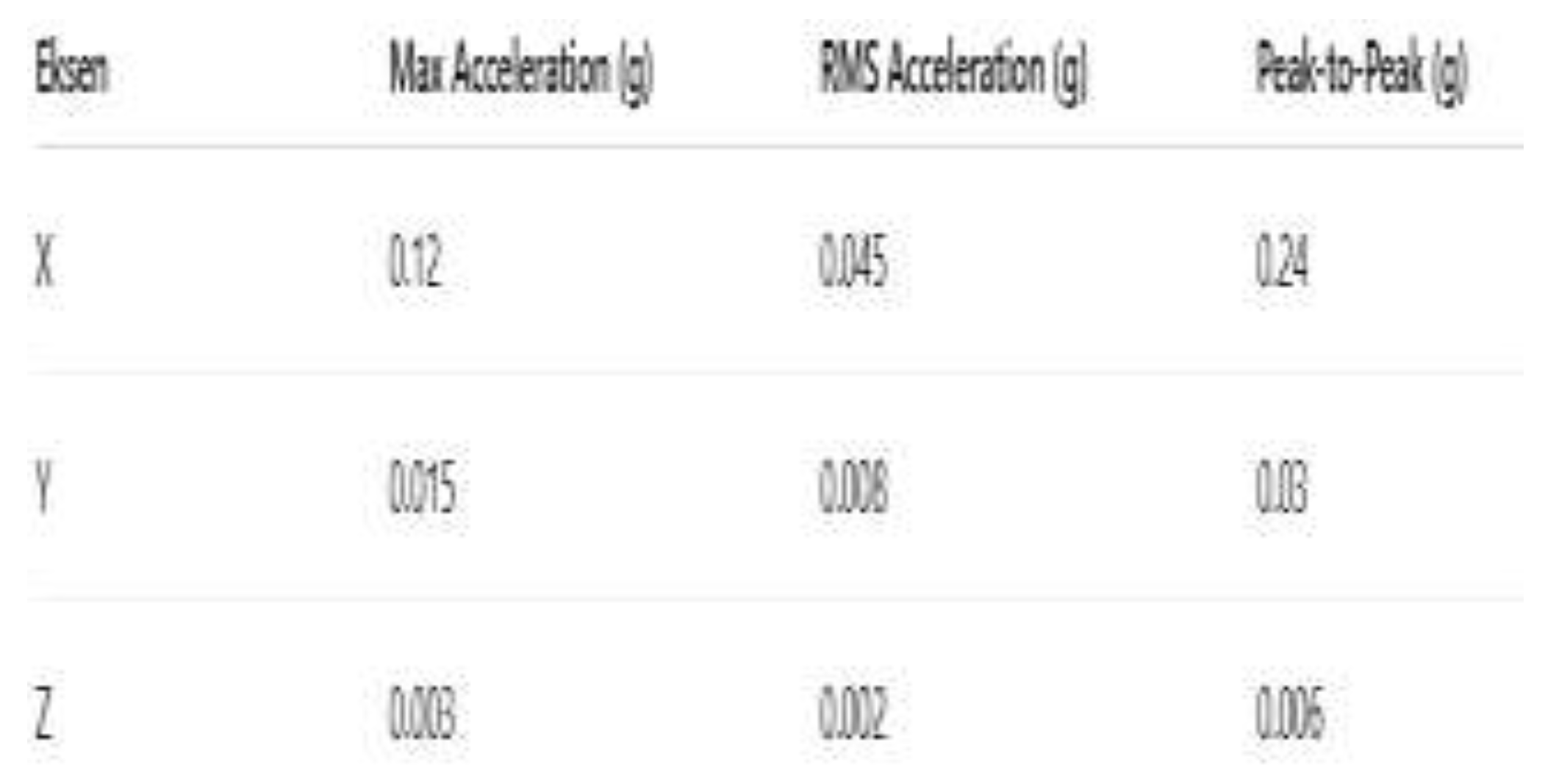
- Combining time and frequency domains
Both time and frequency responses can be obtained.Maximum, RMS, and peak-to-peak values can be calculated.
- ❖
- Limitations
- ○
- Spring effects neglected (k=0)
Elastic effects may occur in the real system.Resonance or natural frequencies cannot be observed.
- ○
- Limitations of the ADXL345 sensor
Measurement accuracy and resolution are limited (±16 g range, 10–13 bits).The signal may be affected by noise at high-frequency vibrations.
- ○
- Estimation of the damping coefficient c
The damping ratio is generally unknown and is estimated.Therefore, the time response and amplitudes may not be completely accurate.
- ○
- Data size and sampling frequency
256 samples and a sampling frequency of 500 Hz provide limited resolution.Higher frequency components or short vibration pulses may be lost.
- ○
- Multi-axis interactions neglected
The model assumes each axis is independent.
In reality, the X, Y, and Z axes may interact.
VII. Evalution and Comparison
- ⮚
- Comparison with different methods (if applicable)
Laser Doppler Vibrometer (LDV):Expensive, requires line-of-sight, limited portability[6],LDV offers higher accuracy and resolution; better for detailed frequency response and high-frequency components.Strain Gauge / Piezoelectric Sensors:Requires mechanical attachment, may affect system dynamics,Provides direct structural response; more invasive than ADXL345 but can capture higher-frequency vibration components.Optical Motion Capture:Limited temporal resolution[7], less precise for micro-vibrations,Useful for gross motion analysis; less effective for pervane micro-vibrations compared to ADXL345.
- ⮚
- Comparison with Similar Systems in the Literature
On- rotor MEMS accelerometer approaches;Lin et al.( Experimental Investigation on the Propeller Imbalance) detected propeller imbalances with a MEMS accelerometer mounted directly on the propeller/ motor mecca.This is veritably analogous to your ADXL345- grounded vibration monitoring approach a system that’s both low- cost and able of detecting real- world propeller climate.Lin’s study detected veritably small imbalances(0,25 weight difference), demonstrating the perceptivity of MEMS detector- grounded vibration monitoring systems.Calculator Onboard Accelerometer: FFT AnalysisGhamlamchi and Mueller from Berkeley used the flight computer’s onboard accelerometer FFT analysis to descry multirotor propeller damage.This system focuses on vibration- grounded fault opinion without installing fresh detectors — using the being IMU. As your model demonstrates, it can descry faults or imbalances by assaying frequence factors.Vibration Monitoring Systems with the ADXL345:Holovatyy et al. developed a system that measures vibration acceleration in real time and generates an FFT diapason using a jeer Pi and ADXL345.This demonstrates the validity of the detector- data accession- spectral analysis approach in artificial ministry monitoring.
It’s architecturally relatively analogous to your drone propeller vibration system.MEMS Sensor Reliability and Drone Fault Detection:In the study” An Investigation of the trustability of Different Types of Detectors in Real- Time Vibration- Grounded Anomaly Inspection in Drones,” the ADXL345 detector was set up to be dependable in drone vibration fault discovery.This is a strong literature base for system as well ADXL345 is a common and effective choice for real- time drone vibration monitoring and anomaly discovery.
- ⮚
- Relationship to Real-World Applications
Condition Monitoring and Fault Detection( Structural Health Monitoring)[8]:Propeller imbalance or motor failure is a critical issue in drones. Vibration- grounded systems( like your ADXL345 FFT analysis) can give real- time fault discovery.
For artificial drones( e.g., weight, husbandry, INS), similar monitoring systems reduce conservation costs and increase trustability.Balance and Performance Optimization:By measuring and assaying propeller vibration, propeller balance can be bettered. This reduces noise, increases energy effectiveness, and reduces mechanical stress caused by vibration.This is a significant performance and trustability advantage for both professional and hobbyhorse- grade drones.
Safety and preventative conservation:Vibrational analysis- grounded monitoring provides early discovery of conditions similar as propeller cracks, balance problems, or motor disunion.A preventative conservation strategy can be critical, especially in marketable and public operations( e.g., examination, weight, husbandry).
VIII. Conclusion and Future Work
- ⮚
- Overall Evaluation of the Project
As part of this project, drone propeller vibrations were measured in real time using an ADXL345 MEMS accelerometer, and frequency components were extracted using FFT.A simplified model assuming K=0 demonstrated that vibrations can be primarily determined by damping.Users can monitor the vibration spectrum in real time through a web-based graphical display.The project provides a feasible and scalable system for monitoring drone vibrations using low-cost sensors and simple algorithms.
- ⮚
- Significance of the Findings
By analyzing vibration frequencies and amplitudes, drone propeller imbalances and potential failures can be identified.Sensor data can be used for condition monitoring (SHM) and maintenance optimization.Real-time FFT analysis can improve drone flight safety and reduce maintenance costs.This study demonstrated results consistent with MEMS-based vibration monitoring systems in the literature, confirming the practicality and reliability of low-cost sensors like the ADXL345.
- ⮚
- Future Improvements and Recommendations
Application of time-frequency analysis: Since engine speed varies during flight, frequency changes can be tracked over time using STFT or wavelet analysis.Development of multi-degree-of-freedom and nonlinear models: The mode shapes and nonlinear behavior of the real drone body and propellers can be incorporated into the model.Validation with real flight data: Simulation results can be tested using IMU and engine telemetry data.Vibration-reducing control strategies: Vibration in resonance regions can be reduced with notch filters or active control methods.Motor and propeller optimization: Using resonance information, the motor-propeller-ESC combination can be optimized for performance and vibration.
Author Contributions
The areas of use of Fourier analysis and research in the literature were conducted. The software, mobile application, and technical processes of the ADXL345 sensor were developed. The general concept of the study was created, the problem was defined, and the research methodology was designed. Data collection, data analysis, report writing, and editing were performed.
Acknowledgments
We would like to thank Atılım University Electrical and Electronics Department for their support during the implementation of this study.
References
- Sönmezocak, T.; Kutay, A. Intelligent UAV health monitoring: Detecting propeller and structural faults with MEMS-based vibration. IEEE Access 2025, 13, 21401–21412. [Google Scholar] [CrossRef]
- Tadavi, R.S.V.S. Drone Stabilization Using Laplace Transform: A Classical Control Approach. ResearchGate, 2025.
- Mueller, B.G.V.M. Vibration-Based Propeller Fault Diagnosis for Multicopters. HiPeRLab, UC Berkeley, 2018.
- Kaya, D.; Kutay, A.T. Modeling and experimental identification of quadrotor aerodynamics. M.S. thesis, Middle East Technical Univ., Ankara, Turkey, 2016.
- https://mathworld.wolfram.com/FourierTransform.html.
- Castellini, P.; Martarelli, M.; Tomasini, E.P. Laser Doppler Vibrometry: Development of advanced solutions answering to technology’s needs. Mechanical Systems and Signal Processing 2006, 20, 1265–1285. [Google Scholar] [CrossRef]
- Adewuyi, S.A.; Deivasigamani, A.J.; Xu, M. Dynamic strain measurement using strain gauges and piezoelectric sensors. Journal of Sound and Vibration 2013, 332, 5984–6002. [Google Scholar]
- Rosales, J.G.; Castillo, P.A.; Rojas, E.S. Condition monitoring and structural health analysis for UAVs using vibration signatures. Aerospace Science and Technology 2021, 110, 106–120. [Google Scholar]
Disclaimer/Publisher’s Note: The statements, opinions and data contained in all publications are solely those of the individual author(s) and contributor(s) and not of MDPI and/or the editor(s). MDPI and/or the editor(s) disclaim responsibility for any injury to people or property resulting from any ideas, methods, instructions or products referred to in the content. |
© 2026 by the authors. Licensee MDPI, Basel, Switzerland. This article is an open access article distributed under the terms and conditions of the Creative Commons Attribution (CC BY) license (http://creativecommons.org/licenses/by/4.0/).
Copyright: This open access article is published under a Creative Commons CC BY 4.0 license, which permit the free download, distribution, and reuse, provided that the author and preprint are cited in any reuse.


