Submitted:
29 December 2025
Posted:
30 December 2025
You are already at the latest version
Abstract
Conventional straight microchannel heat sinks often develop progressively thicker hydrodynamic and thermal boundary layers, which elevates wall temperatures and weakens downstream cooling performance under high heat flux. This work investigates a slotted converging–diverging microchannel (S–CD) configuration that combines periodic area variation with transverse slot interruptions to repeatedly re-initiate boundary layers and intensify near-wall mixing. A three-dimensional, single-phase conjugate heat-transfer model is implemented in COMSOL Multiphysics for deionized-water cooling with uniform bottom-wall heat flux. The S–CD design is compared against a straight microchannel (S) and an unslotted converging–diverging baseline (CD) under identical envelope size and operating conditions. The simulations show that slot disturbances located in diverging segments generate localized jetting and multi-scale recirculation, suppressing persistent hot streaks and improving temperature uniformity. For the representative cases reported, the S–CD configuration reduces peak substrate temperature and overall thermal resistance relative to the CD baseline while maintaining a comparable pressure drop. A performance evaluation criterion based on heat-transfer enhancement at equal hydraulic penalty indicates a net thermohydraulic advantage of the proposed slot-assisted CD concept. The presented modeling workflow provides a practical platform for geometry optimization and design studies of compact liquid-cooled heat sinks for high-heat-flux electronics.
Keywords:
microchannel heat sink
; converging–diverging channel
; transverse slots
; conjugate heat transfer
; laminar flow
; pressure drop
; COMSOL Multiphysics
1. Introduction
Thermal constraints remain a primary limitation in compact electronic systems as chip-level heat flux and package integration continue to increase.[1,2,6,22] Liquid-cooled microchannel heat sinks offer high surface-area-to-volume ratios and short conduction paths, enabling large heat removal from small footprints.[1,3,4,9] Despite these advantages, many practical single-phase microchannel designs suffer from boundary-layer growth along the streamwise direction.[4,5] As the thermal boundary layer thickens, the local heat-transfer coefficient diminishes downstream and wall temperatures become increasingly non-uniform.[5,6]
A wide body of literature has explored passive geometric enhancements that aim to improve heat transfer without external actuation or moving parts.[9,13,14] Two recurring strategies are:
However, enhancement techniques that substantially increase mixing can also increase form losses and pumping power.[9,13] For electronics cooling, the desired design outcome is a clear reduction in peak temperature and thermal resistance with minimal hydraulic penalty.[19,20]
In this work, a slotted converging–diverging (S–CD) microchannel is investigated numerically. The design places transverse slot interruptions within the diverging segments of a CD channel. This placement is intentional: diverging segments provide geometric “room” for controlled recirculation and reattachment, and slot-induced disturbances can energize near-wall fluid precisely where deceleration and separation tendencies are strongest.[8,11] The objectives of this study are:
2. Numerical Methodology
2.1. Computational Domain and Geometries
A representative unit cell consisting of one microchannel and the surrounding solid substrate is modeled using symmetry to reduce computational cost.[3,4] The heat-sink envelope is 120 mm (length) × 40 mm (width) × mm (height). Three channel concepts are considered:
- S-MC: straight microchannel with constant cross-section,
- CD-MC: converging–diverging microchannel with periodic area variation,
- S–CD-MC: CD-MC with transverse slots placed within diverging regions.
The straight channel uses a representative hydraulic diameter of approximately mm.[4,7] The CD channel varies its width between a throat and an expanded section, while maintaining the same overall envelope and unit-cell periodicity.[8,21] In S–CD-MC, transverse slots of width mm are introduced; the slot depth is taken as half of the local channel height. Slot placement is limited to diverging segments to enhance mixing where the flow decelerates and thermal boundary layers tend to persist.[11,18]
2.2. Governing Equations
The model solves steady, three-dimensional, incompressible laminar flow with conjugate heat transfer. Radiation is neglected.[3,4] Water properties are treated as temperature-dependent (implemented through COMSOL material functions or piecewise-linear fits), which is a standard practice in microchannel simulations when wall-to-fluid temperature differences are non-negligible.[4,5]
2.2.1. Fluid Flow
Continuity
Momentum (Navier–Stokes)
2.2.2. Heat Transfer
Energy (fluid)
Energy (solid)
2.3. Boundary Conditions and Operating Conditions
Figure 4 presents the boundary-condition layout for the S–CD unit cell. The same operating conditions are applied to all cases to ensure fair comparison:
- Inlet: uniform velocity and temperature .
- Outlet: pressure outlet Pa (gauge) with convective outflow for heat transfer.
- Heated base: uniform heat flux applied to the external bottom surface of the substrate.
- External non-heated surfaces: adiabatic ().
- Fluid–solid interfaces: no-slip , and continuity of temperature and heat flux.
- Symmetry planes: symmetry (zero normal velocity and zero normal gradients).
2.4. Meshing Strategy and Grid Independence
Unstructured tetrahedral meshes with boundary-layer inflation are employed in the fluid domain to resolve near-wall velocity and thermal gradients, particularly in the CD throat regions and around the slot edges where strong shear and temperature gradients occur.[10,24] The solid domain is meshed with compatible resolution at the conjugate interface. A grid-independence study is conducted for S–CD (the most complex geometry) by monitoring peak substrate temperature and overall pressure drop . Refinement is continued until changes fall below approximately 1% in both metrics.[3,25]
2.5. Solver Settings and Numerical Verification
The steady coupled system is solved using COMSOL’s stationary solver with either a segregated approach (flow then energy) or a fully coupled approach, and a direct linear solver such as PARDISO. A relative tolerance of is enforced on dependent variables.[29] Numerical verification is performed using the straight-channel case by comparing trends in pressure drop and heat transfer against established laminar rectangular-duct references and microchannel benchmarks.[3,4,5,7,26] This step ensures that the conjugate coupling, property variations, and boundary-condition implementation behave consistently with accepted microchannel modeling practice.[5,6]
3. Results and Discussion
3.1. Flow Structure in CD and Slot-Induced Mixing in S–CD
The CD geometry is intended to periodically accelerate and decelerate the flow. Figure 8 shows a representative velocity-magnitude field in the CD-MC unit cell. In the converging section, streamwise acceleration increases wall shear and reduces local boundary-layer thickness. In the diverging section, deceleration promotes adverse pressure gradients, which can trigger separation and recirculation zones depending on the CD amplitude and Reynolds number.[8,15,23] These recirculation zones are important because they transport cooler core fluid toward the heated walls and can periodically renew near-wall fluid, thereby improving heat transfer compared to straight channels.[6,8]
In the S–CD design, transverse slots provide additional, controlled disturbances specifically within diverging regions. Figure 9 highlights the resulting flow structure. Each slot introduces a localized disruption that behaves like a micro-jet and generates compact vortical structures near the slot edges.[10,11] Instead of relying only on large-scale recirculation driven by CD expansion, the S–CD design creates repeated, distributed mixing events. This leads to (i) repeated re-initiation of near-wall momentum and thermal boundary layers downstream of each slot and (ii) more uniform replenishment of cooler fluid at the heated wall.[17,18] Such mechanisms are consistent with interrupted microchannel concepts that enhance heat transfer by repeatedly resetting boundary layers.[10,11,12]
A practical interpretation of Figure 8Figure 9 is that the CD geometry primarily creates periodic large-scale mixing associated with expansion and reattachment, while the S–CD concept adds repeated localized disturbances that increase the frequency of boundary-layer redevelopment.[8,11] This “high-frequency” renewal is particularly beneficial in laminar regimes where turbulent mixing is absent.[5,6]
3.2. Pressure Drop Characteristics and Hydraulic Penalty
Pressure loss is a key constraint in liquid-cooled microchannel heat sinks because pumping power scales with at fixed flow rate.[1,2] Figure 10 shows the pressure field for CD-MC. The pressure oscillates within each unit cell due to periodic acceleration and deceleration. The sharpest pressure gradients occur near the throat where velocities are highest, and partial recovery occurs in diverging regions where velocities decrease.[8,15]
Figure 11 shows that S–CD-MC introduces additional localized pressure drops at the slot locations, as expected for sudden geometric interruptions.[10,18] Importantly, the overall pressure-drop increase is not necessarily proportional to the number of disturbances. In many interrupted-channel designs, localized form losses can be partially offset by reducing extended separation zones and weakening persistent adverse pressure gradients in the diverging section.[10,12,17] In the present simulations, the net pressure drop remains comparable between CD and S–CD for the representative case, indicating that the added disturbances deliver thermal benefit without a large additional hydraulic penalty.[9,13]
3.3. Temperature Field, Hot-Spot Mitigation, and Thermal Uniformity
Figure 12 and Figure 13 compare heated-wall temperature distributions for CD-MC and S–CD-MC. In the CD case (Fig. Figure 12), the periodic redevelopment reduces peak temperature compared with a straight channel, but elongated warm regions can still persist downstream because the boundary layer can regrow between redevelopment zones.[6,8]
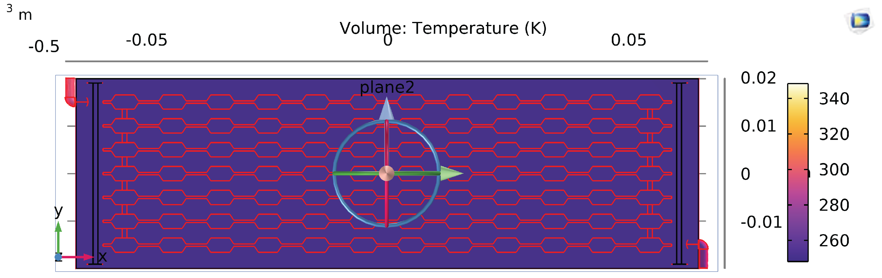
In the S–CD case (Fig. Figure 13), the temperature field becomes more spatially uniform. Slot-induced disturbances repeatedly re-initiate the thermal boundary layer and interrupt the formation of long, streamwise hot streaks. The resulting hot spots are smaller and more distributed, which is favorable from a reliability standpoint because it reduces localized thermal stress and peak junction temperature sensitivity.[17,19,20]
For the representative operating point (, , ), the peak substrate temperatures are:
- S-MC: K,
- CD-MC: K,
- S–CD-MC: K.
3.4. Thermal Resistance and Performance Evaluation Criterion
The overall thermal resistance is defined using the total imposed heat rate
Here is the heated base area associated with the modeled domain. For convenience (and to maintain consistency with the representative values reported), if the full envelope base area is taken as and , then . Using Eq. (6):
The reduction in for S–CD relative to CD reflects that the same heat load is removed with a lower peak temperature, consistent with the improved temperature uniformity seen in Fig. Figure 13.[17,20]
To compare thermohydraulic performance at comparable hydraulic penalty, a commonly used performance evaluation criterion (PEC) is adopted for enhanced channels:[13,28]
where is the average Nusselt number and is the Fanning friction factor averaged over a unit cell or over the full channel length. Values above unity indicate a net advantage in heat transfer relative to the increase in hydraulic losses.[2,28]
For the representative case, using and :
indicating that the heat-transfer gain outweighs the modest friction-factor increase. This aligns with the flow-field interpretation: S–CD introduces multiple localized mixing events that raise effectively, while the overall pressure drop remains close to the CD baseline because slot disturbances alter the separation/reattachment pattern rather than simply adding uniform viscous drag.[9,10,17]
Figure 14, Figure 15 and Figure 16 summarize peak temperature, pressure drop, and thermal resistance across designs.

Table 1.
Summary of key thermal–hydraulic metrics for S-MC, CD-MC and S–CD-MC (representative operating point).
Table 1.
Summary of key thermal–hydraulic metrics for S-MC, CD-MC and S–CD-MC (representative operating point).
| Metric | S-MC | CD-MC | S–CD-MC |
|---|---|---|---|
| Peak temperature (K) | 358.4 | 340.1 | 332.9 |
| Thermal resistance (K/W) | higher | ||
| Pressure drop (kPa) | higher | 6.93 | 6.91 |
| reduction vs S-MC (%) | – | 18 | 31 |
| reduction vs CD-MC (%) | – | – | 21.4 |
| PEC (vs CD-MC) | – | 1.00 | |
| Dominant mechanism | developing BL | CD redevelopment | slot-driven re-initiation |
4. Conclusion
A three-dimensional, single-phase conjugate heat-transfer framework was developed in COMSOL to compare straight, converging–diverging, and slotted converging–diverging microchannel heat-sink designs under identical inlet and heat-flux conditions.[3,4] The proposed S–CD concept places transverse slot disturbances within diverging segments of a CD microchannel to increase the frequency of boundary-layer redevelopment and intensify near-wall mixing.[10,11] The simulated flow fields show that slot locations act as localized disturbance sites that generate compact vortices and jet-like redistribution, limiting the streamwise growth of thermal boundary layers. As a result, the heated-wall temperature field becomes more uniform and peak temperature is reduced.[17,18]
References
- Tuckerman, D. B.; Pease, R. F. W. High-performance heat sinking for VLSI. IEEE Electron Device Letters 1981, vol. 2(no. 5), 126–129. [Google Scholar] [CrossRef]
- Kandlikar, S. G.; Grande, W. J. Evolution of microchannel flow passages—thermohydraulic performance and fabrication technology. Heat Transfer Engineering 2003, vol. 24(no. 1), 3–17. [Google Scholar] [CrossRef]
- Fedorov, A. G.; Viskanta, R. Three-dimensional conjugate heat transfer in the microchannel heat sink for electronic packaging. International Journal of Heat and Mass Transfer 2000, vol. 43(no. 3), 399–415. [Google Scholar] [CrossRef]
- Qu, W.; Mudawar, I. Experimental and numerical study of pressure drop and heat transfer in a single-phase micro-channel heat sink. International Journal of Heat and Mass Transfer 2002, vol. 45(no. 12), 2549–2565. [Google Scholar] [CrossRef]
- Morini, G. L. Single-phase convective heat transfer in microchannels: a review of experimental results. International Journal of Thermal Sciences 2004, vol. 43(no. 7), 631–651. [Google Scholar] [CrossRef]
- Datta, A.; Sanyal, D.; Agrawal, A.; Das, A. K. A review of liquid flow and heat transfer in microchannels with emphasis to electronic cooling. Sādhanā 2019, vol. 44, art. 234. [Google Scholar] [CrossRef]
- Shah, R. K.; London, A. L. Laminar Flow Forced Convection in Ducts; Academic Press, 1978. [Google Scholar]
- Yong, Y.; Teo, C. J. Mixing and heat transfer enhancement in microchannels containing converging–diverging passages. Journal of Heat Transfer 2014, vol. 136(no. 4), 041704. [Google Scholar] [CrossRef]
- Naqiuddin, N. H.; Saidur, B.; Rashid, M. A. A. A.; Azad, M. A. A. K.; Wahiduzzaman, A.; Ali, A. A. A. Overview of micro-channel design for high heat flux application. Renewable and Sustainable Energy Reviews 2018, vol. 82, 901–914. [Google Scholar] [CrossRef]
- Chai, L.; Xia, G. D.; Zhou, M. Z.; Li, J.; Qi, J. Optimum thermal design of interrupted microchannel heat sink with rectangular ribs in the transverse microchambers. Applied Thermal Engineering 2013, vol. 51(no. 1–2), 880–889. [Google Scholar] [CrossRef]
- Chai, L.; Xia, G. D.; Wang, H. S. Laminar flow and heat transfer characteristics of interrupted microchannel heat sink with ribs in the transverse microchambers. International Journal of Thermal Sciences 2016, vol. 110, 1–11. [Google Scholar] [CrossRef]
- Kamal, H.; Alim, M. A.; Bhuiyan, M. A. S. K. Analysis of interrupted rectangular microchannel heat sink. Journal of Applied Fluid Mechanics 2017, vol. 10(no. 3), 915–927. [Google Scholar] [CrossRef]
- Dewan, A.; Mahanta, P.; Raju, K. S.; Kumar, P. A review of heat transfer enhancement through flow disruption techniques in microchannels. Frontiers of Mechanical Engineering 2015, vol. 10, 372–400. [Google Scholar] [CrossRef]
- Bhandari, P.; Rawat, K. S.; Prajapati, Y. K.; Padalia, D.; Ranakoti, L.; Singh, T. A review on design alteration in microchannel heat sink for augmented thermohydraulic performance. Case Studies in Thermal Engineering 2024, vol. 50, 103795. [Google Scholar] [CrossRef]
- Chakraborty, S. Enhancement of mixing in microchannels using periodic variation of cross-section. Physics of Fluids 2007, vol. 19(no. 8), 083601. [Google Scholar] [CrossRef]
- Anwar, K.; Rahman, M. M.; Saidur, R. Influence of inlet configurations on thermal-hydraulic performance of microchannel heat sinks. International Communications in Heat and Mass Transfer 2013, vol. 43, 12–19. [Google Scholar] [CrossRef]
- Xia, G. D.; Chai, L.; Zhou, M. Z.; Wang, H. S.; Li, J. Thermal-hydraulic performance of interrupted microchannel heat sink with ribs in transverse microchambers. Heat Transfer Engineering 2017, vol. 38(no. 9), 897–906. [Google Scholar] [CrossRef]
- Ma, D.; Li, Y.; Li, Y.; Liu, W. Thermal performance of microchannel heat sink with interrupted and staggered ribs. International Journal of Heat and Mass Transfer 2016, vol. 97, 478–489. [Google Scholar] [CrossRef]
- Hung, T. C.; Ferng, Y. M.; Pei, W. C. Effects of non-uniform heat flux on cooling performance of micro-channel heat sinks. International Communications in Heat and Mass Transfer 2009, vol. 36(no. 3), 236–241. [Google Scholar] [CrossRef]
- Zhang, L.; Li, Y.; Xie, H.; Li, Y. Overview of heat transfer enhancement in microchannel heat sinks for electronic cooling. Renewable and Sustainable Energy Reviews 2017, vol. 69, 14–28. [Google Scholar] [CrossRef]
- Chen, J.; Wang, X.; Li, Z. Optimization of converging and diverging microchannel heat sink for electronic chip cooling. IEEE Transactions on Components, Packaging and Manufacturing Technology 2020, vol. 10(no. 7), 1124–1133. [Google Scholar] [CrossRef]
- Bhavnani, S. H.; Cherepanov, D. C.; Laursen, T. H. A review of single-phase convective heat transfer in microchannels. Journal of Electronic Packaging 2011, vol. 133(no. 4), 040802. [Google Scholar] [CrossRef]
- Hetsroni, G.; Mosyak, A.; Poleg, E.; Segal, Z. Heat transfer and pressure drop in micro-channels. International Journal of Heat and Mass Transfer vol. 48(no. 10), 1982–1998, 2005. [CrossRef]
- Govindarajan, P.; Kandlikar, S. Numerical study of flow maldistribution in parallel microchannel systems. International Journal of Thermal Sciences 2016, vol. 109, 230–244. [Google Scholar] [CrossRef]
- Bell, I. H.; Wehrmann, J. A.; Thome, J. R. A new model for developing flow boiling in microchannels. International Journal of Multiphase Flow 2008, vol. 34(no. 8), 689–703. [Google Scholar] [CrossRef]
- Lee, P. S.; Garimella, S. V. Thermally developing flow and heat transfer in rectangular microchannels. Journal of Heat Transfer 2005, vol. 127(no. 7), 731–739. [Google Scholar] [CrossRef]
- Hetsroni, G.; Mosyak, A.; Segal, Z.; Hashizume, D. Nonuniform temperature distribution in micro-channels. International Journal of Heat and Mass Transfer 2003, vol. 46(no. 22), 4119–4131. [Google Scholar] [CrossRef]
- Webb, R. L.; Kim, N. Principles of enhanced heat transfer, 2nd ed.; Taylor & Francis, 2005. [Google Scholar]
- COMSOL AB. COMSOL Multiphysics Reference Manual, Version 6.0; Stockholm, Sweden, 2022. [Google Scholar]
- Incropera, F. P.; DeWitt, D. P.; Bergman, T. L.; Lavine, A. S. Fundamentals of Heat and Mass Transfer, 7th ed.; Wiley, 2011. [Google Scholar]
- Kundu, P. K.; Cohen, I. M. Fluid Mechanics, 5th ed.; Academic Press, 2015. [Google Scholar]
- Bapat, A. V.; Garimella, S. V. Thermal performance of high aspect ratio microchannels in air. Journal of Heat Transfer 2007, vol. 129(no. 11), 1504–1515. [Google Scholar] [CrossRef]
- Saisorn, S.; Wongwises, M. Nanoscale effects on flow boiling heat transfer in micro-channels. Experimental Thermal and Fluid Science 2012, vol. 39, 1–7. [Google Scholar] [CrossRef]
- Sui, Y.; Teo, C. J.; Chew, P. Fluid flow and heat transfer in wavy microchannels. International Journal of Heat and Mass Transfer 2010, vol. 53(no. 13–14), 2760–2772. [Google Scholar] [CrossRef]
- Fan, Y.; Wang, L.; Chen, J. Laminar convective heat transfer in microchannels with streamwise-periodic disturbances. International Journal of Heat and Mass Transfer 2010, vol. 53(no. 7–8), 1637–1646. [Google Scholar] [CrossRef]
- Kim, S. M.; Mudawar, I. Review of databases and predictive methods for heat transfer in condensing and boiling mini/micro-channel flows. International Journal of Heat and Mass Transfer 2012, vol. 55(no. 23–24), 5749–5765. [Google Scholar] [CrossRef]
- Singh, P. K.; Chauhan, V. S. Thermal performance of inline and staggered pin fin microchannel heat sinks. International Journal of Thermal Sciences 2010, vol. 49(no. 8), 1555–1564. [Google Scholar] [CrossRef]
- Kandlikar, S. G. History, advances, and challenges in liquid flow and flow boiling heat transfer in microchannels: A critical review. Journal of Heat Transfer 2012, vol. 134(no. 3), 034001. [Google Scholar] [CrossRef]
Figure 1.
Straight microchannel (S-MC) unit-cell geometry with solid substrate and coolant domain for conjugate heat transfer.
Figure 1.
Straight microchannel (S-MC) unit-cell geometry with solid substrate and coolant domain for conjugate heat transfer.
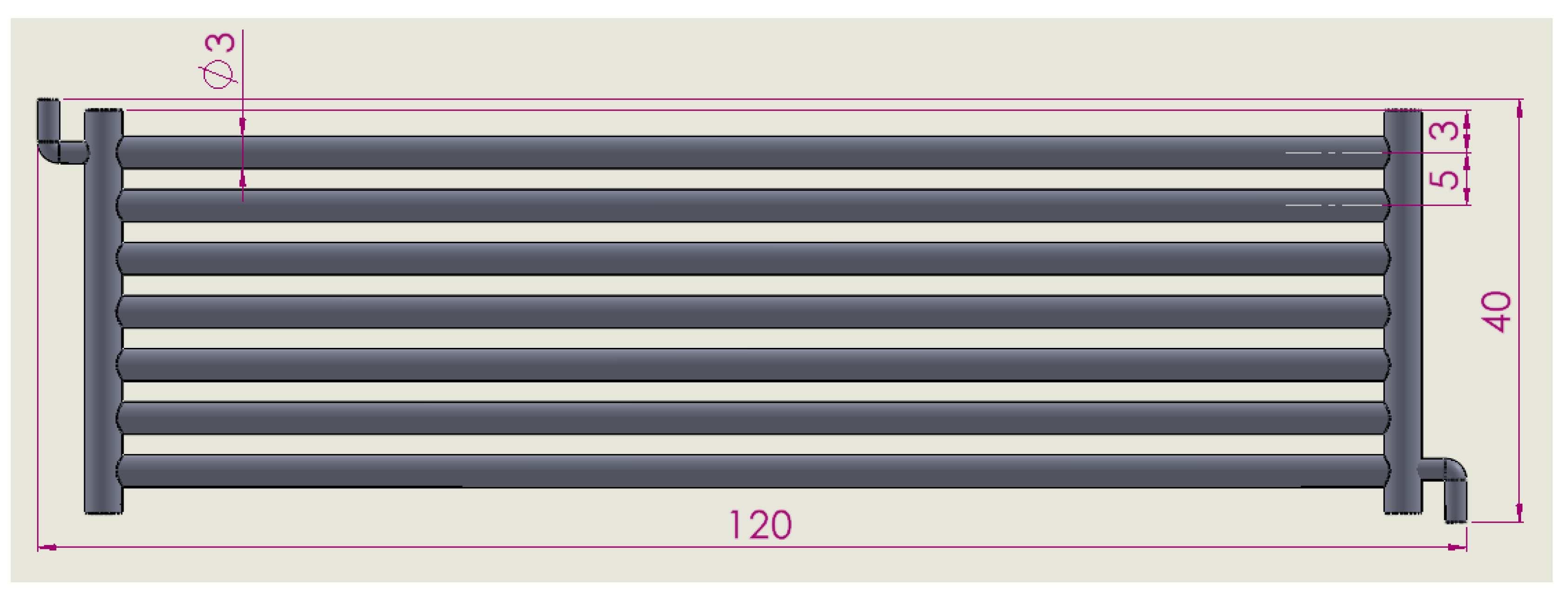
Figure 2.
Converging–diverging microchannel (CD-MC) unit-cell geometry. Periodic area variation induces repeated acceleration and deceleration along the streamwise direction.
Figure 2.
Converging–diverging microchannel (CD-MC) unit-cell geometry. Periodic area variation induces repeated acceleration and deceleration along the streamwise direction.
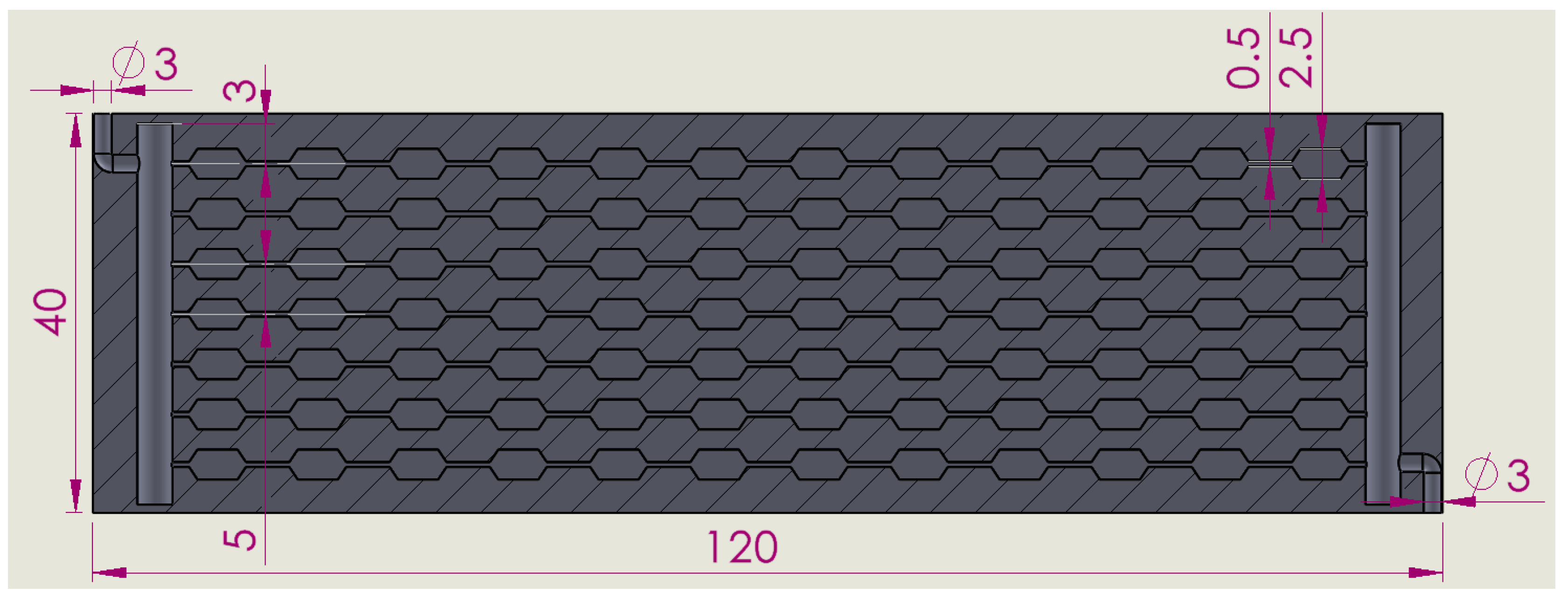
Figure 3.
Slotted converging–diverging microchannel (S–CD-MC) geometry. Transverse slots are integrated within diverging segments to interrupt boundary layers and promote near-wall mixing.
Figure 3.
Slotted converging–diverging microchannel (S–CD-MC) geometry. Transverse slots are integrated within diverging segments to interrupt boundary layers and promote near-wall mixing.
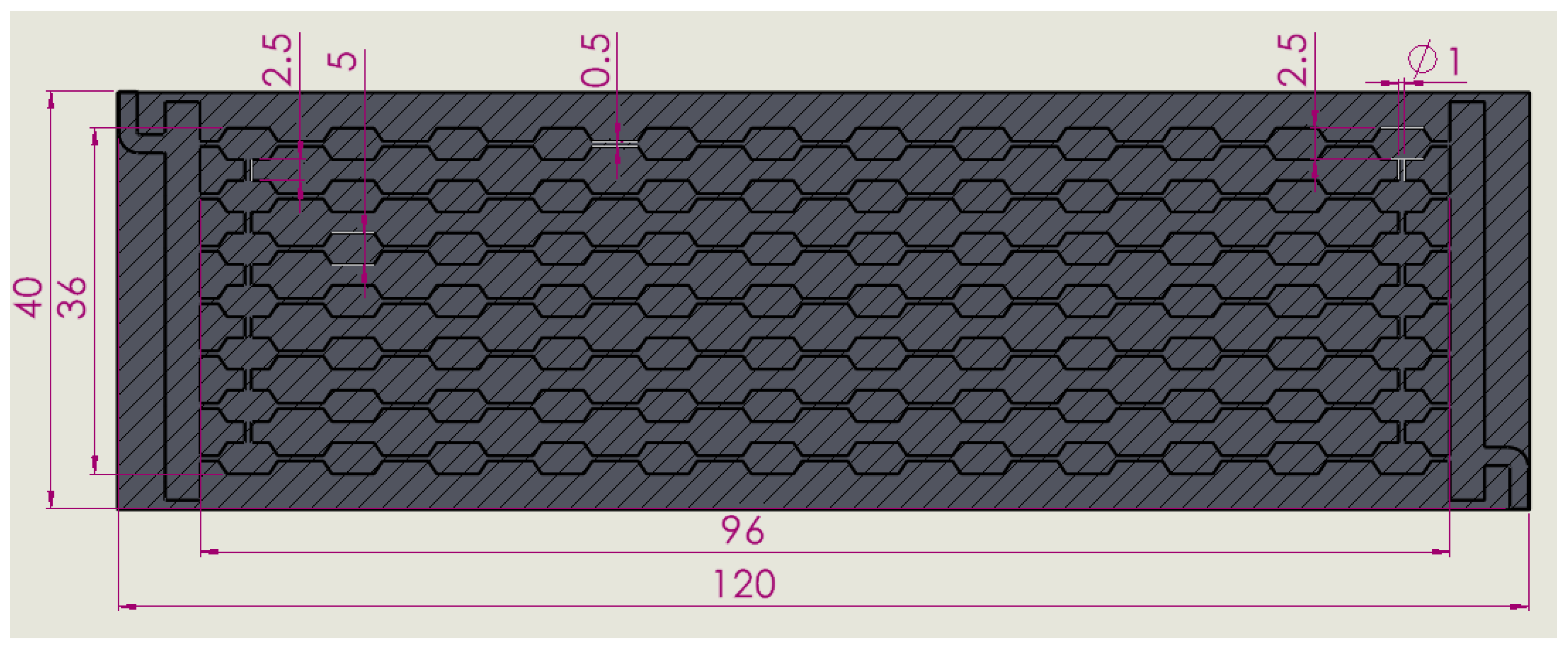
Figure 4.
Boundary conditions for the S–CD unit cell: inlet velocity and temperature, outlet pressure, uniform heat flux at the substrate base, adiabatic external walls, and symmetry planes.
Figure 4.
Boundary conditions for the S–CD unit cell: inlet velocity and temperature, outlet pressure, uniform heat flux at the substrate base, adiabatic external walls, and symmetry planes.
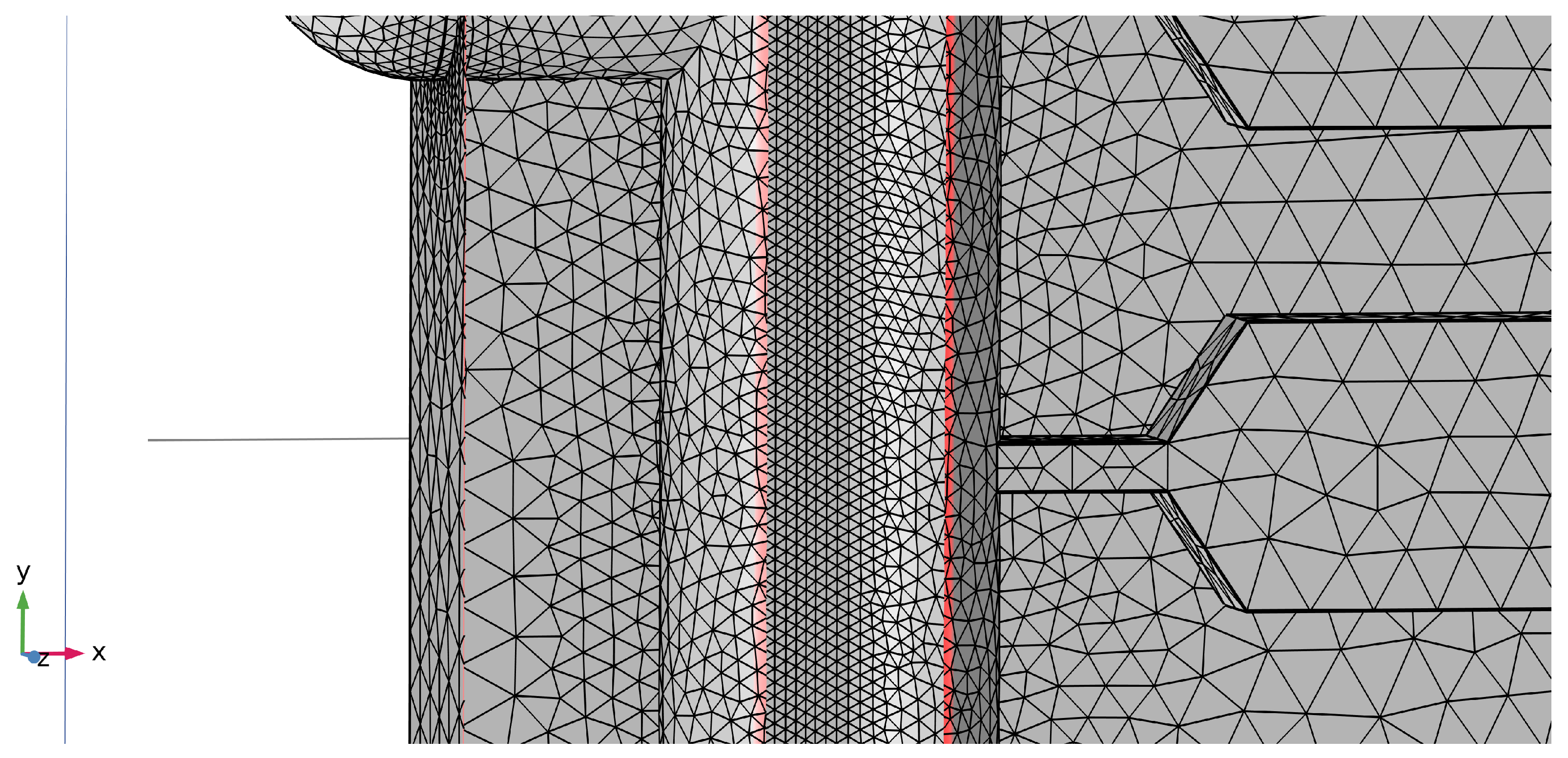
Figure 5.
Representative coarse mesh for the microchannel unit-cell domain. Coarse meshes are useful for rapid iteration and early design screening, but may under-resolve gradients near slot edges and throats.
Figure 5.
Representative coarse mesh for the microchannel unit-cell domain. Coarse meshes are useful for rapid iteration and early design screening, but may under-resolve gradients near slot edges and throats.
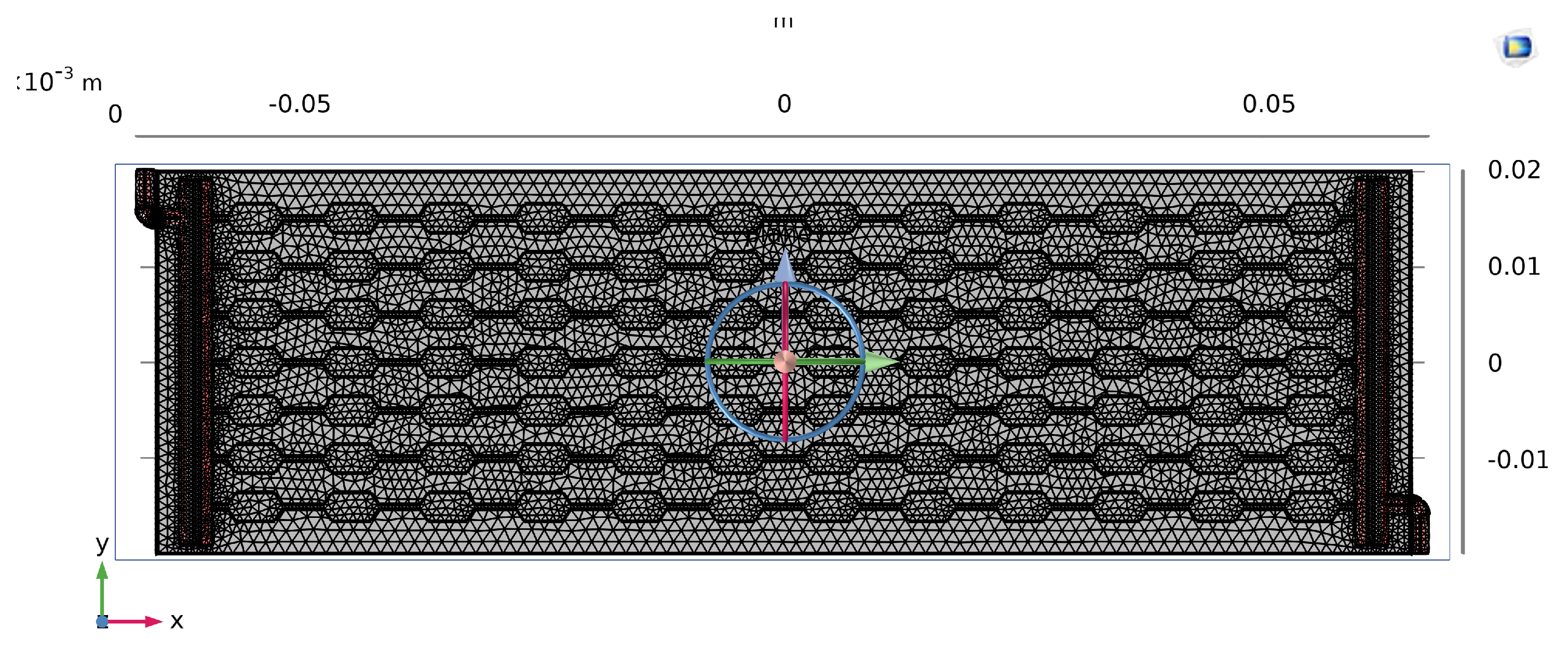
Figure 6.
Representative medium mesh used for grid-independence testing. Mesh refinement is concentrated at fluid–solid interfaces and in regions of expected flow separation or reattachment.
Figure 6.
Representative medium mesh used for grid-independence testing. Mesh refinement is concentrated at fluid–solid interfaces and in regions of expected flow separation or reattachment.
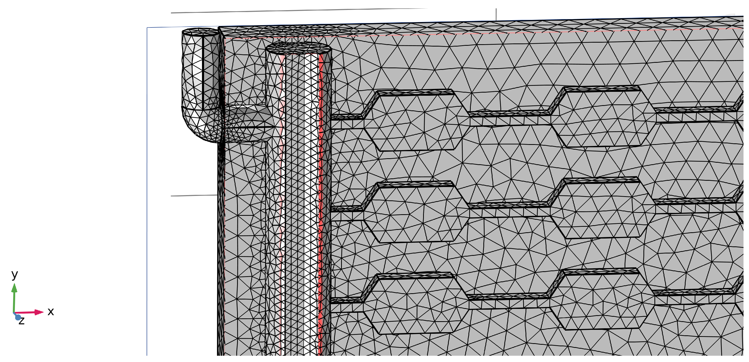
Figure 7.
Representative fine mesh for the S–CD geometry used in the final simulations. Boundary-layer elements improve resolution of wall shear and thermal gradients, which are critical for accurate prediction of and .
Figure 7.
Representative fine mesh for the S–CD geometry used in the final simulations. Boundary-layer elements improve resolution of wall shear and thermal gradients, which are critical for accurate prediction of and .
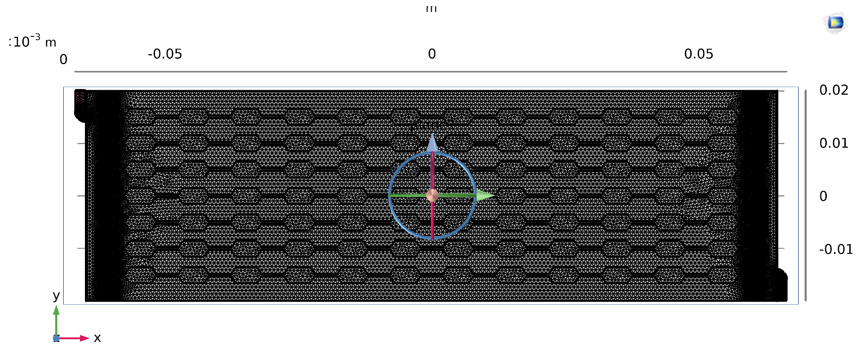
Figure 8.
Velocity field in CD-MC (unit cell). Flow accelerates through the throat and decelerates in the diverging segment, producing recirculation that enhances cross-stream transport and periodic redevelopment of boundary layers.
Figure 8.
Velocity field in CD-MC (unit cell). Flow accelerates through the throat and decelerates in the diverging segment, producing recirculation that enhances cross-stream transport and periodic redevelopment of boundary layers.
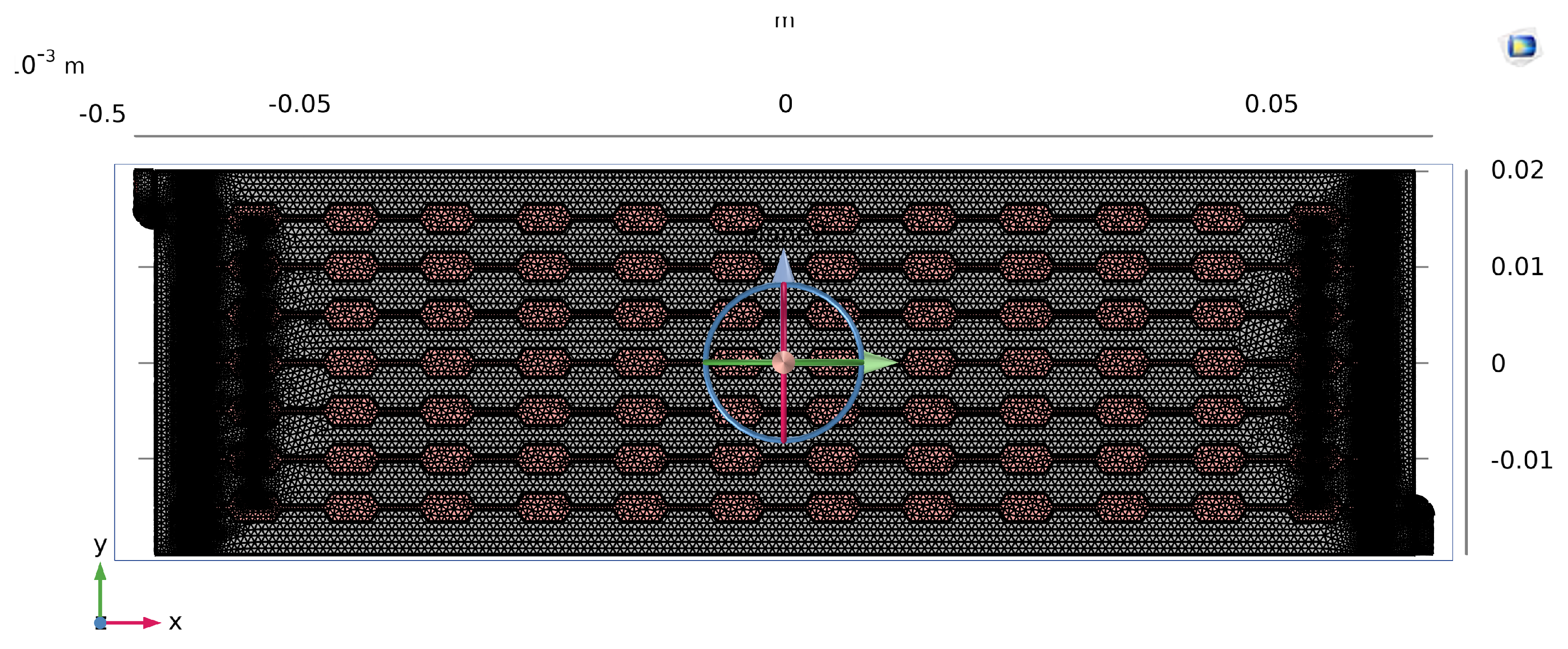
Figure 9.
Velocity field in S–CD-MC. Slot disturbances generate localized jets and multi-scale vortices, repeatedly refreshing near-wall fluid and limiting the streamwise growth of boundary layers.
Figure 9.
Velocity field in S–CD-MC. Slot disturbances generate localized jets and multi-scale vortices, repeatedly refreshing near-wall fluid and limiting the streamwise growth of boundary layers.
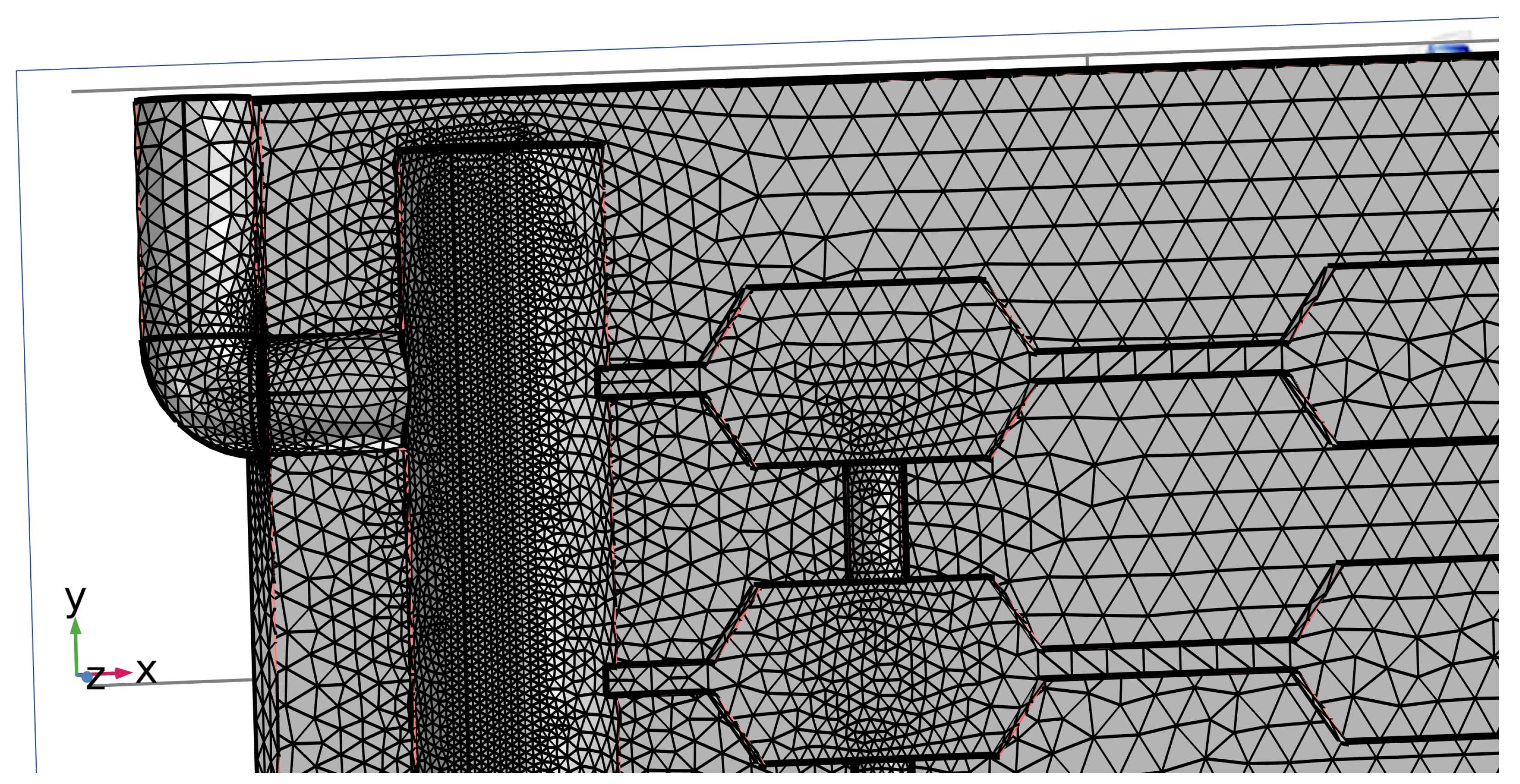
Figure 10.
Pressure field in CD-MC (unit cell), illustrating periodic pressure variation across converging and diverging sections associated with repeated acceleration/deceleration.
Figure 10.
Pressure field in CD-MC (unit cell), illustrating periodic pressure variation across converging and diverging sections associated with repeated acceleration/deceleration.
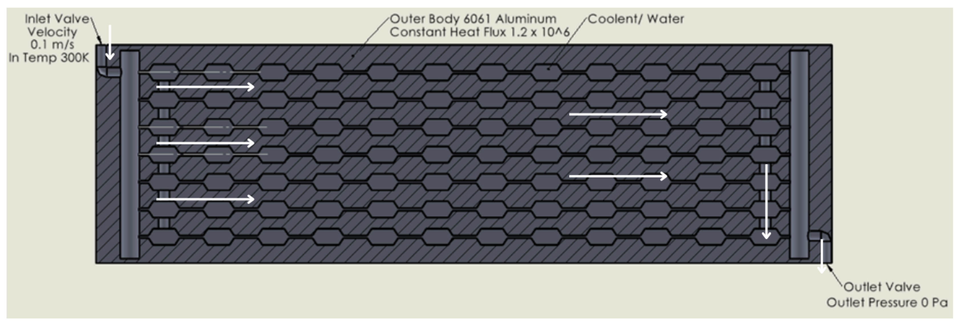
Figure 11.
Pressure field in S–CD-MC (unit cell). Localized pressure drops occur at transverse slot locations, reflecting added form losses; however, overall remains comparable to CD in the representative operating point due to altered separation/reattachment behavior.
Figure 11.
Pressure field in S–CD-MC (unit cell). Localized pressure drops occur at transverse slot locations, reflecting added form losses; however, overall remains comparable to CD in the representative operating point due to altered separation/reattachment behavior.
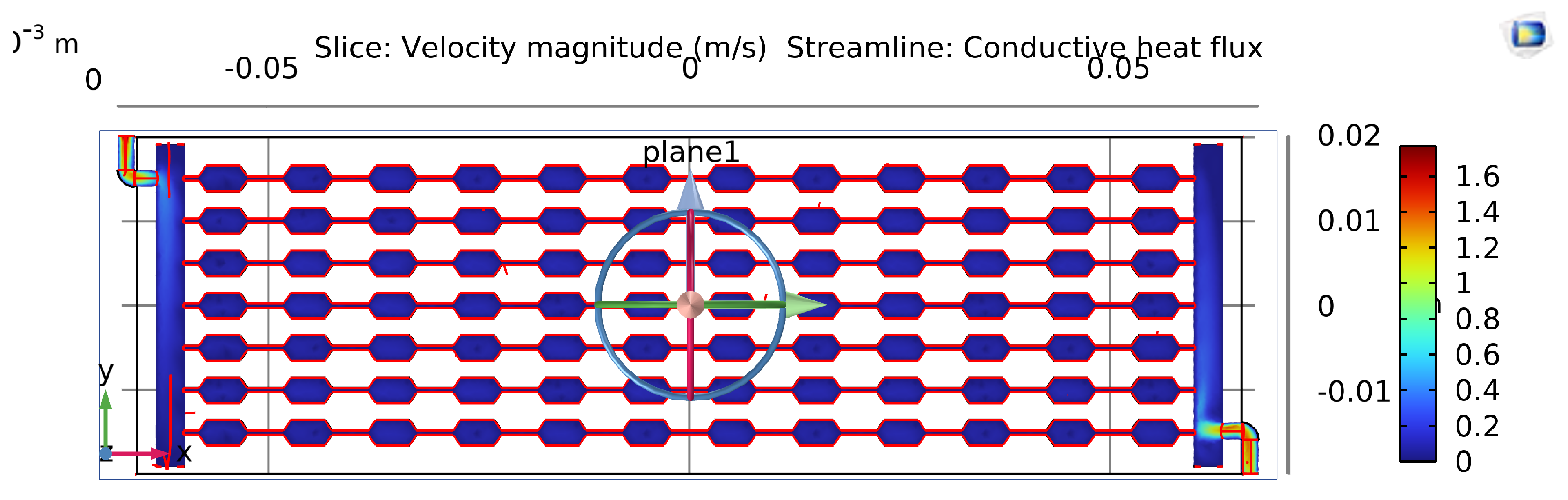
Figure 12.
Heated-wall temperature distribution for CD-MC. Periodic redevelopment improves cooling relative to a straight channel, but downstream boundary-layer growth can still produce persistent warm streaks between throats.
Figure 12.
Heated-wall temperature distribution for CD-MC. Periodic redevelopment improves cooling relative to a straight channel, but downstream boundary-layer growth can still produce persistent warm streaks between throats.
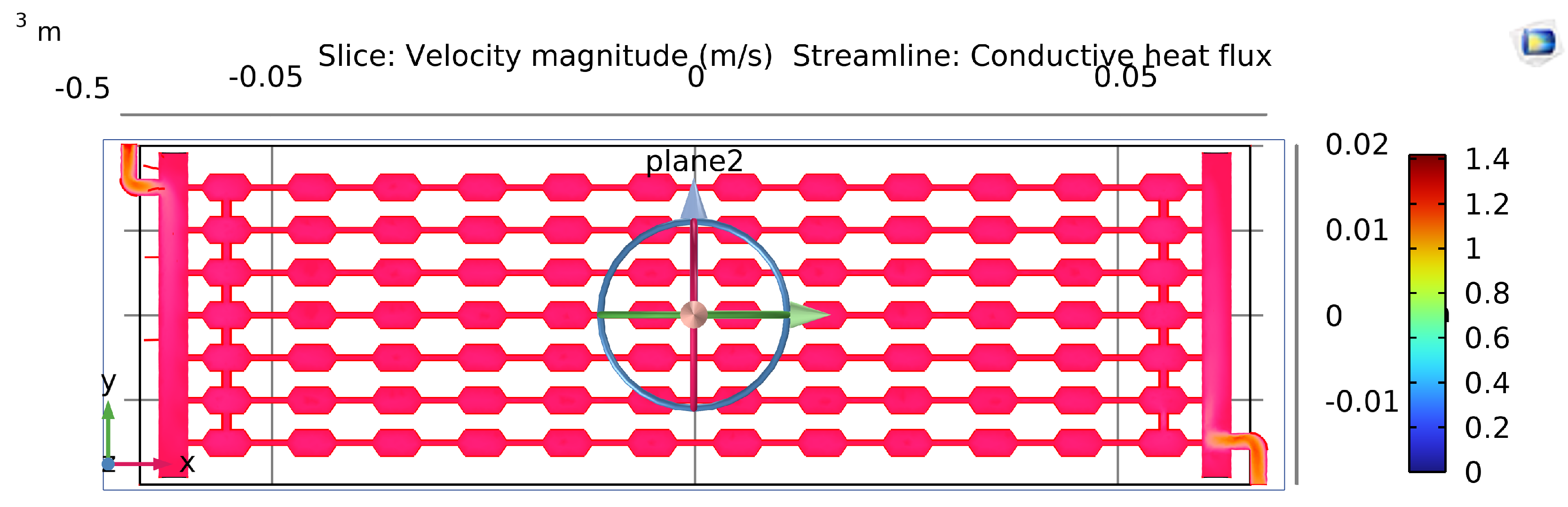
Figure 13.
Heated-wall temperature distribution for S–CD-MC. Transverse slot disturbances suppress elongated hot streaks by repeated boundary-layer re-initiation, producing lower peak temperature and improved temperature uniformity.
Figure 13.
Heated-wall temperature distribution for S–CD-MC. Transverse slot disturbances suppress elongated hot streaks by repeated boundary-layer re-initiation, producing lower peak temperature and improved temperature uniformity.
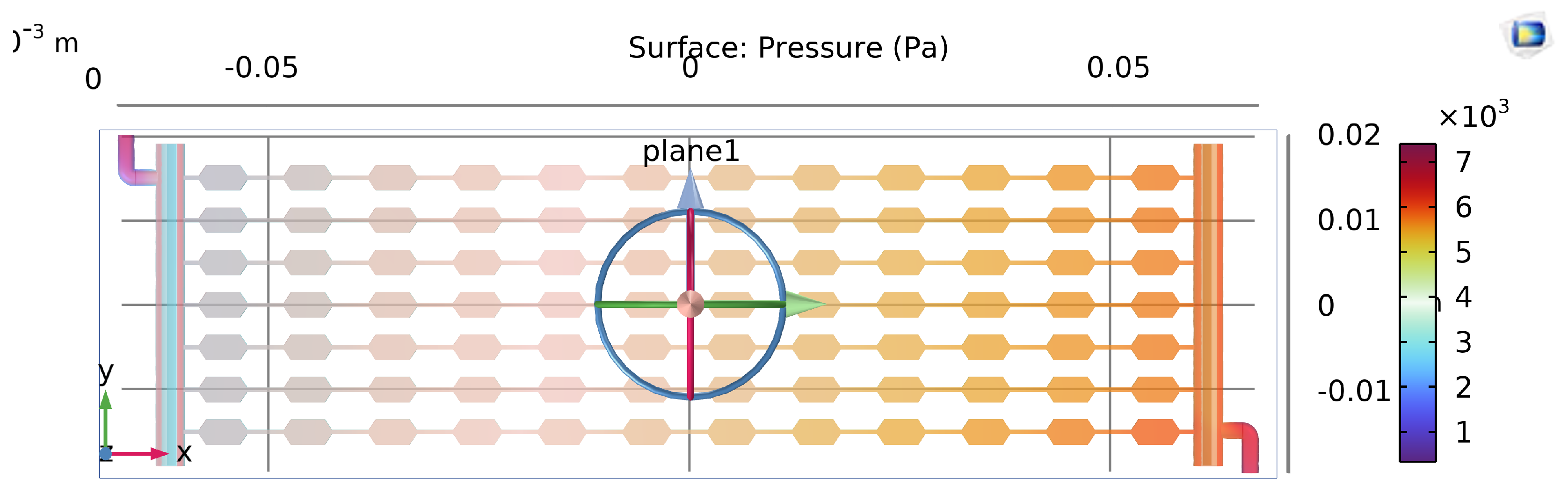
Figure 14.
Comparison of peak substrate temperature for S-MC, CD-MC, and S–CD-MC under the same heat flux and inlet conditions. The S–CD geometry exhibits the lowest peak temperature, consistent with repeated slot-induced boundary-layer re-initiation.
Figure 14.
Comparison of peak substrate temperature for S-MC, CD-MC, and S–CD-MC under the same heat flux and inlet conditions. The S–CD geometry exhibits the lowest peak temperature, consistent with repeated slot-induced boundary-layer re-initiation.
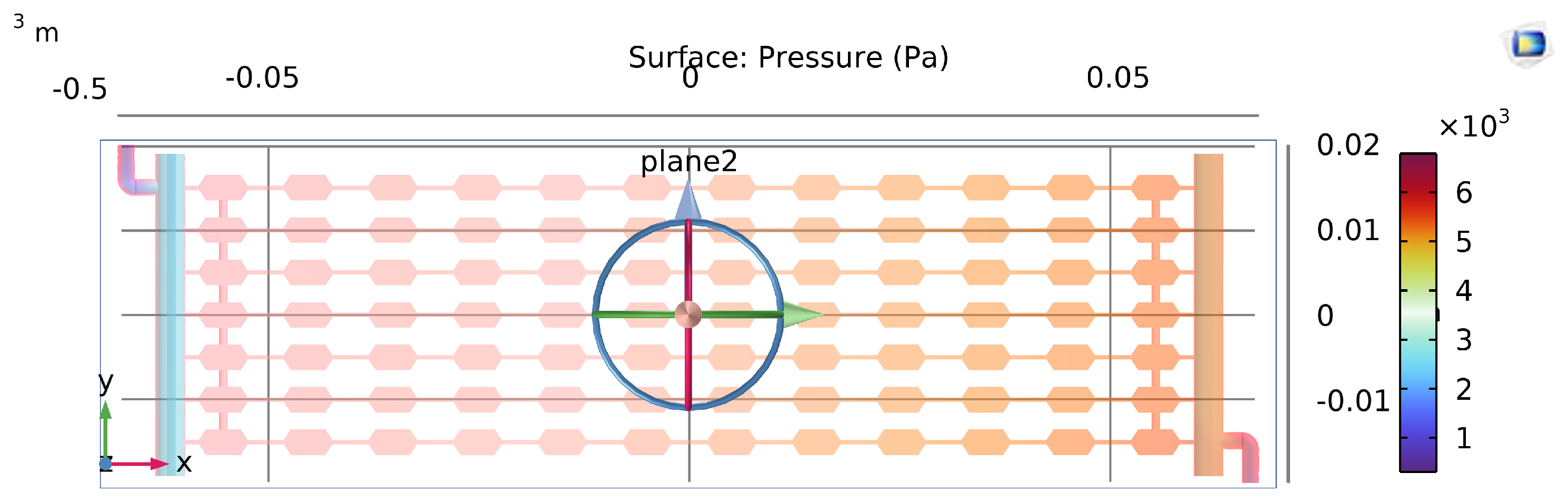
Figure 15.
Comparison of overall pressure drop for S-MC, CD-MC, and S–CD-MC. The S–CD design maintains a pressure drop comparable to CD for the representative case, indicating that thermal gains are achieved without a large hydraulic penalty.
Figure 15.
Comparison of overall pressure drop for S-MC, CD-MC, and S–CD-MC. The S–CD design maintains a pressure drop comparable to CD for the representative case, indicating that thermal gains are achieved without a large hydraulic penalty.
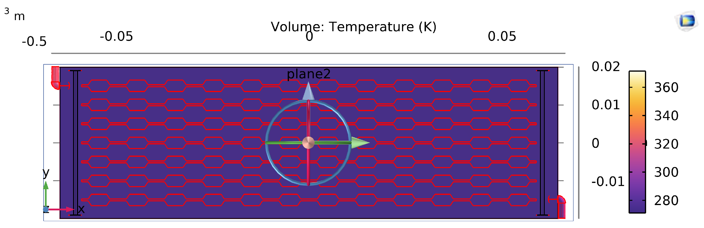
Figure 16.
Comparison of thermal resistance for S-MC, CD-MC, and S–CD-MC. Reduced for S–CD reflects lower peak temperature for the same heat input, enabled by enhanced near-wall mixing and shorter effective development length.
Figure 16.
Comparison of thermal resistance for S-MC, CD-MC, and S–CD-MC. Reduced for S–CD reflects lower peak temperature for the same heat input, enabled by enhanced near-wall mixing and shorter effective development length.
Disclaimer/Publisher’s Note: The statements, opinions and data contained in all publications are solely those of the individual author(s) and contributor(s) and not of MDPI and/or the editor(s). MDPI and/or the editor(s) disclaim responsibility for any injury to people or property resulting from any ideas, methods, instructions or products referred to in the content. |
© 2025 by the authors. Licensee MDPI, Basel, Switzerland. This article is an open access article distributed under the terms and conditions of the Creative Commons Attribution (CC BY) license (http://creativecommons.org/licenses/by/4.0/).
Copyright: This open access article is published under a Creative Commons CC BY 4.0 license, which permit the free download, distribution, and reuse, provided that the author and preprint are cited in any reuse.


