
Submitted:
25 December 2025
Posted:
26 December 2025
You are already at the latest version
Abstract
The high cost and long turnaround time of MEMS fabrication necessitate accurate pre fabrication performance prediction. For Z shaped MEMS capacitive microphones, the lack of a complete analytical model for the suspension spring constant hinders systematic optimization and often leads to costly trial and error fabrication.
This work presents a closed form energy based analytical model for Z shaped suspension arms using Castigliano’s theorem, enabling explicit derivation of the vertical spring constant and its direct link to key performance parameters. Based on this formulation, a physically grounded multi objective optimization framework is established to enhance mechanical sensitivity while satisfying resonance frequency and pull in voltage constraints. Particle swarm optimization (PSO) is employed as an efficient search strategy within the analytically defined design space.
The framework allows reliable evaluation and optimization of microphone performance before fabrication, significantly reducing design uncertainty. Simulation results show that, compared with both an initial reference design and reported state of the art Z shaped MEMS microphones, the optimized structure achieves ap-proximately a threefold improvement in open circuit sensitivity while reducing the pull in voltage by nearly 30% without compromising resonance frequency constraints. The presented approach offers a systematic, fabrication oriented design pathway applicable to a wide range of MEMS microphone structures.
Keywords:
MEMS capacitive microphone
; z-shaped diaphragm
; analytical modeling
; spring constant
; structural optimization
; particle swarm optimization (PSO)
1. Introduction
Microelectromechanical systems (MEMS) capacitive microphones are widely used in modern acoustic sensing applications due to their compact size, low power consumption, and CMOS compatibility [1,2,3]. The performance of these devices is fundamentally determined by the mechanical behavior of the diaphragm–suspension system, which directly governs key parameters such as mechanical sensitivity, resonance frequency, and pull-in voltage. Designing a microphone structure that simultaneously satisfies these conflicting requirements remains a major challenge in MEMS microphone development [4,5].
Various types of micromachined microphones have different designs, including piezoresistive, piezoelectric, and capacitive microphones, which have been investigated in various references [6,7].
The capacitive microphones, due to their better performance, such as high sensitivity, low power consumption, smooth frequency response in a wide bandwidth, low noise level, stability, and reliability, have been extensively studied [8,9,10]
Capacitive microphones are typically composed of a diaphragm that vibrates in response to incident sound waves. In conventional configurations, the diaphragm is suspended over a backplate, with an air gap between these components allowing for diaphragm displacement. Existing research has demonstrated various capacitive microphone architectures. However, the fabrication process becomes increasingly complex and expensive when employing thick backplates. Some studies [11,12,13] have proposed perforating the diaphragm as an effective solution to mitigate these manufacturing challenges while maintaining acoustic performance.
Furthermore, to improve the performance of the microphone, corrugated, slotted, posted, and spring-shaped diaphragms have also been employed [14,15,16,17,18,19,20,21].
Among various suspension configurations, Z-shaped spring arms have been proposed as an effective solution to enhance diaphragm compliance without significantly increasing the device footprint [22]. Several prior studies have reported sensitivity improvement using folded or Z-shaped suspensions; however, the majority of these works rely on finite-element simulations, parametric sweeps, or empirical trial-and-error approaches. While effective, such methods are computationally intensive and provide limited physical insight into the role of individual geometric parameters [23,24].
Some studies employed the Taguchi method to optimize the pressure sensor structure. This statistical-empirical approach utilizes orthogonal arrays and analysis of variance to select the optimal parameter combination from a limited set of experimentally tested options within a discrete design space. However, the Taguchi method does not guarantee convergence to the global optimum [25].
For this reason, optimization in MEMS design is not merely a numerical refinement step but a necessity for reducing fabrication risk [26,27]. When supported by accurate mechanical models, optimization enables designers to evaluate trade-offs among sensitivity, resonance frequency, and electrostatic stability prior to fabrication, thereby minimizing reliance on costly experimental iterations. In the absence of such models, optimization is often reduced to black-box searches with limited predictive value.
Among existing optimization techniques, Particle Swarm Optimization (PSO) is widely adopted in MEMS design due to its high computational efficiency, effectiveness in handling nonlinear design spaces, and strong capability to escape local optima. By leveraging population-based stochastic search, PSO enables systematic optimization of structural parameters, improving device performance and reducing fabrication uncertainty without reliance on gradient-based methods [28,29,30,31,32,33].
From a modeling perspective, the effectiveness of structural optimization is inherently limited by the accuracy of the underlying mechanical formulation. In Z-shaped microphone suspensions, a complete and transparent analytical derivation of the vertical spring constant, explicitly accounting for both torsion and bending deformation mechanisms, has not been fully reported. This gap restricts the formulation of physically meaningful objective functions required for systematic optimization.
In this work, a closed-form, energy-based analytical model is developed to derive the vertical spring constant of Z-shaped MEMS microphone suspensions using Castigliano’s theorem. Based on this model, a multi-objective structural optimization framework employing particle swarm optimization (PSO) is proposed to simultaneously enhance mechanical sensitivity while maintaining acceptable resonance frequency and pull-in voltage. The role of PSO in this study is to efficiently explore the design space enabled by the proposed analytical model, allowing the identification of fabrication-ready, optimized microphone designs before entering the cleanroom.
The main contributions of this paper are summarized as follows:
- A complete energy-based analytical derivation of the vertical spring constant for Z-shaped MEMS microphone suspensions.
- A physically meaningful multi-objective formulation linking diaphragm geometry to sensitivity, resonance frequency, and pull-in voltage.
- A PSO-based optimization framework that enables reliable pre-fabrication performance optimization of MEMS capacitive microphones, reducing dependence on costly trial-and-error fabrication cycles.
The article is organized in six principal sections. In the second section, a comprehensive analysis is presented: (1) the complete structure of the capacitive Z-shaped microphone, (2) accurate mathematical modeling of the spring constant derived through the energy method, and (3) calculating of its performance parameters based on spring constant. The third section establishes the optimization framework by Definition of Input and Output Parameters in PSO Implementation, defining the desired performance parameters for microphone structural optimization, and Specifying the allowable design space for component geometry variations. The fourth section introduces the basic principles of the PSO, and based on the discussed problem, the objective function is defined. Following that, in the fifth section, the optimized results and performance evaluation of the algorithm are presented, comparing the performance of the optimized structure with the initial microphone and other capacitive microphones designed in recent years. Finally, the sixth section provides a general conclusion.
2. Structure of the Z-Shaped Microphone
The structure of the MEMS capacitive Z-shaped microphone is depicted in Figure 1, and the general specifications of the microphone structure are presented in Table 1.
The geometric and physical parameters listed in Table 1 are derived from an initial fabrication-oriented reference design of the Z-shaped MEMS capacitive microphone. These values were selected by considering SOI micromachining constraints, mechanical reliability, and electrostatic stability. The diaphragm thickness, air gap, and spring-arm dimensions were determined based on the baseline layout while respecting lithography limitations and pull-in voltage constraints, and the bias voltage range was chosen to ensure compatibility with low-voltage electronic interfaces.
Consequently, the parameters in Table 1 define a realistic and manufacturable design space for subsequent analytical modeling and structural optimization, rather than arbitrarily chosen values.
As shown in Figure 1, silicon dioxide is used to create an air gap between the diaphragm and the backplate, and the diaphragm material is single-crystal silicon. Additionally, to reduce damping issues and simplify the manufacturing process, the diaphragm has been perforated. Z-shaped arms have also been added around the diaphragm to enhance sensitivity. Due to the hardness and mechanical strength resembling steel, single-crystal silicon is an ideal material for many microelectromechanical structures. Furthermore, single-crystal silicon can be manufactured with almost no stress. However, microphones with single-crystal silicon diaphragms may not provide optimal performance due to the thickness of the diaphragm, as high diaphragm thickness leads to a reduction in the mechanical sensitivity of the microphone [34,35].
The sensitivity of capacitive microphones is positively influenced by an increase in diaphragm dimensions, higher supply voltages, a reduction in air gap distance, and decreased residual stress in the diaphragm. Due to the inherent trade-offs among various performance parameters, a structural design must be developed that achieves an optimal balance between all of these factors. Indeed, the implementation of the aforementioned structure with Z-shaped arms enables the designer to achieve a microphone with optimal performance characteristics.
2.1. Mathematical Modeling of Z-Shape Arms Spring Constant
In this work, a complete closed-form analytical formulation based on the energy method and Castigliano’s theorem is presented, providing a transparent and reproducible model for the vertical stiffness of the Z-shaped diaphragm suspension. The derived model establishes a direct and physically interpretable relationship between structural geometry and mechanical stiffness, making it particularly suitable for systematic and performance-aware structural optimization.
In the subsequent analysis, both residual stresses and extensional stresses are neglected. First, the free-body diagram is developed through segmentation of the designated arm, based on the diaphragm schematic and arm configuration based on Figure 1. A vertical force Fz is applied to the free-ended part of the arm, resulting in a displacement δz. The z-axis orientation was selected to represent the vertical spring constant.
Figure 2.
Free-body diagram for one of the Z-shaped arms.
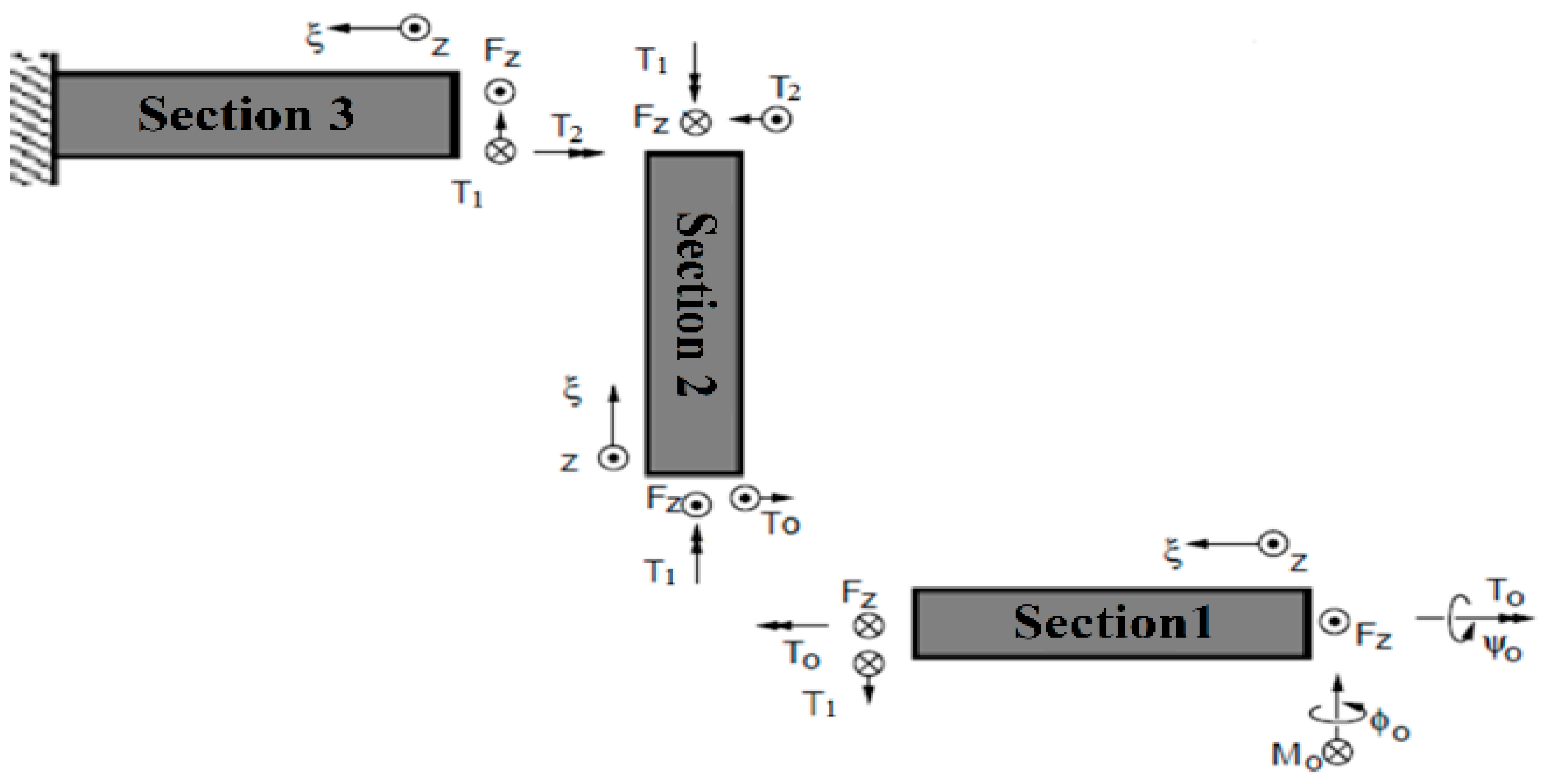
Because of the diaphragm’s symmetrical design, the beam’s end angle θ₀ naturally stays at zero. Rotation is limited through the application of an external bending moment M₀ in the finite element analysis. Where each section is described using its local coordinate system. The bending and torsional moments for each section (M3, M2, M1, T3, T2, T1) are defined as follows:
Bending moments of section 1:
Torsional moments of section 1:
Bending moments of section 2:
Torsional moments of section 2:
Bending moments of section 3:
Torsional moments of section 3:
The ξ-axis is defined parallel to the longitudinal direction of each arm section. The end angle of the arm is maintained at zero due to structural symmetry. Rotation is constrained in the analysis through application of an external bending moment M₀. For calculation of the arm’s strain energy in the z-direction, the following expression is derived:
A combination of Castigliano’s second theorem and the zero end-angle condition (θ₀=0) produces a functional relationship between the external moment and applied load.
For analytical convenience, the following parameter definitions are defined:
Where E is the Young’s modulus, G is the shear modulus, I is the moment of inertia, and J is the torsional constant. Consequently, Equation (8) can be expressed in the following form:
Through rearrangement of the equation terms,
By applying common denominators to both sides,
The relationship between the bending moment and applied force is obtained as follows:
Through application of the angular constraint (φ₀), a relationship between the torsional moment and applied load is derived as follows:
By solving equation (19) and utilizing equations (9) through (14), the following expression is obtained:
Through rearrangement of the equation (20) terms,
The relationship between the torsional moment and applied force is obtained as follows:
Using Castigliano’s second theorem, the vertical displacement can be expressed as:
By substituting the derived bending and torsional moment relationships into the equation (23), the following expression is obtained:
Through integration of Equation (24), the relationship between displacement and applied force (Fz) can be derived as follows:
Using the above relationship, the spring constant of a Z-shaped arm can be readily calculated by dividing the applied force by the resulting displacement.
Consequently, the diaphragm’s spring constant in the z-direction is four times of a single arm, as follows:
Where its unit is kilo newton per meter (kN/m). Given the potential applicability of Z-shaped flexure arms in MEMS component design—including pressure sensors and accelerometers—a precise understanding of their spring constant relationship is critically important for performance optimization.
2.2. Mathematical Modeling of the Microphone Performance Parameters
Given that the arm design ensures uniform deflection of the central diaphragm, and based on the spring constant calculated in the section 2.1, the microphone’s performance parameters can be derived.
2.2.1. Resonance Frequency
One of the key parameters in evaluating microphone performance is the resonance frequency. The structure’s resonance frequency depends on various parameters including geometry and material properties. The diaphragm’s resonance frequency can be defined as follows:
Where k is the diaphragm’s spring constant and m represents the diaphragm mass, which are calculated as follows:
Where ρ denotes the density, Aeff represents the diaphragm effective area, and t corresponds to the diaphragm thickness. By substituting Equations (27) and (29) into Equation (28), the resonance frequency of the Z-shaped arm microphone can be determined as follows:
2.2.2. Mechanical Sensitivity
The mechanical sensitivity of the microphone is defined as the diaphragm displacement (W) induced by the applied pressure (P). Consequently, the mechanical sensitivity can be expressed as follows:
The relationship between the applied force (F) and the spring stiffness (k) follows Hooke’s Law.
The relationship between the applied force and the pressure is given by the following equation:
Consequently, the microphone’s mechanical sensitivity can be determined as:
2.2.3. Pull-In Voltage
The pull-in voltage is a critical concept in microelectromechanical systems (MEMS), particularly in electrostatic sensors. It is defined as the minimum voltage required to cause the sudden attraction (pull-in effect) between diaphragm and back plates within a MEMS microphone.
For a simple parallel-plate structure with an initial gap distance (d0), the pull-in voltage (Vpull−in) can be approximated using the following equation:
Then the pull-in voltage relationship for a microphone with a Z-shaped microphone can be calculated as follows:
3. Proposed Method for Optimization of the Microphone Structure
The term ‘MEMS Technology’ denotes the combined electrical and mechanical physics, which inherently creates design challenges. Most MEMS fabrication works utilize approximate trial-and-error processes often resulting in initial designs with incompletely characterized performance and non-optimal configurations.
The optimization method which is presented in this work for the microphone design is an attractive area of discussion. The utilization of optimization algorithms with optimal dimensions can undoubtedly lead to a significantly improved performance. The design components have been optimized using the PSO algorithm.
3.1. Definition of Designing Parameters
The design process is initiated by selecting the initial Z-shaped microphone configuration. Given that the performance characteristics of this structure have been precisely modeled through computational methods, an optimized design can be systematically achieved using the particle swarm optimization algorithm. Certain structural parameters, including diaphragm length and thickness, perforation count and width, and air gap dimensions, are maintained as fixed variables throughout the optimization process. This particular design incorporates a 300-micron diaphragm. The special consideration must be given during the optimization process to ensure the microphone’s resonant frequency remains outside the audible spectrum (20 kHz). Accordingly, three key performance metrics - resonant frequency, pull-in voltage, and mechanical sensitivity - have been selected as optimization targets. The pull-in voltage, defined as the critical potential difference causing collapse of the movable electrode onto its stationary counterpart, requires particular attention.
As illustrated in Figure 1, the diaphragm is supported by four arms, each comprising three beams. Consequently, determining the optimal length and width of these beams is a critical consideration in the design process. Figure 3 presents an overview of the proposed model for optimizing the Z-shaped microphone. The model employs an optimization algorithm to select key geometric parameters of the microphone structure, such as beam dimensions. The examined structural parameters include the following:
In the proposed methodology, six critical structural parameters are required to be optimized through the algorithmic process. The key performance metrics investigated in this study comprise the resonant frequency, pull-in voltage, and mechanical sensitivity of the microphone.
3.2. Performance Specifications of the Capacitive Z-Shaped Microphone
The optimization process is performed to determine the optimal structural configuration for simultaneously reducing the supply voltage and enhancing microphone’s sensitivity, while adhering to the resonance frequency constraint. As specified in Table 2, the target design space for microphone performance optimization is defined, with a minimum resonance frequency threshold of 30 kHz selected to ensure operation within the audible frequency range.
For this structure with a supported diaphragm by Z-shape arms, six design variables (L1, L2, L3, w1, w2, w3) are defined. Based on design constraints, the system yields three independent and three dependent variables. Independent variables are considered with configuration matrix Xz as follows:
In this design, given the structural constraints regarding the formation of a 5-micron gap between the arm and the body, three additional variables dependent on these three main variables will be introduced. These relationships are defined as follows:
WD represents the length of the diaphragm, with 300 microns width.
The Variation ranges for the independent variables has been determined based on the condition that the width of each arm section should vary between 20 and 30 microns, as given in Table 3.
The objective of optimization is to achieve a microphone with optimal performance. To evaluate microphone performance, three key parameters are analyzed: resonance frequency, mechanical sensitivity, and pull-in voltage. Thus, the objective function must be defined in such a way that all three mentioned parameters are improved. Mechanical sensitivity has been utilized due to its independence from bias voltage.
4. PSO Algorithm
The PSO algorithm is initialized with a population of randomly generated particles within the search space. The optimization process proceeds through iterative solution updates, where particle route are continuously adjusted based on both individual and collective experiences. The flowchart of the PSO algorithm is illustrated in Figure 4.
In this N-dimensional solution space, each particle’s position represents a potential solution, while its velocity vector determines the direction of exploration. The fitness of each particle is evaluated according to the predefined objective function. During the optimization process, two key parameters guide particle movement: The personal best solution (pbest) encountered by each individual particle is maintained, and the global best solution (gbest) discovered by the entire swarm is preserved.
The fundamental principle of PSO involves the convergence of particles toward optimal regions through velocity updates. These updates incorporate: the particle’s current velocity, its displacement from pbest, its displacement from gbest.
The velocity adjustment is modulated by random acceleration coefficients at each iteration. Following the identification of optimal positions, particle velocities and locations are systematically updated according to established mathematical formulations as follows:
The velocity of the i-th particle at the k-th iteration, denoted as Vik, is determined by three key components: the particle’s previous velocity, its personal best position (pbest), and the global best position (gbest) of the swarm. The weighting function (w) controls the inertia of the particle. Cj is the weighting or learning factor. A uniformly distributed random number (rand) between 0 and 1 introduces stochastically, ensuring exploration of the search space.
The position update is governed by the particle’s current position Sik and its newly computed velocity. Conventionally, the acceleration coefficients are set to c1=c2=2, balancing the trade-off between individual and social learning. Eq.44 ensures that particles efficiently converge toward optimal regions while maintaining diversity in the search process.
Where represents the position of the i-th particle at the k-th iteration.
Objective Function Definition
The objective function is formulated based on the analytical spring constant model derived in Section 2. The novelty of the proposed optimization lies not in the PSO algorithm itself, but in the formulation of a physically grounded objective function that directly links diaphragm geometry to key performance metrics, including sensitivity, resonance frequency, and pull-in voltage. This approach enables a constrained and physically meaningful optimization of the Z-shaped MEMS microphone.
The optimization objective is to enhance the overall performance of the microphone. To evaluate its performance, three critical parameters are considered: resonance frequency, mechanical sensitivity, and Pull-in Voltage. Therefore, the objective function must be formulated to simultaneously improve all three parameters. The fitness value of each particle is determined by evaluating this objective function, with the optimization process aimed at minimizing the function. Accordingly, the objective function is defined as follows:
The equations obtained for resonance frequency, mechanical sensitivity, and Pull-in Voltage in Section 2 are used to achieve the objective function. In fact is a part of the objective function for optimizing the resonance frequency, which is defined as:
where is the desired minimum frequency, set to 30 kilohertz according to Table 2. The coefficient (a1) of Z_fr in Eq.4 is defined in such a way that if , this coefficient becomes zero. Otherwise, it becomes one.
is a part of the objective function for optimizing the mechanical sensitivity of the structure, defined as follows:
where is the desired minimum mechanical sensitivity, set to 1 nanometer per Pascal according to Table 2. The coefficient is defined in such a way that if , this coefficient becomes zero; otherwise, it becomes one.
is a part of the objective function for optimizing the Pull-in Voltage and is defined as follows:
where is the desired maximum Pull-in Voltage, set to 9 volts according to Table 2. The coefficient is defined in such a way that if , this coefficient becomes zero; otherwise, it becomes one.
Consequently, the Particle Swarm Optimization algorithm is employed to minimize the objective function (Z) through iterative adjustment of the arm structure’s primary design variables. The algorithm’s output yields optimized geometric dimensions for the microphone’s arms, simultaneously satisfying three critical performance criteria: Maintaining the resonant frequency within the target operational range, ensuring mechanical sensitivity exceeds the minimum required, and constraining the Pull-in Voltage below the specified limit.
This multi-objective optimization strategy intelligently navigates the design trade-offs, carefully balancing between different parameters requirements to deliver superior microphone performance. Through an iterative refinement process, the algorithm identifies design configurations that meet all critical performance benchmarks while maintaining optimal functionality across operational parameters.
5. Discussion and Results Analysis
In the design of MEMS capacitive microphones, achieving an optimal balance among resonance frequency, mechanical sensitivity, and pull-in voltage is essential due to their inherently conflicting nature. Increasing mechanical compliance enhances sensitivity while simultaneously reducing resonance frequency and electrostatic stability. Therefore, a systematic optimization strategy is required to identify a fabrication-ready design that satisfies all performance constraints.
From a fabrication perspective, the availability of a closed-form analytical model enables reliable pre-fabrication performance prediction, thereby reducing costly trial-and-error iterations and mitigating manufacturing risk in MEMS microphone development.
Based on the analytical performance models derived in Section 2, the microphone dimensions were optimized using the multi-objective formulation defined in Equation (4). The target performance specifications used to guide the optimization process are summarized in Table 2. By explicitly linking geometric parameters to physical performance metrics through the analytical spring-constant model, the optimization framework avoids empirically driven parameter tuning.
The particle swarm optimization (PSO) algorithm was employed to explore the defined design space, with a conservative maximum of 200 iterations to ensure adequate global search capability. Convergence of the objective function was achieved within 82 iterations, indicating effective navigation of the design space enabled by the proposed analytical formulation.
The resulting optimized design satisfies the specified resonance frequency and pull-in voltage constraints while exhibiting a significant improvement in mechanical sensitivity. These results confirm that the observed performance enhancement originates from the physically grounded analytical model rather than from algorithm-specific tuning, enabling reliable pre-fabrication performance prediction.
5.1. Evaluation of the Optimized Structure
The dimensional characteristics of the Z-shaped microphone’s support arms are presented in Table 4, comparing both the initial design configuration [22] and the optimized parameters obtained through Particle Swarm Optimization method.
The performance characteristics of the original and optimized microphone designs were compared using the optimal configuration determined by the Particle Swarm Optimization algorithm, which results are given in Table 5.
It has been observed that, through the selection of optimal design parameters, the open circuit sensitivity of the microphone has been increased by approximately three times compared to the initial dimensions. Additionally, the pull-in voltage has been reduced to nearly one- third of its previous value.
Notably, it has been stated that all major structural parameters, with the exception of the arm dimensions, have been held constant. This suggests that the optimal adjustment of the length and width of the arms alone can yield a significantly improved microphone with enhanced performance characteristics.
5.2. Comparison
To assess the performance of the optimized microphone, its functional parameters are compared with those reported in prior studies. Given that different microphones are designed with varying objectives, such as minimizing pull-in voltage, enhancing sensitivity, broadening bandwidth, or reducing overall dimensions, a comprehensive merit factor must be established to enable a fair and meaningful comparison across these key performance metrics. Since all key parameters—including bandwidth, open-circuit sensitivity, supply voltage, and diaphragm area—are interdependent, a design that yields a higher merit factor is considered preferable. To facilitate a consistent comparison of microphone performance across different studies, the Figure of Merit (FOM) is defined as follows:
In the above formula, represents the resonance frequency, is the open-circuit sensitivity, is the applied supply voltage, and is the diaphragm area. A comparative analysis of the proposed optimized Z-shaped microphone’s performance against existing capacitive microphone designs is provided in Table 6.
As shown in Table 6, the optimized Z-shaped microphone demonstrates superior performance characteristics, attaining the highest figure of merit among comparable reported in the literature.
6. Conclusion
In this paper, a complete energy-based analytical formulation was developed and employed as the foundation for performance-aware structural optimization of a Z-shaped MEMS capacitive microphone. Given the high cost, long turnaround time, and limited iteration capability of MEMS fabrication processes, particular emphasis was placed on pre-fabrication optimization as an effective means of improving device performance while reducing fabrication uncertainty. The proposed closed-form, physically grounded analytical model enables reliable performance prediction without reliance on exhaustive numerical simulations.
The main contribution of this work lies in integrating the transparent analytical model with a model-driven multi-objective optimization framework to address the inherently coupled trade-offs in MEMS microphone design. By explicitly capturing the relationships among resonance frequency, mechanical sensitivity, and pull-in voltage, the formulated objective function enables a realistic and constrained exploration of the design space based on physical performance relationships rather than empirical tuning.
Through systematic optimization of the Z-shaped diaphragm arm geometry, the open-circuit sensitivity was increased by approximately threefold, while the pull-in voltage was reduced by nearly one-third compared to the initial reference design. These improvements were achieved primarily by tuning the length and width of the diaphragm support arms, while all other structural parameters were kept unchanged, confirming the effectiveness of the proposed modeling-based optimization approach.
Overall, the presented framework offers a robust and computationally efficient alternative to conventional trial-and-error or brute-force simulation-based design strategies. Owing to its generality and physical grounding, the methodology can be readily extended to other MEMS microphone and sensor architectures governed by coupled mechanical–electrostatic trade-offs that require careful optimization under practical manufacturing constraints.
Author Contributions
Conceptualization, methodology, formal analysis, investigation, data curation, and writing—original draft preparation, S.B.S.; supervision and writing—review and editing, B.A.G.; minor assistance in manuscript preparation, F.S. All authors have read and agreed to the published version of the manuscript.
Funding
This research received no external funding.
Data Availability Statement
The data presented in this study are available on request from the corresponding author.
Conflicts of Interest
The authors declare no conflict of interest.
References
- Kumar, A.; Varghese, A.; et al. MEMS-based piezoresistive and capacitive microphones: A review on materials and methods. Materials Science in Semiconductor Processing 2024, 169, 107879. [Google Scholar] [CrossRef]
- Lu a, L.; Liu, W.; et al. A piezoelectric MEMS microphone with proof mass and its array. Sensors & Actuators: A. Physical 2024, 377, 115735. [Google Scholar]
- Liu, Y.; Li, C.; et al. Ultra-high sensitivity fiber optic microphone with corrugated graphene-oxide diaphragm for voice recognition. Nano Research 2024, 17(8), 7593–7602. [Google Scholar] [CrossRef]
- Zhengzx, Z.; Wang, C. Micro-Electro-Mechanical Systems Microphones: A Brief Review Emphasizing Recent Advances in Audible Spectrum Applications. Micromachines 2024, 15, 352. [Google Scholar]
- Cyr, B.; Sumaria, V.; et al. How Lasers Exploit Photoacoustic and Photoelectric Phenomena to Inject Signals into MEMS Microphones. Journal of Hardware and Systems Security 2025. [Google Scholar] [CrossRef]
- Ali, W.R.; Prasad, M. Design and Fabrication of Piezoelectric MEMS Sensor for Acoustic Measurements. Silicon 2022, 14, 6737–6747. [Google Scholar] [CrossRef]
- Hegde, V.; Design, N.C. fabrication and experimental analysis of piezoresistive bidirectional acoustic sensor. Sensor Review 2024, 44, 284–289. [Google Scholar] [CrossRef]
- Sedaghat, S.B.; Ganji, B.A. Design and modeling of a highly sensitive microelectromechanical system capacitive microphone. J. Micro/Nanolith. MEMS MOEMS 2020, 19(2), 025001. [Google Scholar] [CrossRef]
- Zawawi, S.A.; Hamzah, A.A.; et al. A Review of MEMS Capacitive Microphones. Micromachines 2020, 11(5). [Google Scholar] [CrossRef]
- Duanmu, Z.; Kong, C.; et al. Design and implementation of an acoustic-vibration capacitive MEMS microphone. AIP Advances 2022, 12. [Google Scholar] [CrossRef]
- Ganji, B.A.; Majlis, B.Y. Design and fabrication of a new MEMS capacitive microphone using a perforated aluminum diaphragm. Sensors and Actuators A: Physical 2009, 149, 29–37. [Google Scholar] [CrossRef]
- Kimori, N.; Kumai, Y.; Hishinuma, S.; Ikehara, T. Ten-micrometer-thick Silicon Diaphragm Used in Condenser Microphone. In Key Engineering Materials; Trans Tech Publications, 2013; Vol. 538, pp. 277–280. [Google Scholar]
- Yildiz, F. Frequency and sensitivity evaluation of perforated low temperature co-fired ceramic (LTCC) diaphragm. Microsystem technologies 2024. [Google Scholar]
- Taybi, M.; Ganji, B.A. The Effect of Corrugations on Mechanical Sensitivity of Diaphragm for MEMSCapacitive Microphone. IJE TRANSACTIONS B: Applications 2013, 26(11), 1323–1330. [Google Scholar]
- Auliya, R.Z.; Choon, P.; et al. 3D finite element analysis of corrugated silicon carbide membrane for ultrasonic MEMS microphone applications. Microsystem Technologies 2021, 27, 913–919. [Google Scholar] [CrossRef]
- Ganji, B.A.; Sedaghat, S.B.; et al. Design and fabrication of high performance condenser microphone using C-slotted diaphragm. Microsystem Technologies 2018, 24, 3133–3140. [Google Scholar] [CrossRef]
- Nademi, N.; Javad karamdel; et al. A new method to increase MEMS microphone sensitivity using small circular diaphragm with fixed center. Microsystem Technologies 2017, 23, 5407–5413. [Google Scholar] [CrossRef]
- Sedighe Babaei Sedaghat, Bahram Azizollah Ganji, “A novel MEMS capacitive microphone using spring-type diaphragm” Microsystem Technologies (2018).
- Shubham; Seo, Y. A Novel MEMS Capacitive Microphone with Semiconstrained Diaphragm Supported with Center and Peripheral Backplate Protrusions. micromachines 2022, 13, 22. [Google Scholar] [CrossRef]
- Ganji, B.A.; Sedaghat, S.B.; Roncaglia, A.; et al. Design, modeling, and fabrication of crab-shape capacitive microphone using silicon-on-isolator wafer. Journal of Micro/Nanolithography MEMS, and MOEMS 2018, 17, 015002–9. [Google Scholar] [CrossRef]
- Mohamad, N.; Iovenitti, P.; Vinay, T. High sensitivity capacitive MEMS microphone with spring supported diaphragm – art. no. 68001T. Proceedings of SPIE—the international society for optical engineering, 2008; Vol. 6800. [Google Scholar]
- Ganji, B.A.; Sedaghat, S.B.; Roncaglia, A.; et al. Design and fabrication of very small MEMS microphone with silicon diaphragm supported by Z-shape arms using SOI wafer. Solid-State Electronics 2018, 148, 27–34. [Google Scholar] [CrossRef]
- Sun, C.; Sang, J.; et al. Sensitivity Analysis for Dual-Membrane Capacitive MEMS Microphone. IEEE SENSORS JOURNAL 2024, 24(15), 24015–24022. [Google Scholar] [CrossRef]
- Sedaghat, S.B.; Ganji, B.A.; Ansari, R. Design and modeling of a frog-shape MEMS capacitive microphone using SOI technology. Microsystem Technologies 2018, 24, 1061–1070. [Google Scholar] [CrossRef]
- Fawzy, A.; Magdy, A.; Hossam, A. A piezoelectric MEMS microphone optimizer platform. Alexandria Engineering Journal 2022, 61, 3175–3186. [Google Scholar] [CrossRef]
- Paing Soe Thu, Phyo Win Tun, “Design and Optimization of MEMS Comb Type Capacitive Accelerometer”, 2023 Seminar on Networks, Circuit and Systems (NCS) (2023).
- Ren, X.; Liu, X.; et al. Design and Optimization of a Pressure Sensor Based on Serpentine-Shaped Graphene Piezoresistors for Measuring Low Pressure. Sensors22 2022, 13. [Google Scholar] [CrossRef] [PubMed]
- Lv, M.; Li, P.; et al. Design and Optimization of MEMS Resonant Pressure Sensors with Wide Range and High Sensitivity Based on BP and NSGA-II. Micromachines 2024, 15(4). [Google Scholar] [CrossRef]
- Wang, H.; Nie, W.; et al. Topology and Size Optimization of MEMS Electrothermal U-Shaped Actuator. IEEE SENSORS JOURNAL 2025, 25(9), 14893–14901. [Google Scholar] [CrossRef]
- Wang, X.; Cao, H. Improved VMD-ELM Algorithm for MEMS Gyroscope of Temperature Compensation Model Based on CNN-LSTM and PSO-SVM. Micromachines 2022, 13(12). [Google Scholar] [CrossRef] [PubMed]
- Wang, X.; Cui, Y. Temperature compensation model of MEMS multi-ring disk solid wave gyroscope based on RIME-VMD and PSO-DBN multi fusion algorithm. Sensors & Actuators: A. Physical 2025, 385, 116285. [Google Scholar]
- Huang, H.; Ye, W. Temperature Compensation Method for MEMS Ring Gyroscope Based on PSO-TVFEMD-SE-TFPF and FTTA-LSTM. Micromachines 2025, 16(5), 507. [Google Scholar] [CrossRef]
- Han, S.; Xie, J. Startup Drift Compensation of MEMS INS Based on PSO–GRNN Network. Micromachines 2025, 16, 524.J. [Google Scholar] [CrossRef]
- Miao; Lin, R.; Chen, L.; Zou, Q.; Lim, S.Y.; Seah, S.H. Design considerations in micromachined silicon microphones. Microelectronic Journal 2002, 33, 21–28. [Google Scholar] [CrossRef]
- Scheeper, P.R.; Vanderdonk, A.G.H.; Olthuis, W.; Bergveld, P. Fabrication of Silicon Condenser Microphones Using Single Wafer Technology. journal of microelectromechanical systems 1992, 1, 147–154. [Google Scholar] [CrossRef]
- Gharaei, H.; Koohsorkhi, J. Design and characterization of high sensitive MEMS capacitive microphone with fungous coupled diaphragm structure. Microsystem technologies 2014, 22, 401–411. [Google Scholar] [CrossRef]
Figure 1.
Z-shaped Microphone, a) Cross section View. b) Top View of the Diaphragm.
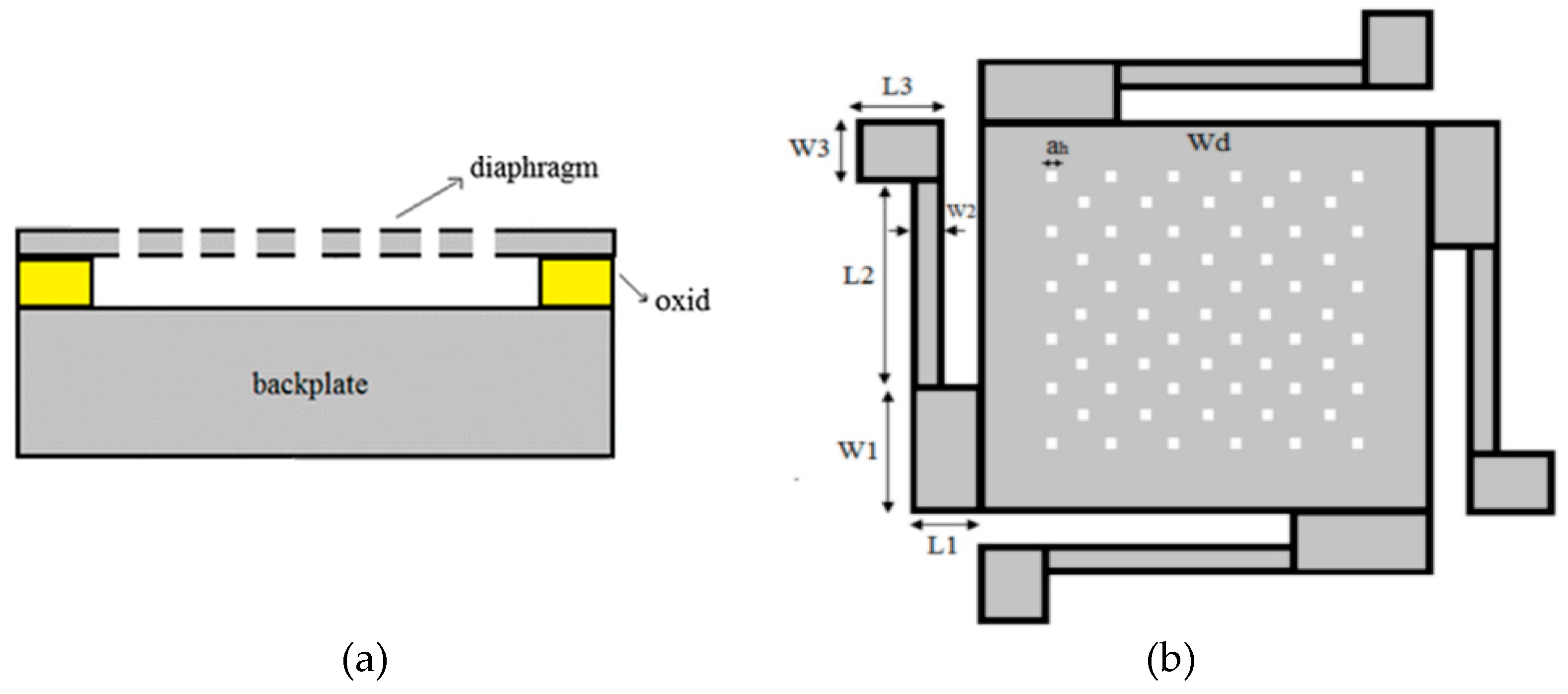
Figure 3.
Pattern of input and output parameters of the optimization algorithm.
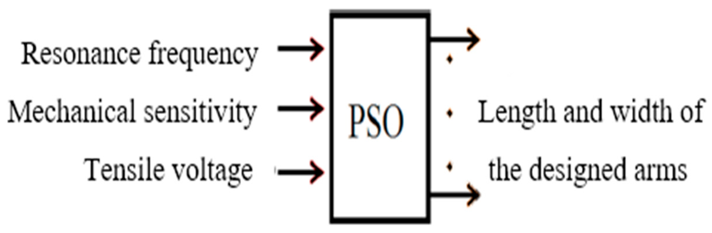
Figure 4.
Particle Swarm Optimization Algorithm Flowchart.
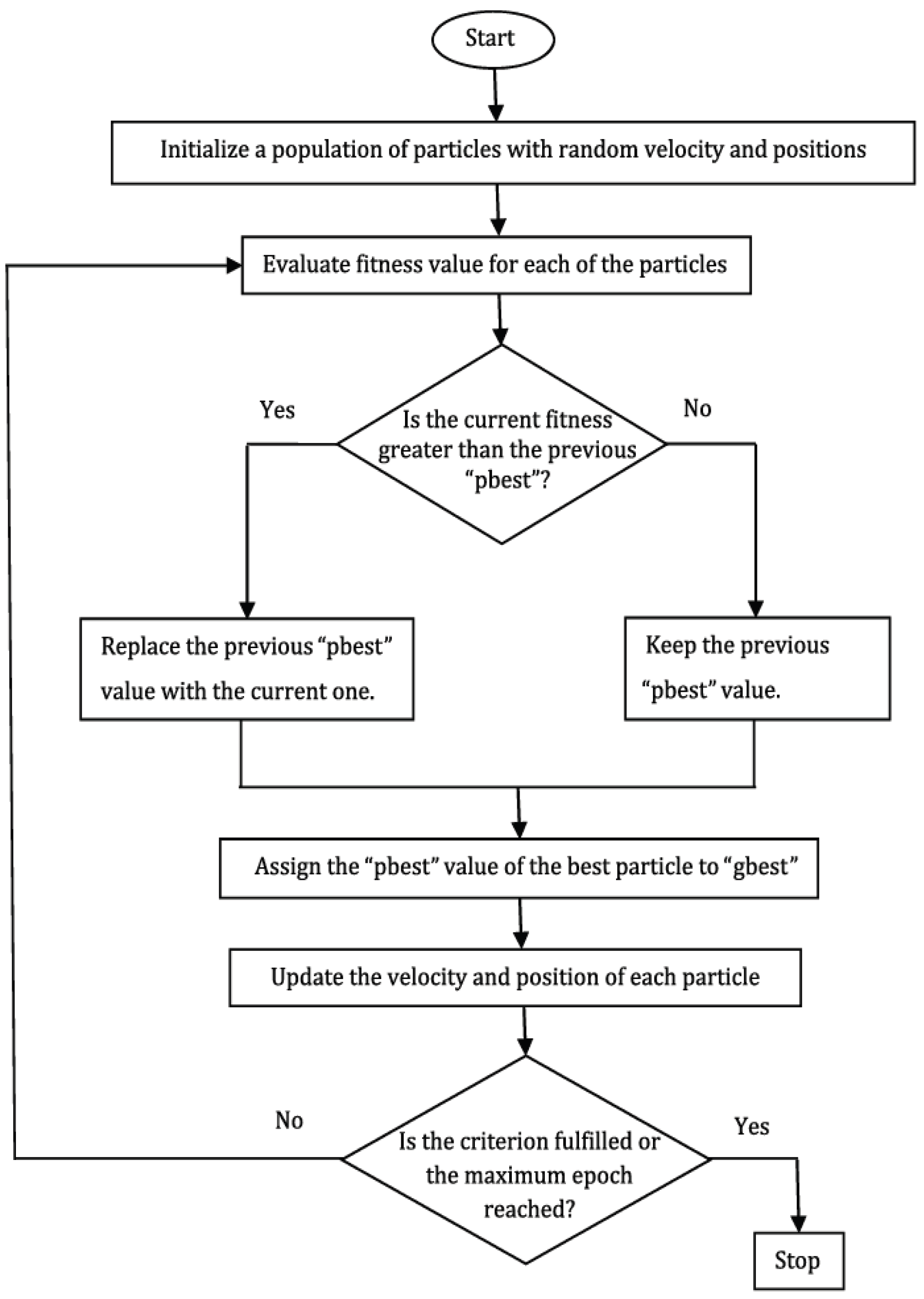

Table 1.
Physical Parameters of the Microphone Structure.
| Specifications | Values |
|---|---|
| Diaphragm Material | Single-crystal Silicon |
| Diaphragm Length | 300μm |
| Diaphragm Thickness | 5μm |
| Number of Holes | 421 |
| Hole Width | 5μm |
| Air Gap Thickness | 1μm |
| Young’s Modulus | 130GPa |
| Poisson’s Ratio | 0.28 |
Table 2.
The target design space.
| Desirable objectives | ranges |
|---|---|
| Resonance frequency (kHz) | |
| Mechanical sensitivity (nm/Pa) | |
| Pull-in Voltage (V) |
Table 3.
Variation ranges of the independent variables.
| Designing parameters | Variation ranges |
|---|---|
| L3(µm) | -- |
| L2(µm) | 275-285 |
| L1(µm) | -- |
| W3(µm) | 20-30 |
| W2(µm) | 20-30 |
| W1(µm) | -- |
Table 4.
Initial and optimized dimensions of the Z-shaped microphone.
| Designing Parameters | Initial Structure | Optimized Structure |
|---|---|---|
| L1 (μm) | 35 | 35 |
| L2 (μm) | 145 | 281 |
| L3 (μm) | 45 | 25 |
| W1 (μm) | 95 | 22 |
| W2 (μm) | 30 | 20 |
| W3 (μm) | 95 | 22 |
Table 5.
Comparison of the performance of the Z-shaped microphone with the initial and optimized dimensions.
Table 5.
Comparison of the performance of the Z-shaped microphone with the initial and optimized dimensions.
| Z-shaped microphones | fr (kHz) | VPull-in (V) | Soc (mV/Pa) |
|---|---|---|---|
| Initial Structure [22] | 85 | 10.4 | 1.75 |
| Optimized Structure | 30.2 | 3.7 | 5.4 |
Disclaimer/Publisher’s Note: The statements, opinions and data contained in all publications are solely those of the individual author(s) and contributor(s) and not of MDPI and/or the editor(s). MDPI and/or the editor(s) disclaim responsibility for any injury to people or property resulting from any ideas, methods, instructions or products referred to in the content. |
© 2025 by the authors. Licensee MDPI, Basel, Switzerland. This article is an open access article distributed under the terms and conditions of the Creative Commons Attribution (CC BY) license.
Copyright: This open access article is published under a Creative Commons CC BY 4.0 license, which permit the free download, distribution, and reuse, provided that the author and preprint are cited in any reuse.


