Preprint
Article

This version is not peer-reviewed.

Optimal CeO₂ Doping for Synergistically Enhanced Mechanical, Tribological, and Thermal Properties in Zirconia Ceramics

Submitted:

19 December 2025

Posted:

22 December 2025

You are already at the latest version

Abstract

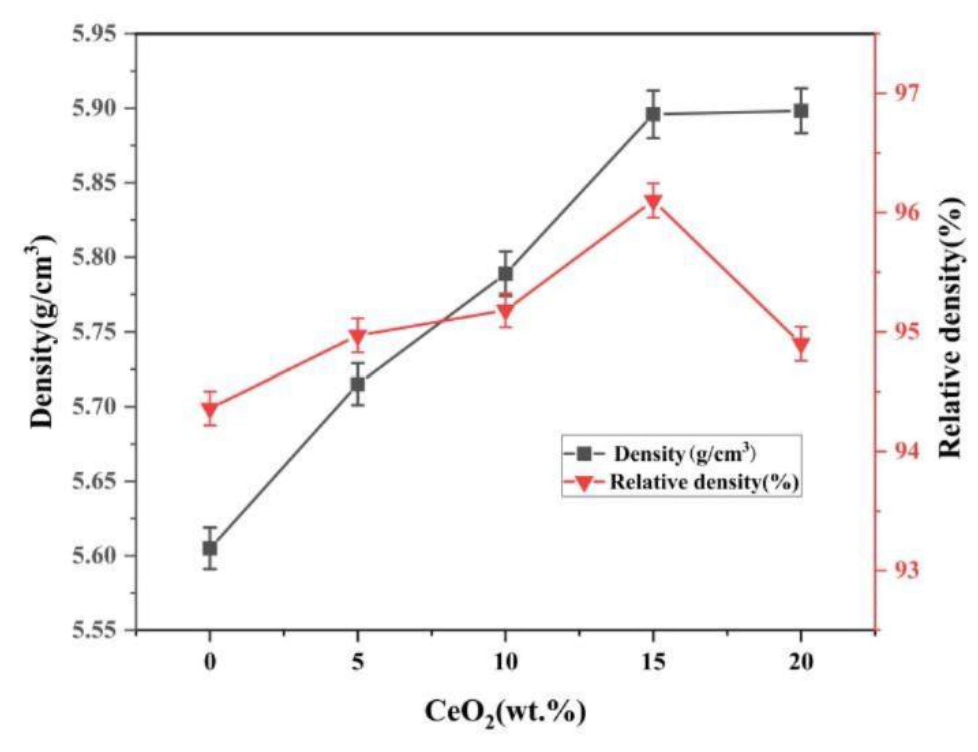
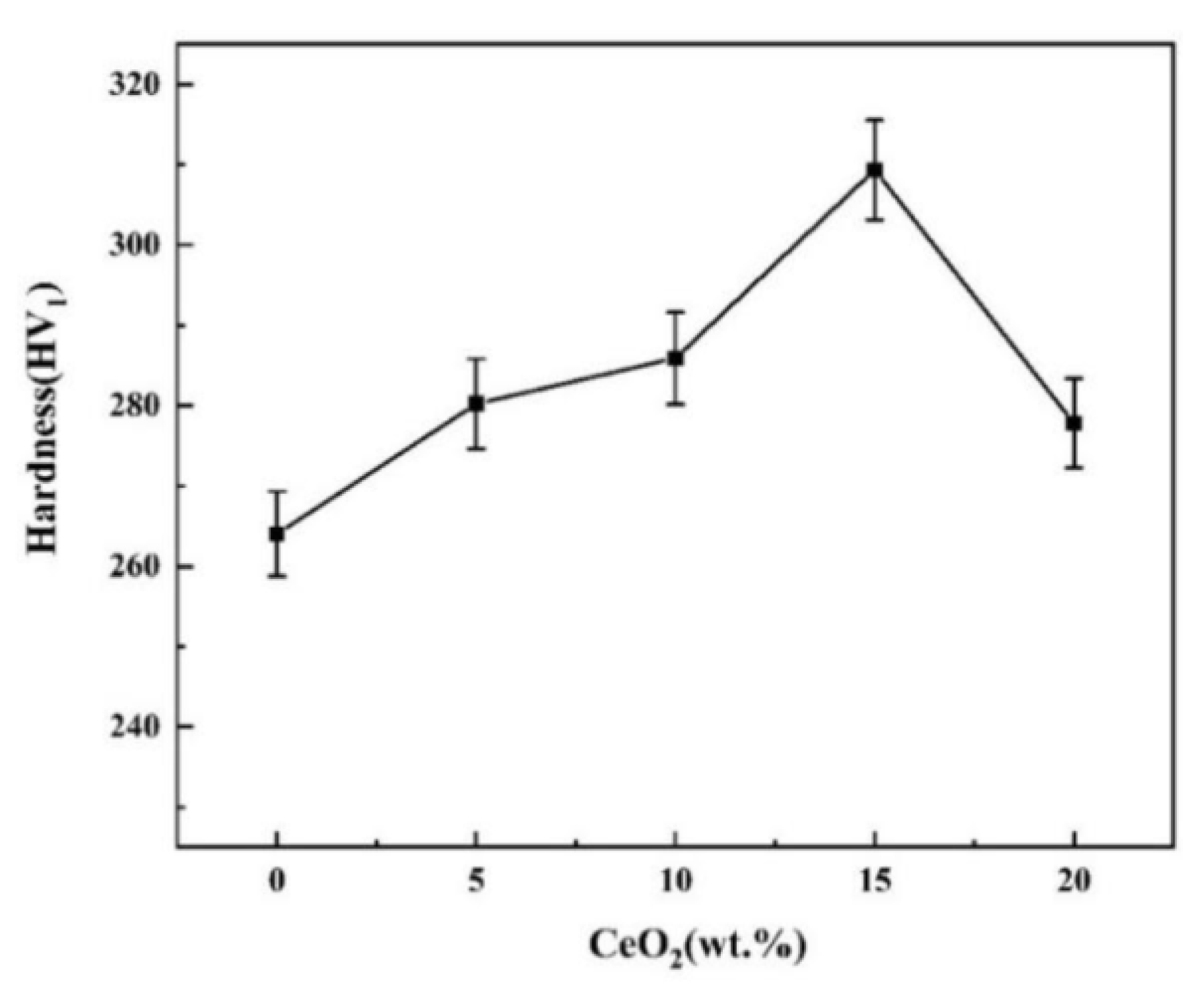
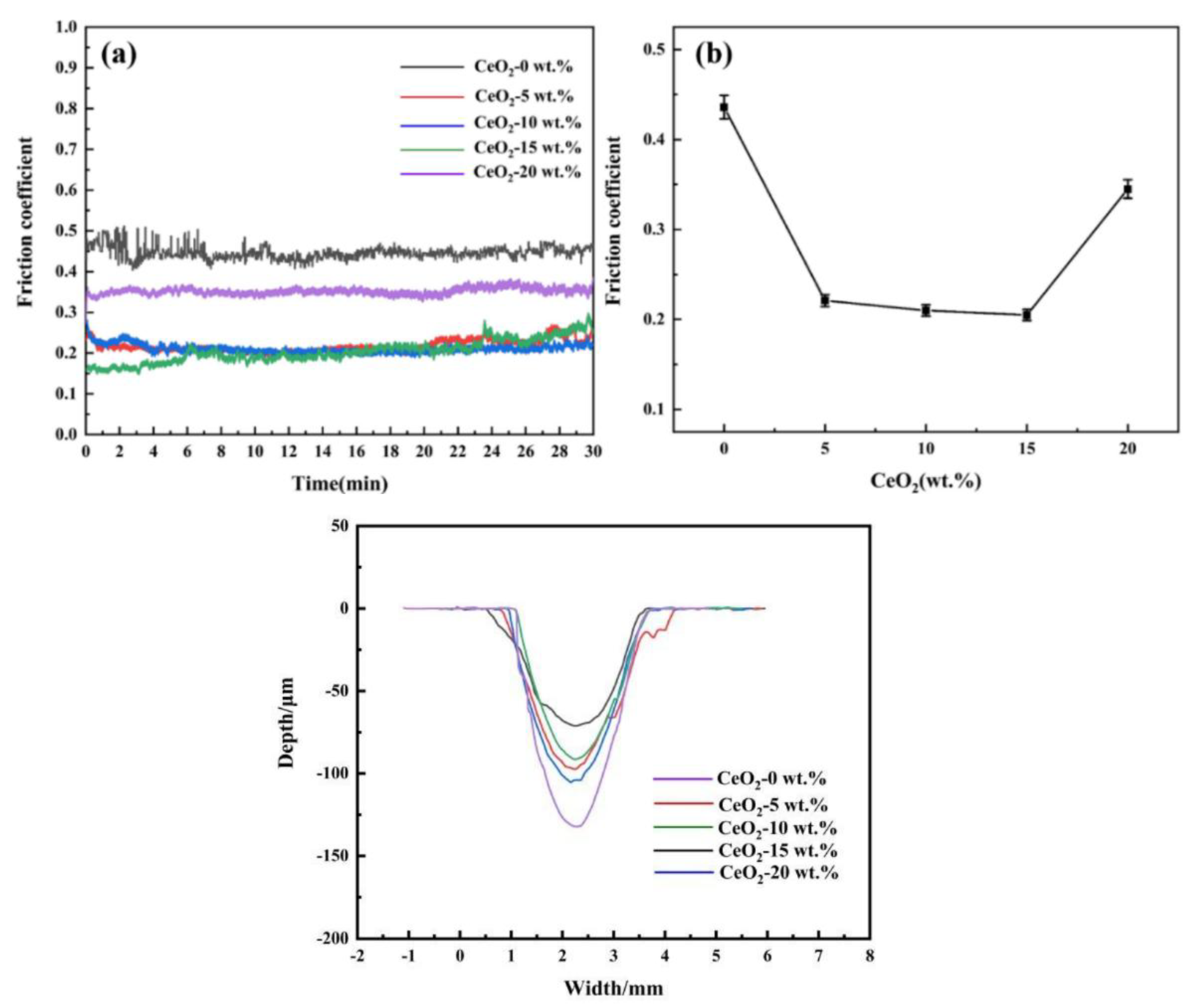
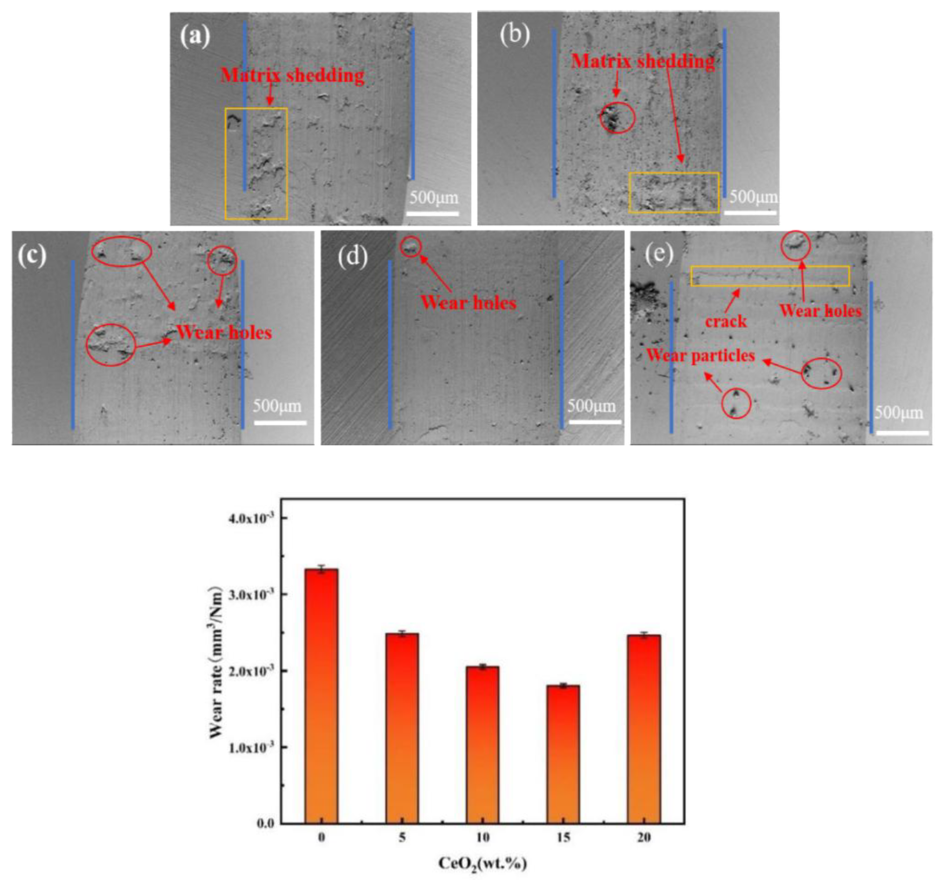
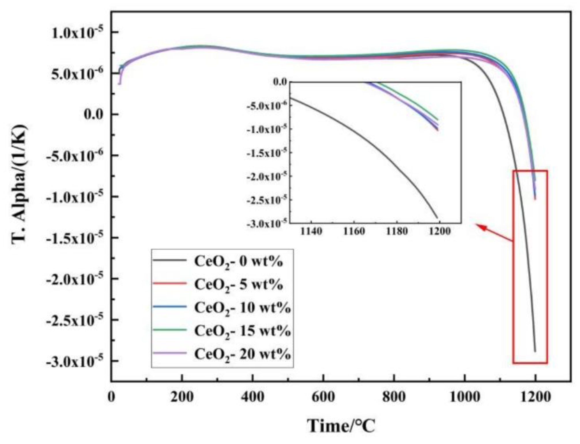
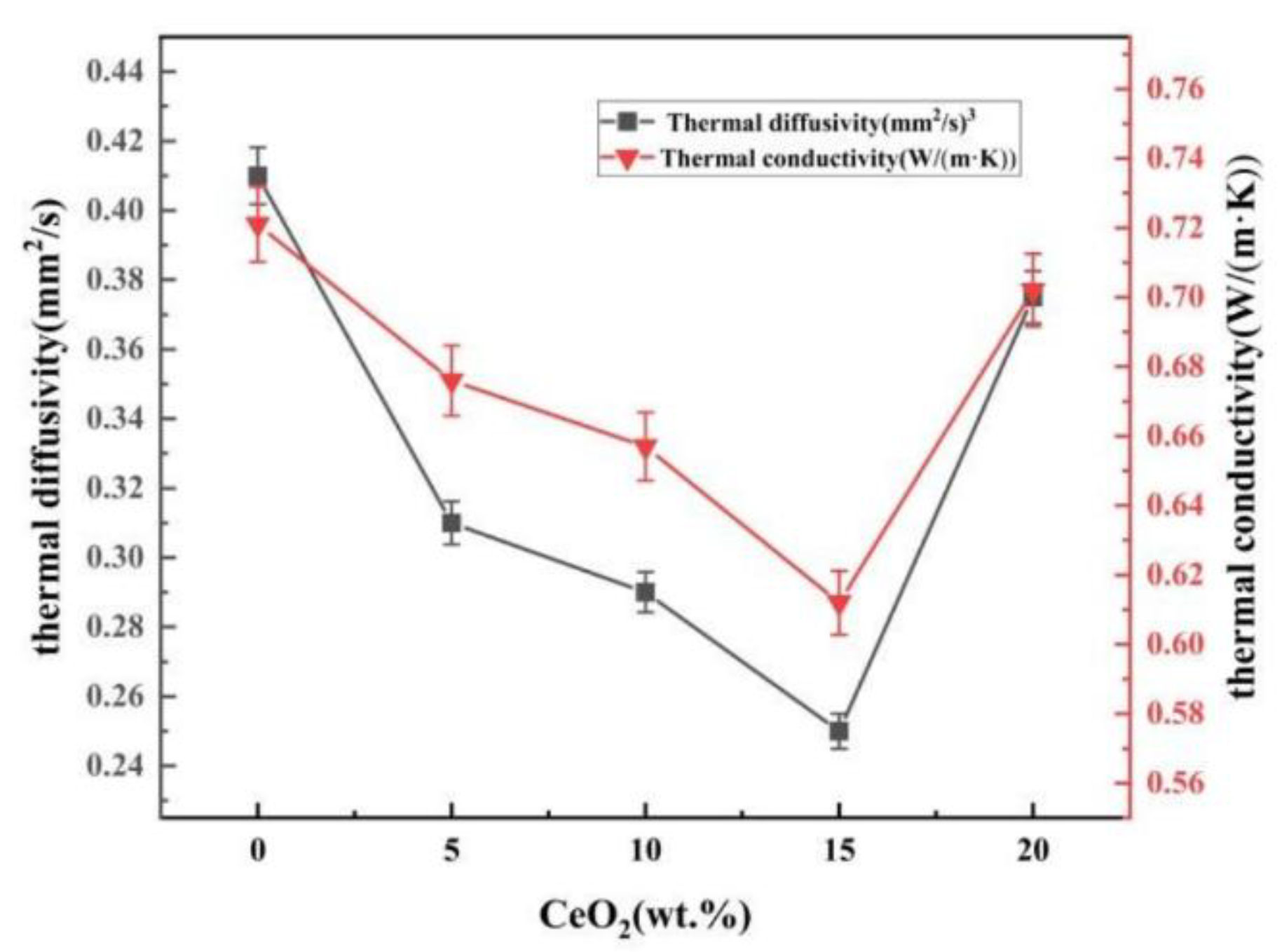
Zirconium oxide (ZrO₂) ceramics are widely used in thermal barrier coatings and high temperature structural parts due to their excellent high temperature performance and thermal insulation characteristics. However, its high temperature phase transition, thermal expansion coefficient mismatch and thermal conductivity increase limit its further application. In order to improve the comprehensive properties of ZrO₂ ceramics, the effects of different CeO₂ doping levels (0-20 wt.%) on the microstructure, mechanical properties, tribological behavior and thermophysical properties of ZrO₂ ceramics were systematically investigated. The sample was prepared by a simple and efficient method of ball milling combined with pressure-free sintering, which has simple process and low cost, and was conducive to achieving the uniformity of composition and controllable microstructure. The results showed that 15 wt.% CeO₂ was the optimal doping concentration. At this time, the density of the material was the highest, and the hardness was 310 HV₁, which was 27.64% higher than that of the undoped sample. The friction coefficient and wear rate were reduced to 0.205 and 1.81×10⁻³ mm³/N·m, respectively, showing the optimal wear resistance. At 1200 °C, the thermal expansion coefficient decreased by 72.21%, and the thermal conductivity decreased to 0.612 W/(m·K). The improved performance was mainly attributed to the solid solution enhancement of Ce⁴⁺, grain refinement and phonon scattering effect of enhanced oxygen vacancy. This study provided an important basis for optimizing the comprehensive properties of ZrO₂ ceramics by component design.

Keywords: 
;  ;  ;  ;  

1. Introduction

The thrust-to-weight ratio of an aircraft gas turbine increases with the rise in gas temperature within the turbine. This pushes the engine’s operating temperature to the limits of metallic materials. The use of low-thermal-conductivity materials allows the engine to operate at gas temperatures below the melting point of metals, thereby [1]enhancing engine efficiency and performance [1]. To mitigate this, a release layer is necessary. Zirconia (ZrO₂), characterized by its high hardness, wear resistance, thermal insulation, and corrosion resistance [2], has emerged as an ideal release layer material. Studies have further confirmed its effectiveness in inhibiting spalling and crack formation during sintering [3].
ZrO₂-based materials find widespread application in fire resistance and high-temperature protection [4,5], owing to their excellent mechanical properties (high strength and toughness) and thermal properties (high melting point, low thermal conductivity), making them a primary choice for high-temperature components. However, challenges include thermal stress arising from poor high-temperature phase stability and thermal expansion coefficient mismatch, as well as diminished thermal insulation performance due to increasing thermal conductivity at elevated temperatures [6]. To address these issues, researchers have pursued modifications such as rare earth doping (e.g., Y₂O₃, CeO₂) [7], composite ceramics (e.g., ZrO₂-Al₂O₃), and nanostructure design, aiming to enhance thermal stability and lower thermal conductivity.
Among these approaches, CeO₂ doping has been established as an effective modification method, demonstrating three key advantages: (1) Significantly enhancing high-temperature phase stability by delaying the tetragonal-to-monoclinic phase transition [7]; (2) Optimizing the thermal expansion coefficient to mitigate thermal stress; (3) Suppressing the temperature-dependent rise in thermal conductivity. Compared to conventional Y₂O₃-stabilized ZrO₂, CeO₂-ZrO₂ exhibits superior thermal stability, fracture toughness, and oxidation resistance [8]. These properties endow it with significant application potential for graphite boat bulk ceramics and thermal barrier bulk ceramics.
This study investigates the effects of CeO₂ doping on the physical properties, tribological behavior, and thermal characteristics of zirconia ceramics. Specimens with varying CeO₂ content (xCe-ZrO₂, x= 0, 5, 10, 15, 20 wt.%) were synthesized via ball milling, dry pressing, and atmospheric sintering. An optimal CeO₂ doping concentration was established, achieving synergistic enhancement of densification, hardness, wear resistance, and thermal stability for targeted industrial applications.

2. Experimental Procedure

2.1. Materials

The primary materials used in this study were ZrO2 powder (AR, 10-20 μm, Shanghai Yaoyi Alloy Materials Co., Ltd.), CeO2 powder (AR, 5μm, Shanghai Yaoyi Alloy Materials Co., Ltd.), anhydrous ethanol (purity>99.7%, Xilong Scientific Co., Ltd.), and polyacrylic acid (30% solid content, Shanghai Macklin Biochemical Technology Co., Ltd.).

2.2. Sample Preparation

In this experiment, ZrO2 was used as the matrix material, and rare earth doped ZrO2 ceramics were prepared by adding different contents of CeO2 (see Table 1). The specific process is as follows: (1) ZrO2 and CeO2 powders were weighed according to the ratio of Table 1, and ZrO2 grinding balls were added at a ball-to-powder ratio of 5:1, and ball milling was performed using anhydrous ethanol as the medium and polyacrylic acid (30 wt.%) as the binder; (2) The composite powder was obtained by vacuum drying, grinding and sieving of ball abrasive; (3) Cylindrical green body was prepared by unidirectional molding with cemented carbide mold (YP-20T hydraulic press, holding pressure for 60 s); (4) Sintering in air atmosphere in KSL-1700X box furnace: first, the organic matter was removed by rising from 3°C/min to 330 °C for 300 min, then rising from 5 °C/min to 1600 °C for 600 mins, and finally cooling with the furnace. The sintering parameter diagram of this work is shown in Figure 1.

2.3. Characterization

The phase composition of ceramic materials was analyzed by XRD. The X-ray diffraction analysis model used in this experiment was Empyream. The setting parameters of the equipment during the analysis were as follows: the scanning Angle was 10-90°, and the scanning speed was 4 °/min. Tube voltage: 40 KV, tube current: 40 mA.
The model of the scanning electron microscope used is MLA-650. It is equipped with energy dispersive spectroscopy (EDS). In order to ensure the clarity of the image, the polished sample is subjected to gold spraying treatment.
In this experiment, the density of rare earth-doped ZrO2 ceramic materials was determined based on Archimedes’ principle. The experiment used the multi-functional electronic hydrometer AU-600ME to weigh the mass of the samples in the air and in the water. Calculate the density of the sample according to formula (1) [9]:
D 1 = m 2 ρ m 1 m 2
In formula (1): D1 is the density of the sample; m1 is the mass of the sample in the air, g; m2 is the mass of the sample in water, g; ρ is the density of water at room temperature, g/cm3 (usually 1g/cm3).
According to formula (2) to calculate the relative density of the sample, and then understand the porosity of ceramic materials[10]:
d = D 1 D 2 × 100 %
In equation (2): d is the relative density of the sample, %; D1 is the density of the sample, g/cm3; D2 is the theoretical density of the sample, g/cm3.
The hardness value of rare earth doped ZrO2 ceramic materials was determined by using the digital Vickers hardness tester THV-50 MDX. The parameters were set as pressure load of 1 kg and holding time of 10 s. The value was calculated according to formula (3) [11]:
HV = 0.891 P d v 2
In formula (3): HV is Vickers hardness value, kg/mm2; P is the pressure load, kg;dv is the length of the indentation diagonal, mm.
The HSR-2M reciprocating friction and wear tester was used to determine the friction and wear characteristics of rare earth doped ZrO2 ceramic materials. The loading force is 10 N, the frequency is 4 Hz, the total friction time is 8 min, and the one-way round-trip length of friction is 5 mm.
At the end of the experiment, the 2D profiles of the wear scars on the surface of the material were measured by a three-dimensional profiler model NanoMap 500LS, and the depth and width of the wear scars were determined. The data obtained can be used to calculate the wear rate of rare earth doped ZrO2 ceramic materials, and the tribological properties of rare earth doped ZrO2 ceramic materials are further analyzed and evaluated by the wear rate. In general, the wear rate is calculated according to formula(4) [12]:
K V = S × l N × L
KV is the wear rate, mm3/Nm; s is the cross-sectional area of the wear scar, mm2; l is the length of the wear scar, mm; n is the load force in the friction and wear experiment, N; L is the friction stroke in the friction and wear experiment, m. In this experiment, L=9.6 m, N=10 N, l=5 mm.
The thermal diffusivity and specific heat capacity of the bulk ceramic were measured by laser thermal conductivity meter (LFA 42). The density of the bulk ceramics was measured by Archimedes drainage method. The test temperature was 1100°C. Finally, the thermal conductivity of the bulk ceramic was obtained by equations (5) and (6) [13,14]:
λ=αCp·ρ
Cp=69.2+4.3×10⁻³T-1.3×10⁶T-2
Here, CP is the specific heat capacity. ρ is the density of the bulk ceramic, which is determined by Archimedes method. α is the thermal diffusion coefficient of the material. λ is the thermal conductivity of the material.
The linear coefficient of thermal expansion (CTE) in the range of 25-1200 °C was measured by a thermal dilatometer (TMA 403 F3, NETZSCH, Germany). The sample was heated from room temperature (T0 = 25 °C) to T = 1200 °C at a heating rate of 0.1 °C/s. CTE was calculated by formula (7) [15] :
α = Δ L L 0 × Δ L
where, α is the linear expansion coefficient (unit: K−1); Δ L= L − L: length change caused by temperature change (unit: mm); L0 is the original length at the initial temperature (the unit is consistent with ΔL); Δ T = T − T0: temperature change (unit: K).

3. Results and Discussion

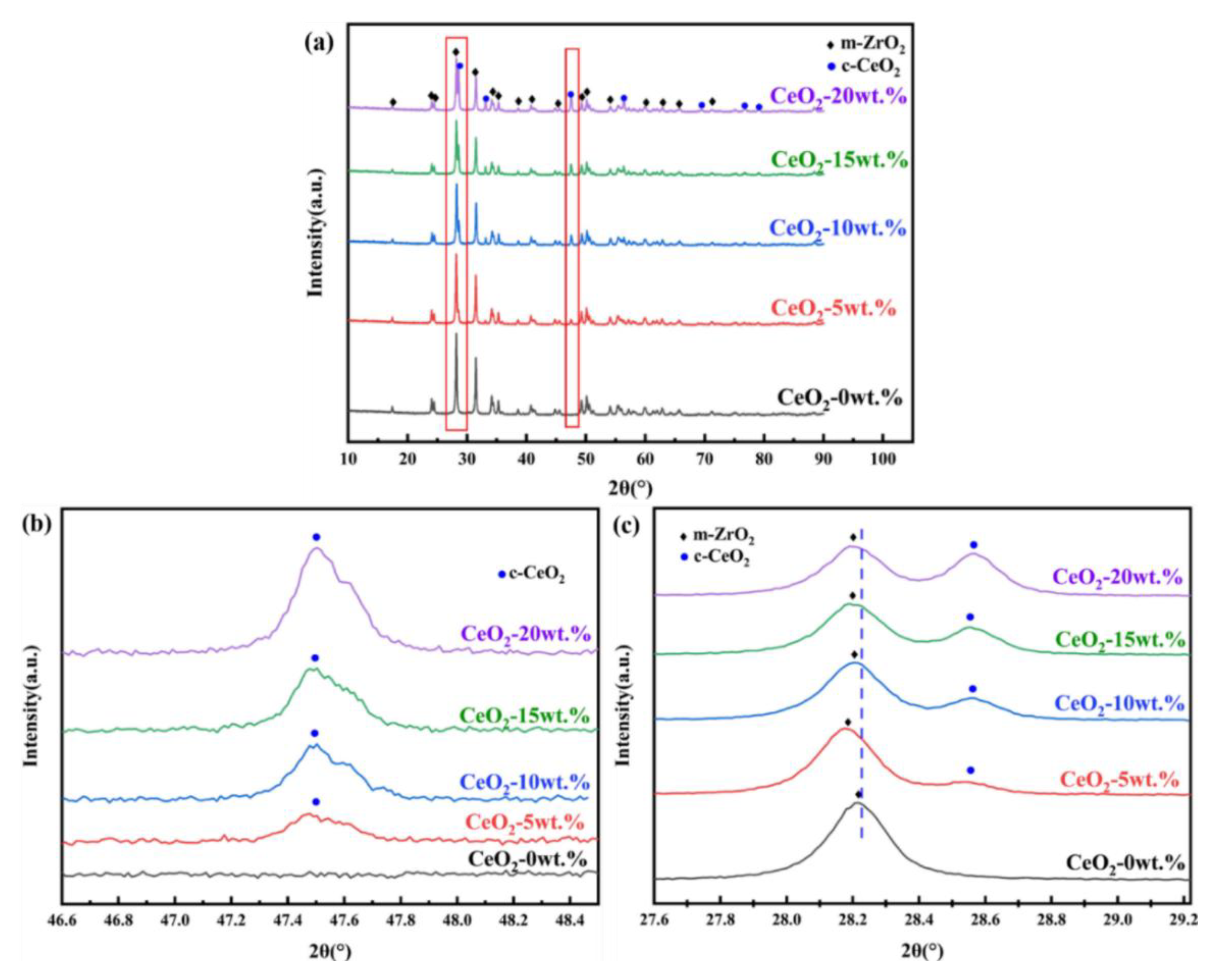
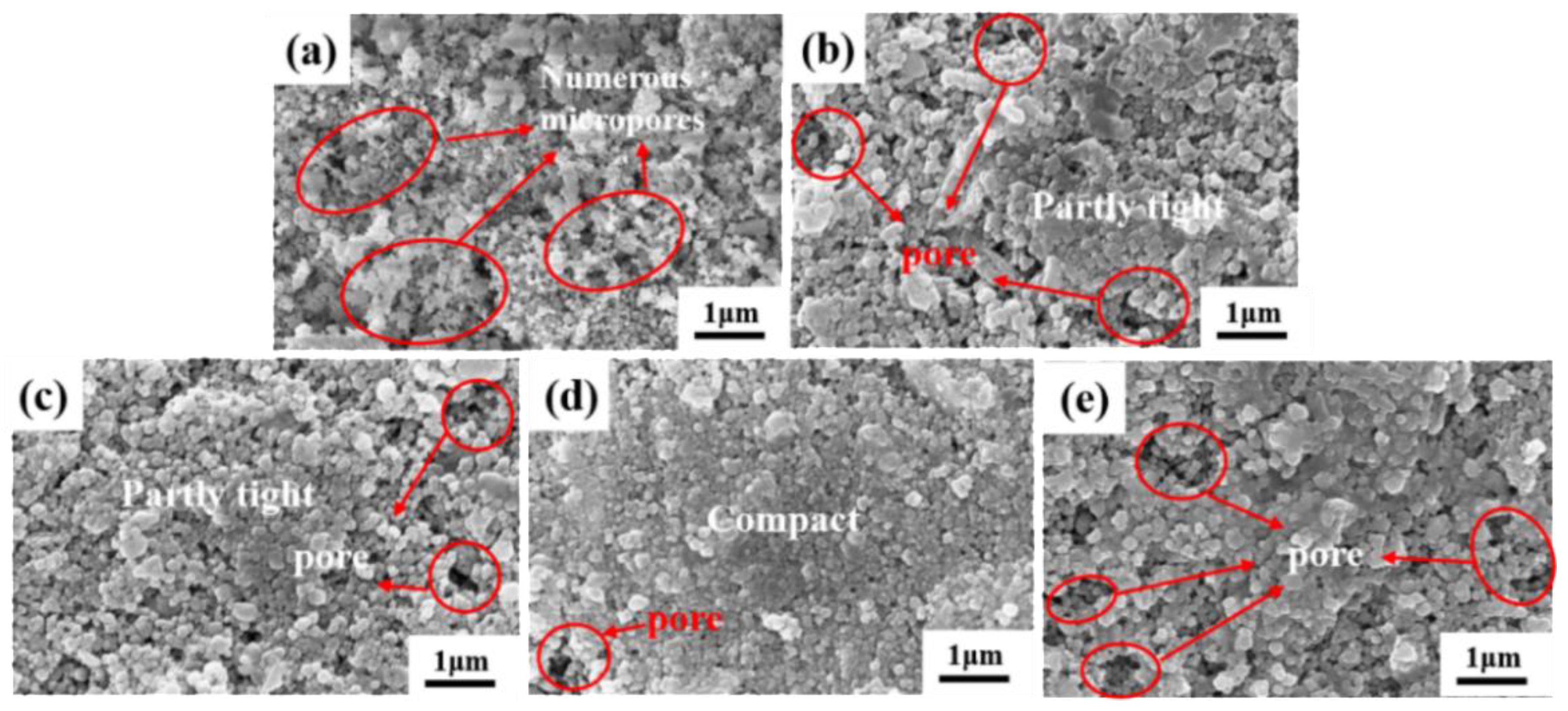
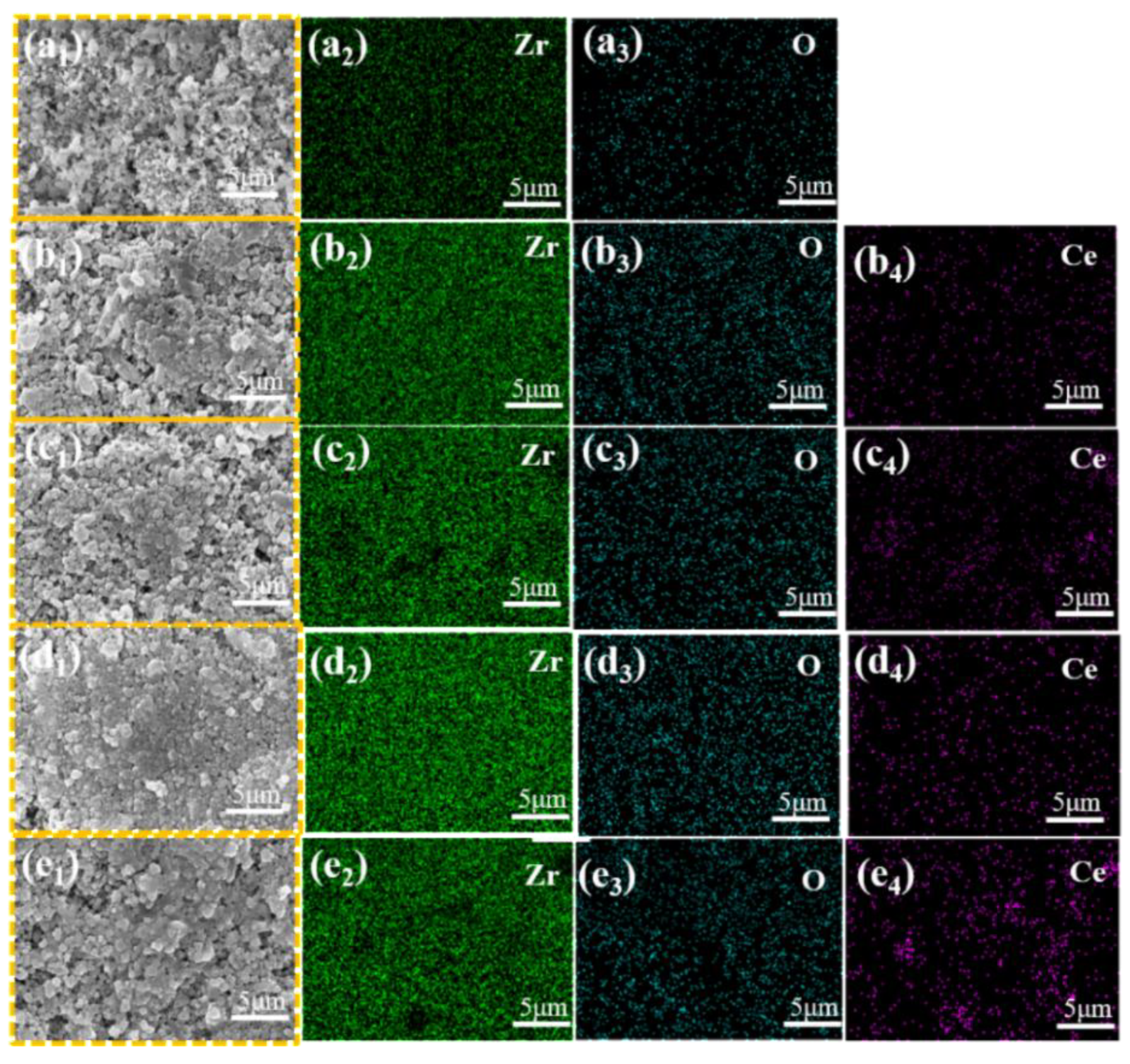
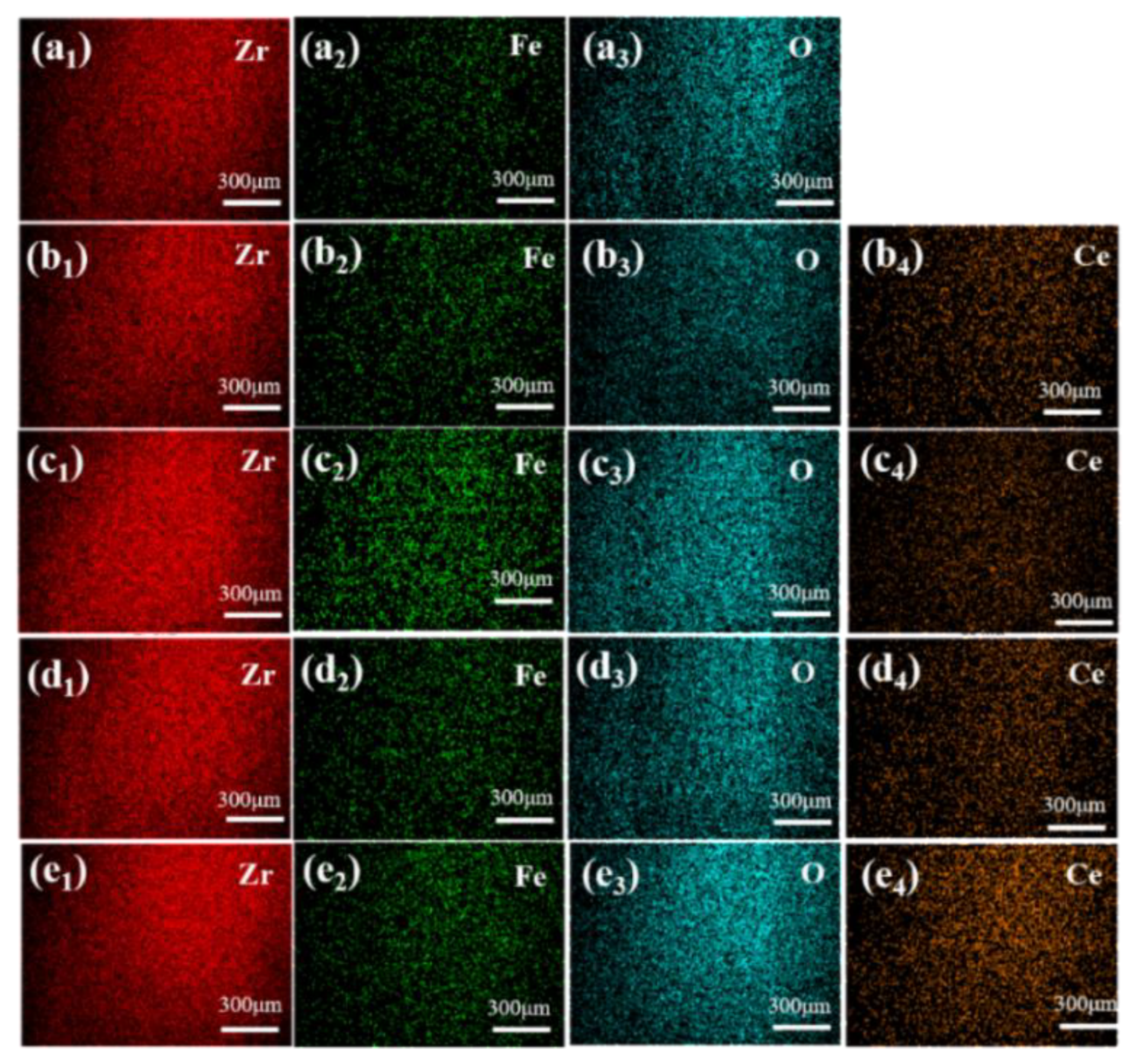
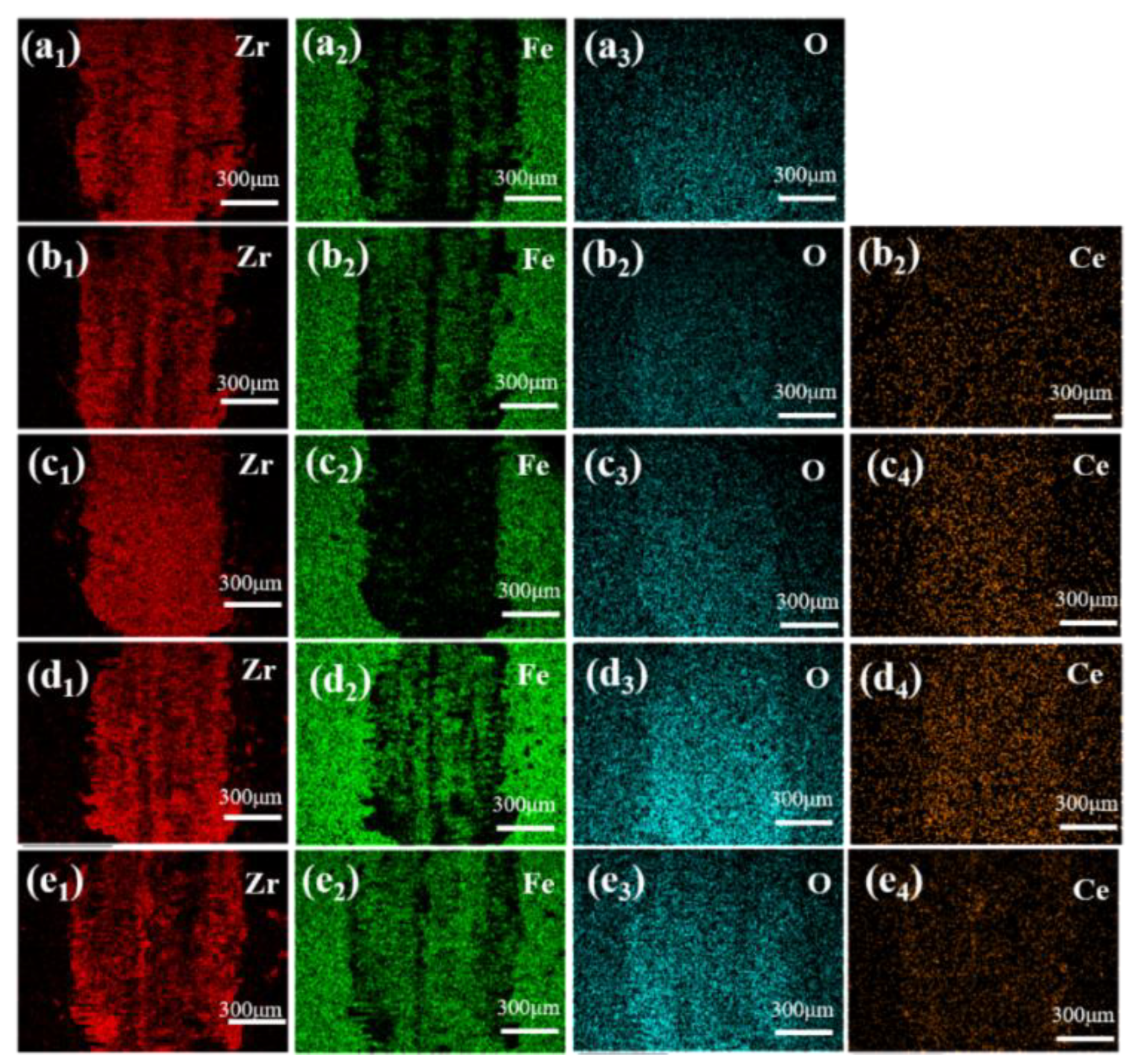
3.1. Phase Composition and Microstructure

Figure 1 presents the XRD patterns and corresponding local magnification for CeO2 doped ZrO₂ ceramics with varying CeO₂ contents after sintering. Comparison with the reference ZrO₂ pattern revealed the emergence of new diffraction peaks at approximately 28.6°, 33.2°, 47.7°, and 56.2°. The intensity of these new peaks was observed to increase with increasing CeO₂ content. Identification using the relevant PDF card confirmed that these peaks primarily correspond to CeO₂. While ZrO₂ exhibits a monoclinic crystal structure at room temperature, CeO₂ crystallizes in the cubic fluorite structure. When the doping concentration of CeO₂ exceeds its solid solubility limit in the ZrO₂ lattice, the excess CeO₂ precipitates as a distinct secondary phase. This phase separation gives rise to the distinct diffraction peaks observed, which differ from those of the primary ZrO₂ matrix phase. This finding aligns with the observations reported by Karem et al. [16]. Furthermore, Figure 1(c) indicates a shift of the characteristic ZrO₂ peak located near 28.2° towards lower diffraction angles. This shift is attributed to the substitution of Zr⁴⁺ ions (ionic radius≈0.84 Å for coordination number 8) by the larger Ce⁴⁺ ions (ionic radius≈0.97 Å for coordination number 8). This ionic substitution leads to an expansion of the unit cell parameters of the ZrO₂-based solid solution. According to Bragg’s law (nλ = 2 d sinθ, where d is the interplanar spacing, θ is the diffraction angle, λ is the X-ray wavelength, and n is the diffraction order), an increase in d results in a decrease in sinθ (and consequently θ) for a given reflection, manifesting as a peak shift to lower angles [17,18].
Figure 2 and Figure 3 present the SEM and EDS, respectively, for ZrO₂ ceramic materials doped with varying CeO₂ contents. From the SEM images, it can be observed that as the CeO2 content increases, the grain size gradually decreases. However, when the CeO₂ doping level exceeds 15 wt.%, abnormal grain coarsening occurs. This phenomenon can be attributed to two main factors. Firstly, the agglomeration of CeO₂ nanoparticles reduces the density of effective nucleation sites, promoting grain coalescence and growth[19]. Secondly, the high concentration of CeO₂ alter sintering behavior, enhancing grain boundary diffusion and thereby facilitating grain coarsening. The residual sintering activity or presence of a local liquid phase contributes to the observed gradual increase in grain size[20]. Correspondingly, the pore number density (or porosity) decreases within the 0-15 wt.% CeO₂ range, indicating that moderate doping effectively improves microstructural homogeneity and reduces defect density. Conversely, as the CeO₂ content increases beyond 15 wt.%, the pore number density increases and pores become more widely distributed. This deterioration is attributed to structural inhomogeneities arising from incomplete mass transfer during sintering, particle coalescence issues, and the formation of agglomerates or secondary phases due to the excess dopant, all of which contribute to increased porosity[21]. The EDS elemental mappings in Figure 3 corroborate these findings. The intensity of the Ce4+ signal progressively increases with CeO₂ doping level. Notably, Figure 3(e4) reveals localized Ce4+ agglomeration/clustering at higher doping concentrations (20 wt.%), directly confirming that excessive CeO₂ addition promotes particle agglomeration. The O element distribution is uniform across all samples, consistent with the oxide nature of the starting materials. Significantly, the 15Ce-ZrO₂ sample exhibits the most homogeneous distribution of Zr4+, Ce4+, and O2- on the material surface, corresponding to its optimal microstructure.

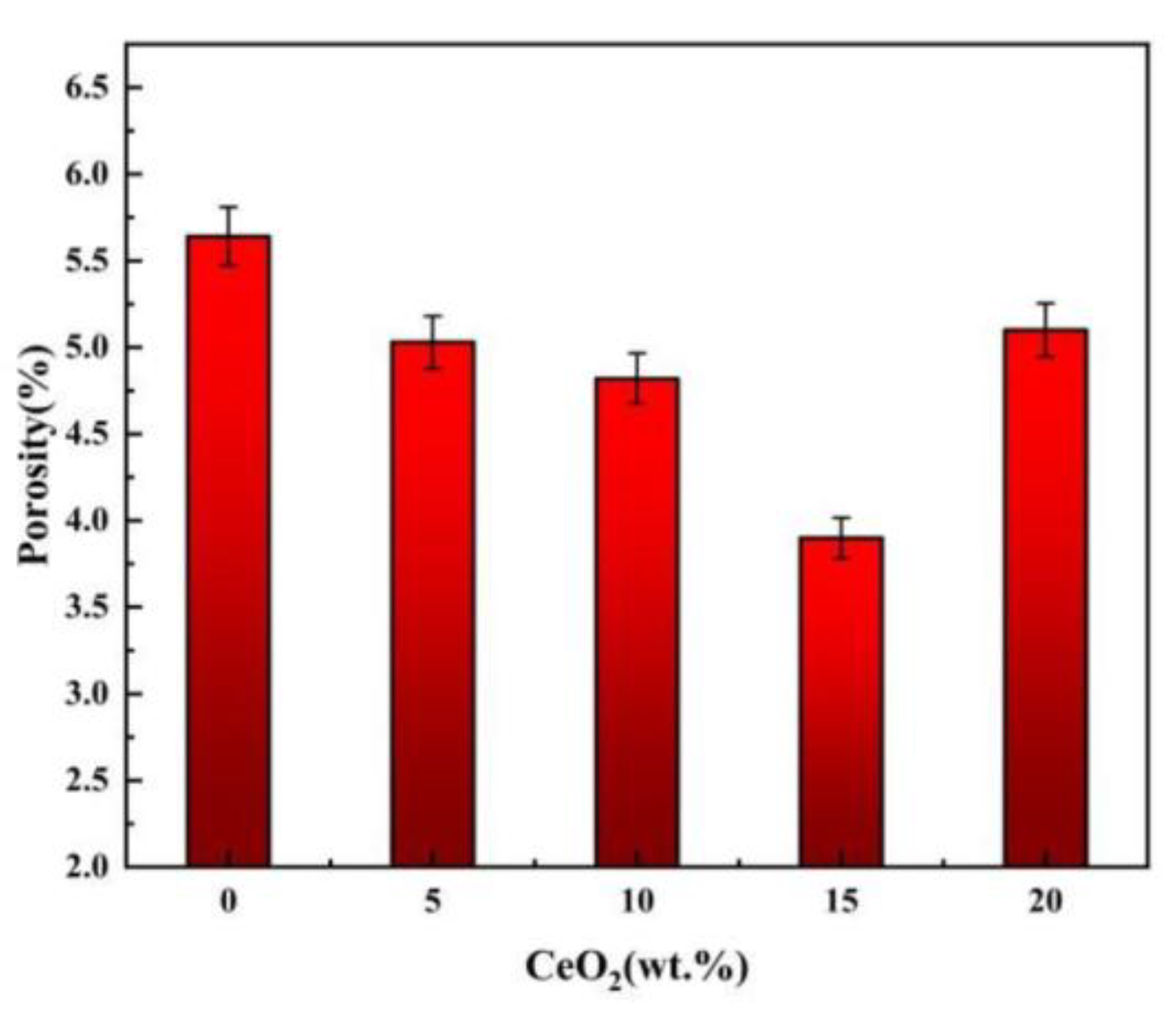
3.2. Density, Porosity and Relative Density

Figure 4 presents the porosity of ZrO₂ ceramics doped with varying CeO₂ contents, Figure 5 presents the bulk density and relative density of ZrO₂ ceramics doped with varying CeO₂ contents. Analysis combining Figure 4 (porosity) and Figure 5 reveals that both the pore number density (or porosity) of the Ce-doped ZrO₂ system exhibit a non-monotonic trend, initially decreasing and subsequently increasing with increasing CeO₂ content. The reduction in grain size observed with moderate CeO₂ doping (0-15 wt.%) is primarily attributed to grain boundary pinning effects. CeO₂ additions interact with the ZrO₂ matrix grain boundaries, effectively inhibiting grain boundary migration kinetics by altering the grain boundary chemical potential, thereby suppressing grain growth [22]. Furthermore, the uniform distribution of CeO₂ facilitates microstructural refinement through mechanisms including second-phase dispersion strengthening, grain boundary segregation, and heterogeneous nucleation, leading to reduced porosity and finer grains[23,24,25]. As shown, the bulk density increases with increasing CeO₂ content. Notably, the rate of density increase diminishes when the CeO₂ content reaches 15 wt.%. In contrast, the relative density exhibits a non-monotonic trend, initially increasing to a maximum of 96.1% at 15 wt.% CeO₂, and then decreasing at higher dopant levels. The initial increase in relative density (up to 15 wt.% CeO₂) can be attributed to two primary factors: (1) Lattice distortion: The significant difference in ionic radius between Ce⁴⁺ (≈0.97 Å for CN=8) and Zr⁴⁺ (≈0.84 Å for CN=8) induces substantial lattice distortion upon substitution into the ZrO₂ lattice. This distortion can promote densification mechanisms during sintering[20,26]. (2) Reduced porosity: As discussed in conjunction with Figure 4, the number density of pores decreases within this doping range, directly contributing to the higher relative density. However, when the CeO₂ content exceeds 15 wt.%, the relative density declines. This deterioration is mainly due to diminished grain boundary pinning and impeded densification. Firstly, excess CeO₂ can compromise its effectiveness as a grain boundary pinning agent. This reduction in pinning force facilitates abnormal grain growth, leading to the development of larger intergranular pores/voids[27,28]. Secondly, high CeO₂ concentrations increase the residual oxygen content within the material, which can hinder the final stages of sintering densification. Furthermore, at elevated temperatures, excess CeO₂ promote the coalescence of micropores, further reducing the relative density[28].

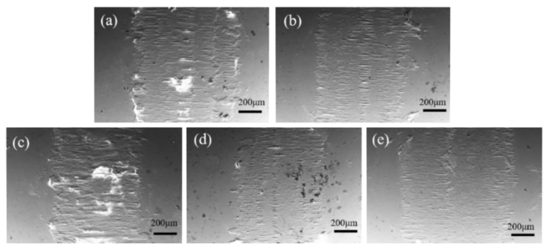
3.3. Hardness, Friction and Wear Performance

Figure 6 presents the Vickers hardness (HV₁) of ZrO₂ ceramics as a function of CeO₂ doping content. The hardness exhibits a non-monotonic dependence on dopant concentration, initially increasing to a maximum value of 310 HV₁ at 15 wt.% CeO₂ representing a 27.64% enhancement compared to undoped ZrO₂ followed by a decrease at higher doping levels. The mechanisms for hardness enhancement (≤15 wt.% CeO₂) contain second-phase dispersion strengthening and grain refinement. Firstly, moderate CeO₂ doping effectively inhibits grain growth (as evidenced in Figure 2), leading to grain refinement. This increases the density of grain boundaries, which act as barriers to dislocation motion[29,30]. Secondly, the dissolved Ce⁴⁺ ions form a supersaturated solid solution within the ZrO₂ lattice. The associated lattice strain fields impede dislocation glide, enhancing hardness[27]. Thirdly, the finely dispersed CeO₂ particles exert a pinning effect on grain boundaries, further stabilizing the refined microstructure and contributing to strengthening[27]. The mechanisms for hardness reduction (>15 wt.% CeO₂) contain phase separation and stress concentration, and increased porosity. Firstly, the excessive CeO₂ exceeds its solid solubility limit, leading to secondary phase formation (CeO₂-rich precipitates). These phases induce stress concentrations at grain boundaries due to thermal expansion mismatch and/or elastic modulus differences, facilitating crack initiation and reducing macroscopic hardness[31]. Secondly, as shown in Figure 2 and Figure 4, the porosity significantly increases beyond 15 wt.% CeO₂. These pores act as stress concentrators and preferential sites for crack propagation, thereby diminishing the material’s load-bearing capacity and measured hardness[32].
Figure 7 presents the friction coefficient curves, average friction coefficients, and corresponding 2D wear scar profiles for ZrO₂ ceramics doped with varying CeO₂ contents. Complementary quantitative wear scar dimensions (width and depth) are provided in Table 2. For undoped ZrO₂ (Figure 7a), it exhibits a prolonged friction coefficient stabilization period. This instability primarily arises from abrasive wear induced by surface micro-asperities and adhesive wear due to the absence of a self-lubricating phase[33]. For CeO₂-doped samples, it demonstrate significantly improved tribological performance. The 15Ce-ZrO₂ sample achieves the lowest average friction coefficient (0.205, representing a 52.98% reduction compared to undoped ZrO₂) and the shortest stabilization time (4 mins). This enhancement is attributed to a synergistic effect. Firstly, CeO₂ effectively seals intergranular defects and reduces surface roughness. Secondly, the enhanced hardness via solid solution strengthening and grain boundary pinning improves resistance to deformation and wear[20,25]. Thirdly, the inherent layered structure of CeO₂ facilitates the development of a low-shear-strength lubricating transfer film at the sliding interface[20,25]. For excessive doping (>15 wt.% CeO₂), the performance deteriorates due to two reasons. On the one hand, the agglomerated CeO₂ particles detach, forming hard abrasive debris that accelerates wear. On the other hand, the reduced density and hardness diminish the wear resistance. Through wear scar analysis, the 15Ce-ZrO₂ sample exhibits optimal wear resistance, with the smallest wear scar dimensions (width: 2.44 mm, depth: 71.17 μm; representing a 40.2% reduction in depth compared to undoped ZrO₂). This is primarily a consequence of grain refinement and increased density, which reduce microcracking and the likelihood of third-body abrasive formation during sliding[34]. Conversely, the 20Ce-ZrO₂ sample shows a significant rebound in wear depth (105.18 μm), directly correlating with its degraded density and hardness[33]. Optimal CeO₂ doping (15 wt.%) synergistically enhances the tribological properties of ZrO₂ ceramics through intergranular defect healing, microstructural strengthening, and effective tribo-film formation, minimizing friction and wear[25,33,35].
Figure 8 and Figure 9 present the SEM morphology of wear scars, corresponding EDS analysis, and wear rate data for ZrO₂ ceramics with varying CeO₂ doping contents. SEM wear scar analysis (Figure 8), All samples exhibit wear scars characterized by parallel grooves aligned with the sliding direction, accompanied by brittle delamination pits and debris accumulation. As CeO₂ content increases from 0 to 15 wt.%, the severity of wear scars, microcracking density, and debris detachment progressively decrease. The 15Ce-ZrO₂ sample demonstrates the smoothest wear surface. This is attributed to CeO₂-induced grain refinement, microstructural homogenization, and defect density reduction[36]. Furthermore, the well-distributed CeO₂ at grain boundaries effectively impedes dislocation motion and inhibits crack propagation, enhancing cohesive strength[20]. Conversely, the excessive doping (20 wt.% CeO₂) promotes CeO₂ agglomeration, increased porosity and reduced hardness. These factors collectively lead to prominent transverse cracking and extensive abrasive debris generation within the wear scar[32]. From Figure 9, the wear rate decreases significantly from 3.33 × 10⁻³ mm³/(N·m) for undoped ZrO₂ to 1.81 × 10⁻³ mm³/(N·m) for 15Ce-ZrO₂, representing a 45.65% reduction. This enhancement correlates with solid solution strengthening and grain boundary pinning, which simultaneously elevate density and hardness. The 20Ce-ZrO₂ sample exhibits a rebounded wear rate of 2.46 × 10⁻³ mm³/(N·m), primarily driven by grain boundary stress concentration (due to agglomeration/secondary phases) and elevated porosity[32].
Figure 10 and Figure 11 present the SEM morphology and corresponding EDS elemental mappings of worn surfaces following tribological testing. From wear scar morphology, all samples exhibit surfaces dominated by parallel grooves aligned with the sliding direction, accompanied by lamellar delamination debris accumulation. The 15Ce-ZrO₂ sample demonstrates the narrowest/shallowest wear track and minimal debris accumulation. This correlates with grain boundary strengthening via CeO₂ segregation/pinning to form a coherent, low-shear-strength lubricating tribo-film. Distinct Ce/Zr signals (co-localized with Fe/O) confirm adhesive material transfer from the counter-body under shear stress. However, excessive CeO₂ (>15 wt.%) promotes hard phase agglomeration, which acts as stress concentrators. This, coupled with reduced hardness and increased porosity, exacerbates abrasive wear and surface fracture, leading to accelerated material removal.

3.4. Thermal Properties

The coefficient of thermal expansion (CTE) is a critical performance parameter for zirconia ceramics, profoundly influencing their thermo-mechanical stability, manufacturability, and service performance in applications involving thermal cycling[37]. In Figure 12, both undoped ZrO₂ and CeO₂-doped ZrO₂ exhibit rapid expansion below ~250 °C (CTE: ~8.818 × 10⁻⁶ K⁻¹), followed by a gradual decline to 6.68–7.20 × 10⁻⁶ K⁻¹ at 250–950 °C. The high congruence of CTE curves across all compositions in this range confirms that CeO₂ doping preserves the intrinsic crystallographic stability of the ZrO₂ matrix. At temperature above 950 °C, the undoped ZrO₂ undergoes abrupt thermal contraction, associated with the deleterious tetragonal (t) → monoclinic (m) phase transformation. CeO₂ doping delays the onset of contraction to ≥1000°C. Local magnification reveals drastically suppressed contraction magnitude in Ce-doped systems at 1120–1200 °C. Specifically, the 15Ce-ZrO₂ achieves a 72.21% reduction in absolute CTE value at 1200 °C versus undoped ZrO₂, demonstrating effective inhibition of high-temperature shrinkage. This significantly mitigates thermally induced mismatch stresses. The mechanism of shrinkage suppression was Ce⁴⁺ substitution (r = 0.97 Å, CN=8) for Zr⁴⁺ (r = 0.84 Å, CN=8) within the Zr₁-ₓCeₓO₂ solid solution. Firstly, the dilatational lattice strain from the larger Ce⁴⁺ ion expands the unit cell and reconstructs local stress fields. This stabilizes the tetragonal/cubic phases by suppressing the t→m martensitic transformation through compressive constraints[15]. Secondly, the charge compensation for Ce⁴⁺ incorporation generates oxygen vacancies. These vacancies preferentially order along the c-axis, increasing the activation energy barrier for the reconstructive t→m transformation[38].
The thermal conductivity of ceramics is predominantly governed by phonon-mediated heat transfer[39,40,41,42]. Oxygen vacancies constitute a potent source of phonon scattering, arising from the associated mass defect and the disruption of interatomic bonding[43]. In ZrO₂, the characteristically low thermal conductivity is attributed to lattice distortion and phonon scattering intensified by oxygen vacancies. These mechanisms reduce thermal diffusivity, rendering ZrO₂ an effective thermal barrier material[37]. Figure 13 presents the thermal conductivity and thermal diffusivity of CeO₂-doped ZrO₂ ceramics measured at 1100°C. Notably, both properties exhibit a non-monotonic dependence on CeO₂ content, initially decreasing before increasing. The minimum values, observed for 15Ce-ZrO₂, are 0.25 mm²/s for thermal diffusivity and 0.612 W/(m·K) for thermal conductivity. These minima represent reductions of 39.02% and 15.12%, respectively, compared to undoped ZrO₂. This minimum in thermal transport properties at intermediate CeO₂ concentrations is rationalized by two primary mechanisms. Firstly, the substitution of Zr⁴⁺ by Ce⁴⁺ induces lattice strain and local stress fields, enhancing phonon scattering. Secondly, under high-temperature sintering or reducing conditions, the partial reduction of Ce⁴⁺ to Ce³⁺ occurs to maintain charge neutrality. This reduction generates oxygen vacancies[44]. These vacancies act as additional phonon scattering centers, further reducing the phonon mean free path and consequently the thermal conductivity. However, the thermal conductivity of 20Ce-ZrO2 materials increases. This is due to that at 1100 °C, high concentrations of CeO2 can stabilize high-temperature phases (such as tetragonal or cubic phases). The thermal conductivity of these high-temperature chambers is usually higher than that of the monoclinic phase, resulting in an increase in thermal conductivity. In addition, it also be due to the uneven grain growth of 20Ce-ZrO2, resulting in a large number of pores, which will seriously affect or even interrupt the phonon transmission[45].

4. Conclusions

This study systematically investigated the impact of CeO₂ doping levels on ZrO₂’s properties. XRD confirmed Ce⁴⁺ substitution for Zr⁴⁺, forming a cubic phase with increasing intensity and causing lattice expansion. The SEM revealed optimal 15 wt.% doping reduced porosity via grain refinement and segregation, while excess doping (>15 wt.%) caused CeO₂ agglomeration, phase separation, grain coarsening, and increased porosity. The relative density peaked at 96.1% and hardness maximized at 310 HV1 (28% increase vs. undoped) at 15 wt.%, attributed to grain refinement, solid solution strengthening, and grain boundary pinning. The excess doping reduced hardness due to porosity and stress concentrations. Friction and wear performance optimized at 15 wt.% CeO₂: average coefficient dropped 53% to 0.205, wear rate minimized at 1.81 × 10⁻³ mm³/N·m, and wear scar depth decreased 40%. This resulted from inhibited abrasive particle release and crack propagation via densification and grain boundary homogenization. Thermal stability significantly improved: the 15 wt.% sample exhibited a 72.2% reduction in thermal expansion coefficient magnitude at 1200 °C and increased thermal shrinkage onset temperature by 50 °C (to 1000 °C). Its thermal conductivity decreased 15.1% to 0.612 W/(m·K) due to suppressed phase transition and enhanced phonon scattering from oxygen vacancies. Optimal 15 wt.% doping enhances ZrO₂ properties synergistically, while excess doping degrades performance

Author Contributions

Conceptualization, F.C. and T.Z.; methodology, F.C. and T.Z.; formal analysis, F.C., T.Z., Y.L. and X.Z.; investigation F.C., T.Z., Y.L. and X.Z.; resources Y.Y. and H.C.; data curation, F.C.; writing-review and editing, F.C.; supervision Y.Y. and H.C.; All authors have read and agreed to the published version of the manuscript.

Acknowledgments

The work was financially supported by the Key research and development project of Jiangxi Province (20224BBE510).

Data Availability Statement

The data presented in this study are available on request from the corresponding author. The data are not publicly available due to privacy restrictions.

Conflicts of Interest

The authors declare that they have no known competing financial interests or personal relationships that could have appeared to influence the work reported in this paper.

References

  1. Wang, Z.; Du, L.Z. Stabilization of a novel mixed solution precursor used for preparing YSZ abradable sealing coatings. Colloid Surf A 2024, 562, 354–360. [Google Scholar] [CrossRef]
  2. He, Y.; Zhang, S.; He, Y.; Song, R.; Zhang, Z.; Liu, B.; Li, H.; Shangguan, J. Effects of yttrium-stabilized zirconia (different yttrium content) doping on the structure, corrosion resistance and wear resistance of Ni-P electroless coating. Colloid Surf A 2022, 654, 130059. [Google Scholar] [CrossRef]
  3. Wang, S.L.; Li, K.Z.; Li, H.J.; Zhang, Y.L.; Wang, Y.J. Effects of microstructures on the ablation behaviors of ZrC deposited by CVD. Surf Coat Tech. 2024, 240, 450–455. [Google Scholar] [CrossRef]
  4. Reddy Channu, V.S.; Kalluru, R.R.; Schlesinger, M.; Mehring, M.; Holze, R. Synthesis and characterization of ZrO2 nanoparticles for optical and electrochemical applications. Colloid Surf A 2011, 386, 151–157. [Google Scholar] [CrossRef]
  5. Liu, B.X.; Lin, X.J.; Zhu, L.Y.; Wang, X.Q.; Xu, D. Fabrication of calcium zirconate fibers by the solgel method. Ceram Int. 2014, 40, 12525–12531. [Google Scholar] [CrossRef]
  6. Wang, J.; Li, H.P.; Stevens, R. Hafnia and hafnia-toughened ceramics. J. Mater. Sci. 1992, 27, 5397–5430. [Google Scholar] [CrossRef]
  7. Lee, H-S.; Ko, H.; Heo, K.; Lee, H.S.; Lim, H.M. Dispersion control via crystal-phase modulation of yttrium-doped ZrO2 nanoparticle sol. Colloid Surf A 2023, 670, 131476. [Google Scholar] [CrossRef]
  8. Duh, J.G.; Dai, H.T.; Chiou, B.S. Sintering, microstructure, hardness, and fracture toughness behavior of Y2O3-CeO2-ZrO2. J Am Ceram Soc. 1988, 71, 813–819. [Google Scholar] [CrossRef]
  9. Tang, Z.Y.; Cheng, C.; Chen, L.Y.; Cheng, X.; Xie, X.L.; Chen, H.; Ye, Y.W. Microstructure and tribological performances of W-Cu-Co-xWC alloys with various WC amounts. Tungsten 2025, 7, 314–326. [Google Scholar] [CrossRef]
  10. Toprak, C.B.; Dogruer, C.U. Neuro-fuzzy modelling methods for relative density prediction of stainless steel 316L metal parts produced by additive manufacturing technique. J Mech Sci Technol. 2023, 37, 107. [Google Scholar] [CrossRef]
  11. Sasan, G.; Hadi, H.; Ebrahim, G.; Taghi, S. Effect of quantitative textural specifications on Vickers hardness of limestones. Bull Eng Geol Environ. 2023, 82, 1–19. [Google Scholar]
  12. Deng, W.; Wu, X.; Xu, Z.; Liu, J.; Li, T.; Tang, L. Friction and Wear Behaviors of Perfluoropolyether-Impregnated Plasma-Sprayed Yttria-Stabilized Zirconia Coatings. J Mater Eng Perform. 2024, 33, 1369–1379. [Google Scholar] [CrossRef]
  13. Zhu, S.Y.; Bi, Q.L.; Yang, J. Tribological behavior of Ni3Al alloy at dry friction and under seawater environment. Tribol Int. 2014, 75, 24–30. [Google Scholar] [CrossRef]
  14. Xie, X.; Guo, H.; Gong, S.; Xu, H. Lanthanum–titanium–aluminum oxide: a novel thermal barrier coating material for applications at 1300 °C. J Eur Ceram Soc. 2011, 31, 1677–1683. [Google Scholar] [CrossRef]
  15. Zhou, F.; Lan, H.; Sun, X.; Zhang, H.; Sun, Y.; Du, L.; Zhang, W. Investigation of phase structure stability and thermal expansion coefficient of ytterbia stabilized hafnia. Chin. J Process Eng. 2024, 24, 580–588. [Google Scholar]
  16. Karem, I.K.; Hamdan, S.A. The Influence of CeO2 Concentration on Some Physical Properties of Y2O3 Thin. Iraqi J Sci. 2022, 63, 2482–2491. [Google Scholar] [CrossRef]
  17. Wen, G.J.; Zhang, K.B.; Yin, D.; Zhang, H.B. Solid-state reaction synthesis and aqueous durability of Ce-doped zirconolite-rich ceramics(Review). J Nucl. Mater. 2015, 466, 113–119. [Google Scholar] [CrossRef]
  18. Grieshammer, S. Defect Interactions in the CeO2-ZrO2-Y2O3 Solid Solution. J Phys Chem C. 2017, 121, 15078–15084. [Google Scholar] [CrossRef]
  19. Li, L.; Sang, S.; Zhu, T.; Li, Y.; Wang, H. Enhancing Hardness and Wear Resistance of MgAl2O4/Fe-Based Laser Cladding Coatings by the Addition of CeO2. Coatings 2024, 14, 55. [Google Scholar] [CrossRef]
  20. Du, Y.; Song, C.; Wei, Y.; Ma, D.; Pan, B.; Sun, M.; Shi, G.; Wang, Z.; Li, Q. Effect of CeO2-Y2O3 sintering aids on the microstructure and properties of corundum-based composite ceramics. J Asian Ceram Soc. 2024, 11, 517–525. [Google Scholar] [CrossRef]
  21. Xia, F.; Yan, P.; Ma, C.; Wang, B.; Liu, Y. Effect of different heat-treated temperatures upon structural and abrasive performance of Ni-TiN composite nanocoatings. J Mater Res Technol. 2023, 27, 2874–2881. [Google Scholar] [CrossRef]
  22. Kozlovskiy, A.L.; Zdorovets, M.V.; Shlimas, D.I. Study of the Morphological and Structural Features of Inert Matrices Based on ZrO2–CeO2 Doped with Y2O3 and the Effect of Grain Sizes on the Strength Properties of Ceramics. Metals 2022, 12, 1687. [Google Scholar] [CrossRef]
  23. Liu, Y.; Sun, R.; Zhang, T.; Li, M. Effect of CeO2 content on microstructure and properties of laser cladded self-lubricant coatings. Laser Optoelectron Prog. 2018, 55, 111401. [Google Scholar]
  24. Gan, X.Z.; Yu, Z.C.; Yuan, K.K.; Xu, C.H.; Zhang, G.H.; Wang, X.Q.; Zhu, L.Y.; Xu, D. Effects of cerium addition on the microstructure, mechanical properties and thermal conductivity of YSZ fibers. Ceram Int. 2018, 44, 7077–7083. [Google Scholar] [CrossRef]
  25. Ma, C.; Wang, C.; Xia, F.; Wang, Q.; Yan, P.; Zhang, Y. Microstructure, wear and corrosion resistances of Ni–ZrO2–CeO2 nano coatings. Ceram Int. 2024, 50, 20949–20957. [Google Scholar] [CrossRef]
  26. Lee, G.; Park, T.; Choi, S.; Kim, J.; An, G.; Lee, I.; Oh, Y. Core-shell Structured YSZ/CeO2 Composite Thermal Barrier Coating Fabrication and Properties. Korean J Met Mater. 2024, 62, 495–502. [Google Scholar] [CrossRef]
  27. Ye, F.; Shao, W.; Ye, X.; Liu, M.; Xie, Y.; Bian, P.; Wang, X.; Liu, L.; Wu, H. Microstructure and Corrosion Behavior of Laser-Cladding CeO2-Doped Ni-Based Composite Coatings on TC4. J Chem. 2020, 2020, 1–10. [Google Scholar] [CrossRef]
  28. Schoell, R.; Reyes, A.; Suman, G.; Lam, M.N.; Hamil, J.; Rosenberg, S.G.; Treadwell, L.R.; Hattar, K.; Lang, E. Hot Isostatic Pressing Control of Tungsten-Based Composites. Inorganics 2023, 11, 82. [Google Scholar] [CrossRef]
  29. Lucas, T.J.; Lawson, N.C.; Janowski, G.M.; Burgess, J.O. Effect of grain size on the monoclinic transformation, hardness, roughness, and modulus of aged partially stabilized zirconia. Dent Mater. 2015, 31, 1487–1492. [Google Scholar] [CrossRef]
  30. Moshtaghioun, B.M.; Gomez-Garcia, D.; Dominguez-Rodriguez, A.; Todd, R.I. Grain size dependence of hardness and fracture toughness in pure near fully-dense boron carbide ceramics. J Eur Ceram Soc. 2016, 36, 1829–1834. [Google Scholar] [CrossRef]
  31. Bijalwan, V.; Tofel, P.; Holcman, V. Grain size dependence of the microstructures and functional properties of (Ba0.85 Ce0.1-x Cex ) (Zr0.1 Ti0.9 ) O3 lead-free piezoelectric ceramics(Article). J Asian Ceram Soc. 2018, 6, 384–393. [Google Scholar] [CrossRef]
  32. Venkataraman, R.; Das, G.; Singh, S.R.; Pathak, L.C.; Ghosh, R.N.; Venkataraman, B.; Krishnamurthy, R. Study on influence of porosity, pore size, spatial and topological distribution of pores on microhardness of as plasma sprayed ceramic coatings. MSE 2007, 445, 269–274. [Google Scholar] [CrossRef]
  33. Gong, Y.; Wu, M.; Miao, X.; Cui, C. Effect of CeO2 on crack sensitivity and tribological properties of Ni60A coatings prepared by laser cladding. AIME 2021, 13, 1–12. [Google Scholar]
  34. Shu, D.; Cui, X.; Li, Z.; Sun, J.; Wang, J.; Chen, X.; Dai, S.; Si, W. Effect of the rare earth oxide CeO2 on the microstructure and properties of the Nano-WC-reinforced Ni-based composite coating(Article). Metals 2020, 10, 383. [Google Scholar] [CrossRef]
  35. Shanmugasamy, S.; Balakrishnan, K.; Subasri, A.; Ramalingam, S.; Subramania, A. Development of CeO2 nanorods reinforced electrodeposited nickel nanocomposite coating and its tribological and corrosion resistance properties. J Rare Earths 2018, 36, 1319–1325. [Google Scholar] [CrossRef]
  36. Sui, X.; Weng, Y.; Zhang, L.; Lu, J.; Huang, X.; Long, F.; Zhang, W. Uncovering the Effect of CeO2 on the Microstructure and Properties of TiAl/WC Coatings on Titanium Alloy. Coatings 2024, 14, 543. [Google Scholar] [CrossRef]
  37. Li, W.; Zhu, Y.; Wang, X.; Zhao, L.; Chu, Y.; Chen, F.; Ge, C.; Fang, S. Preparation and Thermophysical Properties of New Multi-Component Entropy-Stabilized Oxide Ceramics for Thermal Barrier Coatings. Coatings 2023, 13, 937. [Google Scholar] [CrossRef]
  38. Hou, Z.; Yang, W.; Zhan, Y.; Zhang, X.; Zhang, J. Effect of Calcination Temperature on the Microstructure, Composition and Properties of Agglomerated Nanometer CeO2-Y2O3-ZrO2 Powders for Plasma Spray-Physical Vapor Deposition (PS-PVD) and Coatings Thereof. Nanomaterials-Basel 2024, 14, 995. [Google Scholar] [CrossRef]
  39. Zhang, H.; Su, J.B.; Duo, S.W.; Zhou, X.; Yuan, J.Y.; Dong, S.J.; Yang, X.; Zeng, J.Y.; Jiang, J.N.; Deng, L.H. Thermal and mechanical properties of Ta2O5 doped La2Ce2O7 thermal barrier coatings prepared by atmospheric plasma spraying. J Eur Ceram Soc. 2019, 39, 2379–2388. [Google Scholar] [CrossRef]
  40. Zhang, S.; Zhang, J.; Li, F.; Du, S.; Chen, Z.; Zhao, S.; Zhao, D.; Fan, B.; Wang, B.; Chen, K.; Liu, G. Yb0.5Ca0.75Si7.5Al4.5O1.5N14.5 α-SiAlON ceramics: A hard material with low thermal conductivity. J Eur Ceram Soc. 2024, 44, 5957–5964. [Google Scholar] [CrossRef]
  41. Che, J.; Huang, W.; Ren, G.; Linghu, J.; Wang, X. Dual-channel phonon transport leads to low thermal conductivity in pyrochlore La2Hf2O7. Ceram Int. 2024, 50, 22865–22873. [Google Scholar] [CrossRef]
  42. Wang, A.; Li, S.H.; Bao, H. Thermal transport mechanism of electrons and phonons in pristine and defective HfB2. Rare Met. 2023, 42, 3651–3661. [Google Scholar] [CrossRef]
  43. Wang, Y.; Xiao, P.; Yang, F. Role and determining factor of substitutional defects on thermal conductivity: A study of La2(Zr1-xBx)2O7 (B = Hf, Ce, 0 ≤ x ≤ 0.5) pyrochlore solid solutions. Acta Mater. 2014, 68, 106. [Google Scholar] [CrossRef]
  44. Knoblauch, N.; Mechnich, P. A Novel Method for the Preparation of Fibrous CeO2-ZrO2-Y2O3 Compacts for Thermochemical Cycles. Crystals 2021, 11, 885. [Google Scholar] [CrossRef]
  45. Li, Q.S.; Zhang, Y.J.; Gong, H.Y.; Sun, H.B.; Li, T.; Guo, X.; Ai, S.H. Effects of graphene on the thermal conductivity of pressureless-sintered SiC ceramics. Ceram Int. 2015, 41, 13547–13552. [Google Scholar] [CrossRef]
Figure 1. XRD patterns of CeO₂ doped ZrO₂ ceramics: (a) full range, (b-c) magnified views.
Preprints 190553 g001
Figure 2. SEM images of CeO2-doped ZrO2 ceramics: (a) 0Ce-ZrO2, (b) 5Ce-ZrO2, (c) 10Ce-ZrO2, (d) 15Ce-ZrO2, (e) 20Ce-ZrO2.
Preprints 190553 g002
Figure 3. EDS maps of CeO2-doped ZrO2 ceramics.
Preprints 190553 g003
Figure 4. Porosity of CeO2-doped ZrO2 ceramics.
Preprints 190553 g004
Figure 5. Density and relative density of CeO2-doped ZrO2 ceramics.
Preprints 190553 g005
Figure 6. Hardness of CeO2-doped ZrO2 ceramics.
Preprints 190553 g006
Figure 7. Friction coefficient curves (a), average friction coefficients (b), and 2D wear scar profiles of ZrO2 ceramic materials with different CeO2 doping contents.
Preprints 190553 g007
Figure 8. Wear rates and SEM images of wear scars for ZrO2 ceramics with different CeO2 doping contents: (a) 0Ce-ZrO2, (b) 5Ce-ZrO2, (c) 10Ce-ZrO2, (d) 15Ce-ZrO2, (e) 20Ce-ZrO2.
Preprints 190553 g008
Figure 9. EDS elemental mapping of wear scars on CeO2-doped ZrO2 ceramics: (a) 0Ce-ZrO2, (b) 5Ce-ZrO2, (c) 10Ce-ZrO2, (d) 15Ce-ZrO2, (e) 20Ce-ZrO2.
Preprints 190553 g009
Figure 10. SEM images of wear scars on stainless steel balls counterfaces after sliding against: (a) 0Ce-ZrO2, (b) 5Ce-ZrO2, (c) 10Ce-ZrO2, (d) 15Ce-ZrO2, (e) 20Ce-ZrO2.
Preprints 190553 g010
Figure 11. EDS diagram of wear marks on stainless steel ball surface: (a) 0Ce-ZrO2, (b) 5Ce-ZrO2, (c) 10Ce-ZrO2, (d) 15Ce-ZrO2, (e) 20Ce-ZrO2.
Preprints 190553 g011
Figure 12. Coefficient of thermal expansion of ZrO2 ceramic materials doped with different contents of CeO2.
Preprints 190553 g012
Figure 13. Thermal conductivity and thermal diffusivity of different CeO2 doped ZrO2 ceramics at 1100°C.
Preprints 190553 g013
Table 1. Experimental formulations.
No. Sample Name ZrO2 (wt.%) CeO2 (wt.%)
1 ZrO2 100 0
2 5Ce-ZrO2 95 5
3 10Ce-ZrO2 90 10
4 15Ce-ZrO2 85 15
5 20Ce-ZrO2 80 20
Table 2. Width and depth of wear scars for ZrO2 ceramic materials with different CeO2 doping contents.
CeO2 doping amount (wt.%) Width (mm) Depth (μm)
0 2.21 132.15
5 2.86 97.26
10 2.65 91.36
15 2.44 71.17
20 2.72 105.18
Disclaimer/Publisher’s Note: The statements, opinions and data contained in all publications are solely those of the individual author(s) and contributor(s) and not of MDPI and/or the editor(s). MDPI and/or the editor(s) disclaim responsibility for any injury to people or property resulting from any ideas, methods, instructions or products referred to in the content.
Copyright: This open access article is published under a Creative Commons CC BY 4.0 license, which permit the free download, distribution, and reuse, provided that the author and preprint are cited in any reuse.
Prerpints.org logo

Preprints.org is a free preprint server supported by MDPI in Basel, Switzerland.

Subscribe

Disclaimer

Terms of Use

Privacy Policy

Privacy Settings

© 2025 MDPI (Basel, Switzerland) unless otherwise stated