Submitted:
09 December 2025
Posted:
11 December 2025
You are already at the latest version
Abstract
Asynchronous motor drives are often better without a rotational speed sensor because removing the encoder or resolver gets rid of one of the weakest and most troublesome elements of the whole drive system, while modern control algorithms can usually estimate speed with sufficient accuracy for most applications. A shaft encoder or resolver is a delicate device mounted on the motor shaft, exposed to heat, vibration, dust, moisture and electrical noise. It needs precise mechanical mounting, alignment, extra cabling and connectors, and it ages or fails much faster than the motor itself. In many industrial and marine installations, unplanned stoppages are caused more by damaged encoders or their cables than by real motor failures. Another issue connected with sensorless operation is a flying start (also called flying restart, spin-catch or catch-on-the-fly) which is a special function of an inverter drive that allows it to safely take control of an induction machine that is already rotating, instead of assuming the motor is at standstill. With flying start mode enabled, the drive first looks for the actual speed and direction of the motor before it builds up torque. In practice, it reconnects to the motor with a special search routine: it applies a small voltage pattern, measures the resulting currents and the back EMF, and from these signals estimates the rotating magnetic field and thus the motor’s speed and direction. Once it has locked onto the rotor flux, it adjusts its output frequency and phase so that the stator field “catches” the spinning rotor smoothly. After that, it ramps the speed to the reference value just like in normal operation. The asynchronous generator needs an upgrade in comparison to drive mode of operation which means that startup conditions differ than this used in the motoring mode. This article presents original method of sensorless rotational speed determination and excitement process with use of machine state observer.
Keywords:
electric generator
; machine inverter
; power management
; control
1. Introduction
The growing integration of electric propulsion, power-electronic converters, energy storage modules, and variable-speed prime movers has accelerated the transition from traditional alternating current (AC) distribution architectures to direct current (DC) shipboard grids [1,2]. DC systems offer several technical advantages: elimination of reactive power flow, improved efficiency, higher power density, and the ability to interface diverse sources and loads using inherently DC-compatible converters. These benefits have made DC architecture particularly attractive for offshore support ships, dynamic-positioning units, and hybrid-electric commercial ships, where system flexibility and energy efficiency are critical design drivers.
In a DC grid, power distribution is achieved through a controlled network of converters connected to a common DC bus. Generators which can be with some limitations asynchronous squirrel cage machines equipped with active rectifiers supply converter’s intermediate circuit with a controlled DC voltage. Consumers such as propulsion drives, hotel loads, and other systems are mainly fed through DC/AC converters which provide local voltage and current control. The absence of frequency constraints allows for variable-speed operation of prime movers, improving fuel efficiency [3,4,5] and reducing mechanical stress. Another advantage given by use of DC grid is the weight and mass of electrical equipment reduction by 20 and 30 % respectively [6,7].
As was mentioned, such systems can use cheap and robust machines like squirrel cage machines which do not use expensive permanent magnets [8]. Integrating a squirrel-cage induction generator (SCIG) with a fully controlled active rectifier provides several significant advantages in modern shipboard DC power systems. The combination leverages the mechanical robustness of the induction machine and the controllability of power electronics, creating a flexible and resilient energy source for variable-speed prime mover applications.
A standalone SCIG normally requires external magnetizing current. With a machine side inverter such generator becomes electrically autonomous, it can feed a non-energized DC bus (contributing to black-start capability if energy storage is present) and can work in the sensorless mode [9,10,11]. Sensorless speed control refers to estimating the rotor speed and flux using electrical measurements (stator voltages and currents) instead of relying on a physical speed sensor such as an encoder or resolver. In modern induction motor drives, this is typically realized through model-based observers, MRAS (Model Reference Adaptive Systems), sliding-mode observers, or reduced-order Luenberger observers integrated in field-oriented control (FOC) or direct torque control (DTC) schemes. The aforementioned methods are currently used in motor applications, while there are little available research and information on sensorless generator operation of squirrel-cage machines, where the external DC voltage loop controls not the shaft rotation speed but the DC voltage of the intermediate circuit. The selection of the method for estimating the shaft rotation speed is important for a specific method of controlling the generator and its converter, because the operation of such a system can provide an estimate of the speed or the rotor flux angle [12,13]. The latter variable is necessary for the proper operation of the field-oriented control method. Due to its good dynamic properties and the possibility of decoupling virtual computational DC currents responsible for stabilizing the DC voltage of the intermediate circuit and the current responsible for magnetizing the stator and rotor cores, the authors chose the FOC method for testing, although it is possible to use the DTC method, as shown in [14].
This article presents the theoretical foundations of machine control in generating mode operation, the necessary state equations, and transformations that allow their discretization and implementation in a control system based on a DSP processor and FPGA circuit. Selected results of simulation and experimental tests obtained at the test site were presented, and a discussion of selected results was held.
2. Mathematical Model of the Squirrel Cage Generator and Sensorless Control
The introduction of the spatial vectors of the voltages, currents and associated currents of the stator and rotor according allows to depict a symmetrical three-phase machine with a system of equations given by [15]:
In (1-4), the mutual inductance coefficient M is determined by the following equation:
and the stator and rotor windings self-inductances Ls, Lr are given by:
where: LMA – principal inductance of the stator windings, LMa – principal inductance of the rotor windings, σs – stator solidity coefficient, σr – rotor solidity coefficient.
The stator electrical quantities are written in a stationary frame of reference, while the equations of the rotor are written in a rotating frame of reference. The system of equations (1-4) can be transformed into any orthogonal coordinate system, rotating at the selected angular velocity ωb.
Supplementing the system of equations (1-4) with the equation of dynamics of rotor motion, converting the rotor quantities to the stator circuit and transforming them into a rotating system with a velocity ωb, according to [16] we obtain:
where ωb – angular velocity of rotation of the coordinate system, ωr – angular velocity of the rotor, Lsσ – scattering inductance of the stator winding, Lrσ – scattering inductance of the rotor winding, Lm – principal inductance, Te – electromagnetic moment of the motor, TL – Mechanical load torque.
Since the machine operates in the generator regime with an imposed rotational speed, equation (12) can be omitted.
In relations (8-12) the quantities are given the index “b”, which means that they are represented in a common system of orthogonal coordinates, rotating at the velocity ωb. The rotor reference quantities were converted to the stator plane quantitates, which is indicated by the index "prim". An important feature of equations (8-11) is that there is constant coefficient in the flux-current equations because of the transformation performed.
The quantities appearing in the formulas are vectors represented in the coordinate system on the Gaussian plane. Therefore, it is possible to write them in the form of complex numbers, in which the real and imaginary parts are separated.
The equations of state of an induction machine can be presented in a form that is beneficial for their later use. To do this, it transforms these equations so that the obtained dependencies are dependent on the values of the current of the stator windings and the rotor flux. After applying some transformation (11) can be depicted as following:
After inserting (14) into (9) and ordering, an equation is obtained in which only the rotor flux and stator current vectors are present. Equations (8) and (9) then are rearranged into:
After substituting (13) to (10), the stator flux is described by the relationship:
Substituting (17) into (15) and assuming the voltage in the short-circuit winding of the rotor is zero, after appropriate transformations, a system of two vector differential equations is obtained, describing the inductive machine in a system of orthogonal coordinates rotating at any angular speed ωb
3. State Observer Used in Rotor Flux Calculations
One of the well-known and eagerly used methods of calculating non-measurable state variables is the use of the machine state observer. This is a digitized model of the system, supplemented with corrective signals from measured quantities feedback. Signals are determined on the basis of a comparison of the output variables calculated from the observer and their measured values. Luenberger's theory is presented in [17].
For a dynamic linear system described by a system of equations:
you can create a state observer given by following:
Where the vectors of the estimated state variables and output variables are depicted with the symbols and , respectively, and the matrix G is the observer correction matrix. The estimated vector of the output variables is compared with the vector of the measured output variables. Their difference, i.e. the estimation error, is used to correct the observer which is denoted as G in the diagram of the machine state observer shown in Figure 1.
After applying some manipulations to (7), the observer equation takes the form:
The state observer of the asynchronous cage generator presented in the paper uses model projected in the α-β plane, the state variables of which are estimated components of the stator current , and the rotor magnetic flux , The input variables, on the other hand, are the actual components of the stator voltage , .
The observer correction consists in comparing the measured and estimated components of the stator current in the α-β axes, which are treated as output y variables in equation (24).
Assuming a description of the generator in coordinates α-β according to (36) – (39), the matrix G and the estimation error vector can be represented in the form:
In the matrix denoted G, only two non-zero elements are assumed, related to the error correction of the estimation of the stator current components. The elements of the matrix, i.e. correction factors, were selected by trial and error.
The machine state observer which utilizes a discretized model of the machine calculates the components of the rotor stream, allowing for field-oriented control with or without speed measurement operation In the generating mode.
The structure of the generator control system with the machine state observer is shown in Figure 2. The accuracy of an estimator depends mainly on the accuracy of the model parameters and on the precision of the measurement of input and output variables. In the case of an induction machine, there may be an error in the estimation of the parameter values (e.g. caused by a change in the temperature of the machine during operation) as well as an error (interference) in the measurement of voltages and currents.
After discretizing the relationships (22, 23) according to the assumptions, the equations of the machine observer in the α-β reference frame are as follows.
The machine state discretized matrix and associated coefficients matrices can be presented in the following form:
Based on the dependencies (26) (33), both a simulation program and a real-time control algorithm written in C++ DSP flavor were created for sensorless cage generator system tested in a laboratory testbed. In the case of sensorless control, the value of the rotor flux position is determined using the atan2 function (arcus tangent) from the estimated rotor flux components, and then the resulting angle value is differentiated to obtain the synchronous speed value. This value, after filtering out with use of the low-pass filter the interference errors caused by numerical differentiation, is inserted into the observer's equations in the next step of the observer's calculation. There is a problem with the start of the observer algorithm due to the lack of an initial velocity value in the first step of the calculation. The accuracy with which the angular speed is estimated affects the solutions of the equations of state in the next calculation steps, which is directly related to the accuracy of determining control variables of the SCIG.
4. Estimation of Angular Speed in a Sensorless System
The problem of determining the angular velocity of an asynchronous squirrel-cage machine operating without a speed sensors mounted on the shaft is a subject to a very extensive literature. In this paper, the method of determining the rotor flow vector in the form of its components in α-β coordinates was used. Based on the knowledge of the α-β components of the flux, the angle of position of this vector in relation to chosen one of the phase axes of the stator and the angular velocity of shaft rotation are calculated according to the following formulas:
To calculate the angular velocity of the rotor shaft, the slip pulsation ωsl must be subtracted from estimated synchronous stator flux.
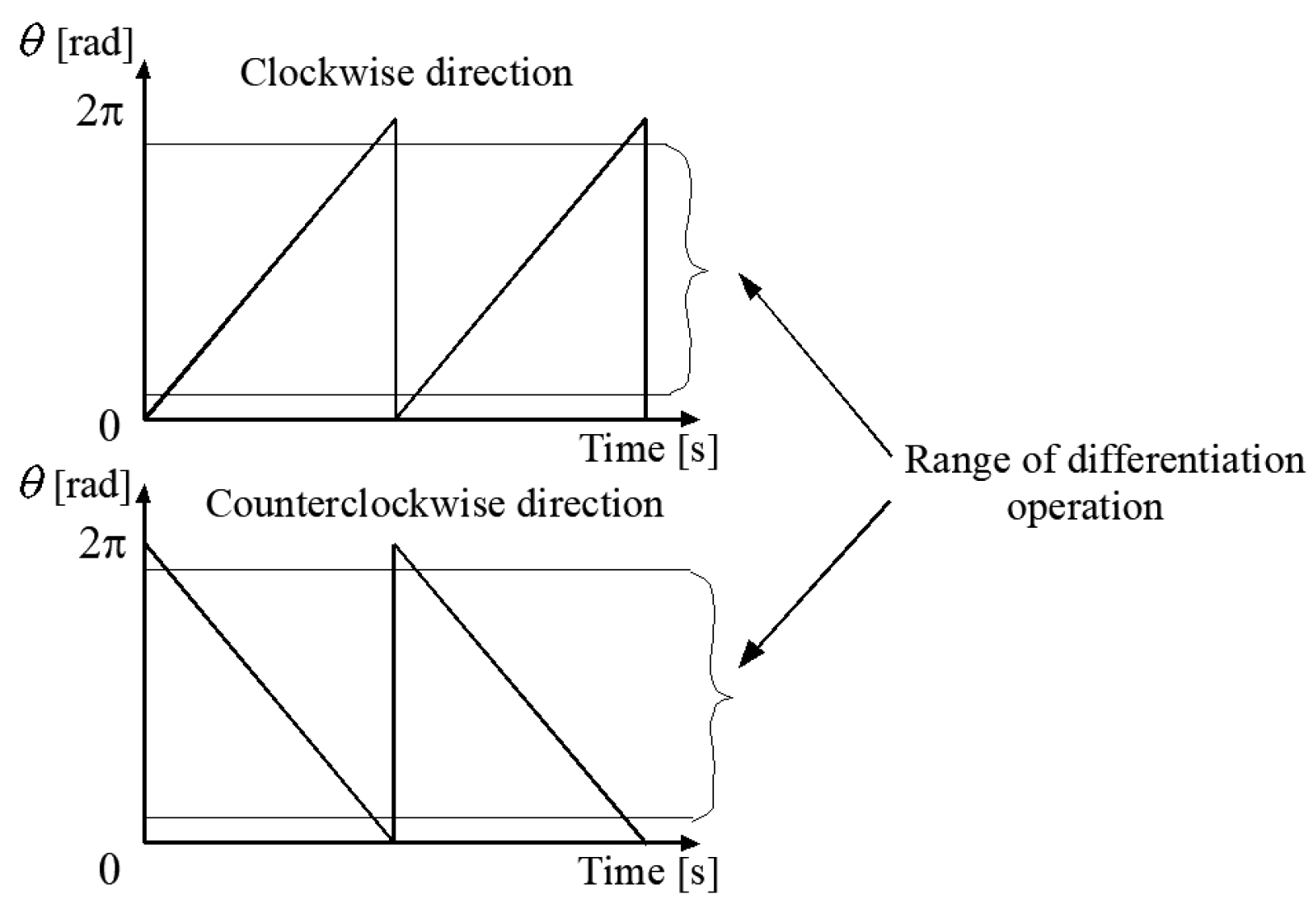
Due to the necessity to use a low-pass filter for the speed calculated from (36), there may be a partial loss of information regarding the speed value. If sensorless methods are used, which require the current angle to be determined using a filtered, estimated value of rotational speed, the calculated value of the rotor flux angle shall be corrected. The correction in the form of an empirically selected correction coefficients added to the calculated angle in the presented solution was applied. The value of the correction coefficient depends on the speed and parameters of the machine. The entire speed range can be divided into several sectors, for which these correctors should be selected experimentally. Due to used method of determining the angle of the rotor flux vector θr, which should be limited to the range of the angle from 0 to 2π, it is necessary to switch the values of this angle at the boundaries of the interval of variation. Differentiation of such a changing function of the angle θr for the determination of the synchronous flux speed at the sampling boundaries can result in the negative, false value of velocity. To eliminate such problem differentiation operation is performed in a narrowed range of angle changes which means that if the value of the rotor flux angle changes above or below the limitation, the actual current calculated value of the ωs is maintained. Since angle differential operation is performed within a limited angle range, this means that for a short period of time outside the limitation range the rotational speed value is not actual. However, this issue is not of great importance since the dynamics of the studied electrical part of the whole system is much faster than mechanical processes, so this property does not have any significant impact on the performance.
Figure 3.
Waveform depicting position angle of the rotor flux vector for 2 directions of shaft rotation.
Figure 3.
Waveform depicting position angle of the rotor flux vector for 2 directions of shaft rotation.
The differential operation used introduces sone errors to the value of the estimated angular speed, so the filtering operation is used and becomes necessary to avoid the real-time running DSP program entering an algebraic loop. In such a system, the value of the variable is calculated, which is also needed at the very time to determine it. This can be remedied by adding, for example, a delaying element in the calculation path containing a feedback loop [18].
Figure 4.
Numerical interference resulting from differentiation operations (a) without LPF, (b) with low-pass filter.
Figure 4.
Numerical interference resulting from differentiation operations (a) without LPF, (b) with low-pass filter.
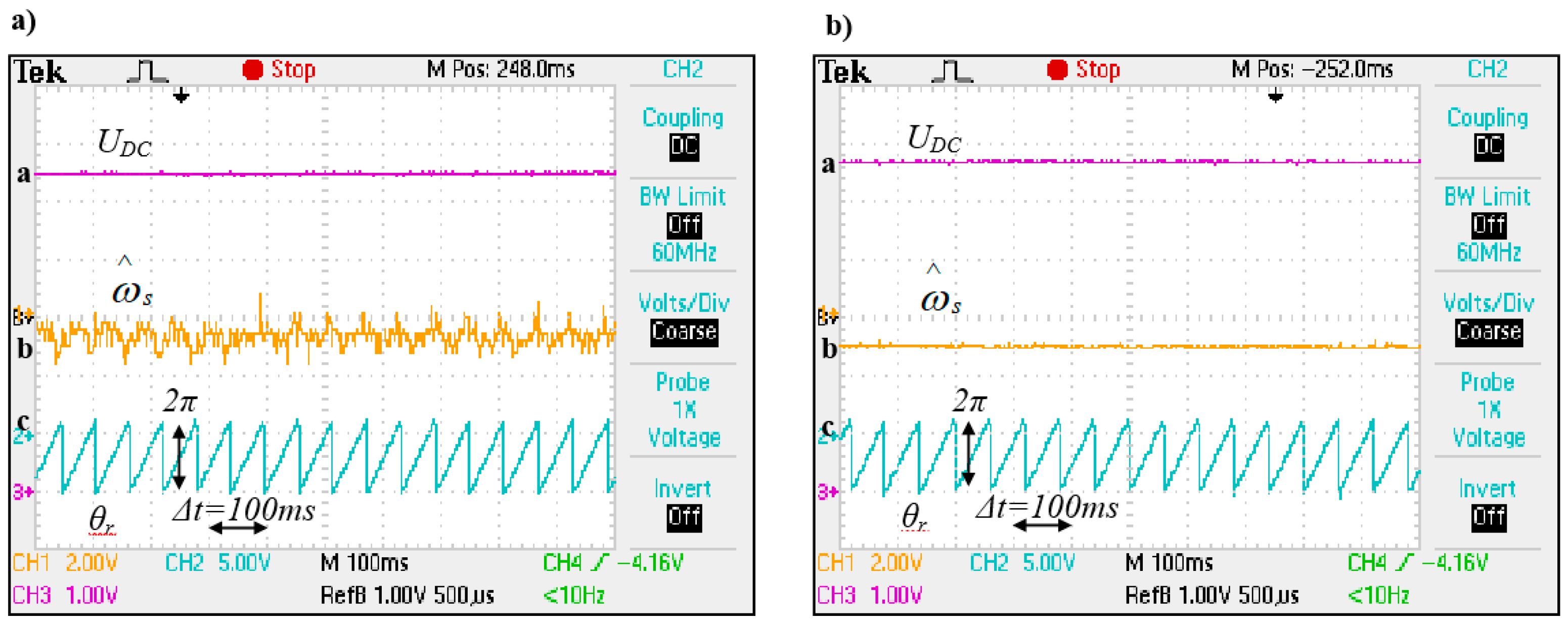
In the presented estimation method, the rotational speed and the angle of the rotor flux vector are determined from the values of voltages and currents, which are determined in the next calculation cycle of the control program using these variables. In this way, an algebraic loop would be created if the additional inertia resulting from the filtering operation was not introduced.
To filter the estimated speed signal, a 1st order low-pass filter was used, given by the (37) and then discretized into a DSP code:
Where is a filter time constant, fc denotes filter cutoff frequency.
The cutoff frequency value has been selected empirically, so that filtering operation was effective while maintaining good dynamics of the system.
5. Starting and Initial Excitation of a Rotating Generator in a Sensorless System
An important issue of generator startup operation in a sensorless system is to determine the correct frequency of the inverter aligned with the rotational speed of the shaft. This problem does not occur in drive systems because the angular velocity of the motor shaft is imposed by the frequency of the voltage generated by the inverter powering the stator windings. The matching of the inverter frequency and the angular velocity of the rotor occurs during the motor start-up process, noting that the inverter starts with zero initial conditions, i.e. from zero frequency and the rotor from zero speed, respectively. A discrepancy between the angular velocity of the rotor and the frequency of the inverter can only occur in emergency conditions, e.g. after a temporary loss of voltage supplying the motor. In this case, some converter manufacturers for drives with an induction motor use the so-called interception procedure, i.e. re-synchronization of the angular velocity of the rotor and the frequency of the inverter [19].
The analysis of the problem shows that due to the assumed lack of charging of the capacitor during the start-up of the asynchronous generator, it is necessary to limit the value of the inverter output voltages during the frequency search procedure so that the currents flowing through the windings are not too excessive. The method consists, similarly to the algorithms of "capturing" the rotation of motor shaft, in a rapid change in the frequency of the inverter, with the actual modification concerning the direction of changes in the frequency of the inverter (see Figure 5). In the considered issue, it is more advantageous to change the voltage frequency of the machine inverter from the minimum frequency to the maximum value provided for in the control algorithm. The advantage of such a solution is that the system works at a frequency lower than the frequency resulting from the rotational speed, i.e. in the generator mode during the search for rotational speed. In this case, there will be no situation in which the generator goes into a motoring mode.
Another advantage of this method is when the inverter frequency approaches the desired value of rotational speed, the generator, despite the greatly reduced voltage, is able to visibly recharge the capacitor of the intermediate circuit.
In the intermediate DC bus waveform, when the frequency of the output voltage of the inverter is aligned with the frequency of shaft rotation, the phenomenon of charging the electrolytic capacitor occurs. At this moment, the system, operating at a reduced voltage, has a slip suitable for producing such a value on the SEM terminals that the machine starts to generate current. In the proposed system, this property of the machine is used as one of the elements for determining the rotational speed of the rotating machine. The information about the frequency of the angular speed, coming only from the measurement of voltage on DC rails, is insufficient to accurately determine the quantity due to the lack of the slip value at a given moment and the possible disturbances in the voltage measurement. The algorithm for determining the angular velocity of the rotor works in such a way that the values of currents in the d-q system are constantly calculated using the angle of the flux vector, determined by integrating the frequency. Due to the small amplitude of the voltage and the differences in the frequency of rotation of the shaft and the frequency of the inverter, the waveforms of the currents calculated in this way are not decoupled quantities. When the frequency value of the inverter approaches the rotation frequency of the machine shaft, the active current gets close to zero while on the other hand, the reactive current takes positive values.
Since the active current has a negative value over a wide frequency range at the start-up procedure, this means that the examination of only the sign change of the current also does not clearly determine the exact moment when the rotational speed of the machine equals the frequency of the inverter. To determine the speed precisely, a voltage sign change condition should be introduced. Since the DC voltage value on the capacitor of the intermediate circuit is measured in the generating mode of operation, it is possible to check the moment and the corresponding speed at which the power sign, i.e. the sign of the DC voltage derivative on the capacitor, changes. In case the frequency of the inverter approaches from below to the rotational frequency of the machine, the DC voltage increases, reaches its maximum when the slippage has a maximum value and decreases when the frequency of the inverter generated voltage exceeds the value of the rotational frequency of the machine. Such information is sufficient to determine the rotational speed of the generator.
Table 1 summarizes the numerical simulation results of the error in determining the angular velocity of the rotor using the presented method at a fixed initial voltage depending on the rotational speed.
The error value decreases with the speed, which is related to the higher torque of the machine generating higher currents at a high shaft speed and, as a result, a DC increased voltage when the frequency of the rotor and the power supply of the machine are equal.
After determining the initial value of the rotational speed, the obtained value is given into the generator control algorithm. Since the sensorless control methods used with a voltage-current model and a machine state observer are based on the values used for control, it is impossible to start the control system without the initial conditions. The initial velocity value determined in the manner described above in a sensorless system does not carry additional information regarding the determined initial values of currents and voltages, which makes it necessary to pre-control the generator by another method - which does not require initial conditions. After determination of the rotor velocity value the calculations are carried out using an algorithm based on the machine current model.
6. Selected Simulation Tests of Cage Generator Excitation in the Sensorless Mode
Before setting up and programming the experimental stand, several simulation tests were carried out to verify the correctness of the theoretical assumptions as well as the original algorithms used. During the digital simulations, the operation of the cage generator system was checked at constant and variable speeds and under load. For this part of the simulation research, the model of the machine discussed in Subsection 3 was used, together with the model of the converter, which was created based on [20]. The waveforms presented in Figure 6 were performed for the starting settings of the UDC voltage regulator, hence the relatively high error value (approx. 6-7V) in the steady state. For this reason, the times to reach values close to the set values are also shorter. The optimal parameters of the controllers were set after the start-up time and for a system operating with a load, the active current limitation was set to the rated value.
SCIG start up and excitation simulation tests for a sensorless controlled system were performed for the same angular velocities as presented in Figure 6.
The beginning of the angular speed-seeking algorithm is marked in Figure 6a and Figure 6b as START. Figure 6a shows the current waveforms isd and isq when the generator is switched from current mode into the sensorless mode of operation.
As is presented there is an overshoot of the stator voltages usd and usq related mainly to the difference in real rotational speed, estimated in the current model mode and in the current-voltage model. The differences between these values affect the determination of the angle of the rotor flux vector, which results in the calculation of different values of currents and on this basis the setting of the converter voltages. The selection of the minimum operating time in current mode depends primarily on the settings of the isd and isq current regulators and actual DC bus voltage. Dynamic-improving settings result in faster setpoints being obtained at the expense of faster discharge of the intermediate circuit capacitor. The results of simulation studies show that it is possible to excite a machine without external sources charging the capacitor during the process of tracking the rotational speed and excitation in both sensorless control systems.
7. Experimental Test Stand and Chosen Results
The parameters of the replacement circuit of the induction machine are important for the creation of control programs and the implementation of complex control methods. Some parameters are not specified by manufacturers, so they should be determined using methods used to identify machine parameters [21].
Using the no-load (idle run) test, the excitation current and mechanical losses (bearing torque, ventilation losses) can be determined. The test consists of supplying a voltage of the rated amplitude and frequency of the motor stator windings at idle. Part of the power is transferred to losses in the core and windings. In such a system, the machine operates at a rotational speed not much lower than the synchronous speed, which gives approximately zero slippage value. A substitute scheme for such a sample is shown in Figure 7.

Table 2.
Results obtained in the no-load induction machine test.
| Uf0 - phase voltage | 230 V |
| If0 - phase current | 2.1 A |
| If0max - Idle current amplitude | 3.0 A |
| fs – supply voltage frequency | 50 Hz |
| Pf0 - idle run power drawn | 100 W |
The values measured in the idle test are the rms values of the phase currents and supply voltage of the stator winding. From this data, the total power delivered to the machine at idle was calculated.
Assuming that Rc is much larger than Rs and Xlr, it is possible to determine Rc and Lm from the substitute diagram.
The test with the locked motor shaft, similarly to the test of short-circuiting the transformer, allows obtain information about the dissipation impedances and rotor resistance.
During the second test, the rotor was blocked and the machine was supplied with a voltage lowered by the autotransformer at such a value as to induce a rated current flow in the stator windings. The phase voltage and power of one phase were measured.
The determined parameters of SCIG generator were used to create their computer models utilized in numerical simulation studies and then to arrange the control programs of the experimental system.
Based on the previously presented theoretical considerations and simulation studies of the cage generator system, the voltage value on the capacitor of the UDC intermediate circuit at the time of switching on the system depends to a large extent on the parameters of the machine. To verify the correctness of the adopted model, a series of experimental studies of the real system were carried out.
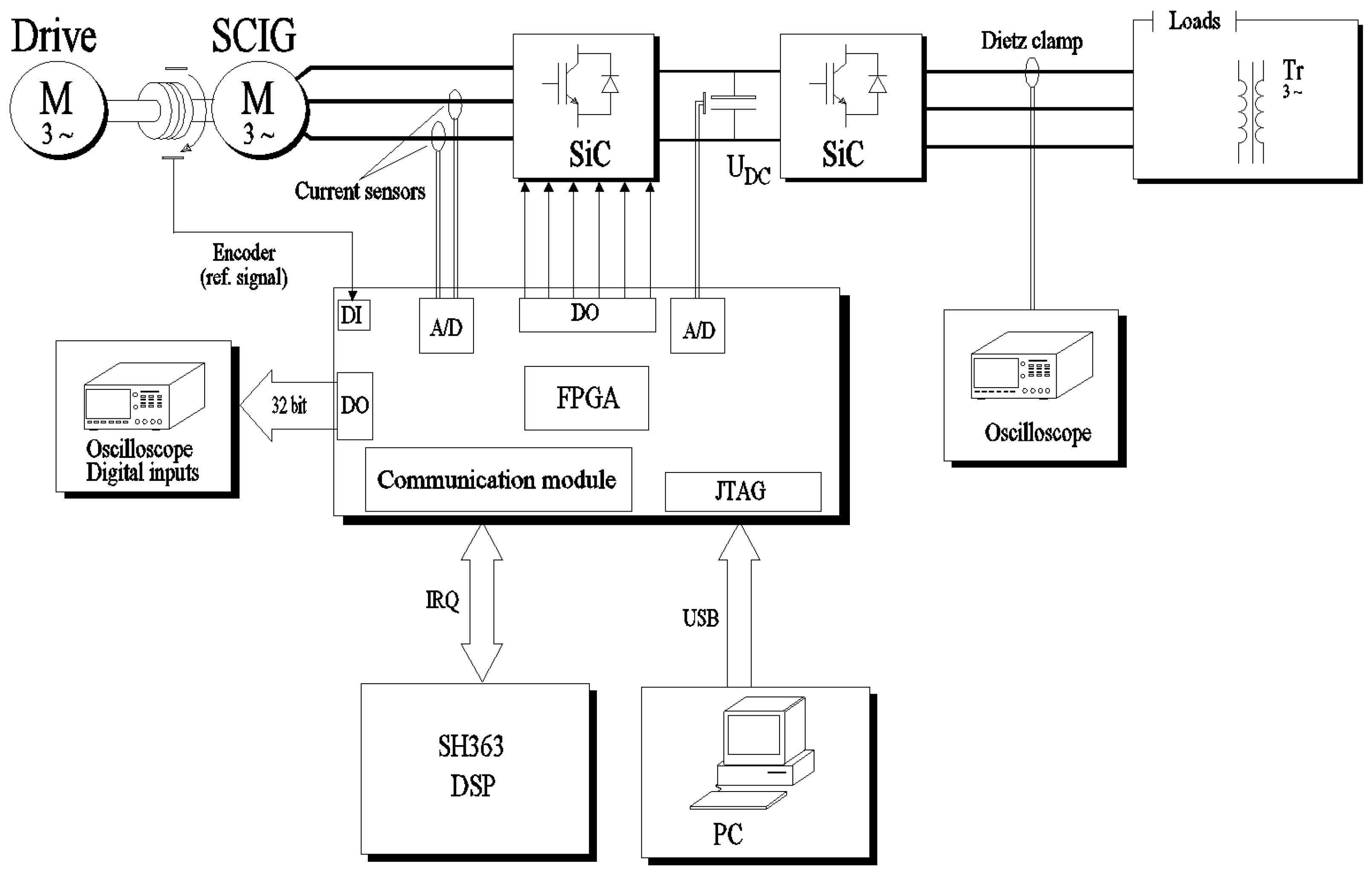
Figure 8.
Diagram of the experimental rig.
On the basis of the results of simulation tests, a program for the experimental system was created, aimed at checking the correctness of the method of searching for the rotational speed of a rotating generator proposed in the dissertation. According to the assumptions adopted during the simulation tests, the capacitor of the intermediate circuit was charged to a voltage of 300 V, then the power source was disconnected, and the initial speed search procedure was started. The small amplitude current generated by the converter caused the capacitor to discharge, and the additional voltage loss of the capacitor resulted from the flow of current through the discharge resistors which can be observed in waveforms in Figure 9. In a practical (industrial) application, the possibility of increasing the value of these resistors during start-up should of course be considered to reduce or eliminate loss currents. In the paper, the results with permanently attached resistors discharging voltage on the inverter are presented.
The correctness of the algorithm was proven by a series of experimental studies, which consisted in supplying the machine windings with a set, non-zero usd voltage with a value reduced from the nominal value, for several speeds selected from the assumed range. Selected results of experimental studies of the applied algorithm for tracking initial angular speed of a generator are presented in Figure 9.
Analyzing the above figures, the higher the rotational speed of the shaft, the greater the voltage drop on the capacitor of the intermediate circuit. This is clear because it takes longer time for the "test" pulsation to capture the higher rotor speed, during which the testing pulsation reaches a value close to the rotational speed of the shaft. The question arises whether in such an unfavorable case, when the voltage level of the intermediate circuit is low, the generator will be able to excite. As shown by the results of simulation tests, the excitation phenomena should proceed correctly at the assumed voltage range at the assumed speeds. For this purpose, the algorithm for tracking the speed values has been supplemented with the procedure for starting and excitation of the sensorless-controlled cage generator described previously. Figure 10 shows experimental waveforms illustrating the process of detecting generator speed and excitation for different rotational speeds. As can be seen when the control algorithm is switched from current to sensorless mode of operation, the value of the active current increases significantly when the capacitor is charged to the set value of the voltage and then stabilizes to a value close to zero. This increase is caused by the rapid change of the current limitation to the maximum value of the active current in the sensorless current-voltage control which can be mitigated by introducing speed dependent PI controller coefficients.
The results shown prove that after switching to sensorless mode, the system works stably, the estimated speed is consistent with the set, the voltage on the capacitor reaches the set value. As further experimental trials have shown, the proposed velocity and excitation search system is equally effective for sensorless control using the machine state observer. The experimental results obtained during the research of the process of starting a cage generator in a sensorless system are highly consistent with the results obtained with numerical simulations which conclude that the method developed by the author is substantively and physically correct.
In addition to the presented results, several additional experimental studies were carried out in terms of the quality of capacitor voltage control in the intermediate circuit of the cage generator operating in an island mode in accordance with the adopted assumptions regarding sensorless control. The tests included testing the voltage stabilization of the intermediate circuit after start up and idle run at different speeds of the generator in the range from 40 to 100 percent of the rated speed, as well as testing the stabilization of the voltage of the intermediate circuit under a load at variable speed values. It was assumed that in all experimental measurements the settings of the regulators are the same. The tested machine was previously started and loaded to stabilize the rotor temperature so that the change in the rotor time constant had as little impact as possible on the results obtained.
8. Conclusions
The paper presents the theoretical concept and results of simulation and experimental research of asynchronous cage generator startup and excitation process without use of rotational speed sensor. During the research, special attention was paid to the implementation of generator control methods in systems without a speed sensor, as well as the excitation conditions of generators powered by a transistor-based machine side inverter. For the purposes of the research, original simulation software written in C++ was prepared and later programs for the experimental system were written based on the numerical simulation results. Because the DSP software uses the C++ programming language, all tested control algorithms along with software regulators have been carried over entirely from the simulation software. This allowed authors to focus on problems related to hardware implementation, and on minimizing interferences occurring in experimental systems. The results obtained in excitation and steady-state operation prove that sensorless methods of control of the cage generator show the same operating properties as systems with encoders and even exceed them in the presence of high disturbances. During the excitation and start-up of the generator operating in sensorless systems, a current model was implemented to determine the initial conditions for machine models used in sensorless control. As the research conducted has shown, this solution is so universal that it can be used with virtually any method of sensorless control, while achieving high efficiency. During the work, the initial velocity detection procedure known from the drive systems was modified and implemented to the specifics of generator operation.
Author Contributions
Conceptualization, Maciej Kozak..; methodology, Maciej Kozak.; software, Marcin Kozak and Kacper Olszański.; validation, Marcin Kozak and Kacper Olszański.; formal analysis, Marcin Kozak and Kacper Olszański.; investigation, Maciej Kozak.; Kacper Olszański and Marcin Kozak; resources, Kacper Olszański.; data curation, Marcin Kozak.; writing—original draft preparation, Maciej Kozak.; writing—review and editing, Marcin Kozak and Kacper Olszański.; visualization, Maciej Kozak.; Kacper Olszański and Marcin Kozak.; supervision, Maciej Kozak.; project administration, Maciej Kozak; funding acquisition, Maciej Kozak. All authors have read and agreed to the published version of the manuscript.
Funding
This research was funded by Polish Ministry of Science and Higher Education, grant number 2/S/KEiE/25.
Data Availability Statement
Data is unavailable due to privacy.
Acknowledgments The authors have reviewed and edited the output and take full responsibility for the content of this publication.”
Conflicts of Interest The authors declare no conflicts of interest The funders had no role in the design of the study; in the collection, analyses, or interpretation of data; in the writing of the manuscript; or in the decision to publish the results.
Abbreviations
The following abbreviations are used in this manuscript:
| SCIG | Squirrel cage induction generator |
| DSP | Digital signal processor |
| LPF | Low pass filter |
| DC, AC | Direct current, alternating current |
References
- Xu, L.; Guerrero, J.M.; Lashab, A.; Wei, B.; Bazmohammadi, N.; Vasquez, J.; Abusorrah, A.M. A review of DC ship-board microgrids—Part I: Power architectures, energy storage and power converters. IEEE Trans. Power Electron. 2022, 37, 5155–5172. [Google Scholar] [CrossRef]
- Aboelezz, A.M.; Sedhom, B.E.; El-Saadawi, M.M.; Eladl, A.A.; Siano, P. State-of-the-art review on shipboard microgrids: Architecture, control, management, protection, and future perspectives. Smart Cities 2023, 6, 1435–1484. [Google Scholar] [CrossRef]
- Kim, K.; Park, K.; Roh, G.; Chun, K. DC-grid system for ships: A study of benefits and technical considerations. J. Int. Marit. Saf. Environ. Aff. Shipp. 2018, 2, 1–12. [Google Scholar] [CrossRef]
- Satpathi, K.; Balijepalli, V.S.K.M.; Ukil, A. Modeling and real-time scheduling of DC platform supply vessel for fuel efficient operation. IEEE Trans. Transp. Electrif. 2017, 3, 762–778. [Google Scholar] [CrossRef]
- Luna, M.; La Tona, G.; Accetta, A.; Pucci, M.; Pietra, A.; Di Piazza, M.C. Optimal management of battery and fuel cell-based decentralized generation in DC shipboard microgrids. Energies 2023, 16, 1682. [Google Scholar] [CrossRef]
- Di Piazza, M.C.; Luna, M.; La Tona, G.; Accetta, A.; Pucci, M.; Pietra, A. A mixed AC/DC low voltage electrical distribution architecture for increasing the payload on ships. In Technology and Science for the Ships of the Future: Proceedings of NAV 2018: 19th International Conference on Ship & Maritime Research; IOS Press: Amsterdam, The Netherlands, 2018; pp. 230–237. [Google Scholar] [CrossRef]
- Zahedi, B.; Norum, L.E. Optimized efficiency of all-electric ships by DC hybrid power systems. Electr. Power Syst. Res. 2014, 112, 83–92. [Google Scholar] [CrossRef]
- Naugher, L.A. The Squirrel Cage Induction Machine as an Alternative to the Permanent Magnet Generator for Direct Drive Tidal Turbines. Ph.D. Thesis, Newcastle University, Newcastle upon Tyne, UK, 2018. [Google Scholar]
- Martínez-Rodrigo, F.; Ruíz-González, J.M.; Domínguez-Vázquez, J.A.; Herrero-de-Lucas, L.C. Sensorless control of a squirrel cage induction generator to track the peak power in a wind turbine. In Proceedings of the 28th Annual Conference of the IEEE Industrial Electronics Society (IECON 2002), Sevilla, Spain, 5–8 November 2002; pp. 169–174. [Google Scholar]
- Bašić, M.; Bubalo, M.; Vukadinović, D.; Grgić, I. Sensorless maximum power control of a stand-alone squirrel-cage induction generator driven by a variable-speed wind turbine. J. Electr. Eng. Technol. 2021, 16, 333–347. [Google Scholar] [CrossRef]
- Cárdenas, R.; Peña, R. Sensorless vector control of induction machines for variable-speed wind energy applications. IEEE Trans. Energy Convers. 2004, 19, 196–205. [Google Scholar] [CrossRef]
- Kubatko, M.; Bielesz, D.; Kirschner, S.; Hamani, K.; Kuchar, M.; Mrovec, T.; Prazenica, M. Sensorless direct field-oriented control of induction motor drive using artificial neural network-based reactive power MRAS. Sensors 2025, 25, 7135. [Google Scholar] [CrossRef] [PubMed]
- Kjellson, G. Sensitivity Analysis of Flux Estimation Methods for Field-Oriented Control of Induction Machines. Master’s Thesis, KTH Royal Institute of Technology, Stockholm, Sweden, 2024. [Google Scholar]
- Kozak, M.; Bronsky, R.; Matuszak, M. Application of squirrel cage generator control system utilizing direct torque control method as the shaft generator in a seagoing ship. Energies 2024, 17, 5985. [Google Scholar] [CrossRef]
- Kaczmarek, T.; Zawirski, K. Układy napędowe z silnikiem synchronicznym; Wydawnictwo Politechniki Poznańskiej: Poznań, Poland, 2000. (In Library) [Google Scholar]
- Boldea, I.; Nasar, S.A. Vector Control of AC Drives; CRC Press: Boca Raton, FL, USA, 2000; (Internet Archive). [Google Scholar]
- Luenberger, D.G. Observing the state of a linear system. IEEE Trans. Mil. Electron. 1964, MIL-8, 74–80. [Google Scholar] [CrossRef]
- Griffiths, D.V.; Smith, I.M. Numerical Methods for Engineers: A Programming Approach; Blackwell Scientific Publications: Oxford, UK, 1991; (Internet Archive). [Google Scholar]
- LS Industrial Systems. SV-iP5A User Manual; LS Industrial Systems, 2009; (ManualsLib). [Google Scholar]
- Mohan, N. Advanced Electric Drives: Analysis, Control and Modeling Using Simulink; MNPERE: Minneapolis, MN, USA, 2001; (AbeBooks). [Google Scholar]
- Jurkovic, S. Induction motor parameters extraction. Michigan State University, College of Engineering, 2000. Available online: http://www.egr.msu.edu/~jurkovi4/motor-parameters.pdf (accessed on 8 December 2025). (Massachusetts Institute of Technology).
Figure 1.
Machine state observer structure.
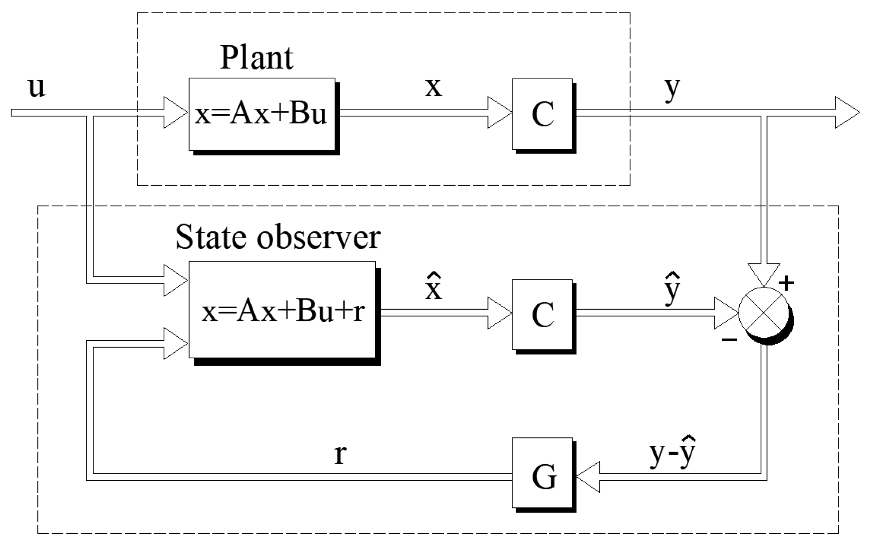
Figure 2.
Sensorless control with machine state observer module.
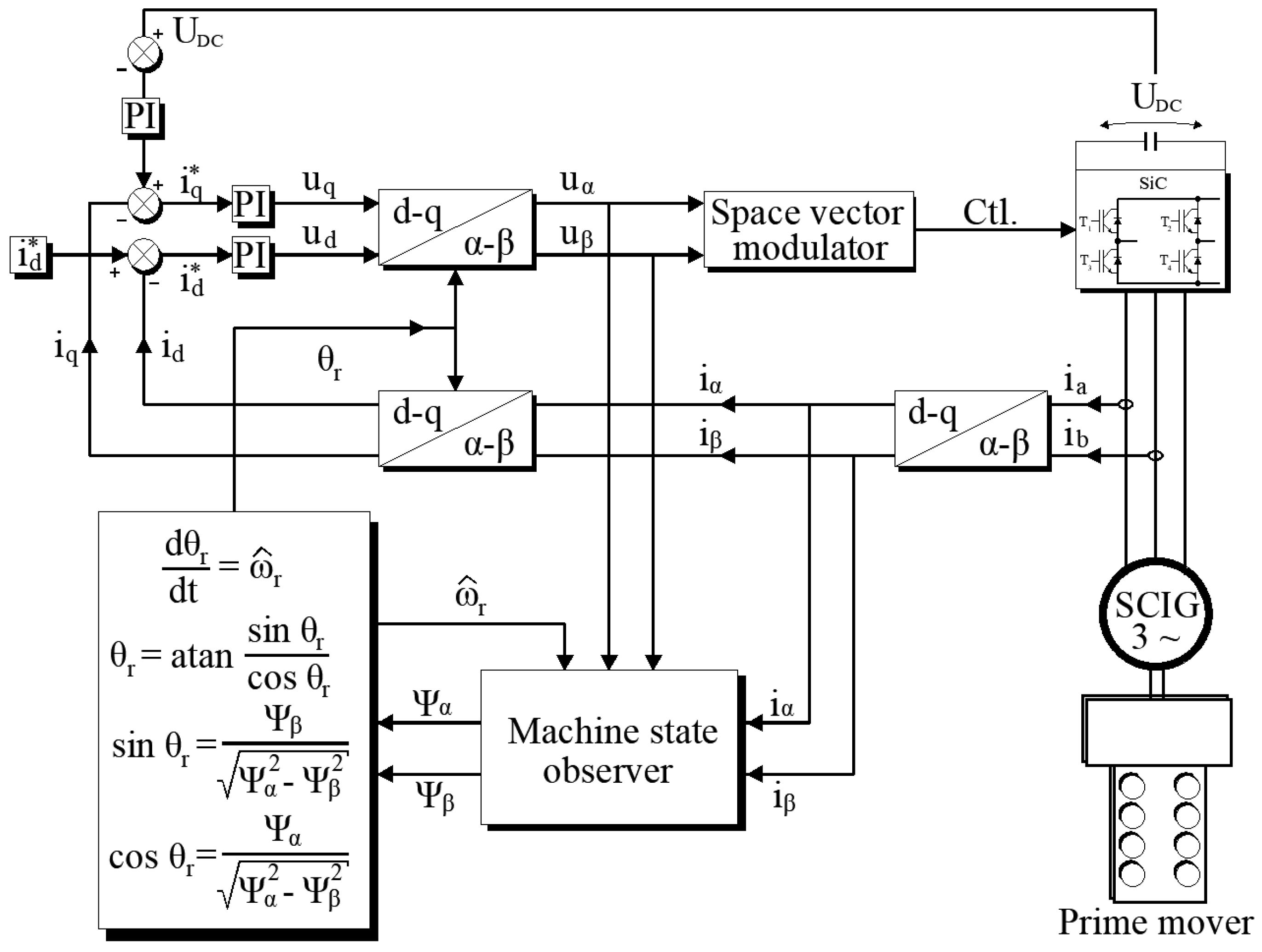
Figure 5.
Example waveforms of the results of the inverter frequency detection simulation for the initial voltage in the intermediate circuit of 300V and at a rotational speed of 126 rad/s.
Figure 5.
Example waveforms of the results of the inverter frequency detection simulation for the initial voltage in the intermediate circuit of 300V and at a rotational speed of 126 rad/s.
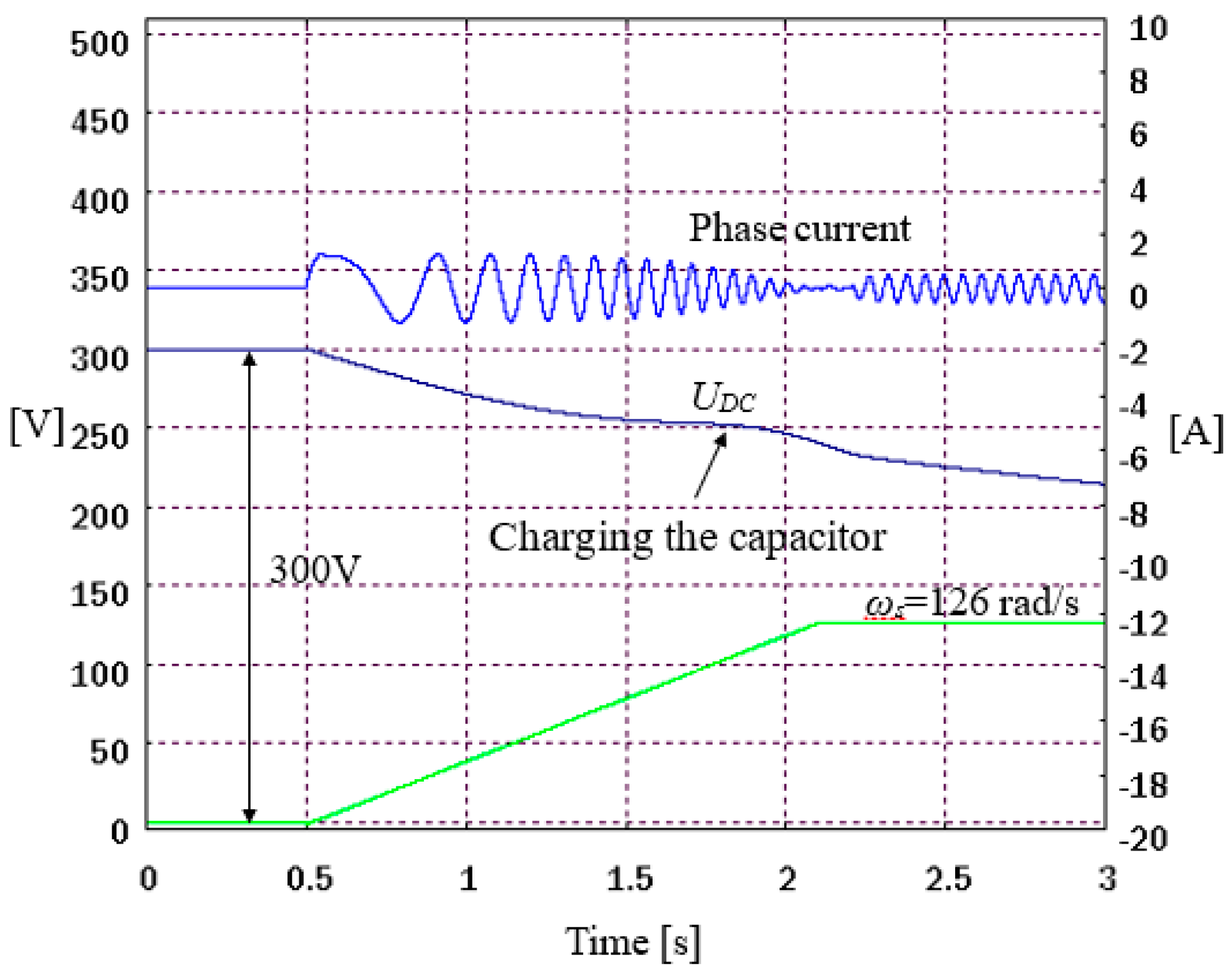
Figure 6.
Tracking the initial rotational speed and excitation of the SCIG in a sensorless control system with a current-voltage model for selected rotational speeds. Rotational speeds: (a) 126 rad/s, (b) 189 rad/s.
Figure 6.
Tracking the initial rotational speed and excitation of the SCIG in a sensorless control system with a current-voltage model for selected rotational speeds. Rotational speeds: (a) 126 rad/s, (b) 189 rad/s.
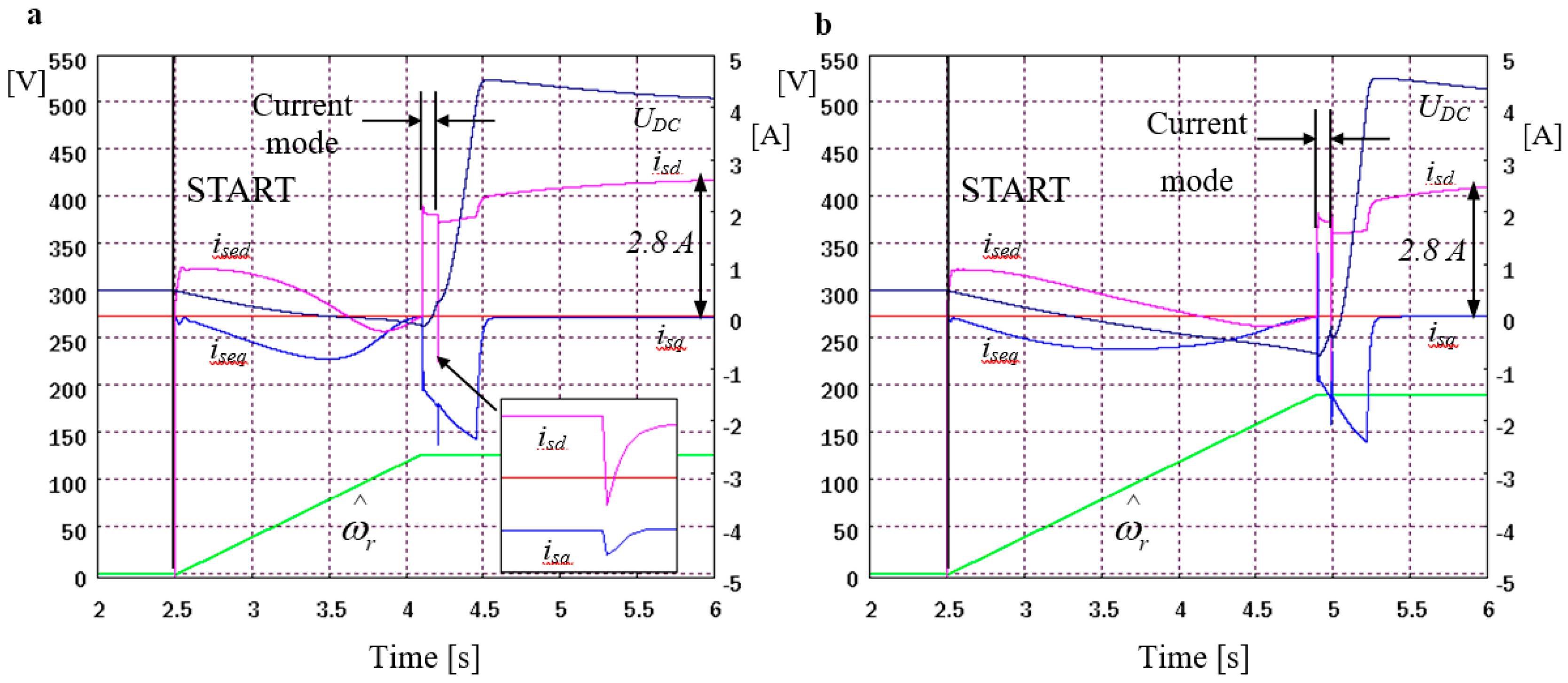
Figure 7.
Idle test SCIG circuit.
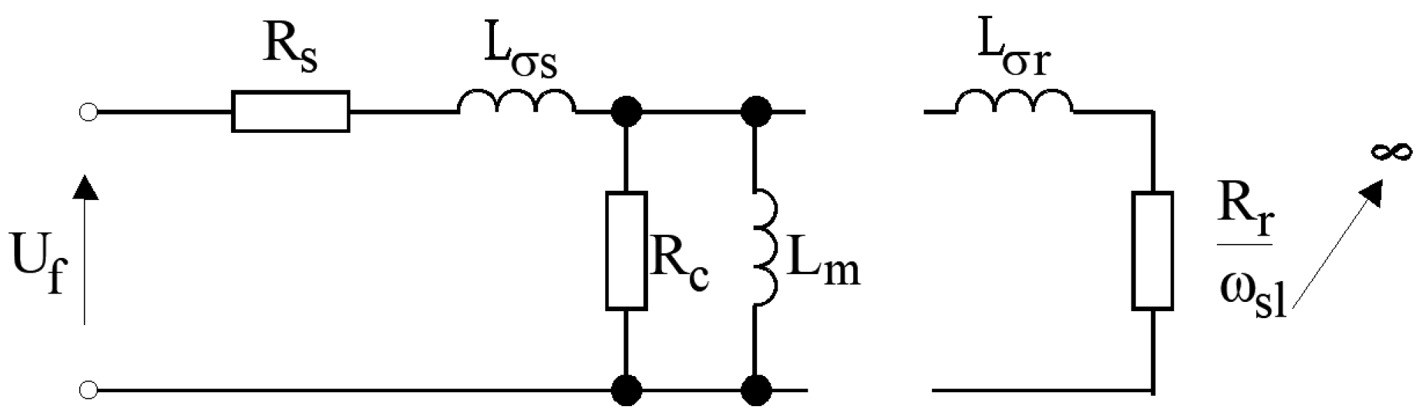
Figure 9.
Experimentally determined results of the tracking for the angular speed of a cage generator. Rotational speeds: (a) 126 rad/s, (b) 189 rad/s.
Figure 9.
Experimentally determined results of the tracking for the angular speed of a cage generator. Rotational speeds: (a) 126 rad/s, (b) 189 rad/s.
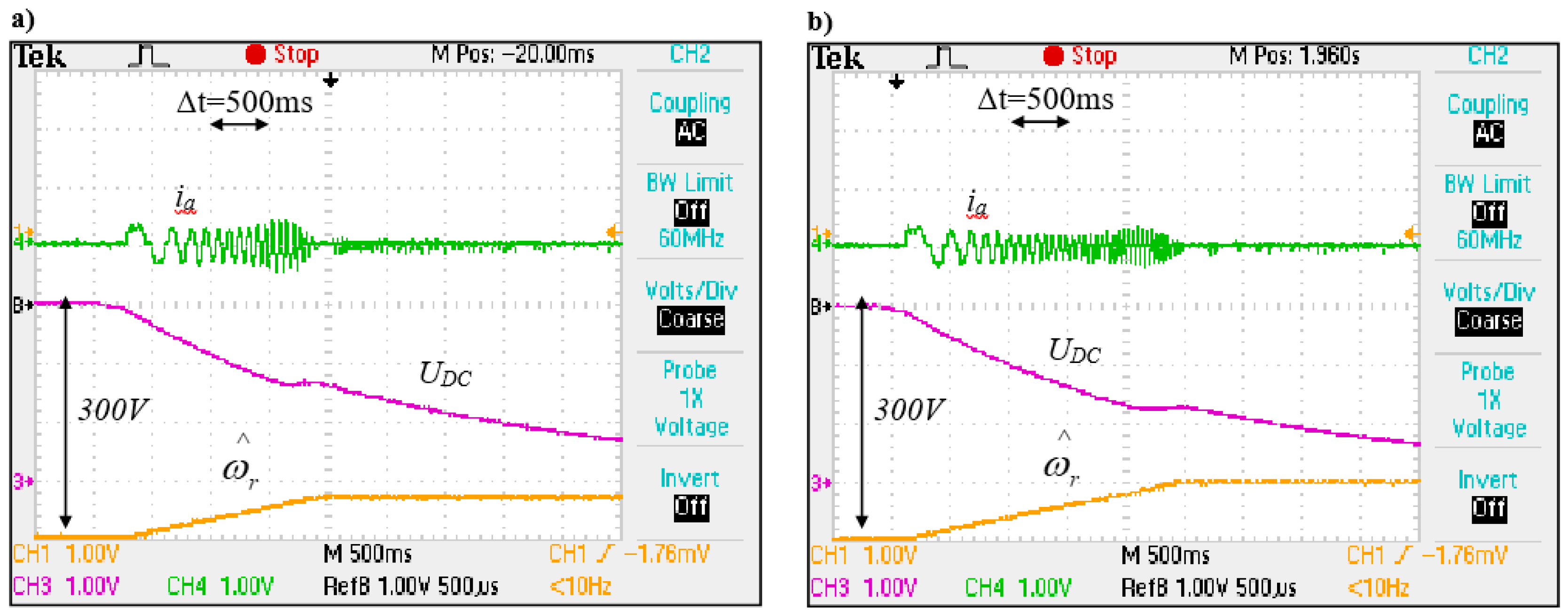
Figure 10.
Experimental results of angular speed tracking and an excitation process of a cage generator. Rotational speeds: (a) 126 rad/s, (b) 189 rad/s.
Figure 10.
Experimental results of angular speed tracking and an excitation process of a cage generator. Rotational speeds: (a) 126 rad/s, (b) 189 rad/s.
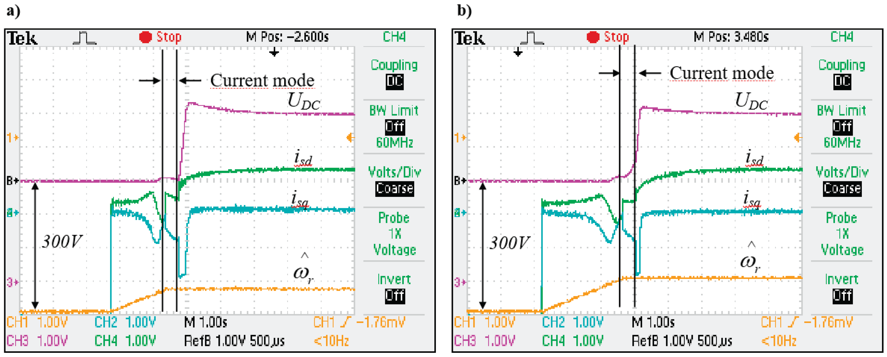
Table 1.
Results of simulation studies for the determination of angular speed error.
| ωr [rad/s] | 126 | 189 | 251 | 314 |
| [rad/s] | 128.39 | 191.24 | 253.18 | 316.14 |
| Δωr [%] | 1.89 | 1.18 | 0.86 | 0.68 |
Disclaimer/Publisher’s Note: The statements, opinions and data contained in all publications are solely those of the individual author(s) and contributor(s) and not of MDPI and/or the editor(s). MDPI and/or the editor(s) disclaim responsibility for any injury to people or property resulting from any ideas, methods, instructions or products referred to in the content. |
© 2025 by the authors. Licensee MDPI, Basel, Switzerland. This article is an open access article distributed under the terms and conditions of the Creative Commons Attribution (CC BY) license (http://creativecommons.org/licenses/by/4.0/).
Copyright: This open access article is published under a Creative Commons CC BY 4.0 license, which permit the free download, distribution, and reuse, provided that the author and preprint are cited in any reuse.


