Submitted:
05 December 2025
Posted:
05 December 2025
You are already at the latest version
Abstract
The moiré effect is a physical phenomenon in periodic (or nearly periodic) structures. A straightforward approach does not enable us to fully understand this complex phenomenon and describe it in all its details. Therefore, modeling of the effect is often necessary. The combined simulation incorporates both physical and computer simulations. Computer tools for simulating the moiré effect in parallel layers and volumetric displays are presented, along with methods for replacing original microscopic objects with their macroscopic equivalents, thereby facilitating the development of a physical model. (It resembles an aerodynamic model of an aircraft or vehicle.) The combined simulation was made for 3D displays, cylindrical structures (single- or double-layered nanoparticles), and volumetric 3D structures. The results can be applied to nanoparticles, crystallography, and the improvement of the visual quality of 3D displays.
Keywords:
combined simulation
; moiré simulation
; moiré effect
; 3D moiré
; volumetric display
; multilayer moiré
; cubic lattice moiré
1. Introduction
The moiré effect is an optical interaction (interference) between projections of layers observed in periodic structures (grids, lattices) viewed in transmission. Moiré fringes are alternating dark and light areas with a relatively low spatial frequency that is absent in the original structures [1,2,3,4].
Typically, the effect is considered in coplanar layers, i.e., in two dimensions. Sometimes, the moiré effect is investigated in three dimensions [5], e.g., in flat layers separated by a gap [6,7,8] and in three dimensions: in rectangular parallelepiped [4], wedge (triangular prism) [9], cylinder [10,11,12,13], and their combinations [14].
The macro-level moiré has been well investigated in visual displays [15,16,17,18,19,20,21]. The structure of multiview autostereoscopic displays typically comprises two parallel layers with a cell-size ratio close to an integer. The moiré effect negatively affects the quality of the visual image; therefore, this harmful (in displays) effect should be avoided or at least reduced (minimized), especially in autostereoscopic and volumetric 3D displays [22,23,24] Particularly, there are methods of removal based on geometry [25,26], image processing [27], based on neural networks [28,29,30] and special design [31,32]. From the opposite point of view (i.e., as a useful effect), the moiré effect is used for security [33,34] and measurements [35,36,37,38,39,40,41,42,43].
At the nano-scale, the moiré effect is widely investigated [44,45,46,47,48,49,50]; particularly, in single-walled [51,52,53,54] and double-walled nanotubes [55,56]. Also, the effect is investigated in 2D materials including twistronics [57,58,59,60,61,62,63,64,65,66,67,68,69] ands well as in three- and multilayuered graphene [70,71].
The moiré effect is complex phenomenon, affected by many factors. However, not all problems can be solved analytically. In many cases, modeling is required, which includes either computer simulation or a physical model. Apart from that, the simulation has a more general meaning: it shows a clear visual effect, making it understandable. Computer simulation, combined with experiments on a physical model, constitutes a comprehensive study. The combined simulation involves physical modeling and computer simulation.
In particular, the moiré effect is simulated in visual displays [6,8,26,72], including the color effect [73,74], as well as using special software [75,76]. Also, display elements (backlight, touchscreen) were modeled [77,78,79,80,81,82]. Simulation of projection moiré was also made (basically, for measurements) [83,84]. We also have to mention general-purpose and special simulators [85,86,87,88,89]. At the nano-level, the moiré effect is simulated in graphene and in other bilayers [90,91,92,93,94,95,96,97,98].
The current paper describes computer simulation and physical model using three examples: i) parallel planar layers (displays); ii) 3D shell objects (cylindrical nanoparticles, SWNT), spherical surface; iii) 3D volumetric multilayered objects (3D array such as an LED cube).
We assume that the radius of the visibility circle [1] is shorter than the distance from the origin of the spectral domain to the closest spectral component of either grid. In such a case, the grids themselves are unrecognizable (as higher spatial frequencies), whereas the moiré patterns (lower spatial frequencies) are clearly visible and can be visually separated. We only consider the period and orientation of the moiré patterns.
In Sec. 2, the computer simulation tool shows moiré patterns in planar, parallel layers. The tool is controlled interactively and operates in two modes: overview and detailed.
In Sec. 3, the moiré effect in objects with radial symmetry (hollow single-walled cylindrical and spherical objects) was investigated. The moiré effect in chiral nanoparticles has been modeled using macroscopic objects or planar grids, and the resulting patterns can be simulated using computer-generated images. The combined approach can be applied to MWNT.
In Sec. 4, the moiré effect in the essentially volumetric 3D case (a cube) is investigated. Visual corridors are moiré patterns. We carried out computer simulations and physical experiments; the distinctive angles of the moiré patterns are determined in three types of cubic lattices (simple, body-, and face-centered). These three cases (dual/multiple layers, cylinders, sphere/cube) confirm the usefulness of the combined simulation.
2. Materials and Methods
This section provides brief descriptions of three cases of combined simulation.
For planar displays, simulating each case individually was practically inconvenient, although the experimental values demonstrated a good agreement with the simulation (within 2–4%) [6,8]. Therefore, specialized computer simulation tools were developed to study the behavior of moiré waves in autostereoscopic displays. The simulation is based on spectral trajectories, the multiplicative model, the Fourier transform, the projection transform, and the concept of the visibility circle [1].
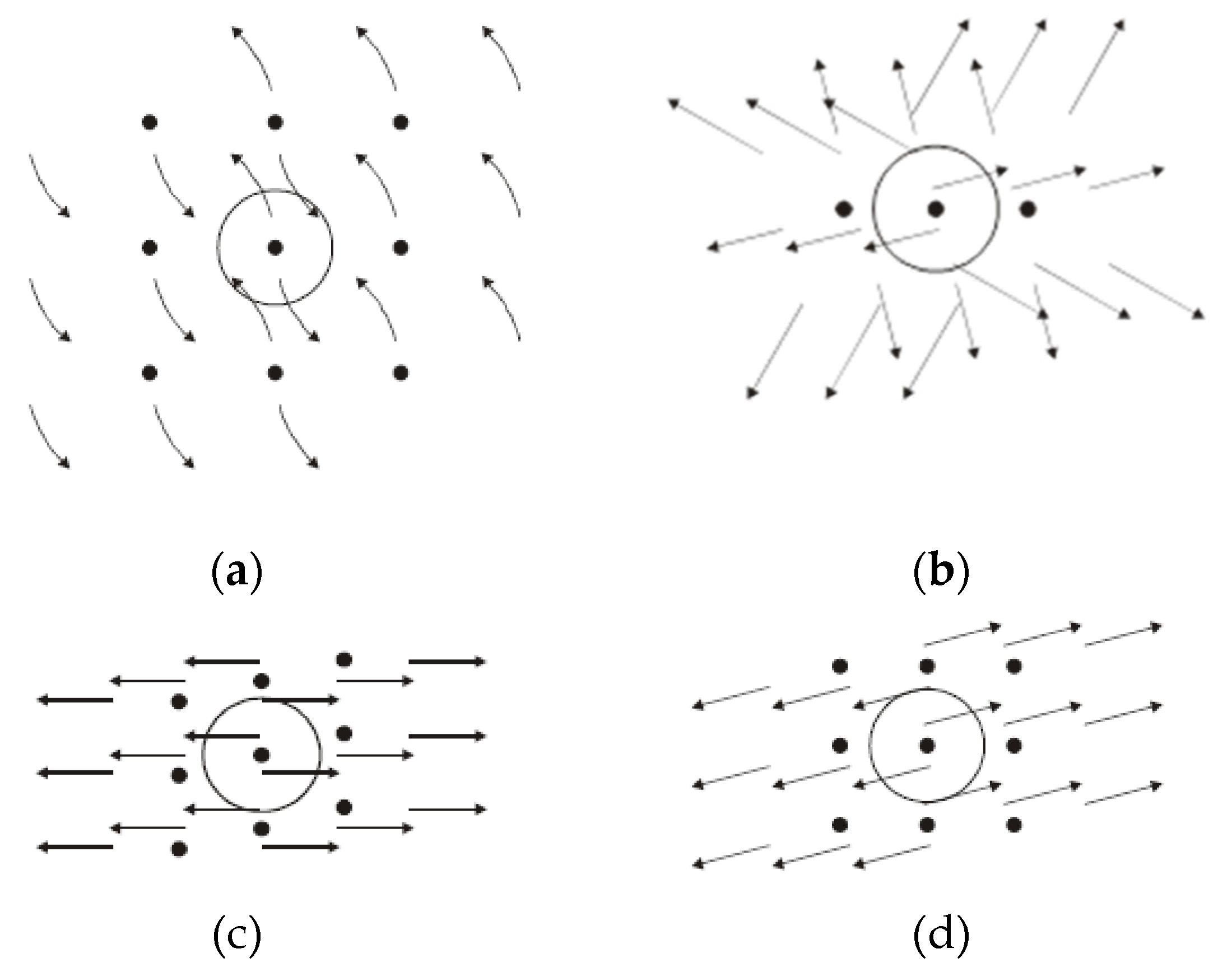
The positions of the spectral components in parallel layers are as follows,
Spectral trajectories [99,100] in layered displays appear when one parameter in Eq. (1) is not constant (like α, ρ, σ1, or σ2 in Eqs. (2)-(5) below)
where the values kn, αn, pn, qn are attributed to the n-th grid (n = 1, …, N) as follows: two former values are the basic wavenumber and the rotation angle, while pn is an integer number within the limits -qn and +qn, and t is a dimensionless parameter.
Figure 1.
Examples of spectral trajectories with one harmonic (sinusoidal case), obtained by simulation for different running parameters; in (a) .. (d), parameters are α, ρ, σ1, and σ3, respectively. Adapted from [100] with permission.
Figure 1.
Examples of spectral trajectories with one harmonic (sinusoidal case), obtained by simulation for different running parameters; in (a) .. (d), parameters are α, ρ, σ1, and σ3, respectively. Adapted from [100] with permission.
The developed tool shows the simulated moiré patterns in computer-generated black-and-white sinusoidal grids [8,99,101]. Source images from an external file can also be used. The tool (see Figure 2) enables semi-automatic measurements and visual tracking of spectral peaks. The outline mode displays the spectral trajectories (sketches or result of FFT); the detail mode shows the visual effect along with the numerical characteristics of the patterns, see Figure 2
Grid parameters are adjustable (the periods, the observer’s displacement by two coordinates, the distance to the screen, the gap, the slant angle, and the like). Direct calculations using the Fourier transform additionally confirm the simulation.
In cylindrical nanoparticles, the moiré effect can be studied using a physical model observed from infinity. However, recognizing details at large distances is difficult in practice. Therefore, the moiré effect in chiral nanoparticles was modeled alternatively, using coplanar hexagonal grids and their virtual equivalents.
3. Results
3.1. Combined Simulation of the Moiré Effect in Parallel Layers of Displays
Simulations [8,100] refer to the sinusoidal case. However, sometimes, the sinusoidal waves were insufficient to accurately represent a real-life situation.
The trajectories with ρ = 1 and ρ = 2 presented in [99] include the first and second harmonics of the grid profile. The paper [101] describes a non-sinusoidal simulation based on the extended limited spectrum. The non-sinusoidal simulation [23] allowed us to determine minimization parameters, particularly, discrete moiré angles.
In [101], the number of the spectral components reached 3. The integer numbers m and n in Eqs. (2) – (5) run between -1 and 1 in the sinusoidal case and between -3 and 3 in the non-sinusoidal case (extended limited spectrum). The examples of trajectories with 3 spectral components in each grid are shown in Figure 4.
Based on the layout of trajectories ρ = 1.2 within the visibility circle shown in Figure 4, one may expect that the moiré waves appear at 0, 27°, 45° (arctan 0, arctan ½, and arctan 1).
The moiré patterns observed in superposed computer-generated grids at these angles are shown in Figure 5. Note that in Figure 5(a) and 5(c) the moiré patterns are almost parallel to the axis of the rotated grid, while in Figure 5(b) they are not. The configuration of spectral trajectories shows that in this case, the trajectory centered at (2, 1) approaches the origin (slightly above it), leading to a sharp change in the moiré angle. Note approximately equal spatial frequencies at 0 and 45°.
Since the above moiré waves at 27° (ρ = 1.2) result from the second harmonic, their amplitude (and visual contrast in the screen) is noticeably lower than that of the moiré waves at 0° and 45° (both caused by the first, sinusoidal component).
Particularly, the moiré effect was minimized by 4 parameters (distances 1-2 m, angles 0-90°). The typical normalized RMS deviation between physical experimental and computer simulation is 3 – 5%.
3.2. Computer Simulation and Physical Model of Moiré Effect in Cylindrical Nanoparticles
3.2.1. Cylindrical Shell
The observation condition under the microscope (TEM) yields a long (theoretically infinite) period of the moiré patterns in the symmetric cylinders [12]. However, the moiré period, larger than the size (diameter) of the cylinder, makes the moiré patterns unrecognizable. Therefore, the moiré effect in the symmetric nanoparticles cannot be observed under TEM. At the same time, it can be observed in the symmetric cylinders at short distances or in the asymmetric chiral cylinders at infinity [11]. Figure 6 confirms that the moiré patterns can appear in the chiral cylinders at long distances [13]. In the combined simulation, we used coplanar hexagonal metal meshes and their virtual equivalents (computer files), which were installed at the double chiral angle.
The photographs of superimposed planar line grids and the corresponding computer files are shown in Figure 7. There can be compared with Figure 6(a),
Figure 8 models the near-axis moiré effect in the chiral cylinders (a physical model in planar hexagonal meshes and computer files, resp.), as shown in Figure 6(b) and (c).
There is almost no visual difference between Figure 7 and Figure 6(a). Compare the experimental photos of the physical model of chiral cylinders in Figure 6(b) and (c) with the photographs of printed line grids and the simulated computer images in Figure 8. Therefore, the moiré patterns near the cylinder’s axis can be modeled as planar grids (either a physical model or a computer file) at the double chiral angle. For coplanar grids (Figure 8 and Figure 7), the distance L does not matter.
3.2.2. Spherical Shell
A 3D moiré can be observed in a spherical shell built from parallels [4]. A sketch of such a sphere is shown in Figure 9(a); the visual effect is shown in Figure 9(b).
In this case, the moiré period changes similarly to the cylinder along the radius; however, it is applied from the center of the sphere symmetrically in any radial direction. In the sphere, the magnification factor μ along the radius follows Eq. (3.116) from [4].
3.3. Multilayered 3D Array (Cube)
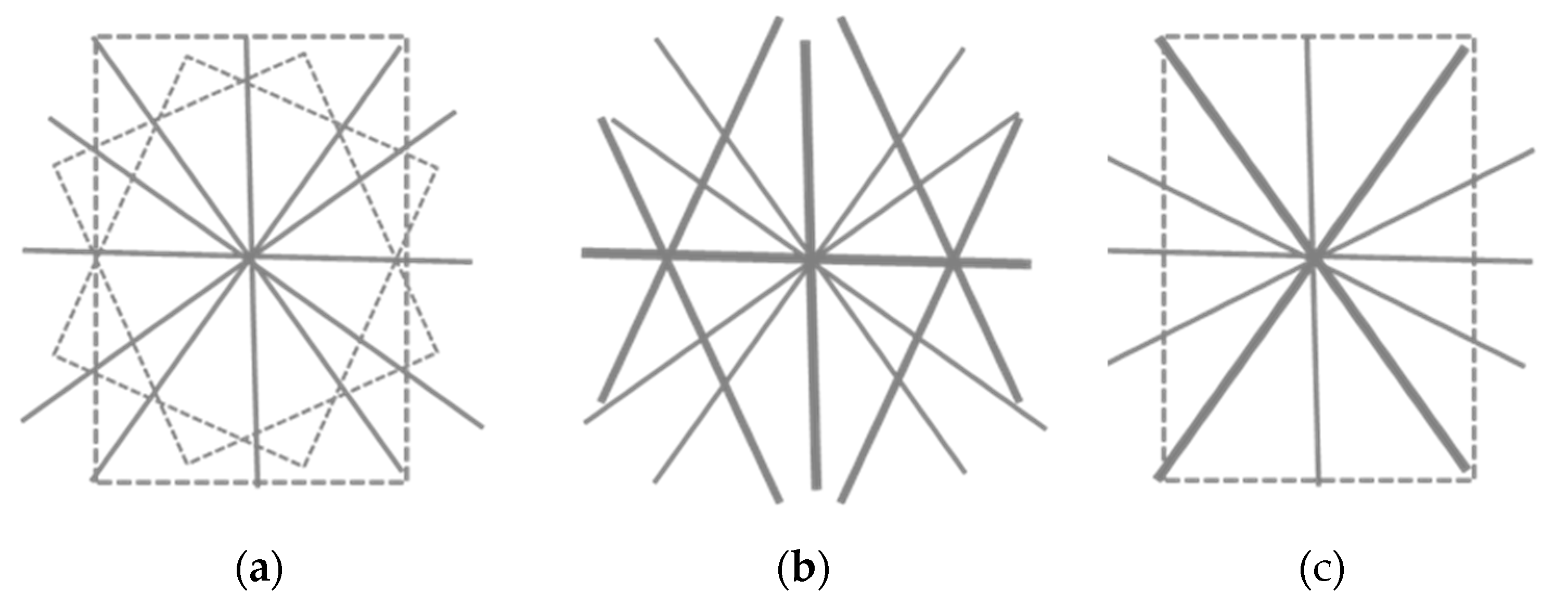
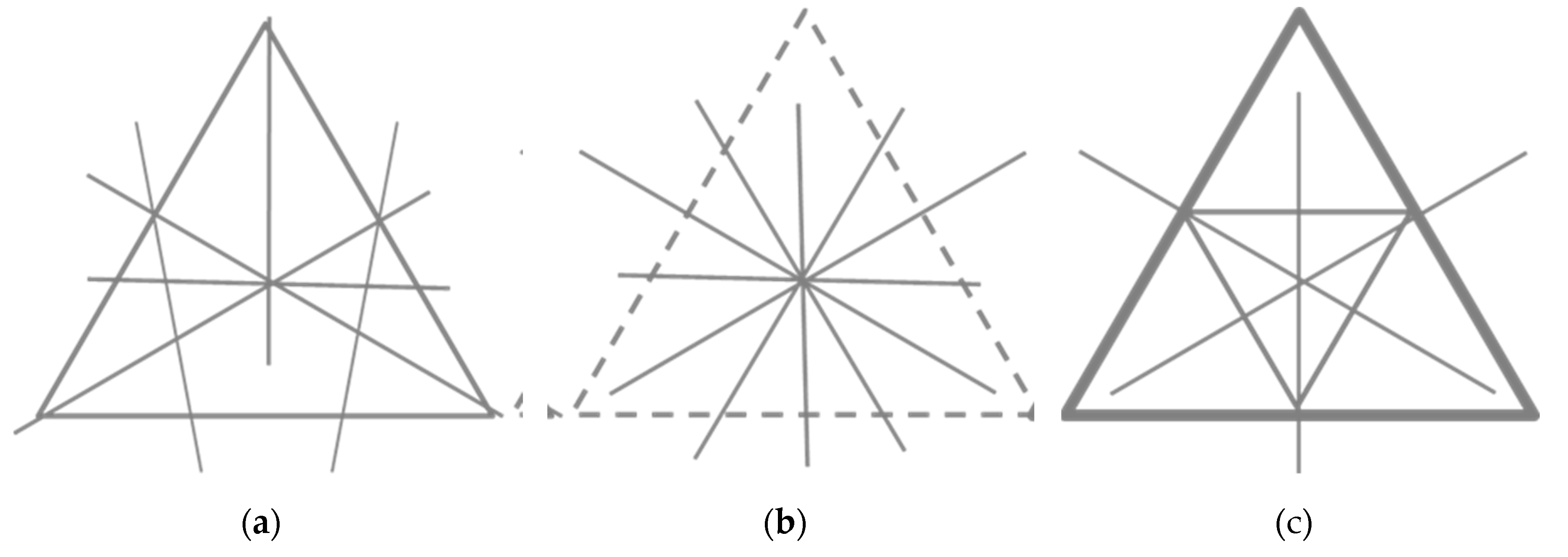
Along with surfaces, volumetric arrays may also produce the moiré effect [103]. For instance, we investigated the moiré effect in a discrete 3D object – a cube constructed from voxels (spheres of relatively small diameter) located at the nodes of cubic Bravais lattices (simple, body-, and face-centered), see Figure 11.
Corridors were observed in 3D cubes [104,105,106] as well as in the cubic lattice [107]. The distinctive angles of the corridors are independent of the lattice constant and the distance to the camera; therefore, the corridors pass through the entire volume of the cube. The widest corridors connect the anchor points (projections of the cube vertices); in the frontal camera; there are also perpendiculars to them. The main (and most noticeable) corridors are shown in Figure 12 for a simple cubic lattice.
Based on the rephrased definition [4] – the moiré effect is the formation of patterns of a longer period caused by a point-by-point interaction (interference) in corresponding points between projections of similar periodic structures of shorter periods and the averaging in the neighborhood of those points – we attribute these corridors to the moiré phenomenon, probably incomplete because of the lack of averaging due to a short distance.
The lattice itself produces the corridors, which have nothing to do with a useful image in a volumetric display. Therefore, in displays, such an undesirable effect (moiré corridors) should be eliminated.
Figure 12.
Moiré patterns and main corridors for a simple cubic lattice. Adapted from [108] under the terms and conditions of the Creative Commons Attribution (CC BY) license.
Figure 12.
Moiré patterns and main corridors for a simple cubic lattice. Adapted from [108] under the terms and conditions of the Creative Commons Attribution (CC BY) license.
A volumetric 3D display with static nodes [106,109,110,111] consists of light sources uniformly distributed in space along three coordinate axes. A volumetric LED cube is a set of square layers (non-twisted, non-coplanar matrices), see Figure 13. It represents a simple cubic lattice.
The physical display used in this research was a work of art (light sculpture “Pure Water”) [112] shown in Figure 3(a). The size of this physical display is approximately 6.3 x 6.3 x 10.5 m (18 x 18 x 30 LEDs). The voxel period is approximately 33 cm, the size is 3 cm; the distance to the camera was about 10-15 m.
In simulation, identical, identically oriented square layers represent the simple cubic lattice (matrices stacked into a cube). To simulate the body-centered lattice, a shifted layer was added between the planes, and for the face-centered lattice, two shifted layers (in the plane and between the planes) were added. The typical size of the simulated virtual object was 20x20x20 voxels; the voxel radius was about one-tenth the distance between them. Sometimes, we increased or decreased (the size of the cube in voxels), but the minimum thickness was 4 voxels (otherwise, the corridors do not appear).
The visual effect was considered for three camera positions: the camera facing the cube’s face, the edge, and the vertex. The axes of all cameras point to the cube’s center. The cameras and the crystallographic planes [113] perpendicular to the camera axes are shown in Figure 14.
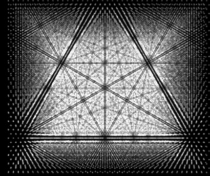
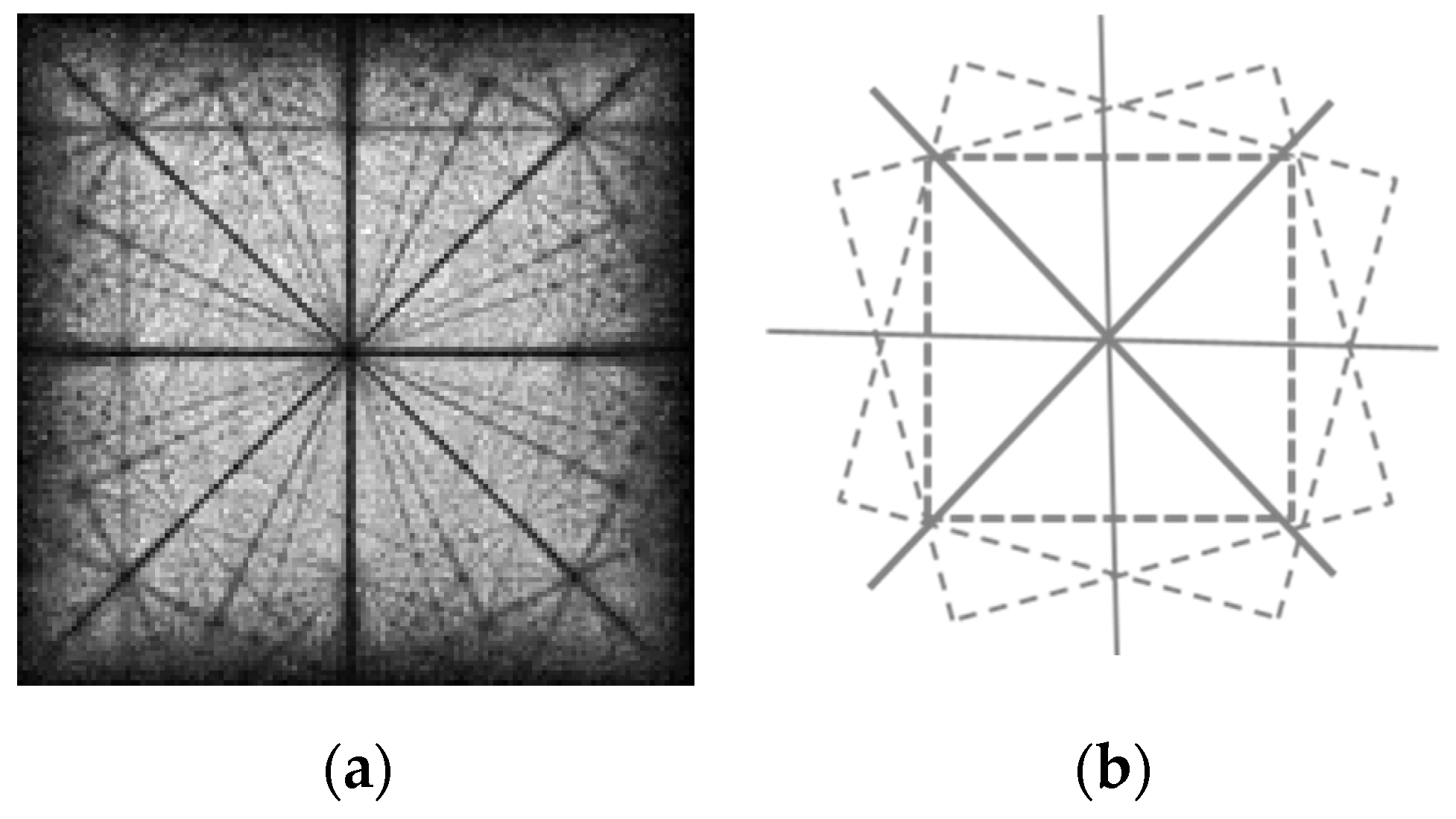
3.3.1. Moiré Patterns in Frontal Camera
The frontal camera with the axis perpendicular to the face of the cube is shown in Figure 15.
The planes perpendicular to the camera axis are parallel to the crystallographic plane (010). Each layer is a square grid. The observed moiré patterns and the basic structure of main corridors are shown in Figure 16 and Figure 17. The vertices of the cube closest to the camera are marked in Figure 16(a) with circles.
In the camera image, the main corridors are the radial rays with following distinctive angles [103],
Note that these angles only depend on the running integer numbers, but not on the distance or the lattice constant.
The radial corridors that start at the origin lie at the same angle in any layer; their structure is repeated in any layer, and thus the corridors “penetrate” through the volume of the cube. Therefore, the visual picture does not depend on lateral displacement; the overall visual appearance (corridors, angles between them, their relative positions, etc.) remains unchanged. The overlapped layers exhibit a distinct visual structure because the distinctive angles are independent of the geometric parameters.
There are also perpendiculars to the angles (7) that can be treated as non-radial corridors; these pass through other anchor points at the same angles, except the origin. As a result, we have several families of radial lines with rational tangents crossing the origin, plus the non-radial lines crossing anchor points.
The rise in moiré patterns can be schematically explained as follows. Due to differences in the apparent sizes of the layers, the voxel projections are grouped (clustered) and therefore arranged denser and sparser, as shown in Figure 18. The moiré patterns in a cube form “corridors” with different visual densities. A small difference in the apparent size of layers is enough to cause moiré patterns to clearly appear in a multi-layered 3D lattice. This effect is essentially multilayered and disappears when the number of layers is small.
The 2D spectrum (Fourier transform) of the frontal image is shown in Figure 19, where the radial line segments are clearly recognizable.
3.3.2. Edge Camera
The axis of the edge camera is perpendicular to the edge and points toward the cube’s center. The layer and voxels layout is shown in Figure 20.
The layers (planes perpendicular to the camera’s axis) are parallel to the crystallographic plane (110). The interlayer distance is a√2/2 (Figure 20(left)). The visible vertical and horizontal intervals between voxels in (110) are as follows: the interval a in the vertical direction and a√2 in the horizontal direction, as shown in Figure 20 (right). Thus, each plane perpendicular to the camera axis is a rectangular grid with an aspect ratio of √2. The “phase” of the neighboring planes is opposite (the phase difference is π).
Compared to the distance to the camera, the interlayer distance is relatively small, and therefore, to understand the visual effect, we can approximately merge the pairs of layers (two adjacent layers) into a single rectangular grid with an aspect ratio of √2/2 and the double interlayer distance of a√2, see Figure 21.
As a result, the approximate effective layout is a set of rectangular grids with an aspect ratio of √2. The interlayer distance between pairs is a√2. (One side is a, the other a/√2 vertically and a/√2 horizontally).
The structure of such paired layers is the same at any distance, and thus, the corridors also penetrate through the cube, as shown in Figure 22.
Figure 23.
Main moiré corridors in the edge camera. Reproduced from [108] under the terms and conditions of the Creative Commons Attribution (CC BY) license.
Figure 23.
Main moiré corridors in the edge camera. Reproduced from [108] under the terms and conditions of the Creative Commons Attribution (CC BY) license.
The corridor structures in the frontal and edge cameras near the origin are quite similar. The major difference between the images of the two cameras is in the “squeezed” angles of the edge camera,
The non-radial corridors are no longer perpendicular to the radial ones.
3.3.3. Vertex Camera
The vertex camera is located on the cube’s space diagonal. The planes perpendicular to the camera axis are parallel to the plane (111), as shown in Figure 24.
Here, the corridors differ significantly from the two previous cases because of non-orthogonal layout of planes. The planes perpendicular to the camera axis near the vertex comprise Pascal’s pyramid (Pascal’s tetrahedron) [114,115,116]. Each layer of Pascal’s pyramid is a triangular grid with the side of the triangle of a√2, where a is the lattice constant.
In this camera, the cross-sections can be considered by triplets with the phases differing by one-third of the period (a phase difference of 2π/3). For the visual effect, three merged successive layers can be approximately thought of as a triangular grid with a reduced side of a√2/√3 (as compared to the single cross-section) in the plane (111). The schematic picture is shown in Figure 25.
Similar to the edge camera, the above representation is approximately valid for the visual observation and simulation (= central projection). Then, the distinctive angles defined by triplets are identical. This means that in the vertex camera, as in the two previous cameras, the corridors also “penetrate” through the cube, however at different angles. In the regular triangular grid, the distinctive angles are arctan(√3/3), arctan(√3/5), arctan(√3/7), etc., i.e., 30°, 19.11°, 13.90°, etc. Therefore, the angles of the corridors are,
where s = 1, 2, …
The exact angle of 30⁰ gives rise to the triangular/hexagonal symmetry, see Figure 26. The general trend maintains: the repeated nodes on wider bands, with narrower bands connecting these and the intermediate nodes.
Figure 27.
Main moiré corridors. Reproduced from [108] under the terms and conditions of the Creative Commons Attribution (CC BY) license.
Figure 27.
Main moiré corridors. Reproduced from [108] under the terms and conditions of the Creative Commons Attribution (CC BY) license.
4. Discussion
In real layered displays, moiré waves with a 4th (and sometimes even a 5th) harmonic can be observed. The number of trajectories to be analyzed (a square number of components) is much higher than in the sinusoidal case. Thus, the simulation should be organized effectively.
Identical moiré periods were observed in planar hexagonal grids and in the chiral cylinders near the axis. This allows the moiré effect in chiral nanoparticles to be modeled using coplanar macroscopic bodies or by computer simulation. The physical model provides the experimental evidence; the computer simulation provides clear images of the moiré patterns. The moiré effect in MWNTs can also be simulated in a similar manner, treating the relative layer spacing as a small parameter.
The conditions for the moiré fringes to appear in the cubic lattice are: identical layers with identical spatial orientation (non-twist), with the voxel size √2 times smaller than the period, over four layers. In particular, to reduce moiré patterns in a volumetric 3D cube, the voxel diameter should be increased. (However, to observe the voxels with a larger diameter, the observation distance should be increased.)
The moiré effect in the cube can be”simu’ated in a parallelepiped with the same camera axis but a different voxel layout across the layers. Namely, the layers of the frontal camera remain unchanged. However, the layers of the edge camera form a parallelepiped with an aspect ratio of √2, the interlayer distance a/√2, and interlaced layers (phases 0 and π) can model the layers of the edge camera. Similarly, the layers of the vertex camera form a parallelepiped with a triangular grid, with sides of a√2, the interlayer distance of a/2, and interlaced triplets of layers (phases 0, π/3, and 2π/3). The results of the simulation of two cameras in the alternative (rectangular) layout are shown in Figure 28 and are similar to those presented in Sec. 3.
5. Conclusions
We demonstrated the combined simulation in three cases.
The parallel computer simulation and physical experiment layers ensure the minimization of the extended limited spectrum. The parameters of the moiré waves were measured semi-automatically in a simulation. The simulation tool is controlled interactively. The typical normalized RMS deviation between experiment and theory is 3-5%.
The moiré patterns can be observed in the chiral nanotubes at a large observer distance when m is greater than 10. The near-axis moiré effect in nanoparticles can be effectively modeled by macroscopic meshed bodies (planar printed grids or perforated metal ones) or computer files. The results can be applied to the moiré effect in meshed cylinders in general and to chiral nanoparticles in particular, for instance, to the measurement of chiral indices based on moiré images.
The moiré effect was investigated in a multi-layered simple cubic lattice using three cameras (directions [010], [110], and [111]). The moiré corridors were observed in simulation and in a physical volumetric display. The conditions for the appearance of moiré patterns were formulated. The corridors cross the anchor points at distinctive angles, which tangents in the three cameras are related as 1:√2:√3. These properties are observed in all three types of cubic lattices. (The corridors in the body- and face-centered lattices generally follow a simple lattice, but differ in width.) This research provides direct observation of the moiré effect in crystallographic planes, which can be useful in crystallography. The results can be used to minimize the moiré effect in volumetric 3D displays with fixed voxel positions, such as static LEDs.
Data Availability Statement
Data is contained within the article.
Abbreviations
The following abbreviations are used in this manuscript:
| 2D | two-dimensional |
| 3D | three-dimensional |
| SWNT | single-walled nanotube |
| DWNT | double-walled nanotube |
| MWNT | multiple-walled nanotube |
References
- Amidror, I. The Theory of the Moiré Phenomenon, Vol. I: Periodic Layers, 2nd ed,; Springer-Verlag, London, 2009.
- Sciammarella, C.A. The moiré method—A review. Exp. Mech. 1982, 22, 418–433. [CrossRef]
- Bryngdahl, O. Moiré: Formation and interpretation. J. Opt. Soc. Am. 1974, 64, 1287–1294. [CrossRef]
- Saveljev, V. The Geometry of the Moiré Effect in One, Two, and Three Dimensions; Cambridge Scholars: Newcastle Upon Tyne, UK, 2022.
- Saveljev, V. Moiré effect in 3D structures. In Advances in Optics: Reviews; Yurish, S.Y., ed.; Barcelona, Spain: International Frequency Sensor Association Publishing, 2018, vol. 1, pp. 61-93.
- Saveljev, V.; Kim, S.-K. Simulation of moiré effect in 3D displays. J. Opt. Soc. Korea 2010, 14, 310-315. [CrossRef]
- Sciammarella, C.A.; Chiang, F.-P. Gap effect on moiré patterns. ZAMP 1968, 19,326–333. [CrossRef]
- Saveljev, V.; Kim, S.-K. Simulation and measurement of moiré patterns at finite distance. Opt. Express 2011, 20, 2163-2177. [CrossRef]
- Saveljev, V.; Son, J.-Y.; Kim, Y.; Park, J.-G.; Heo, G. Moiré patterns in non-parallel surfaces such as prism. JOSA A 2020, 37(2), 336-345. [CrossRef]
- Saveljev, V.; Han, W.; Lee, H.; Kim, J.; Kim, J. Moiré effect in double-layered coaxial cylinders. Appl. Opt. 2020, 59(18), 5596-5607. [CrossRef]
- Saveljev, V.; Lee, H.; Kim, J. Physical Model of the Moiré Effect in Cylindrical Structures. J. Korean Phys. Soc. 2017, 71, 934-945. [CrossRef]
- Saveljev, V. Moiré effect in cylindrical objects. J Korean Phys. Soc. 2016, 68, 9, 1075-1082. [CrossRef]
- Saveljev, V. The off-axis moiré effect in double-layered cylinder. J. Mod. Opt. 2023, 70(1), 39-51. [CrossRef]
- Saveljev V.; Heo, G. Moiré effect in combined planar and curved objects. JOSA A 2024, 41(10), 1884-1892. [CrossRef]
- Kong, L.; Jin, G.; Wang, T. Analysis of moiré minimization in autostereoscopic parallax displays. Opt. Express 2013, 21(22), 26068–26079. [CrossRef]
- Bell, G.; Craig, R.; Simmiss, T. Moiré interference in multilayered displays. J. Soc. Inf. Disp. 2007, 15(11), 883–888. [CrossRef]
- Blatner, D.; Roth, S.F. Real World Scanning and Halftones, 3rd ed.; Peachpit, Berkeley, California, 2004.
- Saveljev V. Moiré in dimensions. Available online: https://moire7.wordpress.com/ (2024).
- Dohnal, M. Moiré in a scanned image. Proc. SPIE 1999, 4016, 166–170.
- Saveljev, V.; Kim, S.-K.; Kim, J. Moiré effect in displays: a tutorial. Opt. Eng. 2018, 57(3), 030803. [CrossRef]
- Saveljev V.; Kim, S.-K. Amplitude, period and orientation of the moiré patterns in barrier 3D displays. J Inf. Disp. 2018, 19(2), 81-90. [CrossRef]
- Saveljev V.; Kim, S.-K. Controlled moiré effect in multiview three-dimensional displays: image quality and image generation. Opt. Eng. 2018, 57(6), 061623. [CrossRef]
- Saveljev V.; Kim S.-K. Experimental observation of moiré angles in parallax barrier 3D displays. Opt. Express 2014, 22, 17147-17157. [CrossRef]
- Lee, B.; Park, S.-G.; Hong, K.; Hong, J. Design and Implementation of Autostereoscopic Displays. SPIE, Bellingham, Washington, 2016.
- Gao, Y.; Li, P.; Gong, F.; Zhai, S.; Wang, C.; Zhao, L Research on reducing moiré patterns in nakedeye 3d displays through optimizing lenticular lens tilt angle, Proc. International Conference on Display Technology, Hefei, Anhui, China, 55(S1), 729-733 (2024).
- Yurlov, V.; Kim, T.Y.; Han, K.; Yu, N.E.; Kim, Y.-J.; Pournoury, M. Visibility minimization of the moiré pattern on a display screen by optimizing geometrical parameters using an F/θ plot. JOSA B 2018, 35(10), 2562-2573. [CrossRef]
- Qi, W.; Yu, X.; Li, X.; Kang; S. A moiré removal method based on peak filtering and image enhancement. Mathematics 2024, 12(6), 846. [CrossRef]
- Kim, J.-H.; Kong, K.; Kang, S.-J. Image demoireing via u-net for detection of display defects. IEEE Access 2022, 10, 68645- 68654. [CrossRef]
- Sun, Y.; Yu, Y.; Wang, W. Moiré photo restoration using multiresolution convolutional neural networks. IEEE Trans. Image Process. 2018, 27(8), 4160-4172. [CrossRef]
- Yue, H.; Cheng, Y.; Liu, F.; Yang, J. Unsupervised moiré pattern removal for recaptured screen images. Neurocomputing 2021, 456, 352–363. [CrossRef]
- Xia, X.; Zhuang, X.; He, H.; Wu, X.; Zheng H.; Yu, Y. Moiré-free and high-resolution light field 3D display based on random parallax barrier. J. Phys. Photonics 2025, 7, 035009. [CrossRef]
- Fukano, K.; Yura, T.; Takaki, Y. Moiré reduction technique for near-virtual-image-mode light field displays via aperture array modification. Appl. Sci. 2025, 15(20), 11031. [CrossRef]
- Saunoriene, L.; Saunoris, M.; Ragulskis, M. Image hiding in stochastic geometric moiré gratings. Mathematics 2023, 11(8), 1763. [CrossRef]
- Cadarso, V.J.; Chosson, S.; Sidler, K.; Hersch, R.D.; Brugger, J. High-resolution 1D moirés as counterfeit security features. Light Sci. Appl. 2013, 2, e86. [CrossRef]
- Post, D.; Han, B.; Ifju, P. High Sensitivity Moiré: Experimental Analysis for Mechanics and Materials; Springer: New York, NY, USA, 1994.
- Kafri, O.; Band, Y.B.; Chin, T.; Heller, D.F.; Walling, J.C. Real-time moiré vibration analysis of diffusive objects. Appl. Opt. 1985, 24, 240–242. [CrossRef]
- Yang, C.; Yang, Z.; Ke, Y.; Chen, T.; Grzegorzek, M.; Se, J. Doing more with moiré pattern detection in digital photos. IEEE Trans. Image Proc. 2023, 32, 694-708. [CrossRef]
- Jeong, H.I.; Choi, S.Y.; Jeong, Y.J. Measurement of moiré patterns in 3D display. Proc. IDW, vol. 26, 2019, 986-988.
- Wang, Q.; Ri, S.; Tsuda, H. Digital sampling moiré as a substitute for microscope scanning moiré for high-sensitivity and full-field deformation measurement at micron/nano scales. Appl. Opt. 2016, 55(25), 6858-6865. [CrossRef]
- Patorski, K.; Kujawinska, M. Handbook of the Moiré Fringe Technique; Elsevier: London, UK, 1993.
- Kafri, O.; Glatt, I. The Physics of Moiré Metrology; Willey and Sons: New York, NY, USA, 1990.
- Theocaris, P.S. Moiré Fringes in Strain Analysis; Pergamon Press: London, UK, 1969.
- Saveljev, V. Various grids in moiré measurements. Metrology 2024, 4(4), 619-639. [CrossRef]
- Sadan, M.B.; Houben, L.; Enyashin, A.N.; Seifert, G.; Tenne, R. Atom by atom: HRTEM insights into inorganic nanotubes and fullerene-like structures. PNAS 2008, 105, 15643–15648. [CrossRef]
- Warner, J.H.; Young, N.P.; Kirkland, A.I.; Briggs, G.A.D. Resolving strain in carbon nanotubes at the atomic level. Nat. Mater. 2011, 10, 958–962. [CrossRef]
- N’Diaye, A.T.; Bleikamp, S.; Feibelman, P.J.; Michely, T. Two-dimensional Ir cluster lattice on a graphene moiré on Ir(111). Phys. Rev. Lett. 2006, 97 (21): 215501. [CrossRef]
- Suenaga, K.; Wakabayashi, H.; Koshino, M.; Sato, Y.; Urita, K.; Iijima, S. Imaging active topological defects in carbon nanotubes. Nat, Nanotechnol, 2007, 2 (6): 358. [CrossRef]
- Fukui, N.; Suwa, Y.; Yoshida, H.; Sugai, T.; Heike S.; Fujimori, M.; Terada, Y.; Hashizume, T.; Shinohara, H. Moiré image patterns on double-walled carbon nanotubes observed by scanning tunneling microscopy. Phys. Rev. B 2009, 79, 125402. [CrossRef]
- Bassett, G.A.; Menter, J.W.; Pashley, D.W. Moiré patterns on electron micrographs, and their application to the study of dislocations in metals. Proc. Royal Soc. London 1958, 256 (1246), 345-368.
- Benedict, L.X.; Chopra, N.G.; Cohen, M.L.; Zettl, A.; Louie, S.G.; Crespi. V.H. Microscopic determination of the interlayer binding energy in graphite. Chem. Phys. Lett. 1998, 286 (5-6): 490-496. [CrossRef]
- Zhou, X.; Xie, J.; Li, G.; Zhang, J.; Xia, M.; Luo, W.; Shi, Z. Moiré-induced band-gap opening in one-dimensional superlattices of carbon nanotubes on hexagonal boron nitride. Phys. Rev. B 2022, 105, 115433. [CrossRef]
- Konevtsova, O.V.; Roshal, D.S.; Rochal, S.B. Moiré patterns and carbon nanotube sorting. Nano Futures 2022, 6, 015005. [CrossRef]
- Tu, J.F. TEM nano-moiré pattern analysis of a copper/single walled carbon nanotube nanocomposite synthesized by laser surface implanting. C 2018, 4(1), 19. [CrossRef]
- Arroyo-Gascón, O.; Fernández-Perea, R.; Suárez Morell, E.; Cabrillo, C.; Chico, L. Universality of moiré physics in collapsed chiral carbon nanotubes. Carbon 2023, 205, 394-401. [CrossRef]
- N. Wittemeier, M.J. Verstraete, P. Ordejon, Z. Zanolli, Interference effects in one-dimensional moiré crystals. Carbon 2022, 186, 416-422. [CrossRef]
- M. He, Z. Xu, D. Shang, X. Zhang, H. Zhang, D. Li, H. Jiang, E. Kauppinen, F. Ding, Is there chiral correlation between graphitic layers in double-wall carbon nanotubes? Carbon 2019, 144, 147-151. [CrossRef]
- Wang, S.; Song, J.; Sun, M.; Cao, S. Emerging characteristics and properties of moiré materials. Nanomaterials 2023, 13(21), 2881. [CrossRef]
- Khurana, R.K. Moiré patterns in nanomaterials. Mat. Sci. Semicon. Proc. 2022, 140, 106406. [CrossRef]
- Arrighi, E.; Nguyen, V.-H.; Di Luca, M.; Maffione, G.; Hong, Y.; Farrar, L.; Watanabe, K.; Taniguchi, T.; Mailly, D.; Charlier J.-C.; Ribeiro-Palau, R. Non-identical moiré twins in bilayer graphene. Nat. Comm. 2023, 14, 8178. [CrossRef]
- de Jong, T.A.; Benschop, T.; Chen, X.; Krasovskii, E.E.; de Dood, M.J.A.; Tromp, R.M.; Allan M.P.; van der Molen, S.J. Imaging moiré deformation and dynamics in twisted bilayer graphene. Nat. Comm. 2022, 13, 70. [CrossRef]
- Dindorkar, S.S.; Kurade, A.S.; Shaikh, A.H. Magical moiré patterns in twisted bilayer graphene: A review on recent advances in graphene twistronics. Chem. Phys. Impact 2023, 7, 100325. [CrossRef]
- Latychevskaia, T.; Escher, C.; Fink, H.-W. Moiré structures in twisted bilayer graphene studied by transmission electron microscopy. Ultramicroscopy 2019, 197, 46-52. [CrossRef]
- Luo, Y.; Engelke, R.; Mattheakis, M.; Tamagnone, M.; Carr, S.; Watanabe, K.; Taniguchi, T.; Kaxiras, E.; Kim, P.; Wilson, W. L. In situ nanoscale imaging of moiré superlattices in twisted van der Waals heterostructures. Nat. Comm. 2020, 11, 4209. [CrossRef]
- Bistritzer R.; MacDonald, A.H. Moiré bands in twisted double-layer graphene. PNAS 2011, 108(30), 12233-12237. [CrossRef]
- Yu, Y.; Van Winkle, M.; Bediakoa, D.K.; Tuning Interfacial Chemistry with Twistronics. Trends Chem. 2022, 4(10), 857-859. [CrossRef]
- Wu, D.; Pan, Y.; Min, T. Twistronics in graphene, from transfer assembly to epitaxy. Appl. Sci. 2020, 10(14), 4690. [CrossRef]
- Hennighausen, Z.; Kar, S. Twistronics: A turning point in 2D quantum materials. Electron. Struct. 2021, 3, 014004. [CrossRef]
- Hu, G.; Qiu, C.-W.; Alù, A. Twistronics for photons: opinion. Opt. Mater. Express 2021, 11(5), 1377-1382. [CrossRef]
- Carr, S.; Massat, D.; Fang, S.; Cazeaux, P.; Luskin, M.; Kaxiras, E. Twistronics: Manipulating the electronic properties of two-dimensional layered structures through their twist angle. Phys. Rev. B 2017, 95, 075420. [CrossRef]
- Ren, W.; Zhu, Z.; Zhang, X.; Luskin, M.; Wang, K. Review: moiré-of-moiré superlattice in twisted trilayer graphene. J. Phys.: Condens. Matter 2025, 37, 353001. [CrossRef]
- Xu, P.; Qi, D.; Schoelz, J.K.: Thompson, J.; Thibado, P.M.; Wheeler, V.D.; Nyakiti, L.O.; Myers-Ward, R.L.; Eddy Jr., C.R.; Gaskill, D.K.; Neek-Amal, M.; Peeters, F.M. Multilayer graphene, moiré patterns, grain boundaries and defects identified by scanning tunneling microscopy on the m-plane, non-polar surface of SiC. Carbon 2014, 80, 75-81. [CrossRef]
- Guo, C.; Zhang, Q.; Ji, J.; Yang, L.; Xie, H. Moiré fringes simulation in liquid crystal display. Acta Opt. Sin. 2022, 42(20), 2012004.
- Kim, Y.; Park, G.; Jung, J.-H.; Kim, J.; Lee, B. Color moiré pattern simulation and analysis in three-dimensional integral imaging for finding the moiré-reduced tilted angle of a lens array. Appl. Opt. 2009, 48(11), 2178-2187. [CrossRef]
- Li, K.; Zhou, Y.; Pan, D.; Ma, X.; Ma, H.; Liang, H.; Zhou, J. Global control of colored moiré pattern in layered optical structures. Opt. Comm. 2018, 414, 154-159. [CrossRef]
- Byun, S.-J.; Byun, S.Y.; Lee, J.; Kim, W.M.; Kim, H.-P.; Jeon, M.Y.; Lee, T.-S. An efficient simulation and analysis method of moiré patterns in display systems. Opt. Express 2014, 22(3), 3128-3136. [CrossRef]
- Joo, B.-Y.; Shin, D.-H. Simulations of pixel moirés in the liquid crystal display with image processing technique. Displays 2009, 30(4–5), 190-194. [CrossRef]
- Joo, B.-Y.; Ko, J.-H. Simulation study on the minimization of moiré patterns caused by microlens array films for backlight applications. J. Opt. Soc. Korea 2014, 18(5), 538-545. [CrossRef]
- Qu, C.; Huang, J.; Lu, Z. A new simulation method for moiré control of LED background screen in film and television shooting. Proc. SPIE 2023, 12935, 129352D.
- Pournoury, M.; Zamiri, A.; Yurlov, V.; Kim, T.Y.; Jung, A.; Oh, K. Minimization of moiré effect generated by a double-layered metal mesh on top of the R-G-B optical source. Results Phys. 2019, 14, 102401. [CrossRef]
- Xie, X.; Hong, Y.; Shao, X.; Guo, Z.; Lei, Z; Xu, Z.; Jing, W.; Min, H; Xu, S. Moiré research and simulation of OGS metal mesh touch sensor. SID Digest 2018, 1889- 1892. [CrossRef]
- Su, Y.; Wang, Z.; An, D. Simulation of moiré pattern based on transmittance calculation of LCD metal mesh touch panel. J. Soc. Inf. Disp. 2021, 29, 620–631. [CrossRef]
- Xu, J.; Zhang, Q.; Li, H.; Liu, T.; Chen, S.; Shang, F. Simulation of color moiré pattern in LCD-based metal mesh touch screen. SID Digest 2017, 2087- 2090. [CrossRef]
- Wegdam, A.M.; Podzimek, O.; Hallie, H. Projection moiré system simulation. Appl. Opt. 1992, 31(19), 3755-3758. [CrossRef]
- Buytaert, J.A.N.; Ribbens, B.; Vanlanduit, S.; Dirckx, J.J.J. Aberration-free moiré profilometry—Analysis, simulation and implementation of the optimal setup geometry. Opt. Laser Eng. 2012, 50(8), 1119-1129. [CrossRef]
- Mol, F.; Simulating TV moiré pattern. Available online: https://creativecow.net/forums/thread/simulating-tv-moire-pattern/ (2012).
- Hsu, B. Moiré pattern simulator. Available online: https://github.com/BogiHsu/Moire-Pattern-Simulator (2018).
- Zhang, S. VirtualLab Fusion: A physical optics simulation platform. Proc. SPIE 2020, OP20EX0G.
- Aleksa, A.; Petrauskiene, V.; Ragulskis, M. Stochastic Time-Averaged Moiré Fringes. Wolfram Demonstrations Project. Demonstrations. Available online: wolfram.com/StochasticTimeAveragedMoireFringes/ (2011).
- Stephens, T. Moiré pattern simulator. Hollen Lab. Available online: https://unh2d.weebly.com/moire-pattern-simulator.html 1/ (2017).
- Soejima, T.; Parker, D.E.; Bultinck, N.; Hauschild, J.; Zaletel1, M.P. Efficient simulation of moiré materials using the density matrix renormalization group. Phys. Rev. B 2020, 102, 205111. [CrossRef]
- Zhu Z.B.; Hou, Y.; Wu, H.A.; Zhu, Y.B. Bending moiré in twisted bilayer graphene. J. Phys. Chem. Lett. 2024, 16(1), 45-52. [CrossRef]
- Xiao, Y.; Liu, J.; Fu, L.Moiré is more: access to new properties of two-dimensional layered materials. Matter 2020, 3(4), 1142-1161. [CrossRef]
- Zhang, C.; Chuu, C.-P.; Ren, X.; Li, M.-Y.; Li, L.-J.; Jin, C.; Chou, M.-Y.; Shih, C.-K. Interlayer couplings, moiré patterns, and 2D electronic superlattices in MoS2/WSe2 hetero-bilayers. Sci. Adv. 2017, 3(1), 1-7. [CrossRef]
- Li, Quasiperiodic moiré reconstruction and modulation of electronic properties in twisted bilayer graphene aligned with hexagonal boron nitride. Phys. Rev. Lett. 2024, 133, 196401. [CrossRef]
- Zhang, S.; He, D.; Huang, P.; Wang, F. Moiré pattern at graphene/Al (111) interface: experiment and simulation. Mat.Design 2021, 201, 109509. [CrossRef]
- Pochet, P.; McGuigan, B.C.; Coraux, J.; Johnson, H.T. Toward moiré engineering in 2D materials via dislocation theory. Adv. Mat. Today 2017, 9, 240-250. [CrossRef]
- Ascrizzi, E.; Goniakowski, J.; Yang, J.; Agnoli, S.; Ferrari, A.M. DFT study of the moiré pattern of FeO monolayer on Au(111). Phys. Chem. Chem. Phys. 2024, 29, 20103–20111. [CrossRef]
- Tang, Y.; Li, L.; Li, T.; Xu, Y.; Liu, S.; Barmak, K.; Watanabe, K.; Taniguchi, T.; MacDonald, A.H.; Shan, J.; Mak, K.F. Simulation of Hubbard model physics in WSe2/WS2 moiré superlattices. Nature 2020, 579,353–358. [CrossRef]
- Saveljev V.; Kim S.-K. Theoretical estimation of moiré effect using spectral trajectories. Opt. Express 2013, 1693-1712. [CrossRef]
- Saveljev V.; Kim S.-K. Estimation of moiré patterns using spectral trajectories in the complex plane. CTA 2012, 3, 353-360.
- Saveljev, V.; Kim, S.-K. Computer simulation of moiré waves in autostereoscopic displays basing on spectral trajectories. Proc. SPIE 2014, 9117, 91170W, Baltimore, MD, USA.
- Vpython. Available online: https://vpython.org/. (2020).
- Saveljev, V. Moiré effect in multilayered 3D lattice. Appl. Opt. 2023, 62, 2792-2799. [CrossRef]
- Wyatt, D.; Wujanto, L. A volumetric 3D LED display. MIT 6.111: Introductory Digital Systems Laboratory, 2005 (Final project report).
- Rowe, A. Within an ocean of light: creating volumetric lightscapes. Leonardo 2012, 45, 358–365. [CrossRef]
- ETERESHOP, High-density Smart 3D LED Cube with 16k LEDs _P42. Available online: https://www.etereshop.com/product/high-density-smart-3d-led-cube-with-16k-leds/ (2025).
- Weisstein, E. W. Cubic lattice. From MathWorld – A Wolfram Web Resource. Available online: https://mathworld.wolfram.com/CubicLattice.html (2020).
- Saveljev V.; Heo, G. Simulation of the moiré effect in cubic Bravais lattices. Proc. 11th International Congress on Global Practice of Multidisciplinary Scientific Studies, Munich, Germany, 2025, pp. 1531-1535.
- Lidbeck, J. Euclid’s (zero-gravity) orchard. Available online: https://www.flickr.com/photos/jondissed/37799943964 (2020).
- Particulate – sketches. Available online: https://vimeo.com/81991904 (2020).
- Frances, H. Kaleidoscope of possibility. Available online: https://architecturenow.co.nz/articles/kaleidoscope-of-possibility/ (2013).
- Light sculpture Pure water. Yuseong News 2022, 192, p. 9. http://pdf.yuseongnews.co.kr/192/19201.pdf.
- Giacovazzo, C.; Monaco, H.L.; Artioli, G.; Viterbo, D.; Ferraris, G.; Gilli, G.; Zanotti, G.; Catti, M.; Fundamentals of Crystallography, 2nd ed.; Oxford University, 1992.
- Pascal’s pyramid. Available online: https://en.wikipedia.org/wiki/Pascal%27s_pyramid (2020).
- Duczek, S.; Duvigneau, F.; Gabbert, U. The finite cell method for tetrahedral meshes. Finite Elem. Anal. Des. 2016, 121, 18–24. [CrossRef]
- Natingga, D. Pascal’s tetrahedron. Available online: https://davidnatingga.wordpress.com/2018/03/11/pascals-tetrahedron/ (2018).
Figure 2.
Simulation tool. (a) outline mode, (b) detail mode.
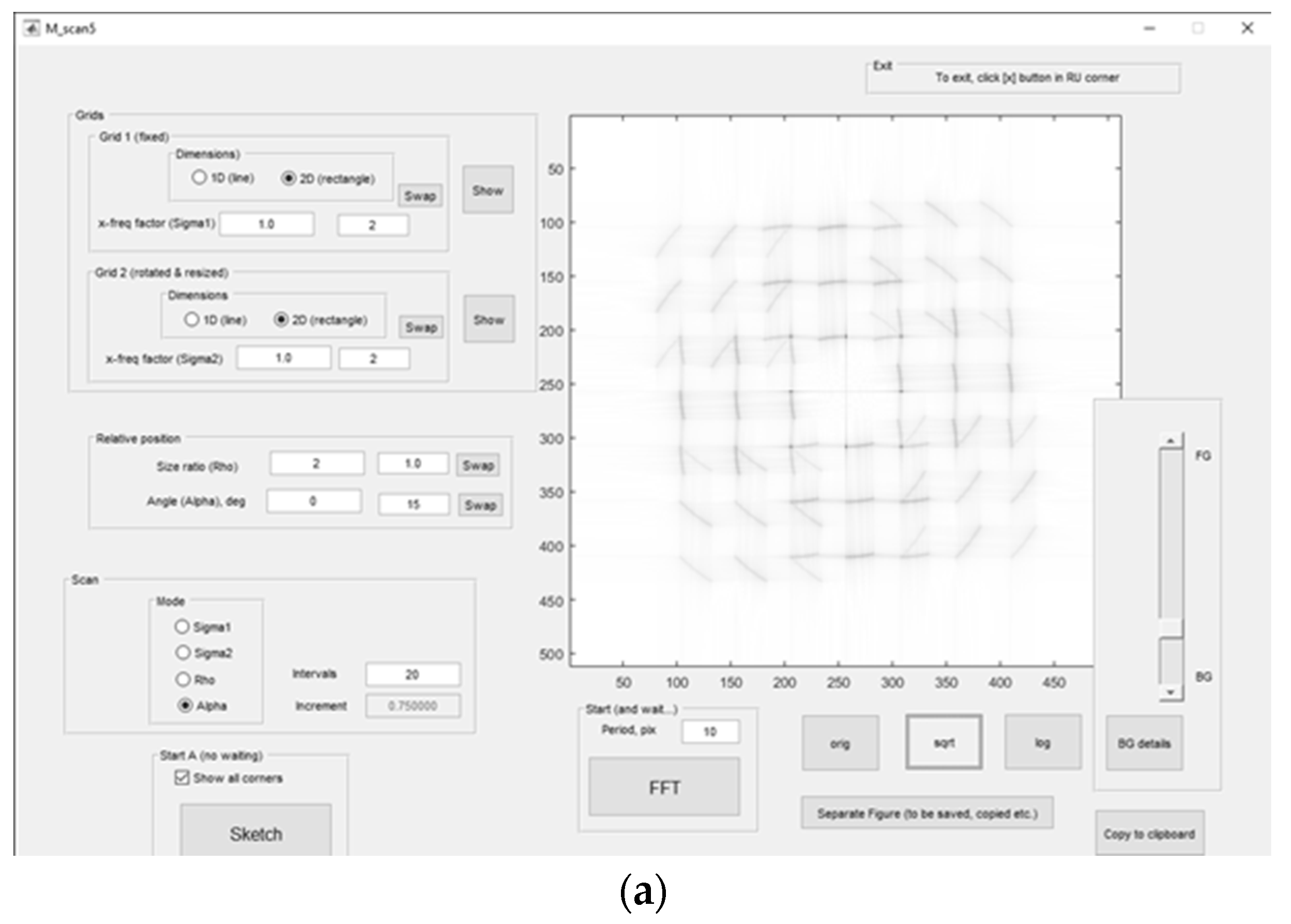
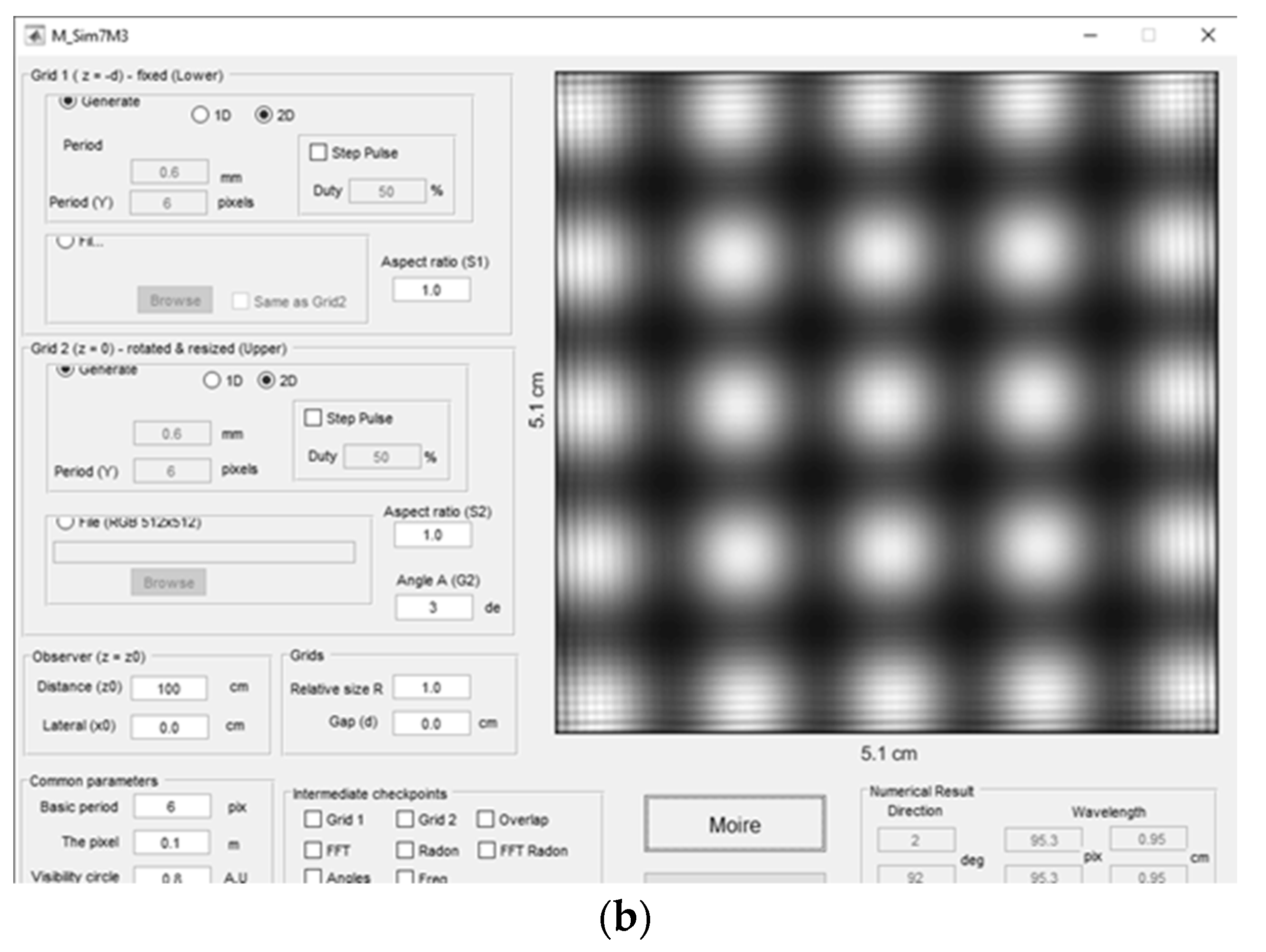
Figure 3.
(a) Photograph of the overall layout of the physical object (LED cube). (b) Screenshot of computer simulation with the image of the frontal camera (see Sec 3.1). Adapted from [103] with permission.
Figure 3.
(a) Photograph of the overall layout of the physical object (LED cube). (b) Screenshot of computer simulation with the image of the frontal camera (see Sec 3.1). Adapted from [103] with permission.
Figure 4.
Spectral trajectories with 3 harmonics (non-sinusoidal profile) for ρ = 1.2 (simulation). Reproduced from [101] with permission.
Figure 4.
Spectral trajectories with 3 harmonics (non-sinusoidal profile) for ρ = 1.2 (simulation). Reproduced from [101] with permission.
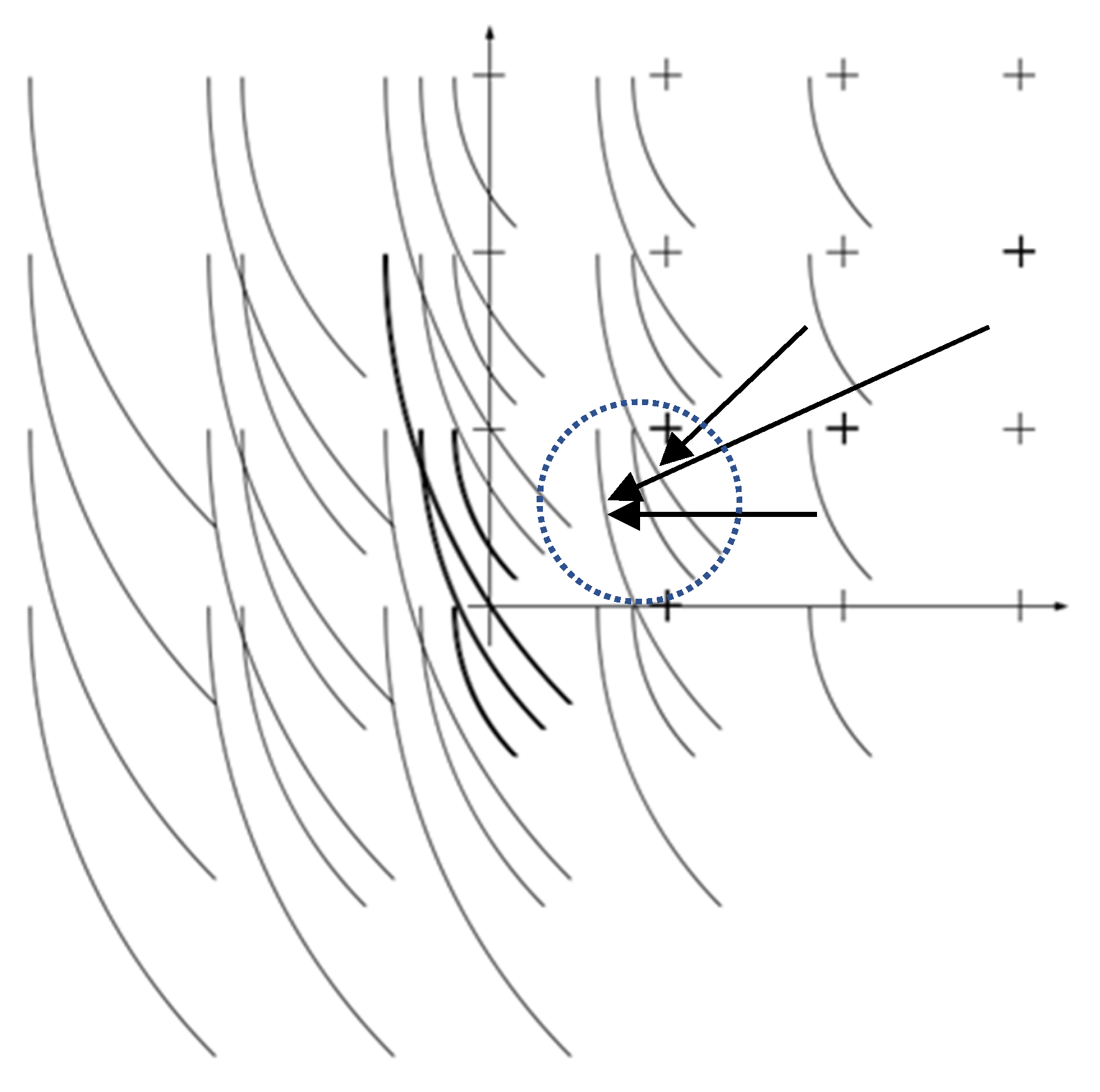
Figure 5.
Experimentally observed moiré patterns for ρ = 1.2 at 0, 27°, and 45°. Reproduced from [101] with permission.
Figure 5.
Experimentally observed moiré patterns for ρ = 1.2 at 0, 27°, and 45°. Reproduced from [101] with permission.
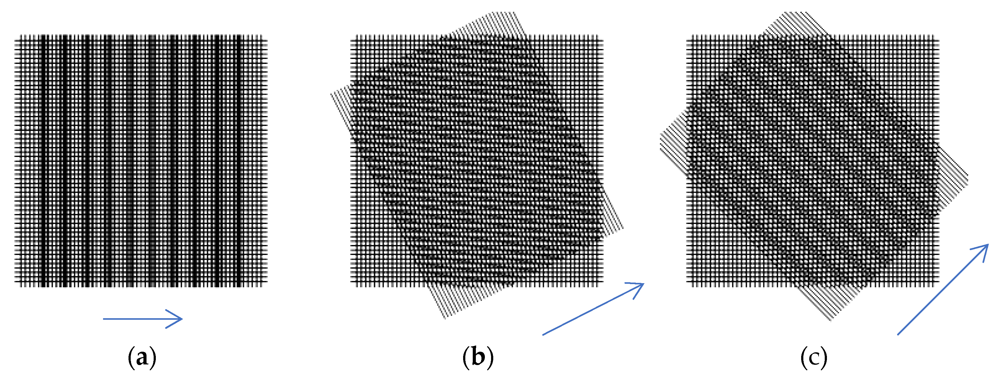
Figure 6.
Photographs of chiral cylinder (line grid with a period 0.1 mm and angle = 2.5° at L = 200. Chiral cylinders (hexagonal mesh, chiral angles 5° and 2.5°), L = 200. Reproduced from [11] with permission.
Figure 6.
Photographs of chiral cylinder (line grid with a period 0.1 mm and angle = 2.5° at L = 200. Chiral cylinders (hexagonal mesh, chiral angles 5° and 2.5°), L = 200. Reproduced from [11] with permission.
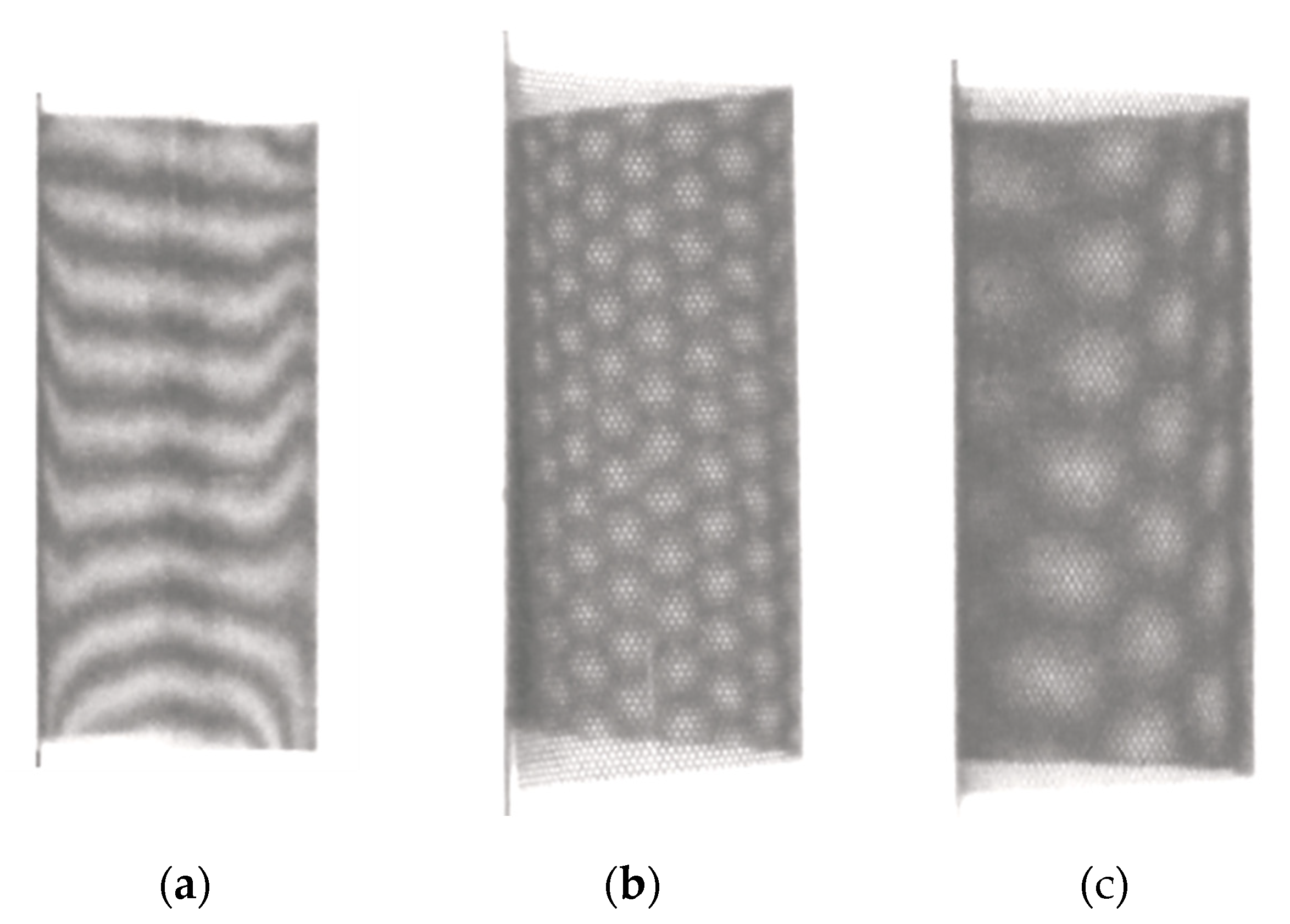
Figure 7.
(a). Photograph of identical planar line grids with a period 0.1 mm and α = 2.5°. (b) Computer files for the same conditions. Reproduced from [11] with permission.
Figure 7.
(a). Photograph of identical planar line grids with a period 0.1 mm and α = 2.5°. (b) Computer files for the same conditions. Reproduced from [11] with permission.

Figure 8.
(a) and (b) Photographs of planar coplanar hexagonal grids a period 2.54 mm; angles (double chiral angles) are 10° and 5°. (c), (d) Simulated moiré patterns (superimposed computer files) for the same angles. Reproduced from [11] with permission.
Figure 8.
(a) and (b) Photographs of planar coplanar hexagonal grids a period 2.54 mm; angles (double chiral angles) are 10° and 5°. (c), (d) Simulated moiré patterns (superimposed computer files) for the same angles. Reproduced from [11] with permission.
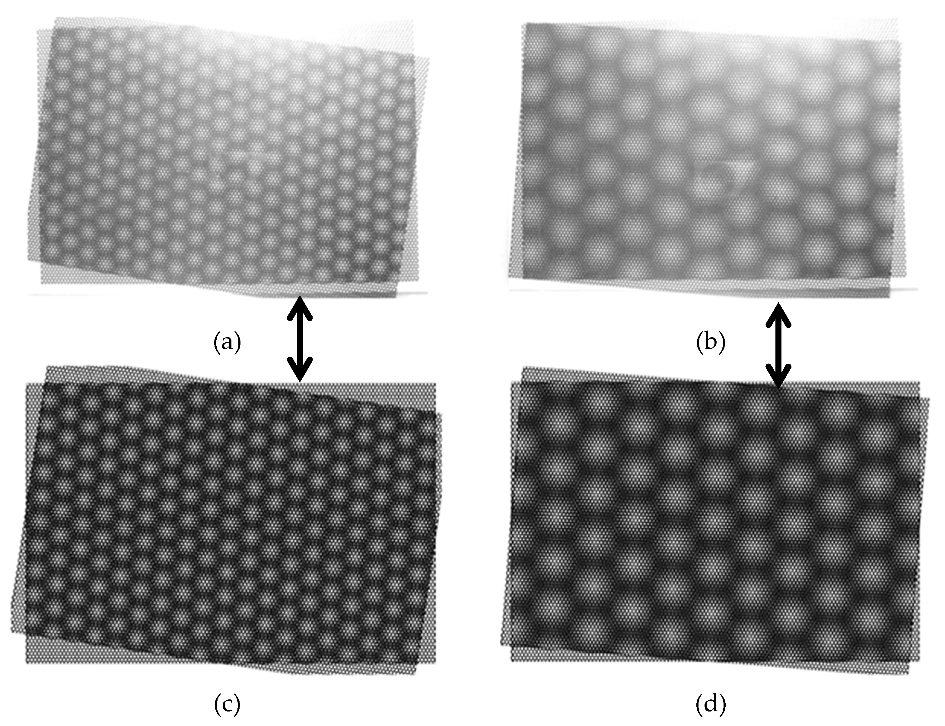
Figure 9.
(a) Schematic image of a wired sphere. (b) Moiré effect in sphere (photograph). Reproduced from [4].
Figure 9.
(a) Schematic image of a wired sphere. (b) Moiré effect in sphere (photograph). Reproduced from [4].
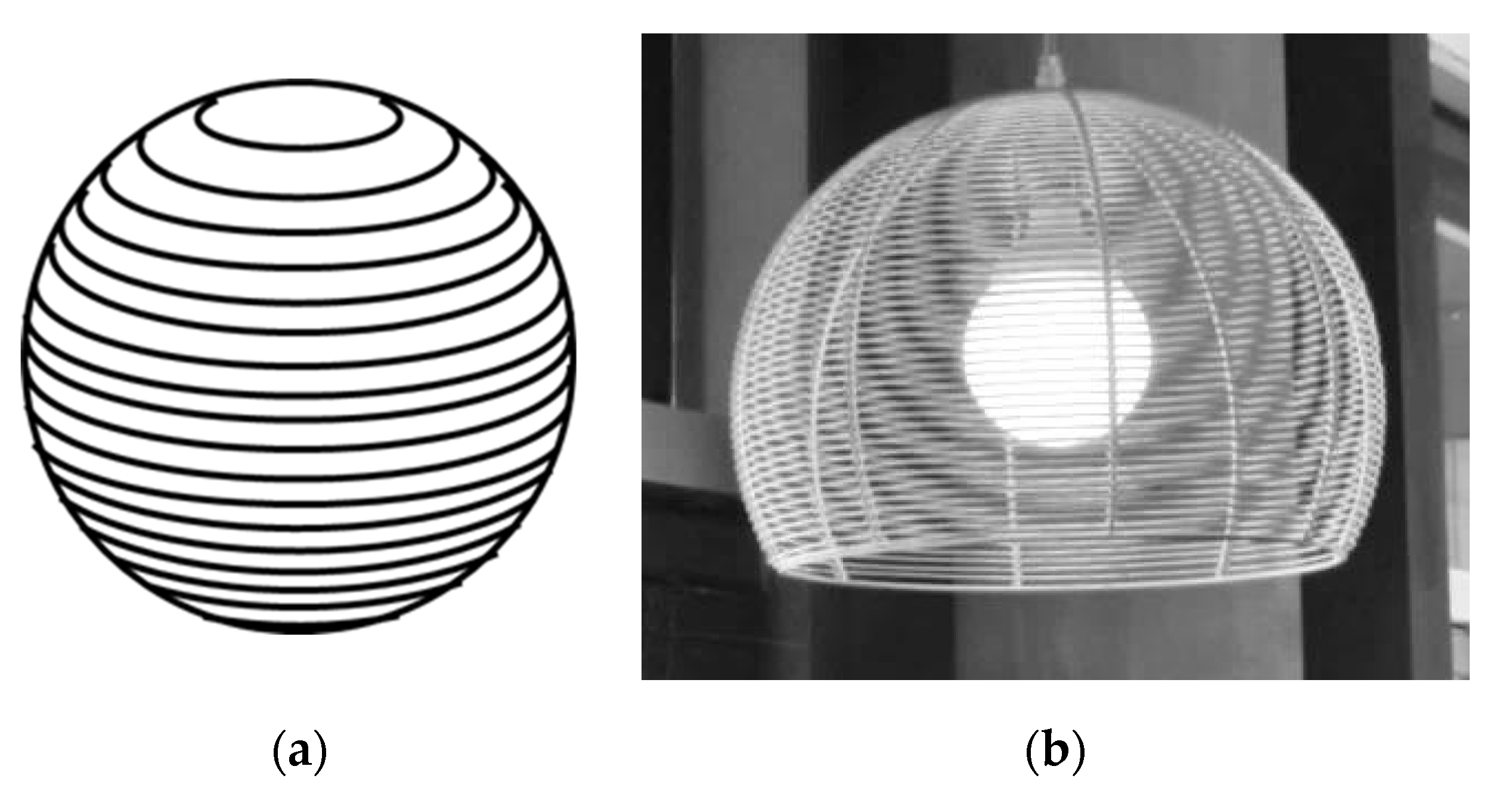
Figure 10.
Moiré patterns in a sphere made of parallels. (a) Photograph (adapted from [20] under CC BY-ND 2.0 license). (b) Computer simulation (reproduced from [4]).

Figure 11.
Elementary cells of three cubic Bravais lattices: (a) simple, (b) body-centered, and (c) face-centered.
Figure 11.
Elementary cells of three cubic Bravais lattices: (a) simple, (b) body-centered, and (c) face-centered.
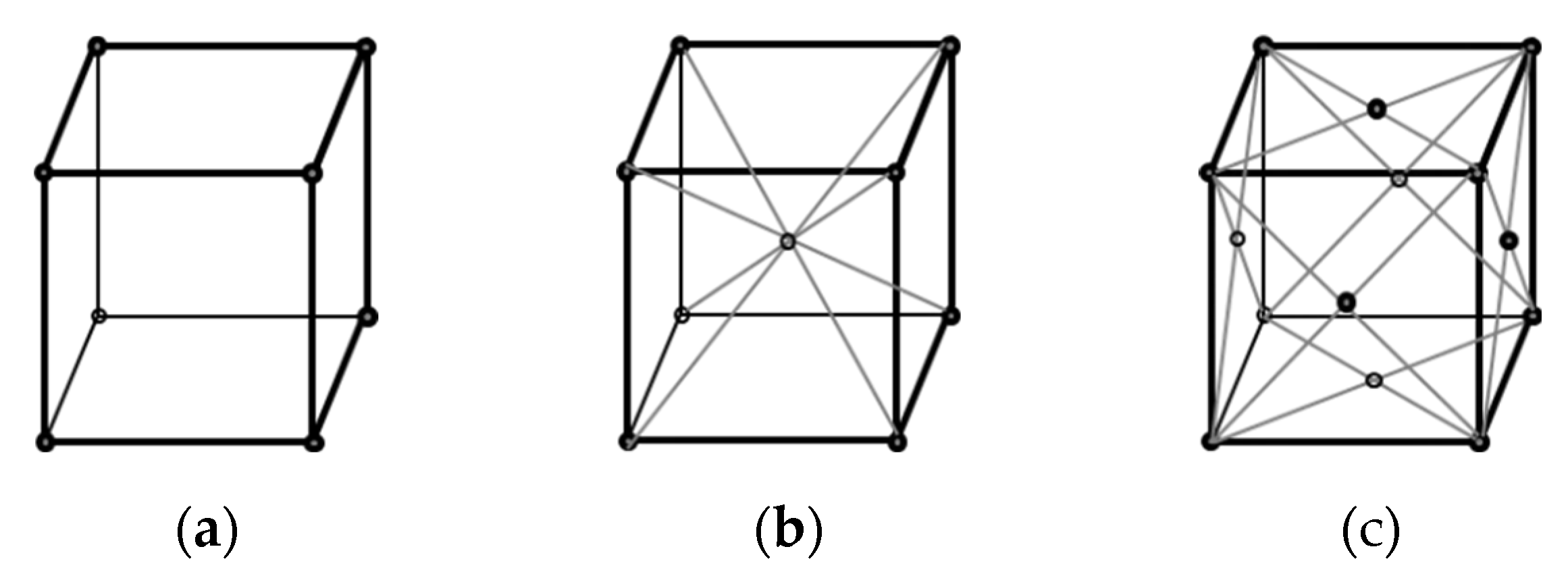
Figure 13.
Multi-layered cube and one layer (square grid). Adapted from [103] with permission.
Figure 13.
Multi-layered cube and one layer (square grid). Adapted from [103] with permission.
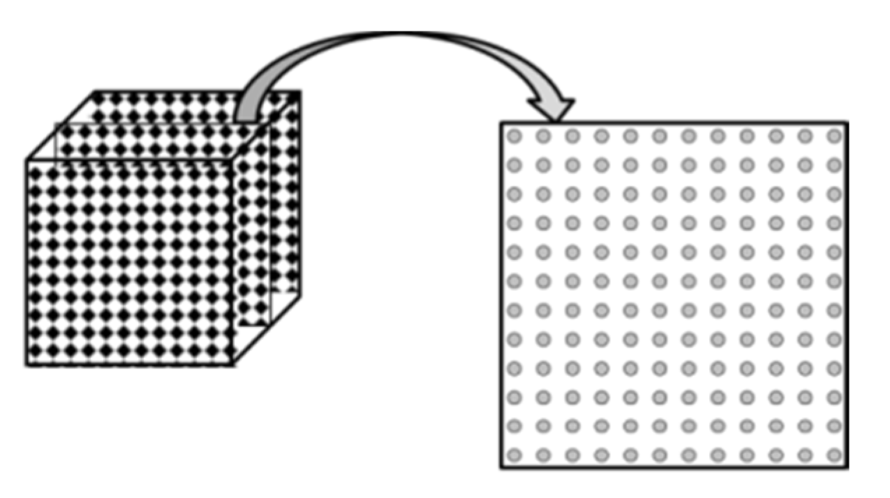
Figure 14.
Three virtual cameras (indicated by arrow): (a) frontal camera, (b) edge camera, and (c) vertex camera. The Miller indices [113] of the crystallographic planes are shown. The face, edge, and vertex closest to the camera are highlighted. Reproduced from [108] under the terms and conditions of the Creative Commons Attribution (CC BY) license.
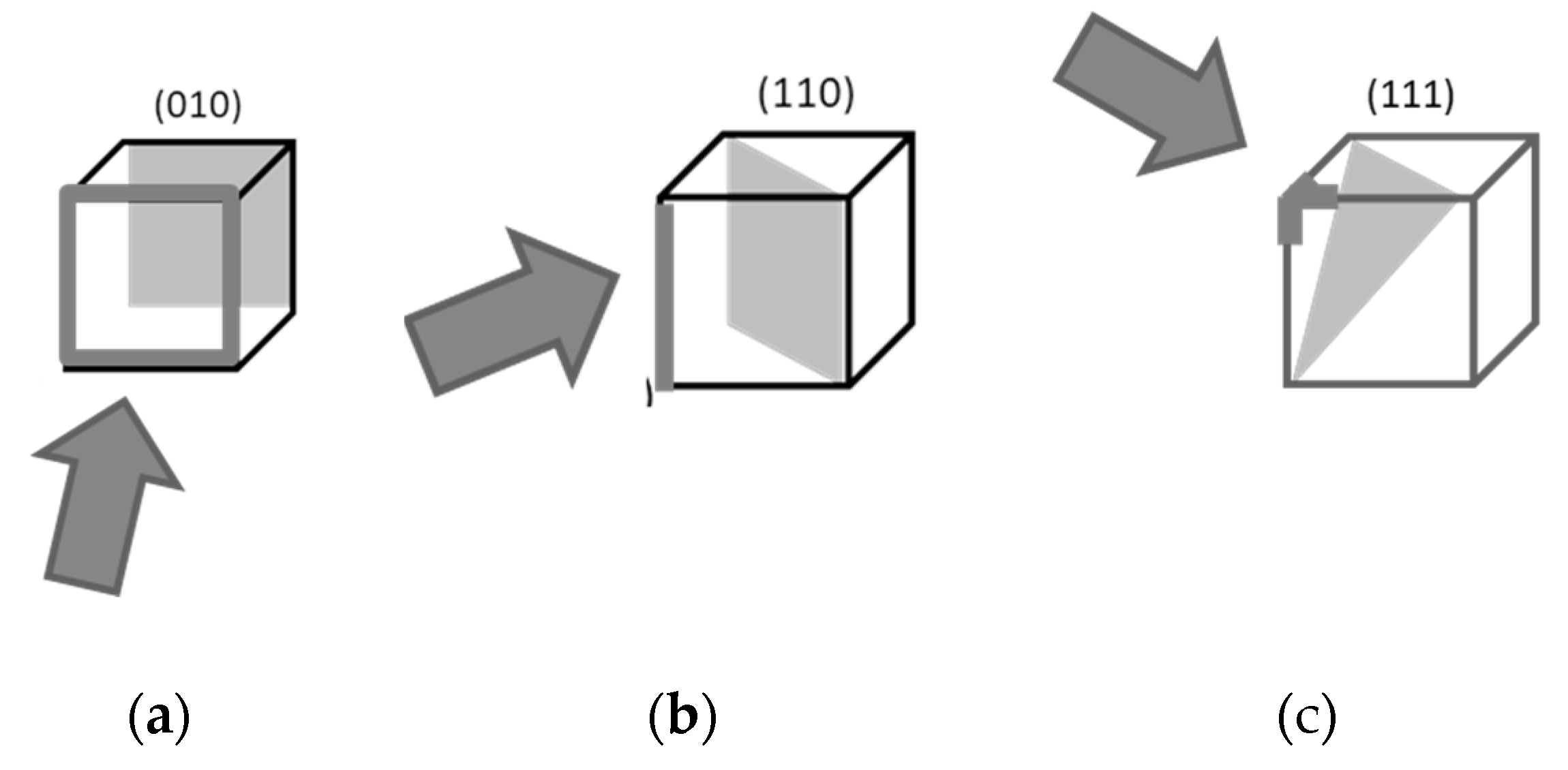
Figure 15.
Frontal camera, multi-layered cube, and one layer (square grid). Reproduced from [103] with permission.
Figure 15.
Frontal camera, multi-layered cube, and one layer (square grid). Reproduced from [103] with permission.
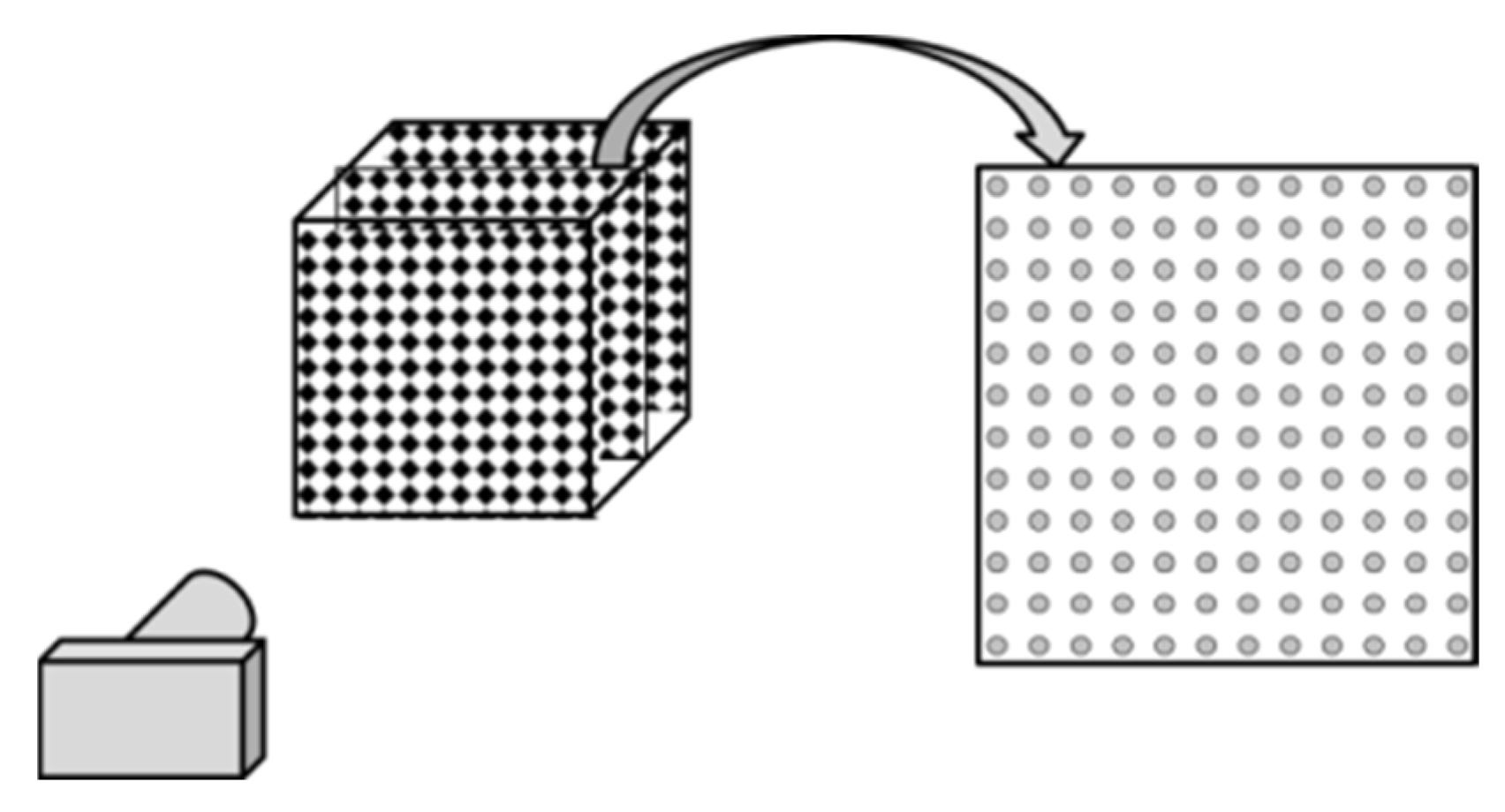
Figure 16.
Moiré patterns of the front camera in simple, body-, and face-centered cubic lattices. Distinctive angles of main corridors and their tangents: 45⁰, 26.6⁰, 18.4⁰; 1/1, ½, 1/3. Adapted from [108] under the terms and conditions of the Creative Commons Attribution (CC BY) license.
Figure 16.
Moiré patterns of the front camera in simple, body-, and face-centered cubic lattices. Distinctive angles of main corridors and their tangents: 45⁰, 26.6⁰, 18.4⁰; 1/1, ½, 1/3. Adapted from [108] under the terms and conditions of the Creative Commons Attribution (CC BY) license.
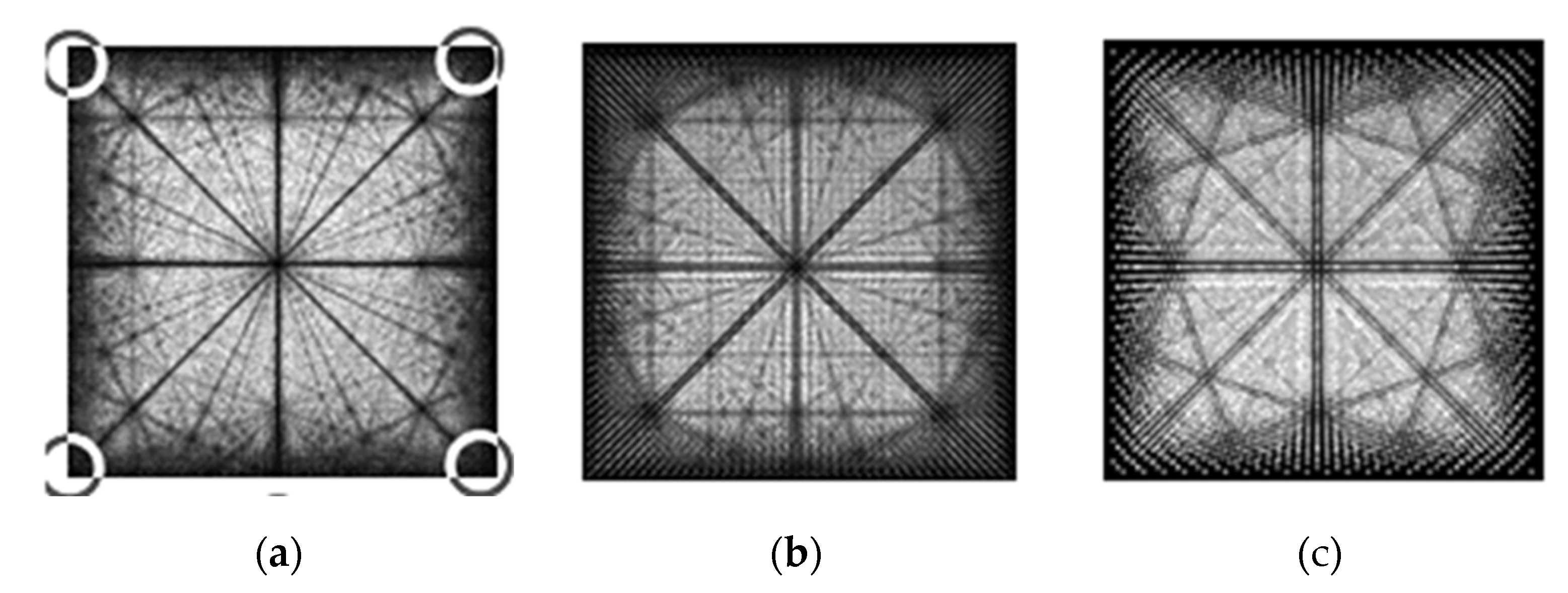
Figure 17.
Main moiré corridors in the cube. Reproduced from [108] under the terms and conditions of the Creative Commons Attribution (CC BY) license.
Figure 17.
Main moiré corridors in the cube. Reproduced from [108] under the terms and conditions of the Creative Commons Attribution (CC BY) license.
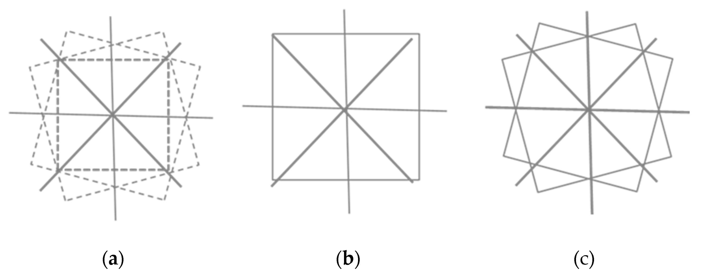
Figure 18.
How moiré corridors appear.
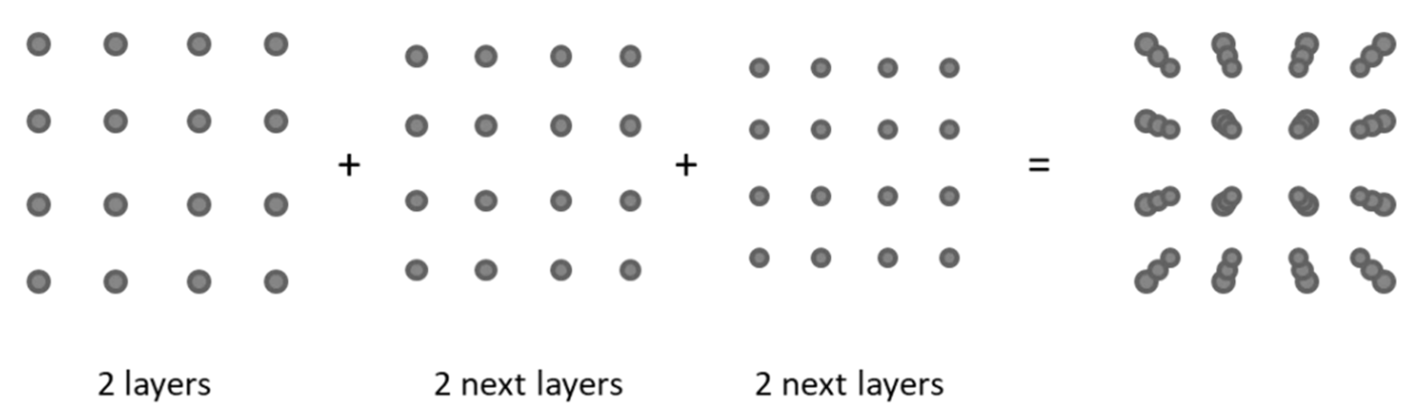
Figure 19.
Fourier transform of image of frontal camera. Reproduced from [103] with permission.
Figure 19.
Fourier transform of image of frontal camera. Reproduced from [103] with permission.
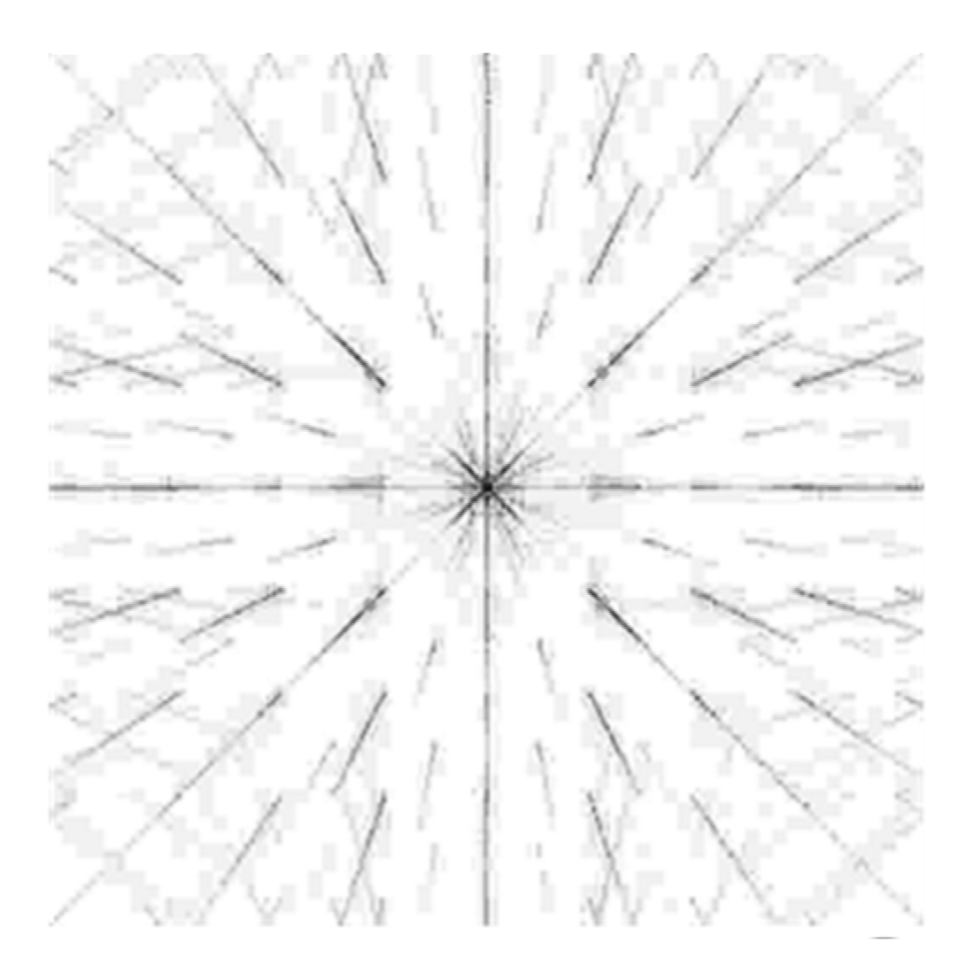
Figure 20.
Voxels and layers of the edge camera. (Schematic, not a projection.) One layer (camera view) is shown in (a), top view in (b). Adapted from [103] with permission.
Figure 20.
Voxels and layers of the edge camera. (Schematic, not a projection.) One layer (camera view) is shown in (a), top view in (b). Adapted from [103] with permission.
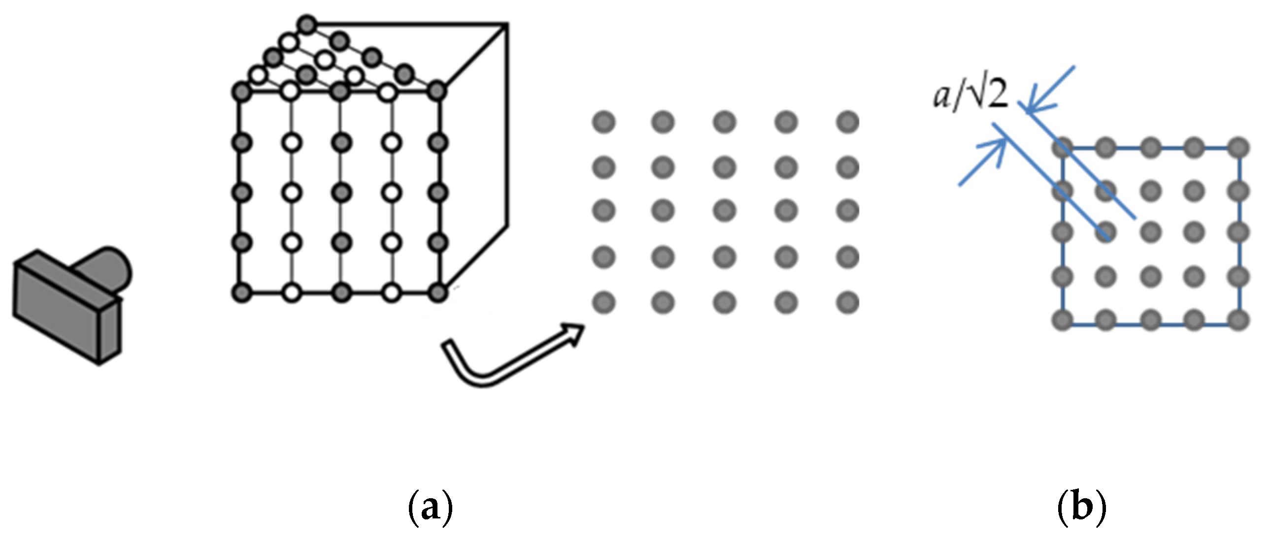
Figure 21.
Two visually merged successive layers (scheme).
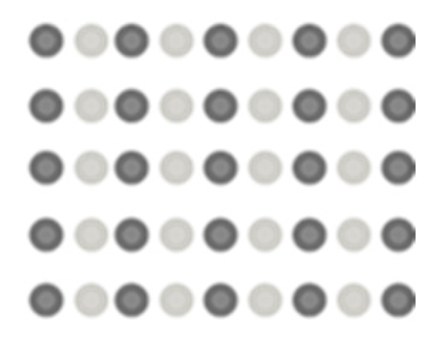
Figure 22.
Moiré patterns of the camera opposite the edge for the three types of cubic lattices, as in Figure 16. Distinctive angles and their tangents: 35.3⁰, 25.2⁰, 19.5⁰; √2/2, √2/3, √2/4. Adapted from [108] under the terms and conditions of the Creative Commons Attribution (CC BY) license.
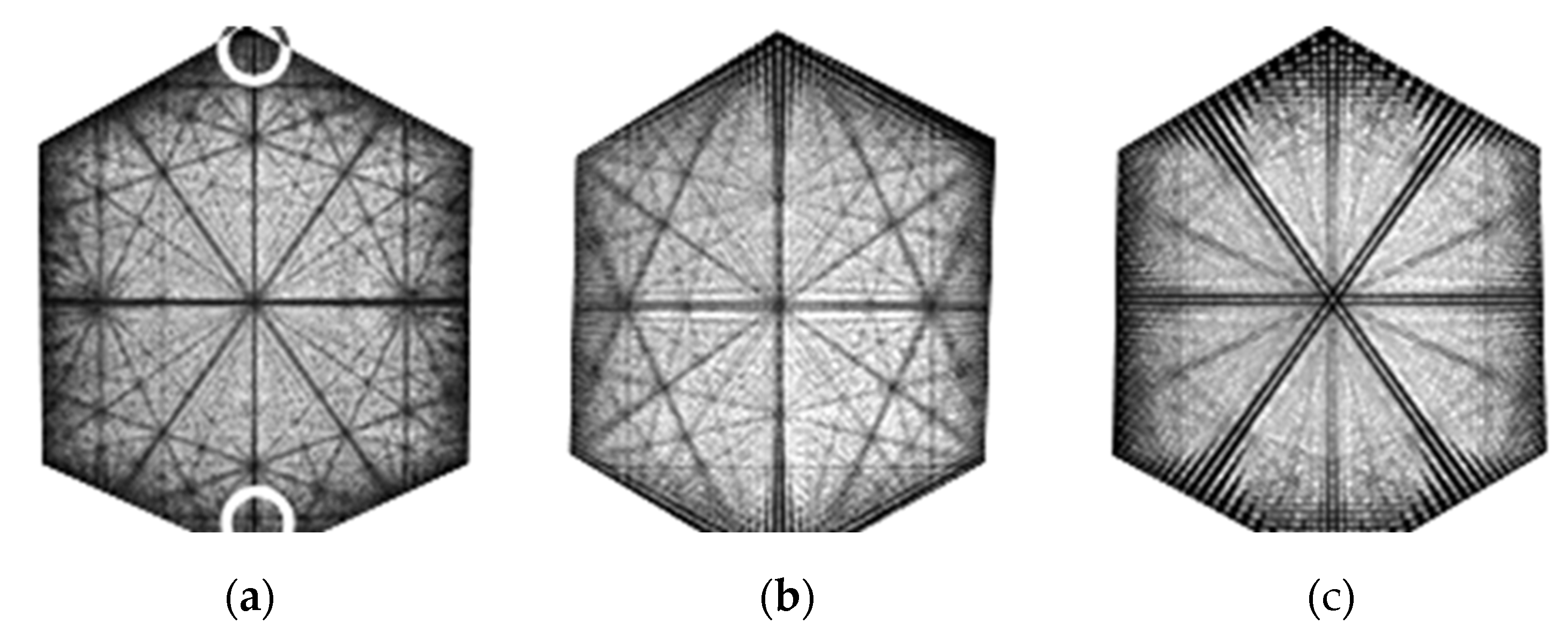
Figure 24.
Voxels and layers of vertex camera. (b) Visual picture of a triplet consisting of three successive layers (from 6th to 9th). Several elemental triangles show the structure. Adapted from [103] with permission.
Figure 24.
Voxels and layers of vertex camera. (b) Visual picture of a triplet consisting of three successive layers (from 6th to 9th). Several elemental triangles show the structure. Adapted from [103] with permission.
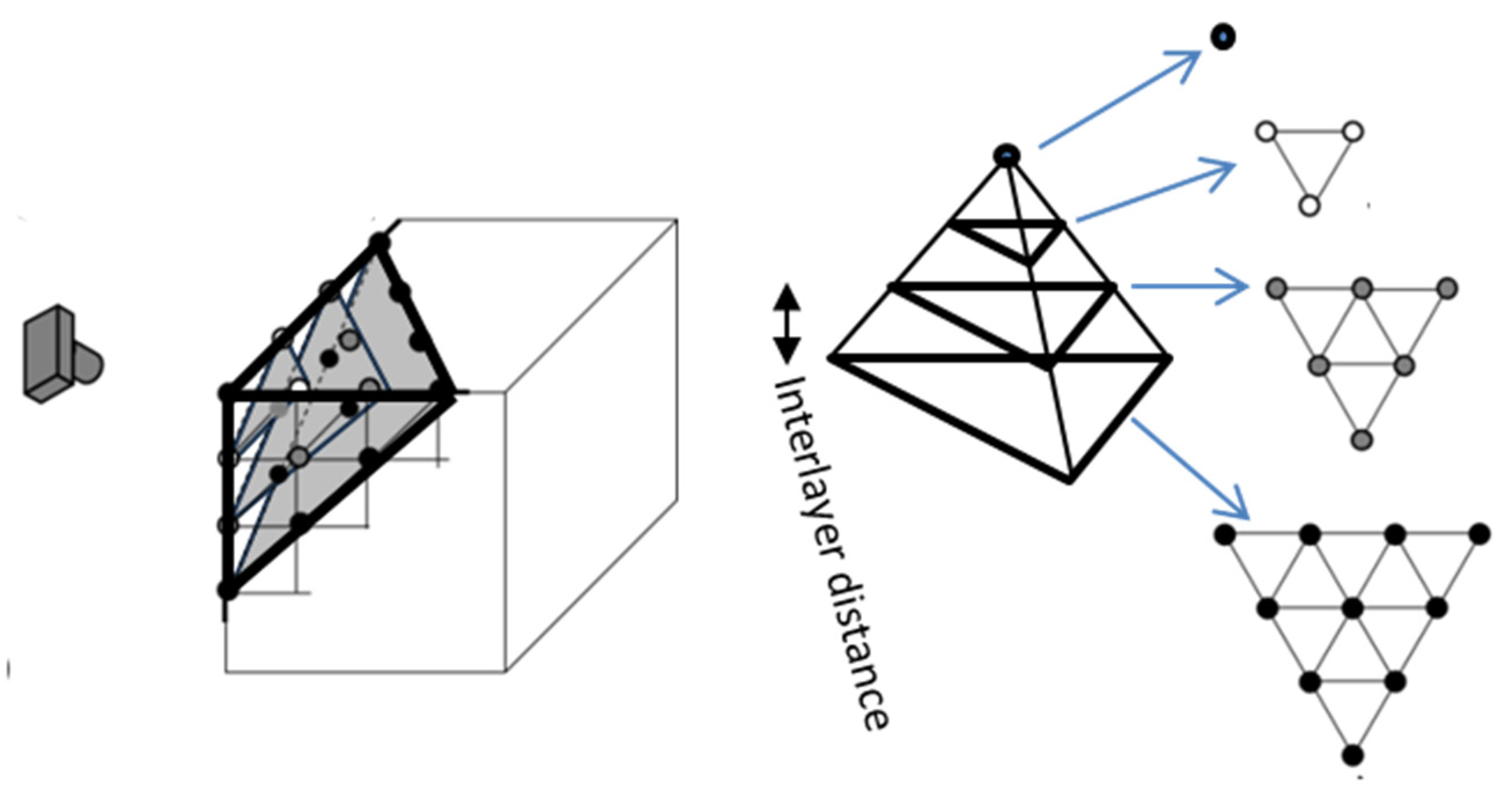
Figure 25.
Scheme of three successive layers: layers 1-3, layers 6-8. Adapted from [103] with permission.
Figure 25.
Scheme of three successive layers: layers 1-3, layers 6-8. Adapted from [103] with permission.
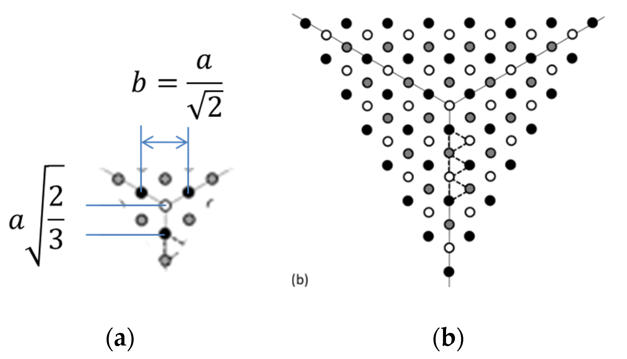
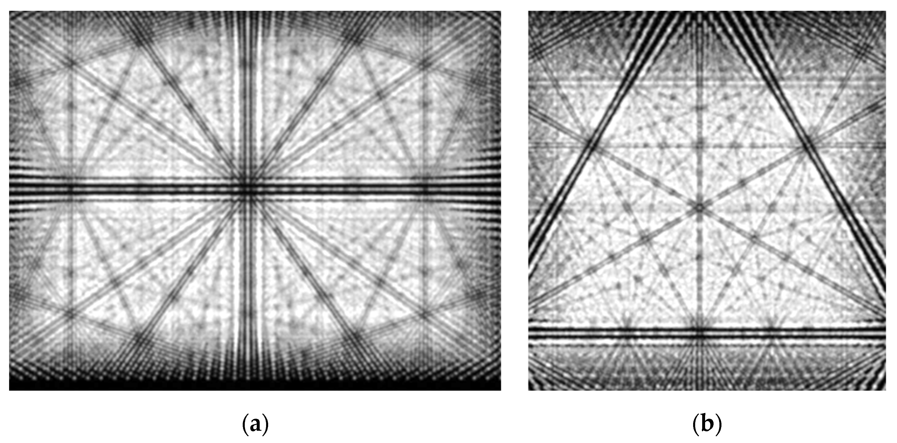
Figure 26.
Moiré corridors of the camera opposite the vertex for three types of cubic lattices, as in Figure 16. Distinctive angles:30⁰, 19.1⁰, 13.9⁰; √3/3, √3/5, √3/7. Adapted from [108] under the terms and conditions of the Creative Commons Attribution (CC BY) license.

Figure 28.
Moiré corridors of the two cameras obtained in the alternative layer layouts.
Disclaimer/Publisher’s Note: The statements, opinions and data contained in all publications are solely those of the individual author(s) and contributor(s) and not of MDPI and/or the editor(s). MDPI and/or the editor(s) disclaim responsibility for any injury to people or property resulting from any ideas, methods, instructions or products referred to in the content. |
© 2025 by the authors. Licensee MDPI, Basel, Switzerland. This article is an open access article distributed under the terms and conditions of the Creative Commons Attribution (CC BY) license (http://creativecommons.org/licenses/by/4.0/).
Copyright: This open access article is published under a Creative Commons CC BY 4.0 license, which permit the free download, distribution, and reuse, provided that the author and preprint are cited in any reuse.


