Submitted:
02 December 2025
Posted:
02 December 2025
You are already at the latest version
Abstract
This work investigates the application of generative design in the development of gear wheels, with emphasis on the relationship between geometry, manufacturing technology, and material selection. Material properties such as strength, stiffness, fatigue resistance, and manufacturability significantly influence both the achievable level of shape optimization and the resulting weight reduction. Generative design enables the adaptation of gear-body geometry to the mechanical characteristics of individual material classes, supporting efficient material utilization while ensuring the required stiffness. The study evaluates the effects of various manufacturing technologies—additive manufacturing, subtractive machining, and casting—by considering material processability and structural constraints. The results demonstrate that the combination of material and manufacturing method substantially shapes the design space: additive manufacturing allows lightweight and organic structures with high geometric freedom; milling requires tool-accessible geometries; and casting benefits from local reinforcement in the area around lightening holes, improving stiffness and stability. The analyses confirm that material selection is a decisive factor in the effectiveness of generative gear design, as an appropriate choice contributes to an improved balance between weight, stiffness, and production cost. The presented framework integrates shape optimization, load evaluation, and material constraints to support the development of innovative, efficient, and manufacturable gear geometries for modern engineering applications.
Keywords:
production technologies
; material design
; spur gear
; generative design
1. Introduction
The continuous advancement of digital design and manufacturing technologies is fundamentally transforming the paradigms of modern mechanical engineering. Traditional computer-aided design (CAD) systems, which have been developed for decades with respect to conventional manufacturing processes, are now reaching their limits due to the rapid evolution of additive manufacturing (AM) capabilities [1]. In response, new computational methodologies such as topology optimization (TO) and generative design (GD) have emerged, providing engineers with unprecedented flexibility in creating complex geometries that meet requirements for mechanical performance, manufacturability, and efficient material utilization. In contrast to the traditional top-down approach driven by the designer, GD introduces a simulation-based, iterative methodology in which algorithms explore the design space within defined boundary conditions and propose optimal configurations [2].
Generative design and topology optimization tools are increasingly being adopted in industrial applications as integral components of simulation-driven product development processes. Their integration with additive manufacturing enables the creation of lightweight structures with improved stiffness-to-weight ratios and reduced material consumption while maintaining structural integrity [3,4]. Studies have demonstrated that GD allows the redesign of components already in the early stages of development, leading to significant reductions in both weight and production time compared to conventional optimization strategies [1,5]. This shift toward algorithmic and AI-assisted design highlights the evolving role of the engineer—from a manual shape creator to a definer of objectives, constraints, and performance criteria within computational frameworks [2,6].
Recent research demonstrates that the integration of GD and TO can yield highly efficient structural solutions across various engineering domains—from aerospace brackets [7] and robotic components [4], to wind turbine generators [3] and automotive systems [8]. Machine learning and deep learning methods further extend the capabilities of GD by enabling the development of design frameworks that learn from data and generate manufacturable solutions optimized for specific objectives such as stress, weight, and stiffness [9,10]. Reinforcement learning techniques are also being applied to generative processes, allowing the exploration of diverse topological configurations while significantly reducing computational time.
The ability of generative design to integrate manufacturing constraints directly into the design process enables engineers to account for additive manufacturing limitations—such as build orientation, overhangs, and surface quality—already in the early stages of development [11]. Bio-inspired frameworks derived from nature are being explored through topology optimization for their exceptional mechanical properties in 3D-printed components [12].
The convergence of artificial intelligence (AI), machine learning (ML), and generative algorithms has also introduced data-driven and adaptive design strategies capable of learning from previous solutions, thereby significantly accelerating the conceptual design phase and enabling the generation and evaluation of thousands of 3D designs within integrated digital environments [13].
The growing adoption of additive manufacturing technologies complements these advancements by enabling the physical realization of geometrically complex and performance-optimized designs. AM supports rapid prototyping, small-batch production, and the fabrication of metallic and polymer components that were previously unachievable using traditional manufacturing methods. Furthermore, the development of hybrid technologies combining additive and conventional casting techniques opens new possibilities for producing optimized parts with enhanced material utilization and mechanical performance [14]. These approaches are particularly relevant for components such as gears and transmission elements, where performance, weight, and reliability are critical [15].
In the paper [16], the authors focus on applying topology optimization techniques to the design of gear wheels in order to improve their structural efficiency. The study investigates methods for reducing weight while maintaining strength and reliability under operational loads. Using numerical simulations and computational modeling, the paper demonstrates how optimized material distribution can enhance performance and extend gear service life. In paper [17], the authors apply generative design to optimize spur gear geometry, reducing material use and weight while maintaining strength and durability. Finite element analysis confirms that this approach yields lighter and more efficient designs for modern engineering applications. In article [18], the authors adapt a force-flow-based topology optimization method to improve generative design processes. Numerical experiments on 2D cases confirm that integrating load-path analysis with generative design produces efficient and manufacturable geometries.
In parallel with advancements in manufacturing, research on material selection plays a crucial role in the success of generative approaches. The choice of material affects manufacturability, mechanical performance, and overall cost. Studies focusing on carbon fiber–reinforced polymers, metallic alloys, and composite filaments have shown that combining material optimization with generative design leads to significant improvements in strength, stiffness, and sustainability, while substantially reducing material consumption and production time. In the context of gear design, understanding the interaction between tool material, cutting parameters, and heat treatment remains essential for achieving long tool life and consistent gear quality [19]. Integrating this manufacturing knowledge into generative frameworks enables the simultaneous optimization of gear geometry, material properties, and process parameters.
Overall, the available literature highlights a clear shift from designer- and experience-driven processes toward automated, data-informed, and optimization-oriented design methodologies. Generative design, in synergy with additive manufacturing and intelligent material selection, provides a foundation for the creation of lightweight, efficient, and manufacturable components. Despite its growing adoption, gaps remain in adapting GD methodologies for highly stressed mechanical components, such as gears, where precise engagement geometry, surface integrity, and material properties are critical for operational reliability.
Therefore, this work focuses on the application of generative design for shaping, selecting manufacturing technologies, and choosing suitable materials for gears. By integrating topology optimization, simulation-based evaluation, and manufacturing constraints, the study aims to provide a comprehensive framework for designing innovative and manufacturable gear geometries that optimize weight, performance, and cost.
2. Materials and Methods
The main objective of this paper is to demonstrate application of generative design in the development of a gear wheel, considering the shape optimization, selection of an appropriate material, and the choice of a suitable manufacturing technology. The research procedure was designed as a multi-stage process consisting of the following steps:
- Definition of input parameters and functional requirements;
- Application of generative design in development of the spur gear;
- Material selection for gear wheels;
- Analysis and simulation;
- Comparison and selection of optimal solution.
2.1. Input Parameters and Geometric Characteristics of Gear Wheel
The first step in the design process of a spur gear was selection of geometric parameters that enable its manufacture using various production technologies—such as machining, forging, casting, or additive manufacturing, specifically the 3D printing.
Within this selection, it was necessary to consider not only the technological limitations of the individual manufacturing methods but also the mechanical requirements of the component itself. A key criterion was the aim of maximizing material savings, primarily for reasons of production efficiency, weight constraints, and environmental aspects. However, at the same time, the required stiffness of gear wheel had to be maintained, as it directly affects the operational reliability and service life of the machine part.
The geometry of the gear wheel—including such parameters as the module, number of teeth, width of toothed rim, profile correction, and hub shape—was therefore designed to achieve a compromise between the manufacturability and the functional requirements.
For the purposes of this study, the presented analysis was carried out for a spur gear with the number of teeth z = 71, standardized module m = 2.5 mm, pressure angle α = 20°, tooth width b = 50 mm, if the size of connection hole is d₀ = 55 mm.
Since suitability of the proposed gear body shape is evaluated according to the tooth stiffness, which is assessed through deformation analysis using the Finite Element Method (FEM), the value of load acting on the tooth side wall was set to a unit value of F = 1000 N.
2.2. Application of Generative Design in Proposal of Spur Gear
This part of the article presents the design process of a spur gear using generative design. The aim is to explore the possibilities of optimizing the gear body shape in terms of weight, stiffness, and material efficiency, while simultaneously considering the technological constraints of various manufacturing methods.
At present, several software tools are available on the market that support the principles of generative design. Among the most well-known are, for example:
- Autodesk Fusion 360 – enables a comprehensive CAD/CAM solution that integrates generative design directly into the design environment and allows the definition of technological, functional, and geometrical constraints. It is popular for its intuitive interface and broad accessibility.
- Siemens NX (Generative Design) – is an advanced tool primarily used in industrial applications, offering a high level of control over the design process and strong integration with other CAE modules.
- PTC Creo (Generative Topology Optimization) – provides shape optimization with an emphasis on integration into the design process and linkage with FEM analysis.
- SolidWorks (3DEXPERIENCE/Topology Optimization) – is widely known in mechanical engineering, it provides topology optimization capabilities and integration with stress analysis.
- Topology – is a modern software focused on advanced shape optimization, suitable for additive manufacturing, offering a high degree of parameterization and computational control.
For the purposes of this study, the Autodesk Fusion 360 was selected, because it provides robust generative-design functionality and allows the specification of manufacturing constraints (e.g., bi-directional machining, additive manufacturing). Considering the focus on the universal manufacturability of the gear wheels using various technologies, this platform was evaluated as the most suitable for the intended application.
This generative study constitutes the fundamental framework within the Autodesk Fusion 360 environment, where all input data related to a specific design problem are defined. It comprises a set of parameters, geometric constraints, loads, manufacturing conditions, and objectives that collectively form a comprehensive description of the design task, based on which the software automatically generates optimized design solutions.
Each generative model may contain multiple individual studies, with each one focusing on different aspects of the design—such as varying load conditions, manufacturing technologies, or material selections. This approach enables efficient comparison of alternatives and facilitates the selection of the most suitable variant in terms of functionality, weight, and manufacturing costs.
The following procedure outlines the main steps required to create a generative study for a spur gear within the Fusion 360 environment:
- Creation of a new generative study and basic project setup;
- Definition of boundary (obstacle) geometry;
- Specification of the design space for the generative proposal;
- Definition of boundary conditions – model constraints;
- Definition of design conditions – loads;
- Definition of design criteria in terms of manufacturing and functionality;
- Selection and definition of materials in generative design.
2.2.1. Creating of New Generative Study and Basic Project Setup
The design process begins with creation of a new generative study within the Generative Design module of Autodesk Fusion 360. In this step, the type of analysis is specified— in this case, a generative design study rather than a conventional static simulation— and a framework is established for the subsequent definition of design conditions, constraints, and optimization objectives.
A key element of this step is creation of the generative model, that is, the input geometry serving as the initial shape of the design. This model includes the definition of regions that must be preserved in the design, as well as those that can be optimized by the software. In the case of a spur gear, this geometry must comply with standardized shape and dimensional requirements specified by relevant technical standards.
In the design process, the fundamental geometric rules for spur gears were observed. For instance, the thickness of the rim below the teeth must be at least 3.5 times the standardized module. This requirement ensures sufficient stiffness and strength in the transition zone between the gear teeth and the wheel body. In addition, the hub height above the bore was defined based on the anticipated method of mounting the gear onto the shaft— for example, by means of keyed connection or press connection. For this reason, a minimum material thickness above the bore was strictly specified to maintain adequate load-carrying capacity during torque transmission.
In this way, a design foundation was established that satisfies both the requirements of generative design and also the functional and structural requirements for a spur gear in accordance with applicable standards.
Figure 1 (a) shows the input geometry of the spur gear, with the regions that must be preserved during optimization highlighted—such as the material above the mounting hole and the part of the rim beneath the teeth. These regions constitute the so-called preserved geometry, which remains unchanged throughout the generative design process, thereby ensuring compliance with the functional requirements and assembly conditions.
2.2.2. Defining of Bounding (Obstacle) Geometry
Within the generative design process, it is important not only to define the regions that can be optimized, but also to precisely specify the space that the design must avoid. In the Fusion 360 environment, this type of geometry is referred to as obstacle geometry—that is, the obstacle or restricted geometry.
These regions represent areas, into which the new design must not intrude, for various reasons—such as assembly constraints, the motion of other components within the assembly, tool accessibility requirements, or the need to maintain functional tolerances. During the generation of design variants, the software strictly treats these volumes as non-penetrable.
In the case of the spur gear, the obstacle geometry was defined, for example, as the inner region around the shaft bore, where no intrusion into the minimum wall thickness of the designated hub is permitted. Similarly, areas near the gear rim were marked as restricted, as they are technologically designated for precise machining or for contact with other components in the assembly.
Figure 1 (b) illustrates an example of the obstacle geometry assignment in the model, which defines the space into which the generated design must not intrude.
2.2.3. Defining of Design Space for Generative Proposal
After defining of the obstacle regions that the generated design must avoid and marking the preserved parts of the model, the next step is to delineate the so-called Design Space. This space represents the volume in which the software is “allowed” to create new geometric forms based on the specified objectives, loads, and manufacturing constraints.
The design space does not represent a specific shape, but rather the potential volume within which the algorithm searches for the optimal form. In Autodesk Fusion 360, this space is derived from the total model volume after subtracting the obstacle and preserved regions. In other words, it represents the “free” space between what must remain unchanged (e.g., assembly features, functional surfaces) and what the design must avoid (e.g., collision zones, technological allowances).
In the design of the spur gear body, the design space primarily encompasses includes the region between the hub and the gear rim—i.e., the area where optimization can generate a lightweight yet sufficiently stiff and strong structure. Within this space, the software can create various topologies (e.g. ribbing, organic transitions) that would be difficult to design manually.
Figure 1 (c) shows the division of the different types of geometry, where the obstacle geometry is indicated in red, and the preserved geometry is indicated in green. The uncoloured portion of the model represents the design space, within which the design will be generated.
2.2.4. Defining of Boundary Conditions – Model Constraints
In this phase of the generative study, it is necessary to specify how the component is supported or mounted in actual operation. This information is essential for the software to correctly evaluate load responses and generate a shape that corresponds to the real-world usage conditions.
In Autodesk Fusion 360, these conditions are defined as the so-called constraints, which involve fixing certain degrees of freedom (e.g., translations, rotations) on specific faces or bodies. Constraints simulate, for example, a rigid attachment to a base, mounting on a shaft, contact with other components in the assembly, or symmetry conditions.\
Figure 2 illustrates the placement of constraints on the input model of the spur gear. In the case of the spur gear, it was necessary to consider that the gear is mounted on a shaft and transmits torque. Therefore, selected areas of the inner bore of the hub, which simulate a rigid mounting—e.g., via a key, groove, or interference fit—were designated as support (fixed) surfaces. The fixation was configured to ensure the model was stably held while still allowing realistic deformations that occur during operation.
2.2.5. Defining of Design Conditions – Loads
After defining the constraints that simulate the clamping or mounting of the component, the next step involves specifying the loads—such as forces, torques, or pressures—to which the model will be subjected during operation. This step is crucial, as it determines how the model is loaded and thus directly influences the selection of the optimal geometry in the generative design process.
In Autodesk Fusion 360, various types of loads can be applied, including pressure, forces—either tensile or compressive—torque, as well as custom load combinations.
Loads enable the software to identify which regions of the model must withstand mechanical stresses and what the expected design strength requirements are. At least one load must be applied to a portion of the geometry that remains preserved in order for the computation to be valid. It is also important to note that a constraint and a load cannot be applied simultaneously to the same face or edge; therefore, their correct distribution is essential.
In the case of a spur gear, there are three fundamental approaches to defining the load acting on the gear teeth.
The first approach involves specifying the maximum force acting on a single tooth (Figure 3). Since the gear wheel consists of 71 teeth, the software processes this situation as 71 separate studies, each simulating the loading of one specific tooth. The force is defined as a continuous load.
The second approach involves applying the total torque acting on the gear (Figure 4). The software then distributes this torque among the teeth according to their number and position in mesh, allowing for a more realistic and comprehensive load simulation
The third and most critical approach assumes that all 71 teeth are simultaneously subjected to the maximum force (Figure 5). This model is the most conservative and is used in cases where it is necessary to evaluate the maximum possible load acting on all teeth at once.
2.2.6. Definition of Design Criteria in Terms of Manufacturing and Functionality
When applying generative design within the Autodesk Fusion 360 environment, it is essential to accurately define the design criteria, representing the objectives and manufacturing constraints required to specify the solver parameters. Based on these objectives, the software produces manufacturable design solutions that satisfy the defined functional and technological requirements.
The design criteria therefore define the framework within which the design process is carried out. The fundamental objectives include the reduction of component weight, optimisation of mechanical performance, minimisation of material consumption, and improvement of structural stiffness. At the same time, manufacturing constraints are considered, such as the selected production technology (additive or subtractive), material availability, manufacturing accuracy, and the economic efficiency of the process.
Within this study, the design is primarily focused on minimising the weight of the gear wheel, contributing to material savings and a reduction in the energy intensity of production, while maintaining optimal tooth stiffness and overall component strength. Generative design in Autodesk Fusion 360 enables the achievement of this balance through algorithmic shape optimisation, whereby the material is distributed only in areas subjected to actual load transmission.
The design criteria defined in this way enable the Autodesk Fusion 360 system to generate design variants that are not only functionally reliable but also efficiently manufacturable, thereby enhancing the quality and cost-effectiveness of the gear wheel design process.
In the design of gear geometry using generative design within the Autodesk Fusion 360 environment, optimisation limits play an important role in defining the boundaries of admissible solutions. These limits represent supplementary requirements that the algorithm must observe during the computation process to ensure that the resulting design meets the functional, strength, and technological criteria. The solver aims to satisfy the specified limits, although achieving them may not always be possible due to the complexity of the geometry and the nature of the model loading.
The main optimisation limits considered in this study include:
- Safety factor – defines the ratio between the material’s yield strength and the maximum von Mises stress within the model. This parameter ensures that the generated design possesses a sufficient strength reserve and that the material’s load-bearing capacity is not exceeded.
- Target mass – specifies the desired mass of the resulting model and enables a balance to be achieved between material savings and the preservation of the required stiffness. In this study, the design is oriented towards reducing the weight of the gear wheel while maintaining tooth stiffness and the overall strength of the component.
- Modal frequency – allows the inclusion of dynamic performance requirements in the computation. By specifying the minimum frequency of the first natural mode, it is ensured that the design will not be susceptible to resonance at the operational rotational speeds of the gear wheel.
- Displacement (deformation) limit – defines the allowable displacement values in specific regions of the model. This parameter is essential for maintaining the geometric accuracy of the gear teeth and ensuring reliable tooth engagement during torque transmission.
The correct definition of these limits is crucial for achieving results that meet the required strength and functional properties while being simultaneously optimised in terms of weight and technological feasibility. In combination with the design objectives, the limits therefore represent a fundamental tool for controlling the quality and efficiency of the resulting generative model of the gear wheel.
Within the Autodesk Fusion 360 environment, the command Manufacturing Constraints allows the definition of manufacturing limitations that the generative design must respect. These constraints represent an important part of the optimisation process, as they ensure that the generated shapes are not only functionally and structurally suitable but also practically manufacturable using the selected production technology.
For each selected manufacturing method, the system generates a separate set of results demonstrating how the design has been optimised with respect to specific technological requirements. This enables the comparison of individual design variants and the analysis of trade-offs between performance, weight, aesthetics, and technological feasibility.
The most commonly used manufacturing methods in generative design include:
- Additive manufacturing (3D-printing) – allows the creation of complex and organic shapes that would be impossible to produce using conventional methods. It is particularly suitable for prototypes or lightweight structures with an emphasis on saving material.
- Subtractive manufacturing (machining) – includes processes such as milling or turning. Within generative design, it is possible to define the machining direction, tool access axes, and geometric constraints to ensure that the resulting shape is suitable for this type of manufacturing.
- Casting or forging – is mainly used in mass production, where emphasis is placed on repeatability, surface quality, and dimensional accuracy. Generative design can assist in optimising the shape of the casting or forging to reduce weight while maintaining strength.
In the context of this study, the analysis focuses primarily on comparing the suitability of additive and subtractive manufacturing technologies in the design of the gear wheel. The objective is to identify which of the methods enables a more efficient realisation of the generated geometry in terms of weight, stiffness, and manufacturing accuracy.
2.2.7. Selection and Definition of Materials in Generative Design
Material selection is a key factor in the generative design of gear wheels, as the physical properties of the material significantly influence the resulting geometry and the mechanical characteristics of the component. Correct material definition within the Autodesk Fusion 360 environment enables the solver to generate designs that meet the requirements for strength, stiffness, and weight.
During the generative design process, the following material properties are of primary importance:
- Yield strength – is used to calculate the safety factor, ensuring that the design does not exceed the material’s load-bearing capacity and remains resistant to operational loads.
- Young’s modulus and Poisson’s ratio – these mechanical characteristics are crucial in solving linear stress and deformation problems, enabling the generation of geometries that optimally combine stiffness and weight.
- Material density – is used in calculating the model’s weight as well as in simulations of gravitational loading or dynamic behaviour. The material density must be defined correctly to ensure that the physical simulations accurately influence the resulting geometry of the gear wheel.
The correct definition of the material is an integral part of the entire generative design process, as the material properties, together with the design criteria and manufacturing constraints, determine the final geometry, functionality, and manufacturability of the gear wheel.
2.3. Material Selection for Gear Wheels
In generating the gear wheel design proposals, several material alternatives were considered. The selection of a specific material was based not only on technical parameters (strength, hardness, wear resistance) but also on the technological and economic factors (cost, availability, machinability, and suitability for additive manufacturing).
An important factor in the selection of material was the chosen manufacturing technology of the gear wheel. For the individual manufacturing methods, the following alternatives were considered:
- Additive manufacturing (3D-printing)
This method enabled the realization of complex shapes with optimized geometry that would not be feasible to manufacture using conventional processes. From a material standpoint, polymer and composite materials suitable for 3D printing were therefore considered, such as:
- PA12 GF30 (Nylon with 30% glass fiber reinforcement);
- CarbonX PA-CF (Nylon reinforced with carbon fibers);
- Zytel® PA-CF by DuPont (carbon fiber–reinforced nylon.
These filaments combine low weight with sufficient strength, stiffness, and wear resistance, making them suitable for functional prototypes and lightweight gears subjected to lower loads. For applications requiring higher dimensional stability and reduced friction, POM (polyoxymethylene, also known as Acetal or Delrin) was also used, as it exhibits excellent tribological properties.
- 2.
- Machining (3-axis and 5-axis milling)
In machining, the selection was based on the availability of materials suitable for precise mechanical processing. For this manufacturing method, metals were chosen that allow for high dimensional accuracy, good machinability, and adequate mechanical strength:
- Carbon steel S45C (equivalent to C45) – suitable for highly loaded gears requiring high strength and toughness after heat treatment;
- Stainless steel SUS420J2 – appropriate for environments demanding resistance to corrosion and wear, such as applications involving contact with water or humidity;
- Alloy steel SCr415 – a material intended for case hardening, suitable for gears requiring a hard surface combined with a tough core;
- Aluminum alloy EN AW-7075 – used for lightweight gears where low weight is prioritized while maintaining high strength.
The choice between 3-axis and 5-axis machining made it possible to optimize the geometric complexity and minimize the amount of removed material, while maintaining the stiffness and accuracy of the tooth profile.
- 3.
- Casting
In casting, the emphasis was placed on mass production and the geometric complexity of the component. In the case that this manufacturing method was selected, suitable alternatives considered included low-carbon or alloy steels (e.g., S45C, SCr415) and aluminum alloys such as EN AW-7075, which provide a good balance of strength, stiffness, and cost-effectiveness for larger production series.
The material selection defined in this way ensured that each generated gear design was optimized in terms of manufacturing technology, functionality, and efficient material utilization. The chosen combination of materials – ranging from metallic to composite and polymer-based – made it possible to tailor the design to specific requirements for strength, weight, durability, and manufacturing complexity.
3. Results
The geometries of spur gear bodies can vary considerably and often include features such as webs of different shapes, lightening holes, and other structural details. These elements are designed to achieve an optimal combination of weight reduction, structural stability, and manufacturing feasibility, while maintaining the functionality and operational reliability of the gear wheel.
3.1. Generation of Gear Wheel Body Geometry with Definition of Basic Geometrical Constraints
At the beginning of the investigation into the use of Autodesk Fusion 360 for designing the body of a spur gear, freedom was given to the software itself to propose an optimal solution through the principles of generative design. The aim of this approach was to verify the capability of the program to automatically generate shapes that take into consideration the selected manufacturing method, material, and the required functional properties of the component.
The definition of the design space in this case is illustrated in Figure 2. The uncoloured part of the model represents the design space itself, within which the generative design process takes place. A selection of results – that is, the generated solutions for the individual types of manufacturing technologies under torque loading of the gear wheel (Figure 4) – is presented in Table 1.
After completing the computational process, the program generated several alternative design solutions. Table 1 presents only a selected sample of the proposed options. As shown in the presented results, the suitability of several automatically generated solutions does not always correspond to the selected manufacturing methods – certain geometries are atypical and, from a practical manufacturing standpoint, often infeasible. For this reason, the subsequent stage of the analysis involved a more precise definition of the available design space, with the aim of obtaining more realistic and technologically feasible shape proposals.
3.2. Design Optimization Using Refinement of Geometric Constraints
In the design of a spur gear body, the primary objective is to achieve the lowest possible component weight while maintaining the required stiffness and tooth strength. In engineering practice, various structural modifications of gear bodies are therefore commonly applied to enable effective weight reduction without negatively affecting the functional performance of the gear. Among the most frequently used solutions are webs, cutouts, and lightening holes of different shapes, which ensure optimal material distribution. Typical examples of these design configurations are illustrated in Figure 6.
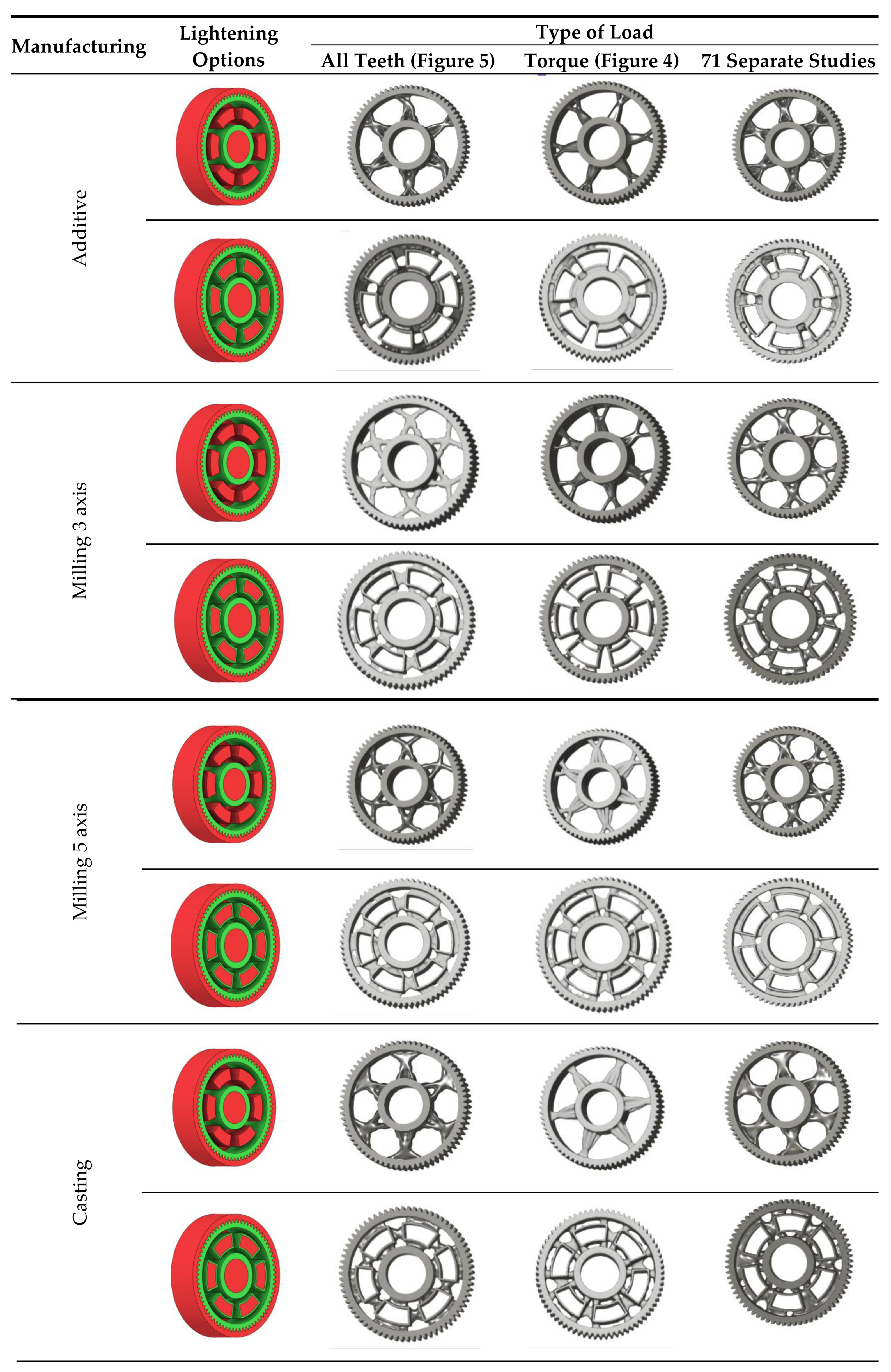
There are several approaches to reduce the weight of a spur gear body. In this study, two specific methods were selected: weight reduction by means of 10 circular holes (Figure 7 – a) and b)) and weight reduction by means of 6 holes (Figure 7– c) and d)). For both types of designs, it is possible to define a material layer of a certain thickness around the holes that must be preserved. Such a constraint modifies the design space and simultaneously influences the final geometry of the gear body generated by the software.
As previously mentioned, the red volumes represent regions into which the generated geometry must not extend, whereas the green volumes denote the areas of material that must be preserved. The design space corresponds to the free volume within the model where the generative algorithm is allowed to create the new shape of the gear body.
Table 2 presents selected solutions for the generated shapes of spur gear bodies with circular lightening holes. For the individual variants, different manufacturing approaches are considered, comparing options with preserved material around the lightening holes and those without such preservation.
3.3. Design Optimization Using Gear-Tooth Stiffness and Volume of Body Wheel Minimization
In this case, it was possible to monitor the change in the mass or volume of the gear wheel as the primary optimization criterion. Since the study also considered the influence of the manufacturing method, various materials with different densities and mechanical properties were proposed, which resulted in different volumes and masses of the final designs. Therefore, the study focused on volume as the priority parameter over mass, allowing the assessment of design efficiency independently of the selected material. Based on the calculated volume of each variant, this parameter was compared with the volume of a solid (unrelieved) gear body (Figure 8), providing a unified measure of material savings. Such a comparison makes it possible to quantify the degree of structural light-weighting and to identify the most efficient geometries in terms of volume of wheel body.
The results indicate which regions of the gear can be lightweighted without compromising stiffness or strength, and which areas require material retention to preserve the functional characteristics. This approach provides a practical tool for decision-making regarding material selection and manufacturing technology, as a reduced volume enables a broader choice of cheaper or lighter materials. The volume value relative to the solid gear body thus becomes a key criterion in gear-shape optimization, providing a clear metric for comparing different design variants.
During gear meshing, tooth deformations occur as a result of the transmission force acting between the tooth flanks. These deformations affect motion-transfer accuracy, transmission noise, and load distribution within the mesh. Gear mesh stiffness represents the resistance of the teeth to these deformations and defines the relationship between the applied force and the resulting deflection or displacement in the mesh.
The mesh stiffness of a gear pair is not constant—it varies throughout the meshing cycle as the contact point shifts along the tooth flanks and the number of simultaneously engaged tooth pairs changes. Determining the overall mesh stiffness is therefore a complex task that involves bending, shear, contact, and torsional deformations of the teeth, as well as the elastic effects of shafts and bearings.
To simplify the problem, the analysis often starts with evaluating the stiffness of an individual tooth subjected to a force applied at a specific point, most commonly at the tooth tip. This approach makes it possible to examine the tooth’s behavior under a known load and to derive its bending and contact stiffness. Tooth stiffness can be characterized as the ratio of the applied force to the corresponding deformation, typically in the direction normal to the line of action.
In this case, tooth stiffness was determined based on the deformation induced by a load applied at the tooth tip. It was assumed that the force acts in the direction normal to the tooth flank at the contact location, which best represents the real conditions in gear meshing (Figure 9). To determine the resulting deformation, the finite element method (FEM) was employed, allowing detailed evaluation of the stress–strain state within the individual regions of the tooth. The tooth model was loaded with a unit force of F = 1000N, and the stiffness was subsequently calculated as the ratio between the applied force and the corresponding deformation.
The deformation along the entire tooth width is neither uniform nor constant. The deflection values of the gearing vary depending on whether the loaded tooth is located directly above the lightening segment of the gear wheel body or outside its influence. When the tooth is positioned above this lightened segment, its stiffness is reduced, resulting in greater deformation compared to a tooth situated in a fully supported section of the gear wheel body. This difference is clearly visible in Figure 10, which illustrates the increased tooth deflection above the lightening segment. For this reason, the analysis was conducted considering the most unfavorable loading condition, specifically when the applied force acts on a tooth positioned above the lightening segment. This configuration represents a less stiff support for the tooth, resulting in higher deformation values and allowing the evaluation of the gear wheel under the most critical operational conditions.
Figure 11 presents the results of the analysis of the gear body shape design for models with circular lightening holes, evaluated with respect to different manufacturing methods. From the set of proposed solutions for each manufacturing technology, representative variants were selected. For these variants, the gear body volume was examined and compared to the solid (full) gear body, whose volume is considered as 100%. Additionally, the tooth deformation and stiffness above the lightening hole were analyzed and compared to the deformation and stiffness of the teeth in the solid gear body. Based on this case study, it can be concluded that when using generative design for selecting the shape of a gear body, the most appropriate loading method is to apply the force simultaneously to all teeth. Alternatively, a series of individual studies for each tooth can be used. Furthermore, it is preferable to use a lightening-hole variant without preserving material around the holes.
The analysis for lightening holes of shapes other than circular is shown in Figure 12. This study also confirms the most appropriate loading method, similar to the previous case, and likewise supports the use of a lightening concept without additional material around the lightening holes. The differences in volume among the selected representative models are comparable; more significant differences occur in tooth deformation and stiffness, which depend on the influence of the body geometry and the chosen manufacturing method.
In the design of gears, it is often desirable to minimize the volume of the gear body, resulting in material savings and a reduction in the overall weight of the transmission system. However, the reduction of volume must be achieved while maintaining the required tooth stiffness and strength so that neither service life nor operational performance is compromised [20]. Geometry optimization—such as adjusting the disk thickness, hub shape, or removing material from less-loaded regions—makes it possible to achieve an effective balance between weight reduction and mechanical resistance. Therefore, the design process relies on stiffness and stress analysis results, which identify critical areas where material can be removed without affecting functionality. Such an approach leads to a more efficient, lighter, and cost-effective gear design, suitable even for modern dynamic applications.
4. Conclusions
The selection of an appropriate material represents a key factor in the design of gear wheels, particularly in combination with generative design methods. Material properties—such as strength, toughness, elastic modulus, fatigue resistance, and manufacturability—significantly influence the final geometry of the optimized gear body as well as the achievable weight reduction.
Generative design enables the development of geometrical solutions precisely tailored to the mechanical characteristics of the chosen material. High-strength and stiffer materials allow for greater volume reduction, whereas lower-strength materials require more robust constructions or additional reinforcement in critical regions. Therefore, material selection alone largely determines the potential for shape optimization.
In the selection of manufacturing technologies (e.g., subtractive machining, casting, metal 3D printing, powder metallurgy), material properties play an equally critical role, as each technology imposes specific requirements regarding microstructure, homogeneity, and thermal processability. The combination of generative design with a suitable material and appropriate manufacturing technology thus allows the design of gear wheels with an optimal balance between weight, strength, and production cost.
Based on the conducted analyses and the comparative evaluation of generative gear design variants, the following conclusions can be drawn:
- Regarding the application of loads in Autodesk Fusion 360, the most suitable approaches involve either applying force to all teeth simultaneously or performing a series of individual simulation studies in which each tooth is loaded separately, both of which provide stable and representative results for generative design;
- When defining geometric constraints in the generative design process, it is preferable to avoid retaining material around lightening holes, as this tends to limit optimization space without providing a significant stiffness benefit;
- In the design of the gear body for additive manufacturing, it is optimal to conduct a series of individual load studies and to avoid leaving material around lightening holes, which allows achieving lower weight and a more efficient internal structure without compromising functionality;
- For subtractive manufacturing such as milling, the use of 5-axis machining is advantageous because it provides greater geometric freedom for material reduction, and applying the load to all teeth simultaneously during simulations yields consistent results in stiffness and deformation analyses;
- In casting, circular lightening holes benefit from retaining material around the holes, which improves local stiffness and resistance to deformation, while loads should be applied to all teeth simultaneously. For non-circular or shaped lightening holes, material near the holes should be removed, and loads should be applied through a series of individual studies to better capture local stress effects.
Author Contributions
Conceptualization, S.M. and M.V.; methodology, S.M. and M.V.; software, M.M.; validation, M.K., T.K. and J.K.; formal analysis, S.M., M.M. and M.V.; investigation, F.L.; resources, F.L. and K.P.; data curation, M.K. and J.K.; writing—original draft preparation, S.M., M.K. and M.V.; writing—review and editing, S.M.; supervision, M.K., T.K. and K.P. All authors have read and agreed to the published version of the manuscript.
Funding
This work was funded by the Ministry of Education, Research, Development and Youth of the Slovak Republic within projects KEGA 037TUKE-4/2024, KEGA 044TUKE-4/2024, VEGA 1/0573/25. This research was supported by the EU NextGenerationEU through the Recovery and Resilience Plan for Slovakia under the projects No. 09I03-03-V03-00075, 09I03-03-V05-00015 and 09I05-03-V02-00042.
Institutional Review Board Statement
Not applicable.
Informed Consent Statement
Not applicable.
Data Availability Statement
Data are presented within the article; further inquiries can be directed to the corresponding author.
Conflicts of Interest
The authors declare no conflicts of interest.
References
- Barbieri, L.; Muzzupappa, M. Performance-Driven Engineering Design Approaches Based on Generative Design and Topology Optimization Tools: A Comparative Study. Appl. Sci. 2022, 12, 2106. [Google Scholar] [CrossRef]
- Gradišar, L.; Klinc, R.; Turk, Ž.; Dolenc, M. Generative Design Methodology and Framework Exploiting Designer-Algorithm Synergies. Buildings 2022, 12, 2194. [Google Scholar] [CrossRef]
- Gonzalez-Delgado, D.; Jaen-Sola, P.; Oterkus, E. A New Zero Waste Design for a Manufacturing Approach for Direct-Drive Wind Turbine Electrical Generator Structural Components. Machines 2024, 12, 643. [Google Scholar] [CrossRef]
- Zhang, L.; Li, Z.; Ying, H. Lightweight Design Process Combining Generative Design and Topology Optimization Based on Fusion 360 and ANSYS: A Case Study of a Biped Robot’s Arch Component. Int. J. Precis. Eng. Manuf. 2025, 26, 1775–1788. [Google Scholar] [CrossRef]
- Hartomacıoğlu, S.; Kaya, E.; Eker, B.; Dağlı, S.; Sarıkaya, M. Characterization, Generative Design, and Fabrication of a Carbon Fiber-Reinforced Industrial Robot Gripper via Additive Manufacturing. J. Mater. Res. Technol. 2024, 33, 3714–3727. [Google Scholar] [CrossRef]
- Gradišar, L.; Dolenc, M.; Klinc, R. Towards Machine Learned Generative Design. Autom. Constr. 2024, 159, 105284. [Google Scholar] [CrossRef]
- Watson, M.; Leary, M.; Downing, D.; Brandt, M. Generative Design of Space Frames for Additive Manufacturing Technology. Int. J. Adv. Manuf. Technol. 2023, 127, 4619–4639. [Google Scholar] [CrossRef]
- Jang, S.; Yoo, S.; Kang, N. Generative Design by Reinforcement Learning: Enhancing the Diversity of Topology Optimization Designs. Comput.-Aided Des. 2022, 146, 103225. [Google Scholar] [CrossRef]
- Wang, Z.; Xu, H. Manufacturability-Aware Deep Generative Design of 3D Metamaterial Units for Additive Manufacturing. Struct. Multidiscip. Optim. 2024, 67, 22. [Google Scholar] [CrossRef]
- Oh, S.; Jung, Y.; Kim, S.; Lee, I.; Kang, N. Deep Generative Design: Integration of Topology Optimization and Generative Models. J. Mech. Des. 2019, 141, 111405. [Google Scholar] [CrossRef]
- Price, M.; Zhang, W.; Friel, I.; Robinson, T.; McConnell, R.; Nolan, D.; Kilpatrick, P.; Barbhuiya, S.; Kyle, S. Generative Design for Additive Manufacturing Using a Biological Development Analogy. J. Comput. Des. Eng. 2022, 9, 463–479. [Google Scholar] [CrossRef]
- Podroužek, J.; Marcon, M.; Ninčević, K.; Wan-Wendner, R. Bio-Inspired 3D Infill Patterns for Additive Manufacturing and Structural Applications. Materials 2019, 12, 499. [Google Scholar] [CrossRef] [PubMed]
- Yoo, S.; Lee, S.; Kim, S.; Hwang, K.H.; Park, J.H.; Kang, N. Integrating Deep Learning into CAD/CAE System: Generative Design and Evaluation of 3D Conceptual Wheel. Struct. Multidiscip. Optim. 2021, 64, 2725–2747. [Google Scholar] [CrossRef]
- Krutiš, V.; Novosad, P.; Záděra, A.; Kaňa, V. Requirements for Hybrid Technology Enabling the Production of High-Precision Thin-Wall Castings. Materials 2022, 15, 3805. [Google Scholar] [CrossRef] [PubMed]
- Hodgyai, N.; Máté, M.; Oancea, G.; Dragoi, M.-V. Gear Hobs—Cutting Tools and Manufacturing Technologies for Spur Gears: The State of the Art. Materials 2024, 17, 3219. [Google Scholar] [CrossRef] [PubMed]
- Petrakova, E.A.; Korolev, N.O.; Brovkina, Y.I. Topological Optimization of Gear Wheels. In Proceedings of the 10th International Conference on Industrial Engineering; Radionov, A.A., Gasiyarov, V.R., Eds.; Springer Nature Switzerland: Cham, Switzerland, 2024; pp. 20–29. [Google Scholar]
- Cristian, L.-N.; Bodur, O.; Walcher, E.; Grozav, S.; Ceclan, V.; Durakbasa, N.M.; Sterca, D.A. Study of Improving Spur Gears with the Generative Design Method. In Towards Industry 5.0; Durakbasa, N.M., Gençyılmaz, M.G., Eds.; Lecture Notes in Mechanical Engineering; Springer International Publishing: Cham, Switzerland, 2023; pp. 473–485. ISBN 978-3-031-24456-8. [Google Scholar]
- Birosz, M.T.; Bátorfi, J.G.; Andó, M. Extending the Usability of the Force-Flow Based Topology Optimization to the Process of Generative Design. Meccanica 2023, 58, 607–618. [Google Scholar] [CrossRef]
- Schmitt, M.; Michatz, M.; Frey, A.; Lutter-Guenther, M.; Schlick, G.; Reinhart, G. Methodical Software-Supported, Multi-Target Optimization and Redesign of a Gear Wheel for Additive Manufacturing. Procedia CIRP 2020, 91, 703–708. [Google Scholar] [CrossRef]
- Wang, Z.; Zhang, Y.; Orquera, M.; Millet, D.; Bernard, A. A New Hybrid Generative Design Method for Functional & Lightweight Structure Generation in Additive Manufacturing. Procedia CIRP 2023, 113, 105–110. [Google Scholar] [CrossRef]
Figure 1.
Defining of: (a) geometry of the input spur gear model to be preserved; (b) obstacle geometry in spur gear model; (c) space, constrained and preserved geometry (visualization of geometry types in generative design).
Figure 1.
Defining of: (a) geometry of the input spur gear model to be preserved; (b) obstacle geometry in spur gear model; (c) space, constrained and preserved geometry (visualization of geometry types in generative design).
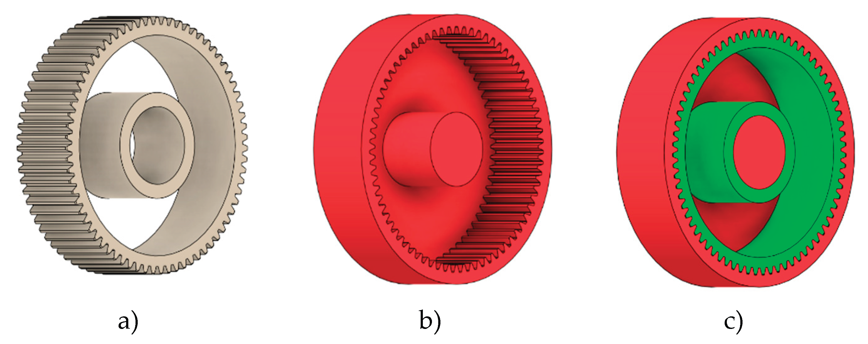
Figure 2.
Defining of constraints and support conditions for the spur gear model.

Figure 3.
Defining the maximum force acting on single gear tooth (continuous load).
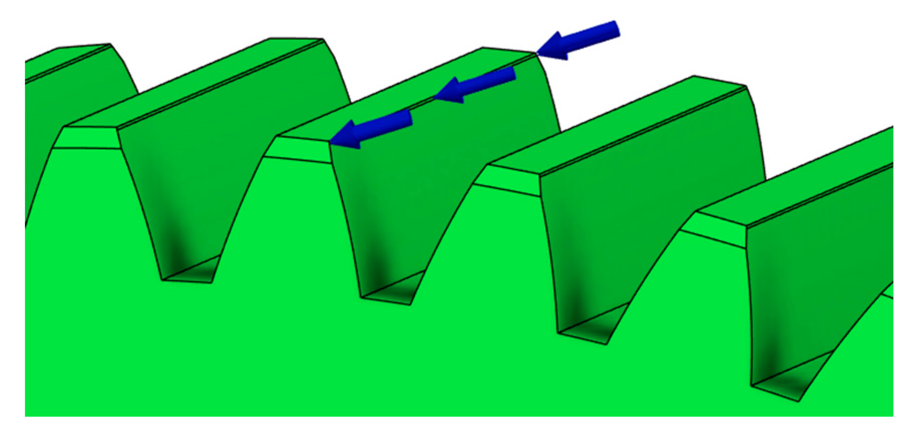
Figure 4.
Setting of total torque acting on spur gear.
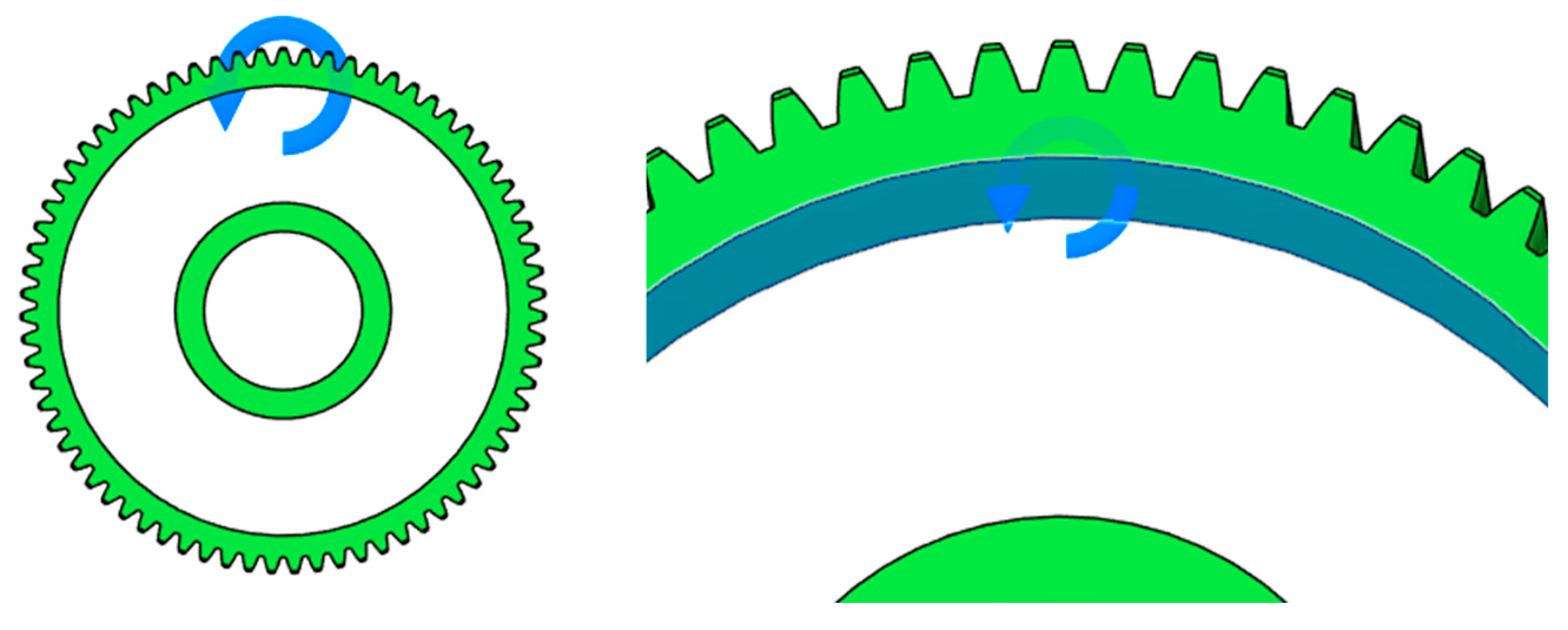
Figure 5.
Worst-case load model – all teeth simultaneously subjected to maximum force.

Figure 6.
Examples of structural solutions for lightening of spur gear bodies.

Figure 7.
Variants of lightening a spur gear body: (a) 10 circular holes without preserved material; (b) 10 circular holes with material preserved around the holes; (c) 6 holes without preserved material; (d) 6 holes with material preserved around the holes.
Figure 7.
Variants of lightening a spur gear body: (a) 10 circular holes without preserved material; (b) 10 circular holes with material preserved around the holes; (c) 6 holes without preserved material; (d) 6 holes with material preserved around the holes.
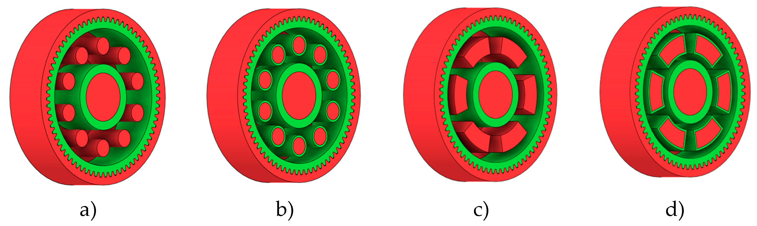
Figure 8.
Solid gear blank before optimization.
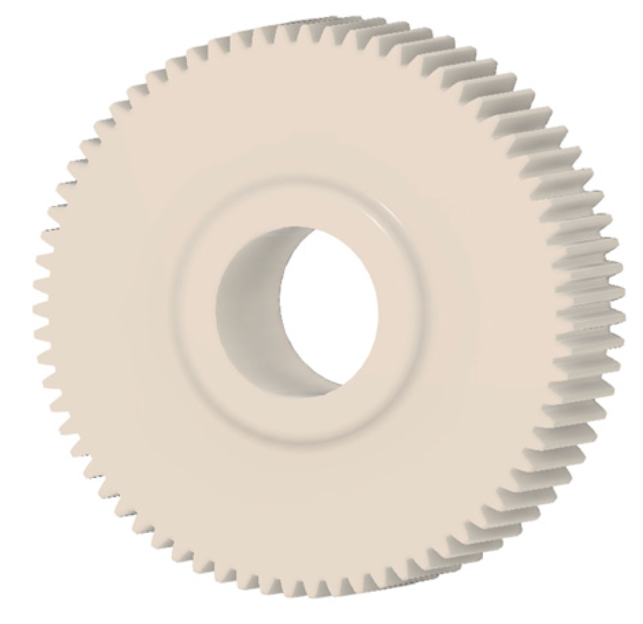
Figure 9.
Tooth deformation solved by FEM.
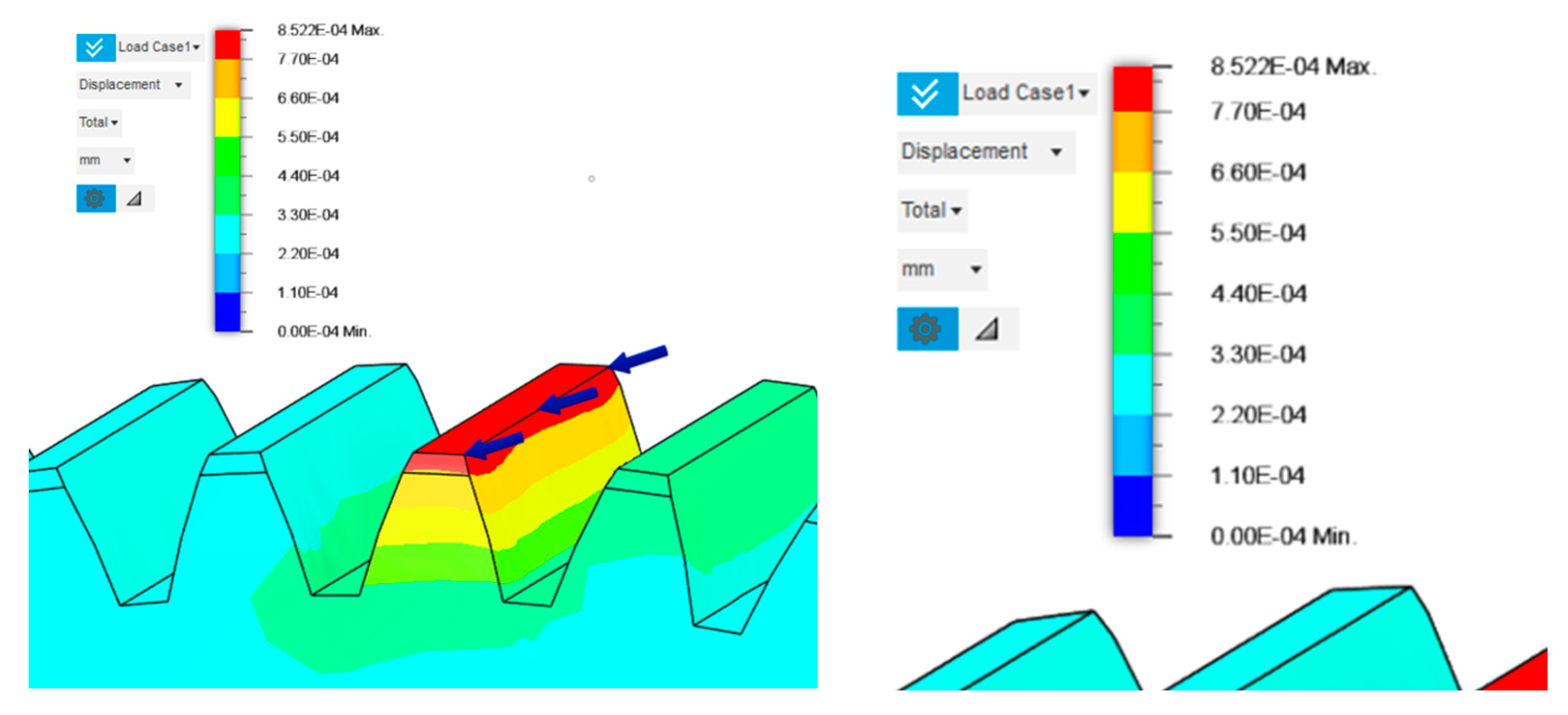
Figure 10.
Distribution of deformations above the lightening segment and outside of it.

Figure 11.
Analysis of the gear body shape with circular lightening holes depending on the manufacturing method.
Figure 11.
Analysis of the gear body shape with circular lightening holes depending on the manufacturing method.
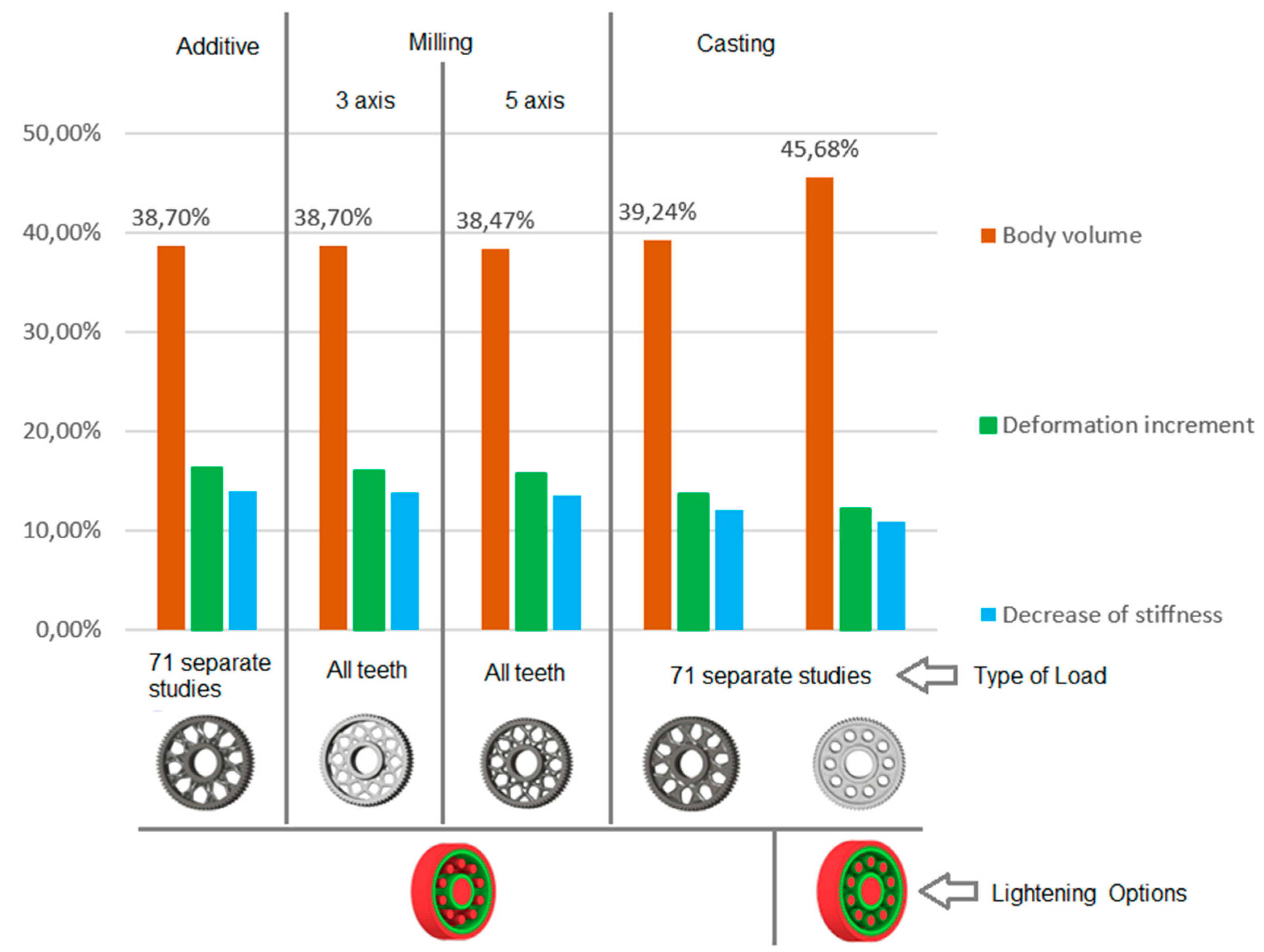
Figure 12.
Analysis of the gear body shape with lightening holes depending on the manufacturing method.
Figure 12.
Analysis of the gear body shape with lightening holes depending on the manufacturing method.
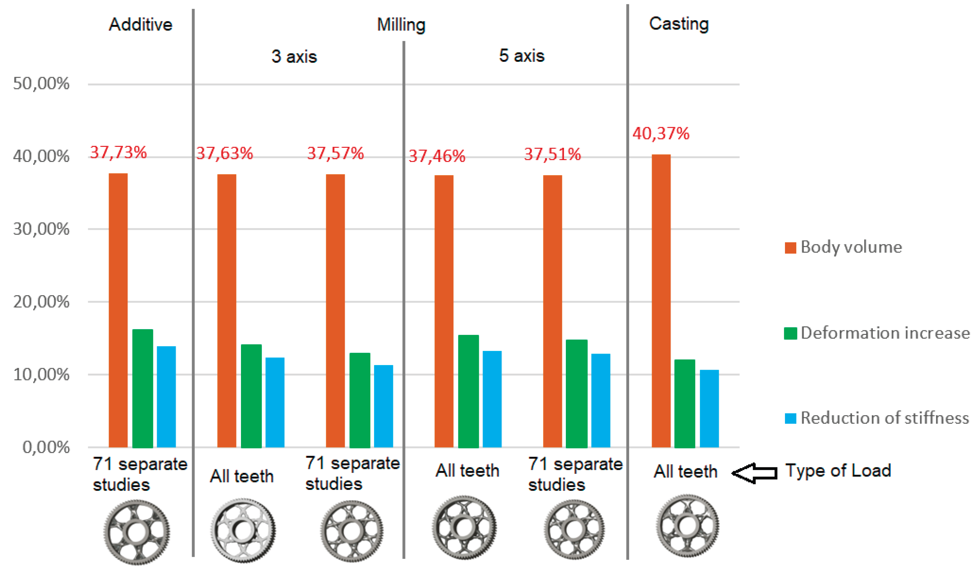

Table 1.
Shape generation with definition of basic geometric constraints.
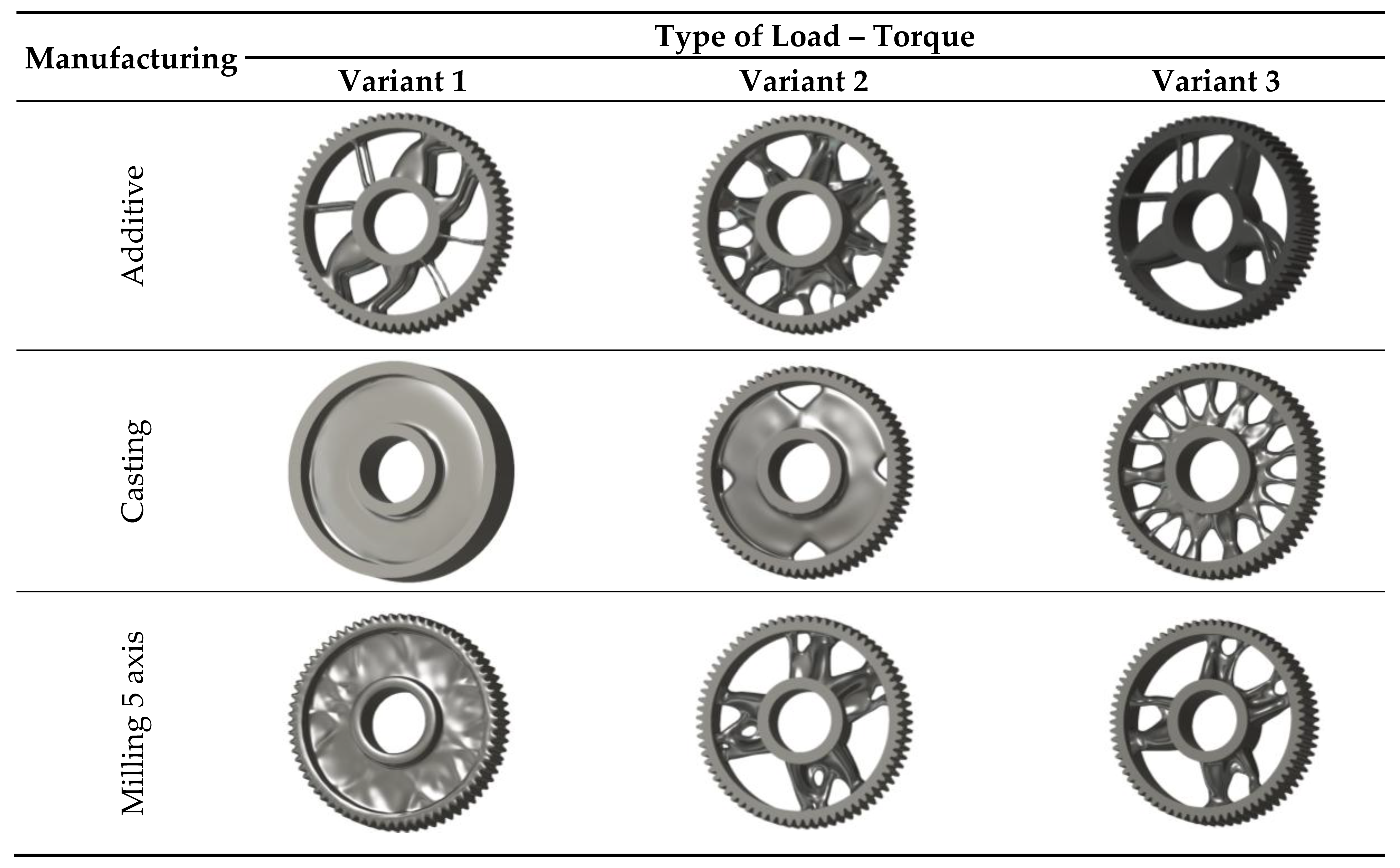
Table 2.
Results of generative design of the gear body with lightening holes.
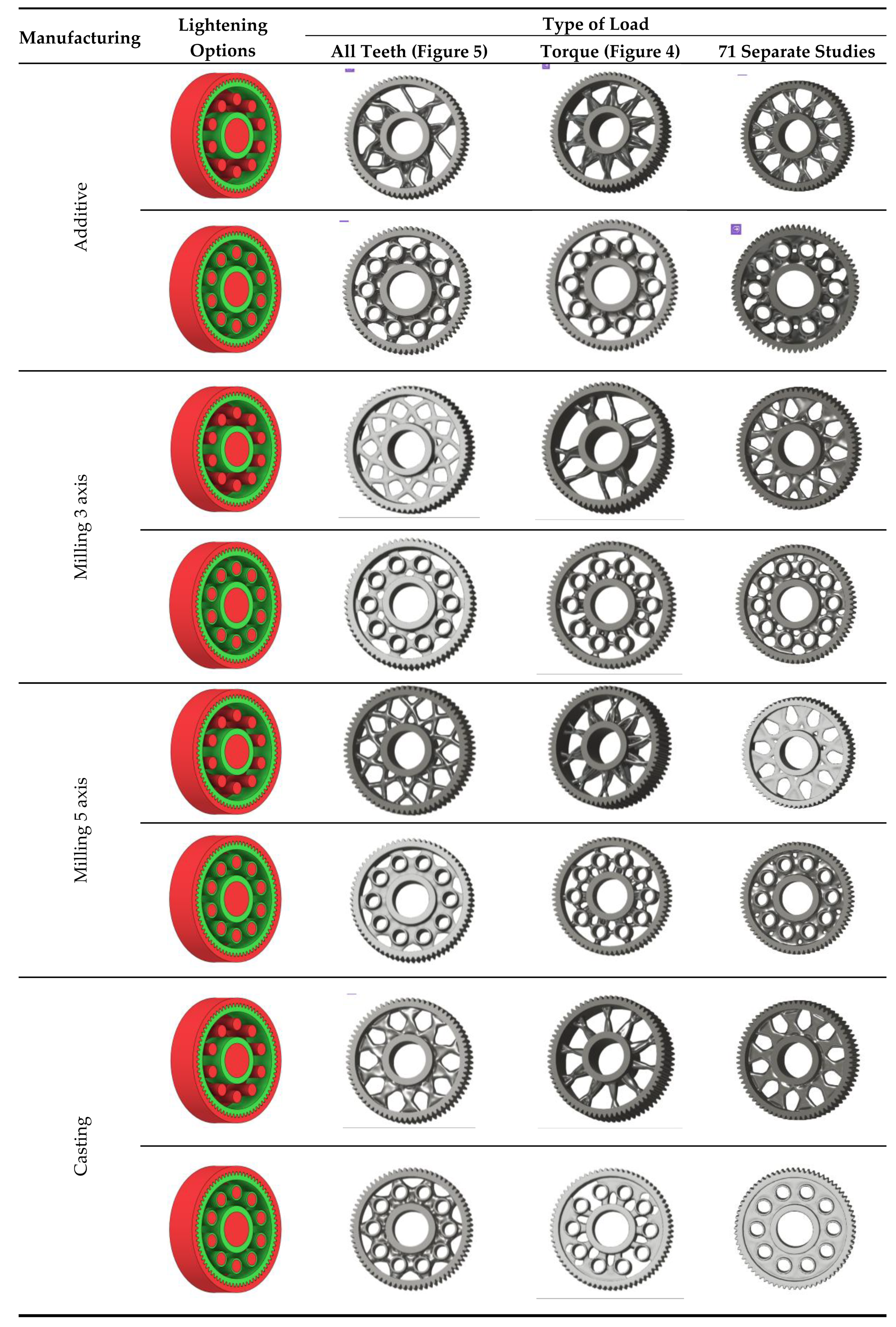
Table 3.
Unsuitable solutions of generated spur gear body shapes.

Table 4.
Results of generative design of the gear body with six lightening holes.
Disclaimer/Publisher’s Note: The statements, opinions and data contained in all publications are solely those of the individual author(s) and contributor(s) and not of MDPI and/or the editor(s). MDPI and/or the editor(s) disclaim responsibility for any injury to people or property resulting from any ideas, methods, instructions or products referred to in the content. |
© 2025 by the authors. Licensee MDPI, Basel, Switzerland. This article is an open access article distributed under the terms and conditions of the Creative Commons Attribution (CC BY) license (https://creativecommons.org/licenses/by/4.0/).
Copyright: This open access article is published under a Creative Commons CC BY 4.0 license, which permit the free download, distribution, and reuse, provided that the author and preprint are cited in any reuse.


