
Submitted:
28 November 2025
Posted:
28 November 2025
You are already at the latest version
Abstract
The moiré effect has been considered in various objects, such as coplanar layers, hollow shells, and volumetric three-dimensional objects (e.g., parallelepipeds, prisms, cylinders, and LED cubes). However, the moiré effect in refracting objects filled with a transparent substance (such as liquid or glass) has not yet been investigated. We performed a theoretical and experimental study of the moiré effect in rectangular and cylindrical containers with a refractive substance. The formulas for the magnification coefficient and the moiré period in rectangular and cylindrical refracting objects were obtained. Experiments confirm the theory. This study is essential for understanding the physical properties of the moiré effect with refraction. The results can be used to measure the level and refractive index.
Keywords:
moiré phenomenon
; moiré magnification
; refractive magnification
; moiré refraction
1. Introduction
The moiré effect is a physical phenomenon that occurs in superimposed periodic or nearly periodic structures or their projections [1,2]. The moiré patterns appear as relatively broad stripes, which period differs from the original structures.
Most often, the moiré effect is considered in coplanar layers [1,3,4,5,6]; particularly, in twistronics and two-dimensional materials [7,8,9,10], twisted bilayers [11,12,13], as well as interesting cases of tri- and multi-layered structures [14,15].
Sometimes (although relatively rarely), the effect is studied in non-coplanar layers [16,17,18] or hollow three-dimensional objects bounded by flat or curved surfaces of macro- [19,20,21,22,23,24] and nano-objects [25,26,27], including
b) non-parallel planes of a wedge (triangular prism) [19],
c) cylinder [20,21,22,23], in particular, single-walled (SWNT) [30,31,32] and double-walled nanotubes (DWNT) [33,34],
d) their combinations [35], and
e) multilayered volumetric structures (e.g., LED cubes) [36].
However, to the author’s knowledge, the moiré effect in objects filled with a refractive substance (e.g., thick glass or transparent containers filled with liquid) has not yet been investigated.
The paper examines rectangular and cylindrical containers. The former can be called a box. We use the first-order approximation (small angles).
2. Materials and Methods
Consider a symmetric 3D object filled with a refractive substance (such as water or glass), as shown in Figure 1. The surface of the liquid is horizontal (parallel to the xy-plane). We used the line grids with vertical lines (perpendicular to the xy-plane) attached to the object’s surfaces without folds or gaps. Thus, we consider flat facets (parallelepiped) and curved (cylinder).
The refraction is significant only on the frontal surface of an object (near the camera), but on the rear surface (far from the camera), refraction is not taken into account.
The origin is at the center of the object, see Figure 2. The observer (camera) is located at point C. The distance from the origin to the camera is L. The camera viewing angle is α:
where y0 is the ordinate of the intersection point (x0, y0) of the camera ray with the near surface, and l is the distance from the camera to the intersection.
In a filled object, the apparent (visible) size of the object is changed because of the refractive substance inside the object. The intersection points of the refracted and the extended rays with the far surface are (x2, y2) and (x1, y1). The refractive magnification M is the ratio of the visible size (how an object appears to our eyes or the camera) to the physical size (the physical intersection of the ray with the far surface),
where the physical and visual (perceived) sizes are:
Snell’s’ law in general:
and for small angles,
where n is the refractive index, i and r are the angles of incidence and refraction,
In the formulas above, the angle φ is the angle between the abscissa and the intersection point,
and the angle ψ is portion of the refraction angle above the line parallel to the abscissa.
Based on the geometry,
Thus, for small angles, the refractive magnification is
The ratio of grid wavenumbers/periods ρ is defined as
where k is the wavenumber and λ is the period.
The geometrical ratio of grids ρ is the ratio of the physical periods (as the grids are technically constructer). However, the effective size of the far grid changes due to the refraction in the filled object,
and thus
where M(n) is the refractive magnification coefficient for the far grid, which will be calculated in Sec. 3.1.
The fundamental property of the moiré effect [1,2] is that the moiré wavenumber is equal to the difference of the wavenumbers of the grids projected onto the same plane,
The projected wavenumbers and moiré wavenumbers will be calculated in Sec. 3.2.
For the parallelepiped, we use the relative quantity
where W is the half-width of the parallelepiped.
Similarly, in formulas related to the cylinder, we use relative quantities
where R is the radius of the cylinder.
3. Results
3.1. Refractive Magnification
3.1.1. Parallelepiped
The symmetric parallelepiped is shown in Figure 3. Both surfaces are parallel to the ordinate, and x0 - x1 = x0 - x2 = 2W. The angles are:
For small angles, Equations (10), (11) are as follows,
From Equation (12), we obtain the refractive magnification in the filled parallelepiped,
where the coefficient N is
N.B. In the water (n = 1.33), the coefficient N ≈ 0.5.
Using the relative quantity Equation (17) and the above coefficient, Equation (25) becomes,
For n > 1, the denominator is smaller than the numerator. Thus, M > 1, and a water layer (with parallel sides) magnifies images of objects behind it.
For , the refractive magnification . At large distances, the refractive magnification is in both water and air.
For n > 1, the derivative of Equation (27) is negative. Therefore, the refractive magnification as a function of the distance decreases from n to 1, as shown in Figure 4, where the calculated refractive magnification in water is slightly exceeds 1.
3.1.2. Cylinder
The geometry of our problem (see Figure 5) is similar to the central projection discussed in [2]. Note the second, imaginary point C2 at the intersection of the extended refracted ray with the abscissa; L2 and l2 are distances to it. The angles α and ψ are small, but the angles φ1 and φ2 are not.
According to [2], the coordinates of the intersection point of the camera ray with the cylindrical surface are:
where L is the distance from the center of the cylinder to the camera, and l is the distance from the camera to the intersection point:
where the upper sign refers to the concave half of the cylinder (far from the camera), and the lower sign refers to the convex half (near the camera).
3.1.2.1. Near Surface
On the near (refracting) surface, for small angles, we have from Equation (30),
From geometry, using Equation (31), the formulas Equations (28), (29) can be rewritten for small angles,
On the near surface, the incident angle given by Equation (7) can be expressed using Equation (34),
Then, from Equation (6),
From Equations (8), (36), (34), we obtain the first formula for ψ,
3.1.2.2. Far Surface
There are two intersections of the physical and extended rays with the far surface; for them, we have:
Therefore, in the first order approximation, the intersections 1 and 2 have the same abscissas but different ordinates.
Using geometry and Equations (32), (33), we obtain the second formula for ψ
Combining two Equations (37), (44) for ψ (small angle), we get
We solve Equation (45) for :
3.1.2.3. Refractive Magnification in a Cylinder
Substitute Equations (46), (37) into Equation (43),
Using the visible size Equations (3), (41), and the physical size Equations (4), (47), the refractive magnification in the cylinder according to Equation (2) is equal to
When = 1, . At large distances, the refractive magnification in the cylinder is constant and depends on the refractive index,
(For water, it is approximately 2.)
For n > 1, the derivative of Equation (48) with respect to distance is positive, so the function in water increases from n to 2.
The calculated refractive magnification in the cylinder for n = 1.33 is shown in Figure 6, where it is slightly less than 2 (at large distances, it is approximately twice the refractive magnification in the box).
3.2. Moiré Effect
3.2.1. Parallelepiped
Let us find the second period projected on the first plane of the empty rectangular container based on the geometry. From the similar triangles in Figure 3, given y2 = λ2, y1 = λ2’), we get
where can be called a projection coefficient. Correspondingly,
The first projected period coincides with itself. Then, according to the fundamental formula Equation (16), the moiré wavenumber is,
In the filled container, the far grid increases in the refracting substance (see Equation (15)), so using Equation (13) and the relative quantity Equation (17), we have
Substituting M◻(n) from Equation (27) into Equation (53), we obtain the moiré wavenumber in the parallelepiped,
The corresponding moiré period is
When , the function is zero. When ,
The period reaches infinity at the distance where the denominator is zero:
The derivative of the function under the modulus operator in Equation (55) is positive, so the function 1/k rises, reaching infinity at the intermediate point given by Equation (57). However, the period (the modulus of the inverse k) increases and decreases.
The calculated moiré period is shown in Figure 7 for air and water (n = 1 and 1.33, respectively); characteristic lines are also indicated.
3.2.2. Cylinder
The projected wavenumber of a cylindrical surface is known (see Equation (3.64) in [2]), see also [20] with a different position of the origin,
where the auxiliary quantity Λ is defined as
(For small angles, .)
The moiré wavenumber can be obtained from Equation (58) based on the fundamental formula Equation (16); and for small angles, we have,
Using the refractive magnification Equation (48), we obtain
The corresponding moiré period is
At , the period is
At ,
The asymptotes in air and water are, respectively,
The moiré period reaches infinity when the denominator of Equation (62) is zero:
The derivative of the function under the modulus in Equation (62) (the inverse k in Equation (61)) is positive, i.e., the function under the modulus in increasing. However, in water, the right branch of the period (the absolute value) decreases, so the functions in water and in air intersect. The intersection point Lx can be found from the condition
and
The calculated periods are shown in Figure 8 for air and water (ρ = 0.86); characteristic points and lines are also indicated.
3.3. Experiments
3.3.1. Refractive Magnification
The moiré magnification was measured by the apparent size of the entire grid attached to the far surface (the white lines with arrows in Figure 9 and Figure 10) photographed through the container above and below the surface of the liquid (the camera axis was horizontal, directed along the x-axis to the origin).
3.3.2. Moiré Period
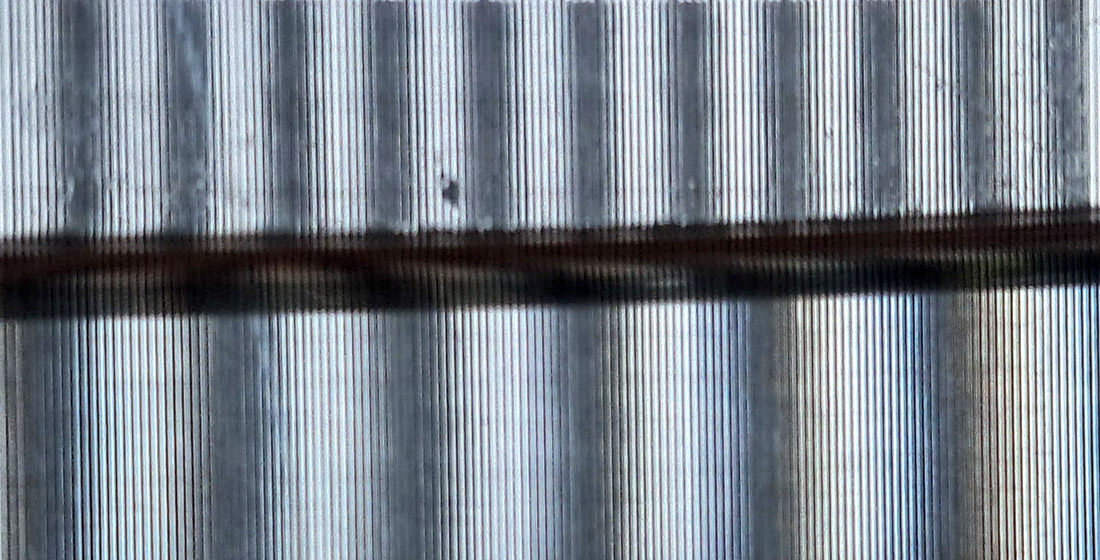
Examples of moiré patterns in the box and the cylinder with two grids at near and far surfaces are shown in Figure 12 and Figure 13. As in the previous experiment with a single grid (Figure 10, Figure 11), the camera axis was horizontal and directed to the origin; the photographs show the yz-plane above and below the water surface).
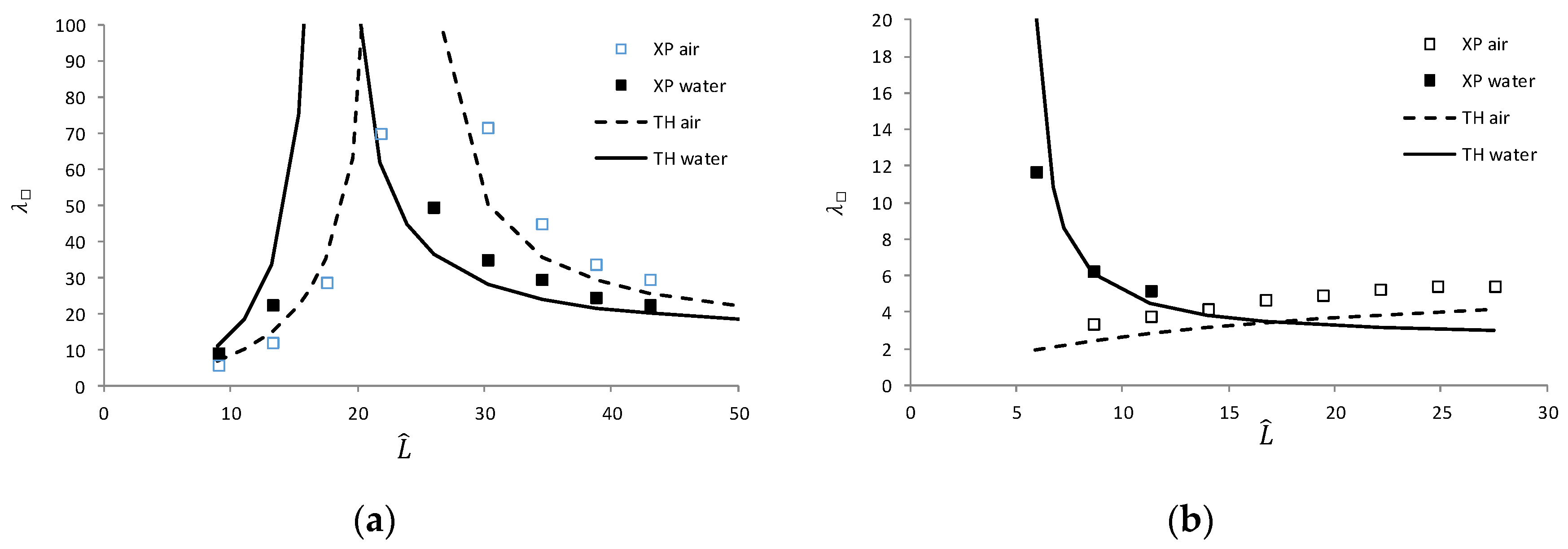
The moiré period was measured as follows. The size of several periods of the moiré patterns was measured in pixels. The known width of the grid was also measured in pixels, allowing the pixel-per-millimeter ratio to be calculated for a given photograph. Then the moiré period in mm can be determined. The results are presented in Figure 14 for the objects shown in Figure 12, Figure 13: the box with 2W = 4.8 cm (ρ = 1.09) and the cylinder with R = 3.7 cm (ρ = 0.86).
4. Discussion
The analytic expressions for a parallelepiped and a cylinder are somehow similar. The formal difference between the refractive magnification Equation (48) for a cylinder and the corresponding formula for a parallelepiped Equation (27) lies in the position of the coefficient N in the denominator. Similarly, Equations (55) and (62) differ in the signs and positions of the coefficients (1 ± ρ) and (N ± ρ).
In a cylindrical water tank, the accuracy of the refractive magnification measurements based on RMSE is lower than in a box, since the number of grid lines is smaller (e.g., 20 vs. 140). The deviation of the measured moiré period from the theory (RMSE) is about 25% for the box and cylinder, probably for the same reason, since the typical number of the moiré fringes was less than ten.
Note that the peak heights at a certain distance are theoretically infinite, and therefore, the data cannot be correctly presented in graphs. For this reason, the plots show a virtually random value instead of infinity. It should also be noted that the RMSE criterion may fail near sharp edges of functions that could theoretically be infinite, as in Figure 14.
According to Equation (27), the refractive magnification in the box at a short distance is , which is 33% greater than 1 for n =1.33; this is the case of a scuba diver underwater, for whom L << W. To independently confirm this value, one can recall that when wearing a flat scuba mask, objects underwater appear 33% larger than they are, as noted in [37,38,39].
Equation (55) with n = 1 is the functional analog of the formula for the moiré period in air [17], where the first grid is at the origin. The expression in parentheses in Equation (60) with M = 1 and ρ = 1 is equal to 2, i.e., the same coefficient as in Equation (3.115) in [2] (the moiré wavenumber in a single-layered cylinder without refraction).
Compared with the moiré effect without refraction, the moiré period in the rectangular box is similar, but the distance of the infinite period is shifted. However, in a cylinder, the ascending function is replaced by a descending one.
5. Conclusions
The moiré effect in flat and cylindrical objects with refraction was investigated. Formulas for the magnification coefficient and the moiré period were derived. The theory was confirmed experimentally. Previously published studies confirm the cases without refraction.
This study is important for understanding the physical properties of the moiré effect with significant refraction. The results can be used in practice for measuring the refractive index or the liquid level.
Funding
This research received no external funding.
Data Availability Statement
Dataset available on request from the author (the data are part of an ongoing study).
References
- Amidror, I. The Theory of the Moiré Phenomenon, Vol. I: Periodic Layers, 2nd ed.; Springer-Verlag: London, UK, 2009. [Google Scholar]
- Saveljev, V. The Geometry of the Moiré Effect in One, Two, and Three Dimensions; Cambridge Scholars: Newcastle Upon Tyne, UK, 2022. [Google Scholar]
- Sciammarella, C.A. Basic optical law in the interpretation of moiré patterns applied to the analysis of strains. Exp. Mech. 1965, 5(5), 154–160. [Google Scholar] [CrossRef]
- Yokozeki, S.; Kusaka, Y.; Patorski, K. Geometric parameters of moiré fringes. Appl. Opt. 1976, 15(9), 2223–2227. [Google Scholar] [CrossRef] [PubMed]
- Bryngdahl, O. Moiré: Formation and interpretation. JOSA 1974, 64(10), 1287–1294. [Google Scholar] [CrossRef]
- Dohnal, M. Moiré in a scanned image. Proc. SPIE 1999, 4016, 166–170. [Google Scholar]
- Yu, Y.; Van Winkle, M.; Bediakoa, D.K. Tuning interfacial chemistry with twistronics. Trends Chem. 2022, 4(10), 857–859. [Google Scholar] [CrossRef]
- Hennighausen, Z.; Kar, S. Twistronics: A turning point in 2D quantum materials. Electron. Struct. 2021, 3(1), 014004. [Google Scholar] [CrossRef]
- Wang, S.; Song, J.; Sun, M.; Cao, S. Emerging characteristics and properties of moiré materials. Nanomaterials 2023, 13(21), 2881. [Google Scholar] [CrossRef]
- Khurana, R.K. Moiré patterns in nanomaterial. Mat. Sci. Semicon. Proc. 2022, 140, 106406. [Google Scholar] [CrossRef]
- Arrighi, E.; Nguyen, V.-H.; Di Luca, M.; Maffione, G.; Hong, Y.; Farrar, L.; Watanabe, K.; Taniguchi, T.; Mailly, D.; Charlier, J.-C.; Ribeiro-Palau, R. Non-identical moiré twins in bilayer graphene. Nat Comm. 2023, 14, 8178. [Google Scholar] [CrossRef]
- de Jong, T.A.; Benschop, T.; Chen, X.; Krasovskii, E.E.; de Dood, M.J.A.; Tromp, R.M.; Allan, M.P.; van der Molen, S.J. Imaging moiré deformation and dynamics in twisted bilayer graphene. Nat Comm. 2022, 13, 70. [Google Scholar] [CrossRef]
- Latychevskaia, T.; Escher, C.; Fink, H.-W. Moiré structures in twisted bilayer graphene studied by transmission electron microscopy. Ultramicroscopy 2019, 197, 46–52. [Google Scholar] [CrossRef] [PubMed]
- Ren, W.; Zhu, Z.; Zhang, X.; Luskin, M.; Wang, K. Review: moiré-of-moiré superlattice in twisted trilayer graphene. J. Phys.: Condens. Matter 2025, 37, 353001. [Google Scholar] [CrossRef] [PubMed]
- Xu, P.; Qi, D.; Schoelz, J.K.; Thompson, J.; Thibado, P.M.; Wheeler, V.D.; Nyakiti, L.O.; Myers-Ward, R.L.; Eddy Jr., C.R.; Gaskill, D.K.; Neek-Amal, M.; Peeters, F.M. Multilayer graphene, moiré patterns, grain boundaries and defects identified by scanning tunneling microscopy on the m-plane, non-polar surface of SiC. Carbon 2014, 80, 75–81.
- Saveljev, V.; Kim, S.-K. Simulation of moiré effect in 3D displays. J. Opt. Soc. Korea 2010, 14, 310–315. [Google Scholar] [CrossRef]
- Saveljev, V.; Kim, S.-K. Simulation and measurement of moiré patterns at finite distance. Opt. Express 2011, 20, 2163–2177. [Google Scholar] [CrossRef]
- Sciammarella, C.A.; Chiang, F.-P. Gap effect on moiré patterns. ZAMP 1968, 19, 326–333. [Google Scholar] [CrossRef]
- Saveljev, V.; Son, J.-Y.; Kim, Y.; Park, J.-G.; Heo, G. Moiré patterns in non-parallel surfaces such as prism. JOSA A 2020, 37(2), 336–345. [Google Scholar] [CrossRef]
- Saveljev, V.; Han, W.; Lee, H.; Kim, J.; Kim, J. Moiré effect in double-layered coaxial cylinders. Appl. Opt. 2020, 59(18), 5596–5607. [Google Scholar] [CrossRef]
- Saveljev, V.; Lee, H.; Kim, J. Physical model of the moiré effect in cylindrical structures. J. Korean Phys. Soc. 2017, 71, 934–945. [Google Scholar] [CrossRef]
- Saveljev, V. Moiré effect in cylindrical objects. J. Korean Phys. Soc. 2016, 68(9), 1075–1082. [Google Scholar] [CrossRef]
- Saveljev, V. The off-axis moiré effect in double-layered cylinder. J. Mod. Opt. 2023, 70(1), 39–51. [Google Scholar] [CrossRef]
- Saveljev, V. Moiré effect in 3D structures. In Advances in Optics: Reviews, vol. 1; Yurish, S.Y.; Ed., International Frequency Sensor Association Publishing, Barcelona, Spain, 2018, pp. 61–93.
- Sadan, M.B.; Houben, L.; Enyashin, A.N.; Seifert, G.; Tenne, R. Atom by atom: HRTEM insights into inorganic nanotubes and fullerene-like structures. Proc. Natl. Acad. Sci. U.S.A. 2008, 105, 15643–15648. [Google Scholar] [CrossRef] [PubMed]
- Warner, J.H.; Young, N.P.; Kirkland, A.I.; Briggs, G.A.D. Resolving strain in carbon nanotubes at the atomic level. Nat. Mater. 2011, 10, 958–962. [Google Scholar] [CrossRef] [PubMed]
- Suenaga, K.; Wakabayashi, H.; Koshino, M.; Sato, Y.; Urita, K.; Iijima, S. Imaging active topological defects in carbon nanotubes. Nat. Nanotechnol. 2007, 2(6), 358. [Google Scholar] [CrossRef]
- Bell, G.; Craig, R.; Simmiss, T. Moiré interference in multilayered displays. J. Soc. Inf. Disp. 2007, 15(11), 883–888. [Google Scholar] [CrossRef]
- Saveljev, V.; Kim, S.-K.; Kim, J. Moiré effect in displays: a tutorial. Opt. Eng. 2018, 57(3), 030803. [Google Scholar] [CrossRef]
- Zhou, X.; Xie, J.; Li, G.; Zhang, J.; Xia, M.; Luo, W.; Shi, Z. Moiré-induced band-gap opening in one-dimensional superlattices of carbon nanotubes on hexagonal boron nitride. Phys. Rev. B 2022, 105, 115433. [Google Scholar] [CrossRef]
- Konevtsova, O.V.; Roshal, D.S.; Rochal, S.B. ; Moiré patterns and carbon nanotube sorting. Nano Futures 2022, 6(1), 015005. [Google Scholar] [CrossRef]
- Tu, J.F. TEM nano-moiré pattern analysis of a copper/single walled carbon nanotube nanocomposite synthesized by laser surface implanting. C-J. Carbon Res. 2018, 4, 19. [Google Scholar] [CrossRef]
- Wittemeier, N.; Verstraete, M.J.; Ordejon, P.; Zanolli, Z. ; Interference effects in one-dimensional moiré crystals. Carbon 2022, 186, 416–422. [Google Scholar] [CrossRef]
- He, M.; Xu, Z.; Shang, D.; Zhang, X.; Zhang, H.; Li, D.; Jiang, H.; Kauppinen, E.; Ding, F. Is there chiral correlation between graphitic layers in double-wall carbon nanotubes? Carbon 2019, 144, 147–151. [Google Scholar] [CrossRef]
- Saveljev, V.; Heo, G. Moiré effect in combined planar and curved objects. JOSA A 2024, 41(10), 1884–1892. [Google Scholar] [CrossRef]
- Saveljev, V. Moiré effect in multilayered 3D lattice. Appl. Opt. 2023, 62(11), 2792–2799. [Google Scholar] [CrossRef]
- Luria, S.M.; Kinney, J.A.S. Underwater Vision. Science 1970, 167(3924), 1454–1461. [Google Scholar] [CrossRef]
- Adolfson, J.; Berghage, T. Perception and Performance under Water; John Wiley & Sons: Chichester, UK, 1974. [Google Scholar]
- K. Shreeves, PADI Open Water Diver Manual. PADI: Rancho Santa Margarita, CA, USA, 2007.
Figure 1.
Layout of camera and grids.
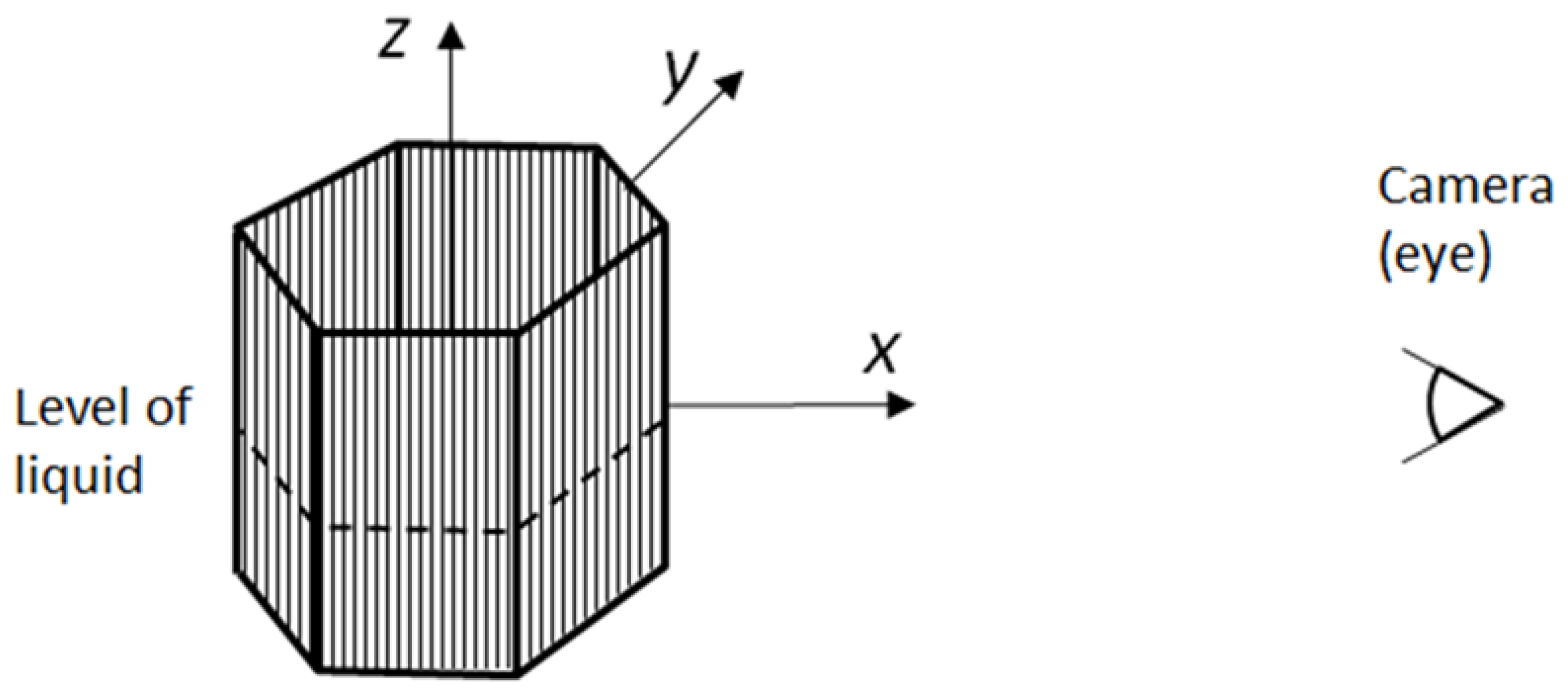
Figure 2.
The refracted ray in a symmetric object in the xy-plane.
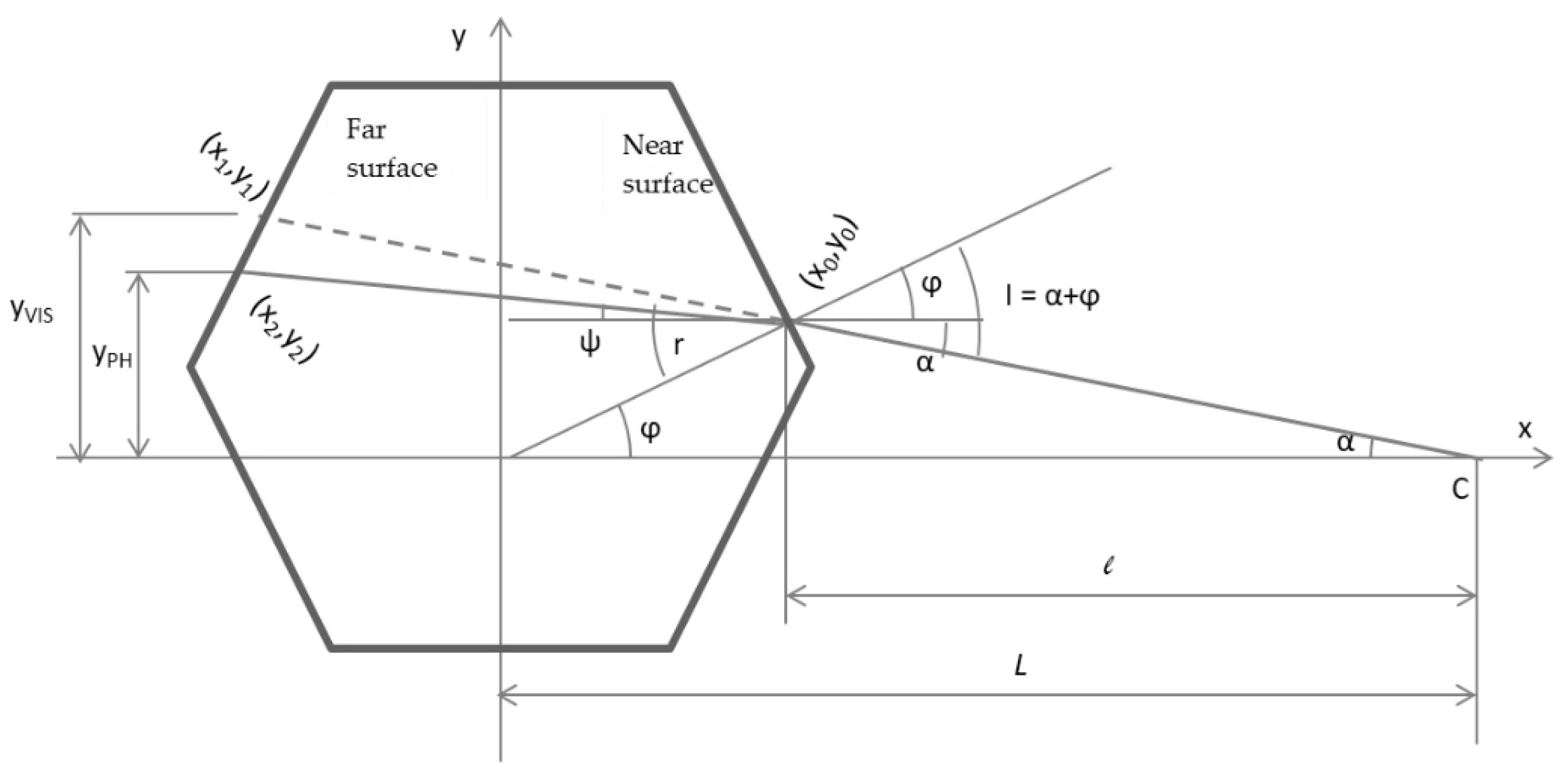
Figure 3.
Rays in a parallelepiped in the xy-plane.
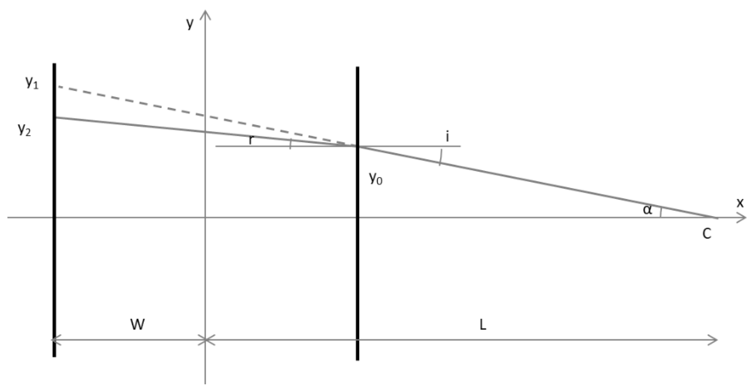
Figure 4.
Refractive magnification vs. relative distance in the box.
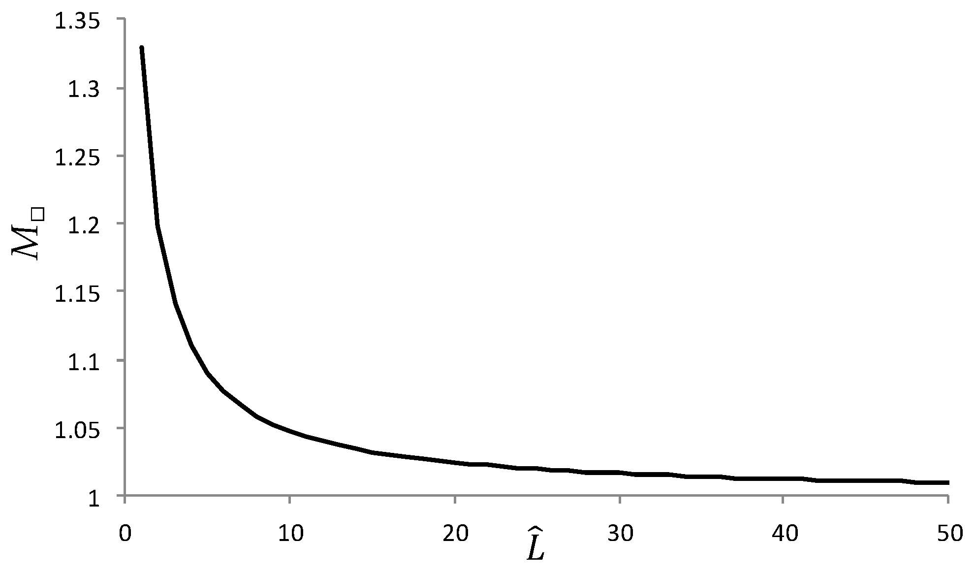
Figure 5.
Rays in a cylinder in the xy-plane.
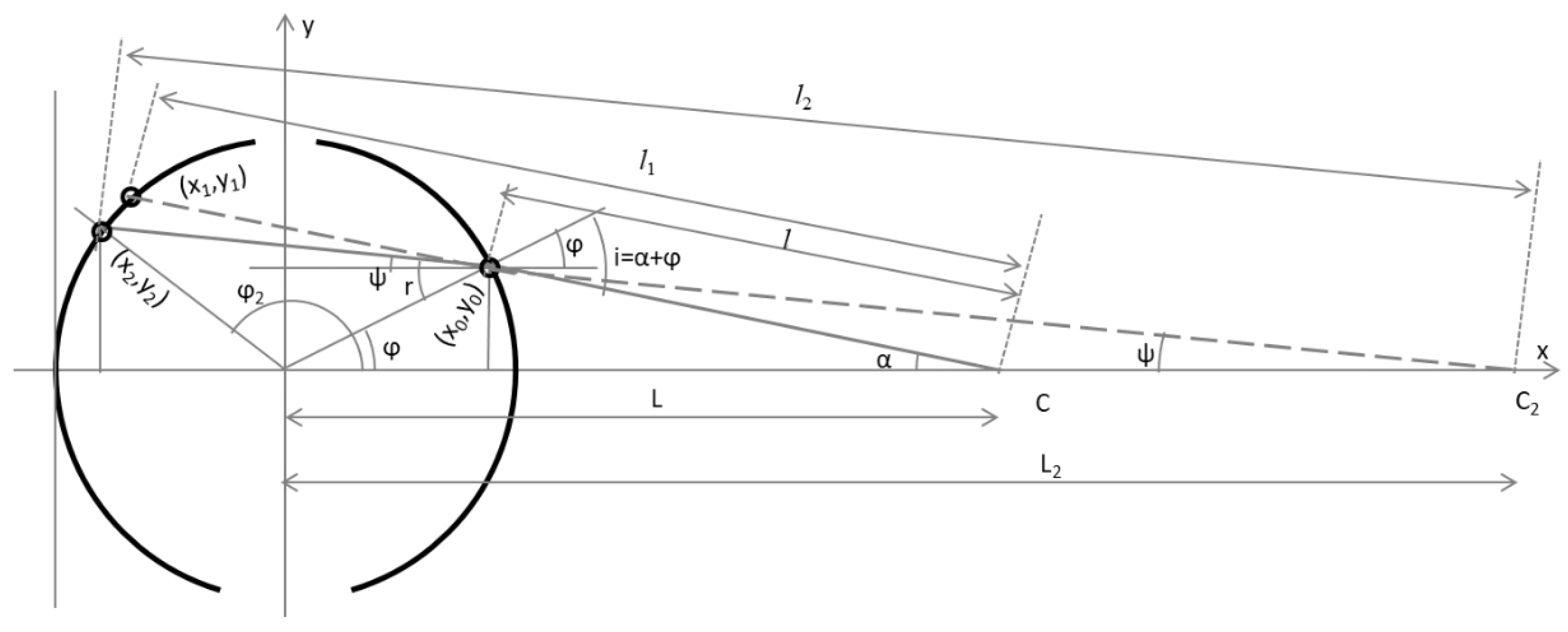
Figure 6.
The refractive magnification vs. relative distance in cylnder.
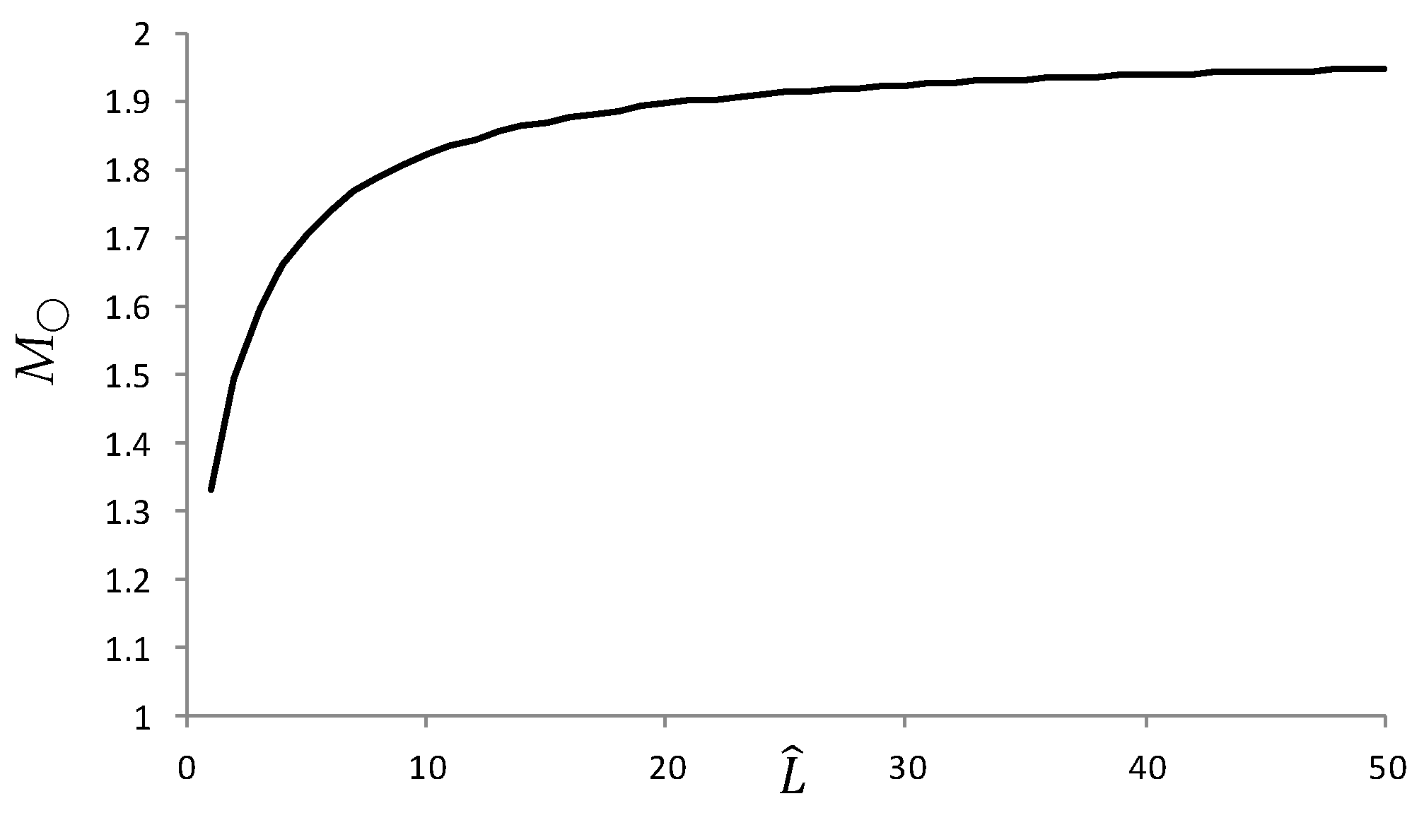
Figure 7.
Moiré period (mm) vs. relative distance in empty and filled boxes for λ1 = 1 mm, ρ = 1.09.
Figure 7.
Moiré period (mm) vs. relative distance in empty and filled boxes for λ1 = 1 mm, ρ = 1.09.
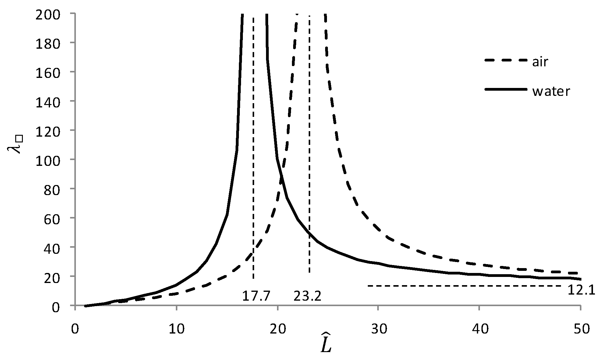
Figure 8.
Moiré period (mm) vs. relative distance in empty and filled cylinders with λ1 = 1 mm.
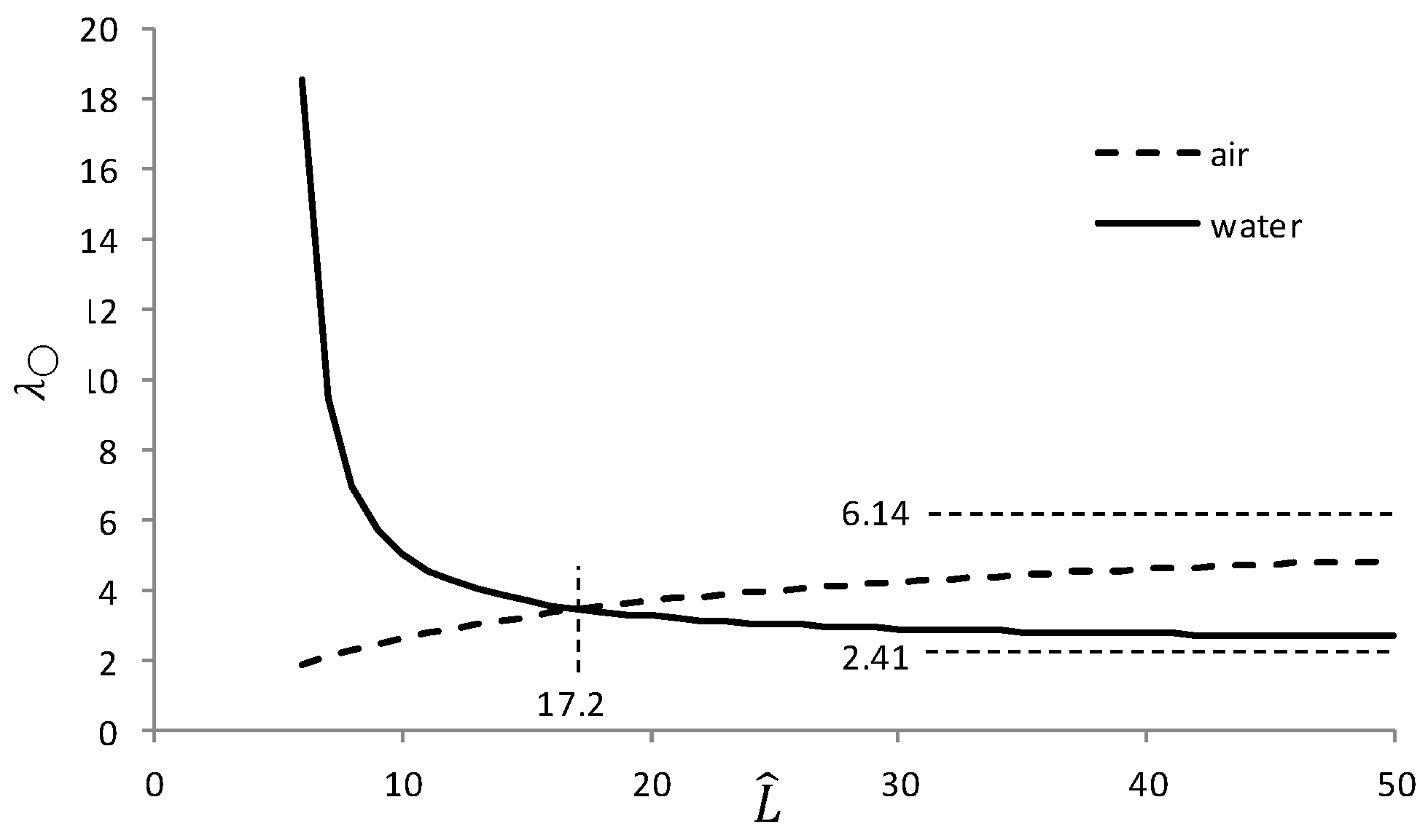
Figure 9.
Grid above and below the water surface in the box (yz-plane).
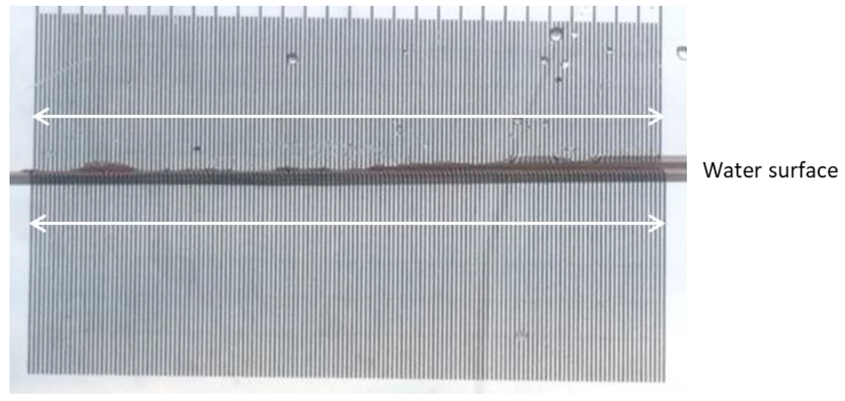
Figure 10.
Grid above and below the water surface in the cylinder (yz-plane).
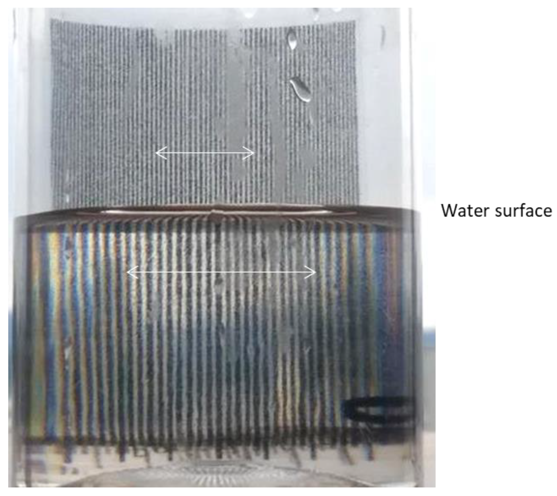
Figure 11.
Refractive magnification as a function of relative distance (a) in the box and (b) in the cylinder. Theoretical data are indicated by a line, experimental data by square markers.
Figure 11.
Refractive magnification as a function of relative distance (a) in the box and (b) in the cylinder. Theoretical data are indicated by a line, experimental data by square markers.
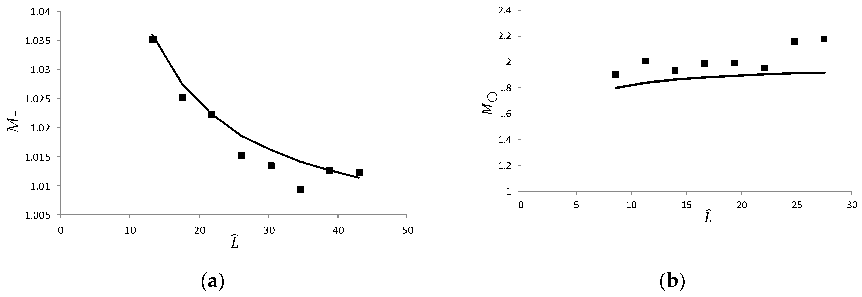
Figure 12.
Experimental photograph of the moiré patterns in the box.
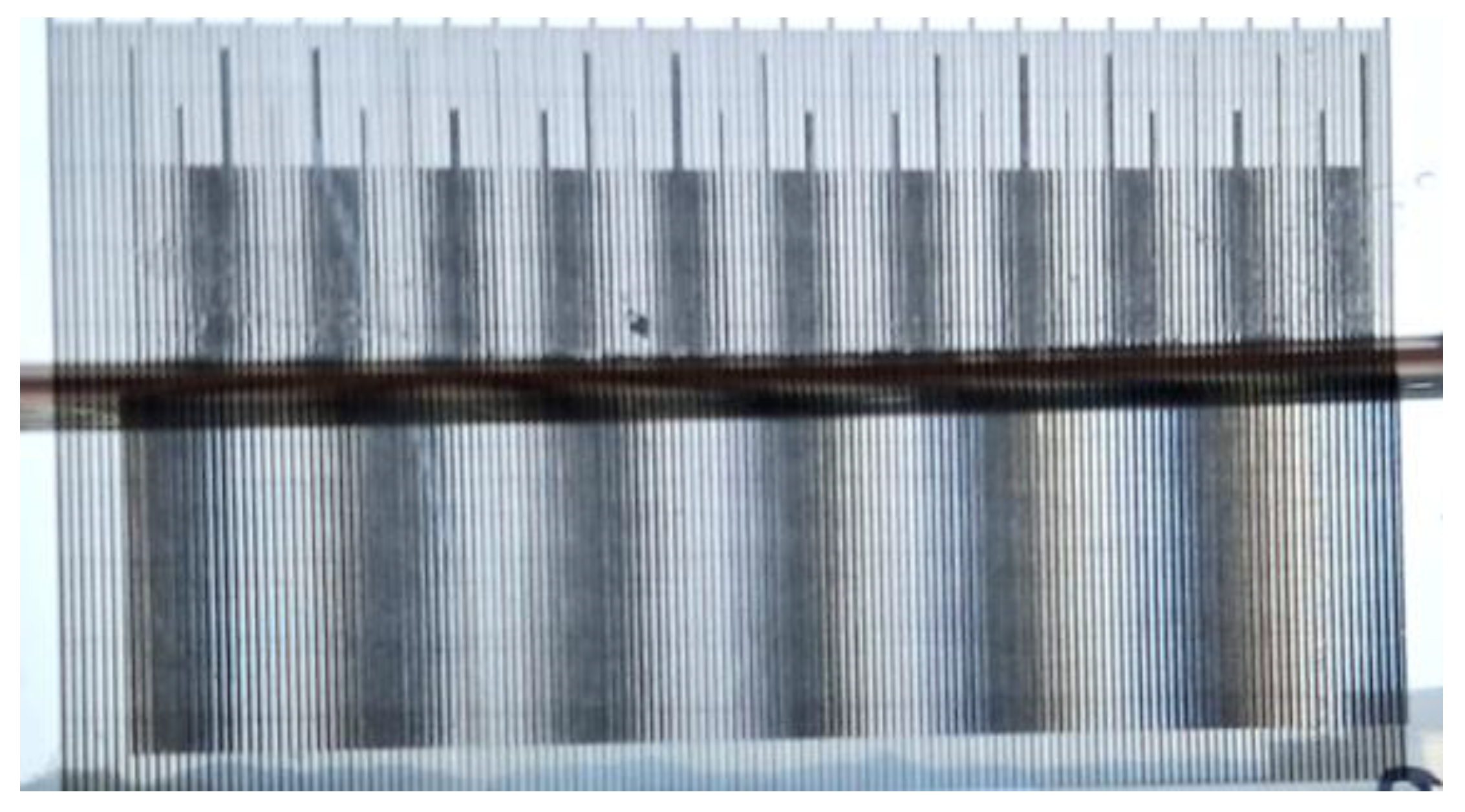
Figure 13.
Experimental photograph of the moiré patterns in the cylinder.
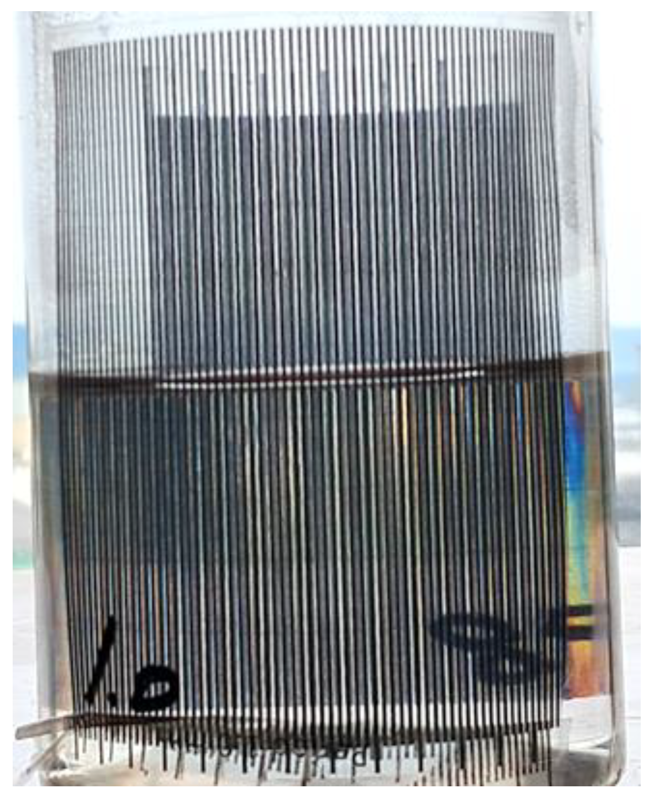
Figure 14.
Dependence of the moiré period on the relative distance (a) in a box, (b) in a cylinder. Theoretical data are indicated by lines (solid in water, dashed in air), experimental data by square markers (filled in water, empty in air).
Figure 14.
Dependence of the moiré period on the relative distance (a) in a box, (b) in a cylinder. Theoretical data are indicated by lines (solid in water, dashed in air), experimental data by square markers (filled in water, empty in air).
Disclaimer/Publisher’s Note: The statements, opinions and data contained in all publications are solely those of the individual author(s) and contributor(s) and not of MDPI and/or the editor(s). MDPI and/or the editor(s) disclaim responsibility for any injury to people or property resulting from any ideas, methods, instructions or products referred to in the content. |
© 2025 by the authors. Licensee MDPI, Basel, Switzerland. This article is an open access article distributed under the terms and conditions of the Creative Commons Attribution (CC BY) license (http://creativecommons.org/licenses/by/4.0/).
Copyright: This open access article is published under a Creative Commons CC BY 4.0 license, which permit the free download, distribution, and reuse, provided that the author and preprint are cited in any reuse.


