Submitted:
22 November 2025
Posted:
24 November 2025
You are already at the latest version
Abstract
The first significant discovery of oil on the Norwegian Continental Shelf was the Ekofisk field discovered in 1970. The drilling was done in 77 m water depth at a location in the Mid-North Sea about 250 km from the southern coast of Norway. As there were no previous Norwegian onshore facilities for landing the oil on the Norwegian coast, an export pipeline was built from Ekofisk to Emden, in Germany.
However, over the 55 years since then, there have been several hundred oil and gas discoveries made in the three seas hugging the Norwegian coastline, e.g., the North Sea, Norwegian Sea, and the Barents Sea. During the first developments, like Statfjord, Gullfaks, and Heidrun there was a very steep learning curve within many disciplines, such as survey and mapping, feature interpretation and seafloor process knowledge. Therefore, numerous research and development projects (such as the ‘Statfjord Transportation System Project’ STSP) were performed before infrastructure and facility development could be done in earnest.
We had to face the fact that the seafloor was very different from the land surface in ways of active and past sedimentary processes. We were familiar with phenomena related to groundwater, but in the seafloor sediments, there were also trapped gases that could cause serious problems, immediately, or later in the lifetime of the installations. We, therefore, had to address numerous unknown aspects as they manifested themselves.
Furthermore, we had to work intimately with governmental authorities to solve the challenges and to work in a transparent manner, for the sake of trustworthiness. As an example, hundreds of deep-water coral reefs were discovered from 1986 to 1990, located on the seafloor off Mid-Norway mainly because of reconnaissance mapping for the 200 km long pipeline route from Heidrun field to the coast. Any industrial activity in these areas obviously had to avoid damaging these ecosystems.
It became necessary to work intimately with Norwegian biological and environmental research institutions and with the Norwegian environmental protection agency. This proved to be especially important for the Haltenpipe Development Project (HDP), where the 200 km long pipeline route would have to cross through locations with high abundances of deep-water coral reefs. All survey information, including visual inspection and sampling of sediments had to be treated with trust and transparency, for practical reasons, i.e., to prevent loss of valuable time and delayed progress.
Keywords:
deep-water coral reefs
; haltenpipe development project (HDP)
; ‘the norwegian model’
; world war 1 and 2 mines
; archaeologically protected objects
; national supervision and control
; development of an oil industry
; protection of nature and environment
; shallow gas hazard
1. Introduction
After oil and gas was found on the Norwegian Continental Shelf, the Norwegian industrial authorities made rules and regulations for how the shelf could be developed. The rules were very strict with respect to protection of existing activities and environments on the shelf, such as fisheries and other important natural features (‘The ten oil commandments’: - The Norwegian Model, see below). There were also special features to become aware of and handle in an adequate manner, such as military ordinance (ammunition dumps and World War 1 and 2 mines), telegraph cables and other seafloor infrastructure, as well as shipwrecks older than 100 years (archaeologically protected objects).
Statoil, the Norwegian State oil company became one of the leading and dominating companies operating on the Norwegian continental shelf. However, compared with other, international companies, such as ESSO (Exxon), Conoco, Phillips, Shell, Elf and some others (including the French company, Total and the Italian, Eni), Statoil was, at first, reckoned as an apprentice, without international experience from offshore field developments, pipe construction and laying, etc. Therefore, Statoil had to team up with some of the bigger and more experienced companies. As a geophysiscist and engineer and as a new employee (in June 1976), I was given the task to participate in- and lead Statoil’s field development team with respect to the seafloor and its many challenges for field development and transport pipes placed on the seafloor.
2. Materials and Methods
This article builds on the author’s 38 year long experience as a senior engineer and academic engaged in the development of Statoil and other oil companies’ field developments, and projects. It also relies on internal and public reports on some of the aspects.
3. Results
3.1. Historical and Political Background
The Storting (parliament) approved a set of recommendations on 7 June 1971 which analysed many issues of principle. This analysis was summed up in what was later called – “the 10 oil commandments”. [1].
A summary of what was to become the prevailing Norwegian policy on oil and gas in the following years is presented below [1]:
1. National supervision and control must be ensured for all operations on the NCS (Norwegian continental shelf).
2. Petroleum discoveries must be exploited in a way which makes Norway as independent as possible for its supplies of crude oil.
3. New industry will be developed based on petroleum.
4. The development of an oil industry must take necessary account of existing industrial activities and the protection of nature and the environment.
5. Flaring of exploitable gas on the NCS must not be accepted except during brief periods of testing.
6. As a general rule, petroleum from the NCS must be landed in Norway, except in those cases where socio-political considerations dictate a different solution.
7. The State must become involved at all appropriate levels and contribute to a coordination of Norwegian interests in Norway’s petroleum industry as well as the creation of an integrated oil community which sets its sights both nationally and internationally.
8. A State oil company will be established which can look after the government’s commercial interests and pursue appropriate collaboration with domestic and foreign oil interests.
9. A pattern of activities must be selected north of the 62nd parallel which reflects the special socio-political conditions prevailing in that part of the country.
10. Large Norwegian petroleum discoveries could present new tasks for Norway’s foreign policy.
These 10 sentences emphasised that the most important goal was to secure national supervision and control. Norway was to become independent with respect to crude oil supplies. To ensure that, offshore production was to be landed directly in the country. New petroleum-based industrial activity was also to be created, and the government would support an integrated Norwegian oil community. In addition, a state-owned Norwegian oil company would be established to look after the state’s commercial interests and to maintain appropriate collaboration with both domestic and foreign oil interests. This declaration is regarded as fundamental for further development of the legislative framework and practical policies related to Norway’s petroleum sector. Its content enjoyed cross-party support. (Recommendation from the reinforced industry committee on prospecting for and recovering submarine natural resources on the Norwegian continental shelf [2].
3.2. The Statfjord Transportation System Project (STSP), 1976-1979
The state-owned oil and gas company ‘Statoil’ was founded in 1972. “When Arve Johnsen (Statoil’s first CEO) was a Fulbright scholar in the USA, he learnt about the Standard Oil company and its head, John D Rockefeller, who used his pipelines to crush his competitors. Thus, he was aware of the strategic importance of transport systems long before becoming CEO of Statoil. That underpinned the pressure he put on Phillips Petroleum in 1973-74 over control of the Norpipe pipelines from Ekofisk. Similarly, Statoil pushed hard to secure an oil and/or gas pipeline from Norway’s share of Statfjord (oil and gas field) to the Norwegian mainland.
The oil pipeline was not laid because the Storting (parliament) decided in June 1976 that Statfjord crude should be loaded directly into shuttle tankers. But a gas link was still possible, since the Storting had also asked Statoil to conduct a two-year programme of planning and studies for a gas gathering pipeline from Statfjord to shore. [1].
As a geophysicist with a degree in meteorology and oceanography from the University of Bergen, I applied for a position in Statoil’s technical department, who sought for a ‘seafloor specialist’, for new and challenging offshore pipelines. The main challenge for the technical department was to find a safe way to cross the ‘Norwegian Trench’, a 320 metres deep trough between some of the oil and gas fields and the SW Norwegian coast. Thus, I belonged to the specialist group of ‘The Statfjord Transportation System Project’ (STSP), who was a multi-national and multi-company group directed to solve the technical challenges to cross the Norwegian Trench and transport gas from Statfjord to shore through a 36’’ steel pipeline. We had a maximum of three years to do this work, and to demonstrate that all challenges would be solved, even that of dealing with pipeline burst and repair situation at 320 m water depth. This work was high-priority and high cost led by Statoil.
3.3. STSP-Challenges: High-Resolution Mapping and ‘Pockmark Craters’
Within my speciality field, which was to determine ‘seafloor conditions for safe pipelaying’, we had two main challenges that we had to resolve:
- 1)
- How to map large portions of the seafloor to such a high resolution that we could identify ‘safe’ corridors from the Statfjord field across the Norwegian Trench and through the rugged skerry zone of the Norwegian coast?
- 2)
- An understanding of the processes behind the newly discovered up to 100 m wide and 8 m deep ‘pockmark craters’ [3]. in the seafloor were formed? Such features were discovered off Nova Scotia a few years earlier and had also been observed in the Norwegian Trench.
Luckily, we had specialist academic groups in Norway and elsewhere (including the Institute for Continental shelf research, IKU, in Trondheim) that we could team up with and employ for short periods of time. We found that special new tools were needed to efficiently map large areas of the seafloor. In addition to using the common hull-mounted echosounder, we also needed to employ newly developed side-scan sonars and deep-towed echosounders, which were towed behind the survey vessels. In this way, we solved the resolution problem, by towing the echo sounder and side-scan sonar closer to the seafloor surface.
I am proud to say that some of our findings were not necessarily kept secret, as is normally the case in the international oil and gas business. This means that some of our analyses with respect to equipment and methods to map the seafloor efficiently could be shared internationally. This was deliberately done because we wanted as many specialists as possible to direct us in the best way, to reach our goals. We were, therefore, able to publish some of the results more-or-less immediately after approval from the project managers. The possibility to visit specialist conferences in Norway, Europe and the USA, and share some of our findings, proved to be a great benefit for the STSP.
The question on how the mysterious pockmark craters were formed in fine-grained seafloor sediments, mainly consisting of clay, took some time to resolve. There were two main theories for their formation:
- a)
- They were caused by processes of freezing and thawing during the last ice age. This theory was called the ‘dead-ice’ theory.
- b)
- They were caused by shallow gas seeping through the seafloor at locations of weakness in the clay sediments. This was called the ‘shallow gas’ theory.
It should be noted that a) is a passive model, where the pockmarks were formed during glaciation and did not develop thereafter, whereas b) is a model which accepts that new pockmarks may develop. After having interpreted all data accumulated during three years of STSP, we decided that the shallow gas theory was the most likely solution. This was also proved to be correct, in 1983, as I will show later. However, for the STSP project it meant that pockmarks must be avoided by pipelines, as they are liable to alter their topography over time, which would represent a hazard for the pipeline.
3.4. Unknown Seafloor Processes and Features Were Discovered (Methane Carbonates and WW-I Mines)
Immediately following the STSP, the task of constructing and laying a 36’’ steel pipeline from Statfjord to Norway became a reality (named the Statpipe project). Our survey group were responsible for finding the right pipeline route across the Norwegian Trench and through the rugged skerry zone, encountered numerous challenges. We had plenty of mapping to achieve, and numerous visual seafloor investigations to do over the next two years.
During one such investigation, using an ROV (remotely operated vehicle), we managed to document that pockmarks were produced by the natural transport (or seepage) of gases through the seafloor sediments. Thus, fine-grained sediments were disturbed and transported upwards by gas bubbles and small seafloor eruptions of gas inside the centre of the pockmark craters. Applying shallow seismic reflection methods, we were also able to document the underground location of the shallow gas. In addition, we took seafloor samples and determined the types of gases involved (mostly methane, but also small quantities of ethane and propane).
At one location we even found extensive masses of hard, solid crusts of calcium carbonate (including aragonite). We used stable isotope analyses of the cemented material to find out that the crusts were produced by oxidation of gases to CO2 and subsequently forming natural carbonate cement (CaCO3) by precipitation of aragonite between sediment grains. This produces a ‘self-sealing effect’, where the seepage of gas is blocked within the original conduits by the formation of calcium carbonate, such that further gas seepage had to find new conduits. In this way, the landscape inside some of the pockmarks became rather rough and rugged. We also found that this process was positive for many life forms, on and within the seafloor sediments.
During the initial laying of Statpipe, in the nearshore rugged area, just south of Bergen, we encountered a very serious problem, which immediately stopped further laying. Remnants of a WW-I mine was found by ROV seafloor inspection immediately in front of the pipeline laying barge. As responsible for survey of the final route, we were called out and asked why this mine was shown on the map, as representing a ‘possible boulder’, instead of a nearly fully intact mine. We checked our interpretations and found that there were an overwhelming number of rock-like reflections scattered around the seafloor, including along the chosen route, of which we had only visually checked a small selection, prior to map completion.
However, this challenge was immediately sorted out by the Norwegian Navy, who used an ROV and a net to move the mine about 1 km to the side, where it was blasted, in safe distance for all involved vessels. This also meant that we had to add one more ROV-equipped vessel to perform inspection of all possible rock/mine objects along the centre of the final route.
3.5. The First Encounter with Norwegian Deep-Water Coral Structures
“Coral reefs north of the Polar Circle? – You must be joking!”, was the natural reaction of the journalist from United Press International when he heard about the coral reefs in Norwegian waters. Like most others, we also believed that coral reefs only belonged in tropical and subtropical areas of the World, far away from our cold waters. This belief ended when we, by chance, stumbled across one in July 1982, near Fugløya, north of Tromsø city and, also, north of the Polar Circle.
“We were busy mapping the seafloor for a pipeline from the Askeladden field in the Barents Sea to Lyngenfjord in Finnmark, Norway, and were towing a side-scan sonar over the stern, when we suddenly recorded a mysterious, regular pyramidal structure on the seafloor. It was 15 m tall and 50 m wide at its base.” [4]. The water depth was 280 m, and I demanded full stop, so we could inspect the feature, visually. However, first we would try to recover a sample of the structure with a sediment corer, to see if it was rock, mud or some other material.
“As the corer was winched in, excitement rose on deck. Was it just another sticky clay core, or something else? A sigh of astonishment went round as some pieces of white coral bits fell tinkling onto the steel deck and it sounded like bits of glass falling.” [4].
The ROV ‘Scorpio’ was prepared to go into the water and dive down for confirmation of these findings: “Even with only black and white live cameras for driving the ROV, the live images were stunning. The flat, boring seafloor suddenly gave way to a steeply inclined structure consisting of large, white, bulbous forms. The living wall stretched ahead and upwards, out of the restricted field of view. The British Scorpio operators hardly believed their eyes. They had long experience but had never seen anything like this. Scorpio manoeuvred up the steep side of the reef, where new bulbous colonies appeared, one stacked on top of the other.” [4].
With more sophisticated cameras already mounted on the ROV, we had taken colour photos at regular intervals: “From these images it was clear that the reef consisted of several different coral types, although it was dominated by the Lophelia pertusa stoney coral.” It took another eight years before we visited a Norwegian deep-water coral reef again. [5].
3.6. The Haltenpipe Project: Where Numerous Deep-Water Coral Reefs Occur
To find a pipeline route from the newly discovered Heidrun field, off Mid-Norway, we had to plan a reconnaissance mapping campaign along a large section of the rugged coastline off Kristiansund and Trondheim. This would be known as the “Haltenpipe” reconnaissance mapping project that lasted for three years, from 1986 to 1990: “Although many new features were recorded on our geophysical remote sensing data of the seafloor, some of which resembled the Fugløy reef, it was at first not appropriate to interpret them as coral reefs. The reason being, that some would be much larger than the Fugløy reef and they occurred in great abundance. We could not imagine such an abundance and size, in Norwegian waters. We therefore dubbed them ‘haystacks’ before we had an opportunity to inspect them visually. If they really turned out to be coral reefs, the consequences would be enormous.” [4].
After having chosen a preliminary route for Haltenpipe, the opportunity finally came. One of the haystacks occurred in the middle of the route. This ‘obstacle’ was 200 m long, 50 m wide and about 15 m high, and, of course, it turned out to be a beautiful reef structure, full of life, including several fish species.
Although the engineers immediately asked me if we could just lay the concrete clad steel pipeline across the reef structure, my answer was: ‘wait and see if we can adjust the final route corridor so that it became un-necessary to place the pipe across the structure. The pipeline manager was also eager to avoid these living structures. It proved later, that this was the best decision, as the final route became optimized and shorter by avoiding the reefs. [5].
As the Haltenpipe project was a pioneering project, with many unknown parameters, there were also possibilities to perform some research and development (R&D). Our group, therefore, applied for an R&D project, where the aim was to find out more about the Norwegian coral reefs, such as age, etc. This was granted, and the R&D lasted from 1991 to 1994, when the pipe was finally installed with good results. [4].
3.7. Coral Reefs at the Kristin Field
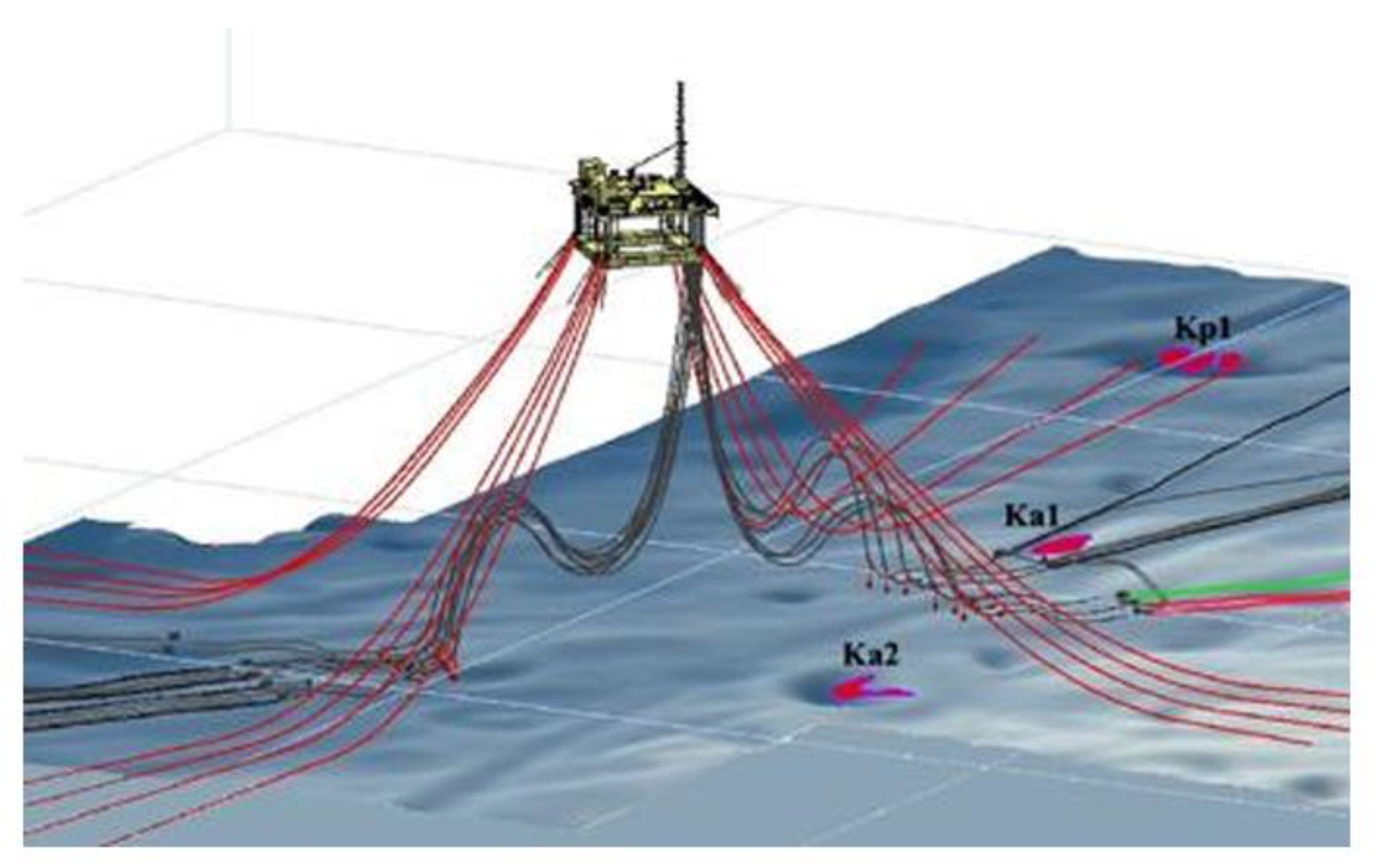
The Kristin field is also located offshore Mid-Norway, at water depths between 310 and 385 m, where we suspected that there could be abundant coral reefs, prior to our field mapping campaign. The oil in the reservoir at Kristin was hotter than usual, so they had to cool the oil before taking it on board the floating production platform (Figure 1). It was necessary to install some flowlines on the bottom, for cooling oil before it came to the platform. The floating Kristin platform was to be connected to the seafloor using four large suction anchors. Thus, the Kristin field, with numerous infrastructure elements on the seafloor, was a challenge for the planners and the construction department [4,5].
“During the detailed mapping period, it became clear that the location contains numerous large pockmark craters, and curiously, pockmark-dwelling coral reefs. This was surely not expected, as it was reckoned that corals settled on high ground, rather than inside depressions. The up-to-3.5 m high coral reefs were actually living some metres below the general seafloor level, inside the pockmark craters. After mapping, it turned out that within the 14 sq. km area of the total Kristin field, there is a medium density of pockmarks of about six per sq. km. They are typically 130 m wide and 10 – 12 m deep.
There was a total of 120 coral reefs. A quarter of these (33 reefs) occur inside or along the inside rim of pockmarks. Most of the other reefs are located within 200 m of a pockmark. The largest reefs at Kristin are up to 3.5 m high and 90 m in length.” [4].
To make sure that Statoil installed and maintained the complex infrastructure at Kristin in the best possible sustainable manner, we selected a total of three coral reefs for further detailed mapping and monitoring: “As part of the seafloor documentation prior to development of the Kristin field, three of the pockmark-dwelling coral reefs were surveyed visually, in July 2003 (pre-construction) and again in November 2006. None of the reefs had been damaged during the field development and initial production phase (i.e., post May 2006), as anchor patterns and flowline routes had been chosen such that they avoided the reefs.
The three inspected reefs are designated KP1, KA1, and KA2 (Figure 1). The size of the reefs, their depth span, and size of their associated pockmarks were measured. Because detailed mapping of the seafloor was performed with ROV-mounted multibeam echosounders and side-scan sonar, the exact locations and extents of the coral reefs are well documented.” [4].
3.8. Coral Reefs at the Morvin Field
At the neighbouring Morvin field, there would also be some challenges for the development engineers, with regards to coral reefs and activity. This field is located about 20 km northwest of Kristin, and there is an abundance of medium sized reefs. The seafloor at Morvin has general water depths of between 315 and 340 m. The seafloor has been modified by drifting and grounded icebergs, which have rendered the seafloor marked by linear iceberg plough-marks [4]. Most of the coral reefs are located adjacent to some of the slopes caused by these marks, and, therefore, tend to make linear rows of reefs: “…they seem to grow in the direction of the incoming prevailing bottom current, running from the southwest.” [4].
The Morvin field is one which has been developed with fully fledged sub-sea installations, i.e., without surface platform installations. Prior to drilling the production wells, Statoil had to complete the top-hole drilling, where it is normal to dispose of the drilling debris in the water column. However, with so many coral reefs on the seafloor, it was necessary to monitor the debris plume during this initial drilling campaign, that lasted for several months. Furthermore, it was mandatory that Statoil reported progress to the government every morning. If the debris plume threatened some of the live coral reefs, drilling had to be halted until the danger of silting on live coral reefs was over. After this drilling was completed, there had only been two cases where the drilling had to be halted for a total of 10 hours. The post-drilling visual inspection of potentially affected coral reefs proved no damage or significant silting of any coral reefs. Although it was costly with continuous ROV monitoring of downstream coral thickets, it proved necessary as this was out of norm, and the other technological alternatives would be much more costly.
3.9. The Marine Archaeology of the ‘Jederinog’ Wreck
In Norwegian waters, any shipwreck older than a century, or artifacts thereof, are protected by law. It is, therefore, up to the archaeological institute in charge, to make sure the law is obeyed by all industrial and other parties wanting to utilize the seafloor. This is often done by making the industry or parties aware of any nearby wrecks that have been registered or newly discovered. [6,7,8].
During planning of the final shore-approach route for the already complex Haltenpipe project, it became evident that there were potential remnants of an old shipwreck, covering a rather large area of the Ramsøy fjord, near Smøla and Frøya islands off Mid-Norway (Trondheim): Thus, “On 16th October, 1760, the Russian ship (‘Jederinog’, i.e., Unicorn) had reached the island of Smøla when a storm destroyed its three masts, leaving her to drift helplessly in the dangerous waters of the Ramsøy fjord.” [6]. Immediately before this happened, a group of 12 men had left the ship because of the bad weather brewing.
As one may have guessed, this part of the Ramsøy fjord was also where Statoil had found a favourable land-approach route for their pipeline. Some of the remnants of the wreck of Jederinog and her cargo, consisting of anchors, cannons, and lead plates lay very close to the planned route. A conflict of interest seemed unavoidable, as Statoil were not ready to accept extra costs for fulfilling their pipeline. The dispute started with the Institute of Archaeology at the Norwegian University of Science and Technology of Trondheim, which was responsible for this part of Norway, claimed that remnants of the wreck could potentially be damaged by Statoil’s offshore activities in Ramsøy fjord. Statoil did not want to cover extra costs at this stage of the project, if not totally necessary. After all, they had already constructed four major offshore pipelines, totalling up to 5000 kilometres of pipe, without having to bother about old shipwrecks and artifacts.
It has to be noticed, however, that Statoil had built part of their pipes onshore, and, like other operators, accepted as routine that archaeological investigations needed to be done prior to release of acreage for the land-pipe sections: “The latest edition of the law concerning marine objects was made in 1978 and clearly states that before construction work is carried out marine investigations must be done by the proper authorities. It also states that the owner of the construction is responsible for the costs of the investigations.” [6].
During several meetings with the authorities, Statoil were very reluctant to take the claim by the Institute of Archaeology seriously, and they considered two options: either ignore the claim, and await a lawsuit. The other option was to cooperate with the Institute and pay the extra expenses. They did not take long to agree on this latter option. “Thus, a marine archaeological survey was financed by Statoil in 1994 and carried out jointly by the Institute of Archaeology and the Department of Marine Systems Design. The project had two goals: 1) To investigate the shallow part of the site containing some of the ship’s cargo and cannons. 2) To investigate the deep area close to the pipeline track to locate the remaining parts of the hull and cargo. Parts are scattered over a large area, ranging from 50 to 280 m water depth.” [6].
For Statoil, my own experience with subsea research helped to stimulate inhouse interest in Marine Archaeological academic questions and viewpoints, so that the Haltenpipe project could use this project for their own local esteem in Mid-Norway. [8]. Thus, there is a win-win situation when an experienced “inhouse engineer who is able and willing to follow up the work performed by the institution. Without such a resource on Statoil’s side, the expenditure is mainly for the benefit of the receiver, and an opportunity for Statoil to gain experience and first-hand knowledge is lost.” [6]. One of the benefits is to popularise the new knowledge gained, such that the company can use it partly as factual and interesting local historical facts for general local public relations in the area where the land portions of the pipe are constructed.
3.10. A Fatal Blow-Out Accident Instigated Work to Stop More Blowouts: Improvements Made After the ‘West Vanguard’ Blowout, 1985 – An Eye Opener
This example shows how tragedy may lead to operative improvements of great importance. On August 6, 1985, the exploration drilling platform, ‘West Vanguard’ was operating about 100 km offshore Mid-Norway at the Midgard field. Unfortunately, they unintentionally drilled through a relatively thin sand-layer at a water depth of about 240 m. Because the drilling team were unaware of the possibility of drilling into sand, they misinterpreted the situation, so that gas filled the drilling string and found its way up to the drilling deck, where it expanded forcefully and caused severe damage. Unfortunately, one person was thrust off the drilling deck by the pressure wave and was lost overboard, presumed killed. The rest of the workers were successfully evacuated from the floating platform [9].
This accident was so severe, that two independent investigations were implemented to find out why and how it happened. Statoil formed an inhouse taskforce of 6 specialists to find out how to hinder a similar accident in the future. The Norwegian Government also initiated an independent investigation. The findings of this latter investigation was reported one year later and it proved that part of the blame was on Statoil’s personnel [10].
The gas zones had been difficult to detect accurately because of:
- 1)
- Unexpected high formation pressure
The West Vanguard was drilling in an area where shallow gas was present. However, there was inadequate awareness of the potential risks from these shallow gas zones, which on seismic sections were interpreted as negligible. However, the formation pressure in the shallow section turned out to be much higher than expected, which contributed to the well’s instability.
- 2)
- Inadequate geological survey and data interpretation
The governmental investigation report notes that the methods used to evaluate the presence of shallow gas were not adequate. The data resolution was not high enough. While there were some indications of shallow gas, these signals were not fully appreciated or understood by the crew. As a result, when drilling into the gas-bearing sand formation, the well was not sufficiently prepared to handle the large influx of gas that occurred [11].
- 3)
- Lack of shallow gas precautionary measures
Given the geological conditions and the high risk of shallow gas in the area, the well should have been drilled with greater caution. The investigation suggested that additional precautionary measures could have been implemented, such as adjusting the mud weight or using more advanced well monitoring tools.
One of the main contributing factors of the blowout was insufficient detection and preparation for shallow gas. At that time, the awareness of shallow gas risks was not as advanced as it is today. The West Vanguard blowout served as a wake-up call for the whole industry, that highlighted the importance of:
- -
- High-resolution surveys for detecting gas in shallow sediments
- -
- The monitoring of gas kicks in real time
- -
- Specialized well control practices for shallow gas zones.
Because they had full support inhouse and could use all resources they needed, the new Shallow Gas Group in Statoil, came up with some new and revolutionary methods for interpreting both 2D and 3D seismic data so that it facilitated the recognition of even small volumes of dangerous shallow gas. Thus, [12] and [11] explain some of the techniques that had been developed inhouse, and which had been shared by Statoil to other operators, after they had verified the technique on 150 wells, by 1995: “The technique of using exploration 3D seismic data for detection of shallow gas was pioneered by Statoil during the inhouse shallow gas project lasting from 1986 to 1989 (Gallagher et al., 1989, 1991). Shallow gas evaluations based on 3D data has since been a standard procedure in Statoil.
The most significant aspect of using 3D data to map drilling hazards is the use of horizontal displays (timeslices and attribute maps) leading to a better understanding of shallow gas settings and greater reliability of predictions which since implemented has had an accuracy close to 100%. Cost savings by reducing the site survey programmes are significant. In addition, considerable amounts are saved in the drilling operations due to the accuracy of the predictions which has a direct impact on well planning.” [11].
In response to the West Vanguard blowout, there was a heightened focus on improving the detection and management of shallow gas in offshore drilling operations. More advanced techniques for shallow gas detection were developed, and new regulations were put in place requiring companies to take additional precautions when drilling in areas with suspected shallow gas.
This case helped shape the development of modern drilling techniques and safety measures in Norway and Worldwide.
4. Conclusions
As can be seen from the results presented in this article, for me, personally, there has been practical and mental inspiration throughout most of the projects and challenges. This is mainly thanks to good leadership, where my leaders trusted me as a senior engineer and part academic. Throughout, I have been able to publish many of the results and surprising observations in the deep ocean. The period starting with Ekofisk in 1970, until my retirement, in 2014, after serving both with Statoil (now Equinor), from 1976 to 2012, and Shell (2012-2014), has certainly been a more-or-less continuous period of technological development and improvements in how we handle and develop subsea space.
My main conclusion is that sustainable development of large offshore technological projects can only be guaranteed by good leadership, competent and experienced personnel, cooperation with governmental agencies, and full transparency. In Norway, we have enabled such work systems on a broad scale.
The Norwegian offshore oil and gas industry, including the general marine deep-water industry (shipping and sub-sea instrumentation) has been developing to greatly improve our ability to complete complex technological projects in extreme environments in a guaranteed sustainable manner.
Funding
This research received no external funding.
Data Availability Statement
All data used herein is already published and available on the web.
Acknowledgments
I thank Hans Konrad Johnsen for helping me with certain aspects of the article.
Conflicts of Interest
The author declares no conflicts of interest.
Abbreviations
The following abbreviations are used in this manuscript:
| NCS | Norwegian Continental Shelf |
| NPD | Norwegian Petroleum Directorate |
| IKU | Institutt for Kontinentalundersøkelser |
| STSP | Stafjord Transportation System Project |
| WW | World War |
| ROV | Remotely operated vehicle |
References
- www.Equinor.industriminne.no/statpipe-en-bragd/(2025).
- Norwegian Government, 2025: Recommendation from the reinforced industry committee on prospecting for and recovering submarine natural resources on the Norwegian continental shelf (Recommendation no 294 (1970-71) to the Storting, 7 June 1971.
- King, L.H. MacLean, B. Pockmarks on the Scotian Shelf. Geological Soc. America Bulletin. 1970, 81, 3141–3148. [Google Scholar] [CrossRef]
- Hovland, M. , 2008. Deep-water coral reefs: Unique biodiversity hotspots. Springer Praxis, 278 pp.
- Elliott, C. 2025. As Norway considers deep-sea mining, a rich history of ocean conservation decisions may inform how the country acts. www.Smithsonianmag.com/science.nature/as-norway-considers-deep-sea-mining-a-rich-history-of-ocean-conservation-decisions-may-inform-how-the-country-acts-180986412.
- Hovland, M. , Jasinski, M.E., Søreide, F. How solving conflict saved old shipwreck. Norwegian Oil Review 1998, 7, 98–102. [Google Scholar]
- Hovland, M. , 2005. Pockmark-associated coral reefs at the Kristin field off Mid-Norway. In: Freiwald, A., Roberts, J.M. (eds). Cold-Water corals and ecosystems. Springer Verlag, Berlin, pp 623-632.
- Jasinski, M.E. The Unicorn – About a dramatic wrecking and a marine archaeological investigation (in Norwegian). Spor # 1994, 2, 36–40. [Google Scholar]
- Hovland, M. , Judd, A.G., 1988. Seabed pockmarks and seepages. Graham & Trotman, London, 239 pp.
- Norwegian Petroleum Directorate report. NPD, 1986.
- Heggland, R, Nygaard, E., Gallagher, J.W., 1996. Techniques and experience using exploration 3D seismic data to map drilling hazards. Offshore Technology Conference (OTC), paper # 7968.
- Gallagher, J.W. , Braaten, A.M., Hovland, M., Kemp, A.C., 1989. Use of an Interpretation Station for the study of shallow gas sands on Haltenbanken. Paper at 1989 NPF Conference, Stavanger, April 10-11.
Figure 1.
The Kristin floating platform and its seafloor infrastructure, consisting of flowlines and anchor wires. Three pockmark-dwelling coral reefs Ka2, Ka1, and Kp1 are shown in red. They have been monitored with regular intervals, and, also, before and after field development. There has been no harm done to them, that can be visually documented. Modified from [4].
Disclaimer/Publisher’s Note: The statements, opinions and data contained in all publications are solely those of the individual author(s) and contributor(s) and not of MDPI and/or the editor(s). MDPI and/or the editor(s) disclaim responsibility for any injury to people or property resulting from any ideas, methods, instructions or products referred to in the content. |
© 2025 by the authors. Licensee MDPI, Basel, Switzerland. This article is an open access article distributed under the terms and conditions of the Creative Commons Attribution (CC BY) license (http://creativecommons.org/licenses/by/4.0/).
Copyright: This open access article is published under a Creative Commons CC BY 4.0 license, which permit the free download, distribution, and reuse, provided that the author and preprint are cited in any reuse.


