
Submitted:
17 November 2025
Posted:
18 November 2025
You are already at the latest version
Abstract
This study investigates the feasibility of using waste heat from generator sets as the low-temperature heat source for heat pumps in off-grid energy systems, addressing the need for more efficient and self-sufficient heating solutions. A conceptual model was developed in which a generator and an air-to-water heat pump operate within an insulated thermal chamber, enabling the recovery of waste heat to maintain a stable 15°C inlet temperature for the heat pump. Theoretical analysis was supplemented with preliminary experimental tests performed on a small generator placed in a thermally insulated enclosure. Measurements of temperature rise and heat output allowed verification of the real heat-recovery efficiency, which reached approximately 28%. Based on real household heating demand, the study evaluated annual heat demand, heat pump electricity consumption, and fuel requirements for several recovery scenarios (28%, 45%, and 60%). The results show that maintaining a constant 15°C source temperature significantly improves heat-pump efficiency, reducing annual electricity demand. Increasing heat-recovery efficiency from 28% to 60% reduces fuel consumption by more than half and lowers annual operating costs. The findings confirm the potential of generator-supported heat-pump systems to enhance energy efficiency in off-grid applications and provide a sound basis for further optimization and real-scale validation.
Keywords:
waste heat recovery
; off-grid energy system
; heat pump
; power generator
1. Introduction
In the face of increasing demand for sustainable energy sources and the necessity to reduce greenhouse gas emissions [1], hybrid systems that integrate different technologies to improve overall energy efficiency are gaining in popularity [2,3]. In particular, in off-grid areas where access to the power grid is limited or non-existent, it becomes crucial to develop solutions that can ensure energy independence [4,5,6]. In such systems, generator sets can provide both electrical power and heat. The heat in this configuration is recovered and reused waste heat [7].
In typical generator sets based on internal combustion engines, only 30-40% of the energy contained in the fuel is converted into useful mechanical work, while 60-70% is lost as waste heat [8,9,10]. This means that a significant portion of the supplied energy remains unused, leading to substantial energy losses [11,12,13]. In practice, waste heat originates mainly from the exhaust system and the engine cooling systems, which are traditionally not designed with heat recovery in mind. However, by using heat exchangers and modern technologies such as heat pumps or thermodynamic cycles (e.g. the Rankine cycle), this heat can be converted into useful energy, which significantly increases the overall efficiency of the system [14,15,16,17,18]. Figure 1 shows an example thermographic image, where it can be observed that engine components heat up to high temperatures, confirming that a large share of the energy in generator sets is lost in the form of waste heat.
The use of a heat pump as the low-temperature heat source in hybrid systems incorporating generator sets offers significant potential. Heat pumps are known for their high efficiency, particularly when the low-temperature source provides stable thermal conditions. Waste heat from a generator originating from the exhaust system and engine cooling circuits, constitutes an excellent low-temperature heat source that can significantly increase the overall efficiency of the heating system. Studies indicate that integrating a heat pump powered by generator waste heat can improve the energy efficiency of the system by 20-30% compared with conventional solutions [19].
One of the key challenges associated with waste-heat recovery in hybrid systems is the optimal utilization of available energy, especially in off-grid conditions where balanced management of energy resources is crucial. Off-grid systems operate independently from external energy suppliers, making waste-heat recovery a potentially critical component for maintaining high energy efficiency. In such systems, waste-heat recovery not only increases performance but also reduces the demand for fossil fuels, which directly translates into lower greenhouse gas emissions. According to research [20], implementing waste-heat recovery in internal combustion engines and generator sets can lead to a reduction in CO₂ emissions of up to 15-20%, which is particularly important in the context of global climate-protection commitments [21].
Moreover, advancements in energy-storage technologies (such as lithium-ion batteries and supercapacitor-based storage systems) enable even more efficient energy management in hybrid configurations [22,23,24]. Energy storage allows surplus electricity generated by the generator set during periods of lower demand to be stored and used later. This strategy enhances the stability and independence of off-grid systems while simultaneously minimizing energy losses [10].
The development of a hybrid energy system that integrates generator sets with heat pumps and waste-heat recovery technologies represents not only an attractive approach for sustainable development but also a practical step toward improving overall energy efficiency. The aim of this study is to analyze the performance of a hybrid system in which a generator set produces electrical power for ongoing energy needs, while waste heat from the generator is used as the low-temperature heat source for a heat pump. In this context, a detailed assessment of the energy efficiency and potential savings resulting from waste-heat recovery in off-grid systems will be carried out.
2. Materials and Methods
This chapter presents the concept of a system in which a generator set supplies electrical energy to a heat pump, while the waste heat produced by the generator is simultaneously utilized as the low-temperature heat source within a specially designed thermal chamber. The system is intended to enhance the efficiency of the heat pump by increasing the temperature inside the thermal chamber, which raises the heat pump’s coefficient of performance (COP). As a result, the heat pump requires less electrical energy to generate a unit of heat at the upper heat source. An additional objective of the system is to achieve partial or full energy independence from external sources of both thermal and electrical energy.
Figure 2 presents the block diagram of the conceptual thermal-chamber system integrating the generator set and the heat pump.
The thermal chamber, being the key element of the system, should be designed to accommodate both the outdoor unit of the air-to-water heat pump and the generator set. Its dimensions must ensure sufficient space for proper installation of the equipment as well as for any required maintenance activities. The chamber should be constructed from materials with high thermal insulation properties to minimize heat losses and high acoustic insulation to reduce noise generated by the generator.
The air required for the generator engine should be supplied from outside the chamber through a thermally insulated duct equipped with an air filter. Exhaust gases should be routed outside the chamber through a duct made of a material with good thermal conductivity, allowing part of the exhaust heat to be transferred into the chamber. Outside the thermal chamber, the exhaust duct should be acoustically insulated to minimize noise emissions to the surroundings.
The selection of the generator set should be based on an analysis of the annual heating demand and the catalogue data of the heat pump, taking into account the so-called bivalent point [25]. The bivalent point defines the outdoor temperature at which the heat pump can independently cover the building’s heating demand [26,27]. The generator should supply sufficient electrical power to operate the heat pump throughout the entire year, ensuring stable operation even at the lowest expected outdoor temperatures, when the performance of a traditional heat-pump system typically decreases. Therefore, the generator must be sized so that its maximum electrical output slightly exceeds the heat pump’s power demand at the lowest assumed air temperature inside the thermal chamber, providing a safety margin against efficiency reduction.
It should be noted that in this configuration, the bivalent point depends not on the outdoor air temperature (since the heat pump uses air drawn primarily from inside the thermal chamber, and only from the outdoor environment in emergency situations such as generator failure), but on the temperature that is maintained inside the insulated chamber. This temperature can be regulated by an external-air damper. By mixing cold outside air with the hot air produced by the generator, the system can maintain the chamber temperature within a defined range, enabling the heat pump to operate with the highest possible COP.
To monitor and control the thermal conditions inside the chamber, temperature sensors should be installed in strategic locations. These sensors will enable automatic regulation of the generator set and the heat pump, responding to temperature variations and maintaining optimal conditions within the thermal chamber. The generator should start under two circumstances: first, when electrical power is required to supply the heat pump, and second, when the temperature inside the chamber drops below a predetermined threshold. This operating strategy ensures a continuous increase in the chamber’s air temperature, directly improving the heat pump’s COP and enhancing its overall energy efficiency.
For safety reasons, the fuel tank for the generator set should be located outside the chamber, which reduces the risk of fuel vapor accumulation and limits the need to open the chamber, thereby minimizing thermal losses. The entire system should be designed so that the waste heat from the generator (serving as the heat pump’s low-temperature heat source) is effectively utilized to warm the air inside the chamber. This approach allows the heat pump to operate with higher efficiency compared with conventional configurations.
Figure 3 presents the schematic diagram of the thermal-chamber system integrating the generator set and the heat pump.
If the generator produces more electrical energy than is required for the current operation of the heat pump, the surplus can be stored in an external electrical energy storage system or redirected to supply, for example, a domestic hot water tank, where it can be converted into heat using an electric heater. Although this aspect is not the focus of detailed analysis at this stage of the work, it will be addressed in future studies. Such an approach could potentially enable the development of a single-family building that is almost completely energy independent (with the exception of the energy derived from fuel combustion).
Ultimately, the entire system should be designed to maximize resource utilization by generating both heat and electrical energy while minimizing waste-heat losses. This allows for a reduction in operating costs and a decrease in environmental impact through optimal management of energy and recovered waste heat.
3. Results
In this study, a theoretical model of the system’s operation is presented, complemented by an experimental component that enabled empirical verification of the assumed performance parameters of the generator set under controlled conditions, including generator output, the amount of waste heat produced, and the rate of thermal-chamber heating.
3.1. Theoretical Introduction
To calculate the thermal power generated by the generator set, the first step is to determine its electrical power output (Pel). Next, the electrical generation efficiency (Pel l) must be assumed, which for small generator sets typically amounts to approximately 30%. The maximum thermal power (Pheat max) produced by the generator, according to Sankey diagram assumptions, is approximately 60% of the total input power [28,29]. However, after accounting for additional losses of around 5%, which may result from mechanical losses, manufacturing tolerances of generator components, or mechanical wear, this share can be estimated at about 55%. Based on these assumptions, the thermal power of the generator can be calculated using the following formula:
- where:
- Pel – electrical output power, kW
- Pel – efficiency of converting fuel energy into electrical energy, %.
The thermal power (P(t)) generated at time (t) can be calculated using an equation that incorporates the system’s time constant:
- where:
- Pheat – thermal power, kW,
- Pheat max – maximum thermal power, kW,
- t – operating time of the generator, s,
- τ – time constant of the thermal system, s,
- e – base of the natural logarithm.
The time constant results from the heat-transfer equation and can be determined from the following formula:
- where:
- C – thermal capacity of the system (dependent on the mass and specific heat capacity of the materials forming the generator), J/K,
- R – thermal resistance (dependent on the effectiveness of heat transfer between the system and the surroundings), K/W.
The final result of integrating equation (2) over the interval from t1 to t2:
A generator set placed inside a closed chamber produces thermal energy during operation, which leads to an increase in the chamber’s internal temperature. At this stage of the analysis, it is assumed that heat losses to the surroundings have been indirectly accounted for by applying a corrected thermal power value for the generator, reduced by 5%. Including heat losses within the calculated power values allows the thermodynamic model to be simplified by assuming that the net thermal energy introduced into the chamber by the generator corresponds to its effective thermal output.
For further calculations, the thermal power (P) transferred to the air inside the chamber was determined using the following equation:
- where:
- P – heat power transferred to the air, equal to the heat power of the generator (Pheat), W,
- cp – specific heat of air at average temperature difference, J/kgK,
- ΔT – temperature difference in the chamber between the start and end of the measurement, K,
- t1, t2 – operating time of the unit, s,
- Vc – chamber volume, m3,
- ρ – air density at average temperature difference, kg/m³.
The temperature increase (ΔT) inside the chamber as a function of time, resulting from heating by the generator, can be calculated by rearranging the thermal-power equation of the system into the following simplified form:
Taking into account the fact that the heat pump extracts heat from the chamber, this process contributes to a reduction in the chamber temperature over time. The final equation describing the temperature change inside the chamber, incorporating both the thermal power generated by the generator and the heat extracted by the heat pump at a given coefficient of performance (COP), can be expressed as follows:
- where:
- Php - heat pump heating power, W,
- COP – heat pump heating efficiency coefficient, -.
It should be noted that the second term in equation (4) essentially represents the thermal power of the low-temperature heat source (PDHS(t)). The heating capacity of the heat pump and the corresponding COP values are typically provided in the manufacturer’s technical documentation, and these parameters depend primarily on the temperatures of the low-temperature and high-temperature heat sources. In the analysed case, the temperature of the upper heat source is constant at 35°C for space heating and 55°C for domestic hot water production; therefore, these values depend solely on the temperature prevailing inside the thermal chamber.
The next step in the analysis is to determine the unit cost of energy obtained from fuel combustion in the generator set in order to assess the cost of producing 1 kWh of heat within the analysed system. The cost of generating 1 kWh of electrical energy by the generator can be calculated based on the amount of produced energy and the corresponding fuel consumption, using the following equation:
- where:
- C – cost of generating 1 kWh of electricity, kWh,
- Pel – amount of electricity generated by the generator, kWh,
- Fc – fuel consumption, l/h,
- Fp – fuel price, €/l.
The results of the simulation and the obtained outcomes are presented in the following sections of this work.
3.2. Preliminary Experimental Verification
As part of the experimental stage, the generator set with parameters listed in Table 1 was placed inside a thermally insulated chamber equipped with an air supply duct for the engine and an exhaust-gas removal system. The chamber insulation was constructed using mineral wool placed between two layers of steel-clad composite panels, providing an overall thermal efficiency of approximately 95% for a temperature difference of 60 K (−20°C outside and +40°C inside the chamber). The chamber dimensions were 1.5×1.2×1.2 m, resulting in a total internal volume of 2.16 m³.
Inside the chamber, Pt1000 resistance temperature sensors were installed within the working space to ensure accurate measurements of temperature distribution and temporal changes during generator operation, as well as to monitor the temperature outside the chamber. A 2000 W electric heater was connected as the electrical load for the generator. The layout of the experimental setup is shown in Figure 4.
The purpose of this stage was to determine the distribution of electrical power and thermal power generated by the generator set. Electrical energy was measured using an electricity consumption meter, whereas the amount of thermal energy was determined based on the temperature increase inside the insulated thermal chamber. At this stage, the heat pump itself was not included in the verification process.
During the experimental investigation, the air temperature inside the thermal chamber was measured at the beginning and at the end of the generator’s operation, which enabled the determination of the temperature increase ΔT and, consequently, the calculation of the thermal power generated by the unit. The initial air temperature inside the chamber was 20°C. The measurements were continued until the internal temperature reached 50°C. This temperature is fully sufficient to supply the heat pump’s low-temperature heat source for the production of heat at temperatures exceeding 50°C. The decision to limit the temperature was also motivated by safety considerations, particularly the risk of gasoline vapour ignition in the generator’s fuel tank at elevated temperatures.
The exhaust gases were discharged outside the chamber through a flexible stainless-steel flue duct. A portion of the exhaust heat was transferred directly into the chamber through the duct walls, contributing to the overall heat gain within the enclosed space. The experimental setup is presented in Figure 5.
Based on the measured temperature values and the corresponding operating time, the actual thermal power transferred to the air inside the chamber was determined. These results were compared with the electrical power generated by the generator set, allowing an assessment of its combined thermal-electrical performance. This comparison makes it possible to relate the obtained experimental values to the theoretical Sankey distribution for an internal combustion engine, the reference values of which are presented in Table 2.
It should be emphasized, however, that these considerations are of a theoretical nature. The experimental tests were not carried out under rigorous laboratory conditions but served as a preliminary verification of the underlying assumptions. Therefore, the results should be regarded as indicative, providing a useful basis for further and more detailed analyses.
Figure 6 presents the measured temperature profile and the corresponding thermal power recovered inside the chamber, originating from the generator set, for the analysed thermal enclosure with a volume of 2.16 m³.
The energy balance of the device can be expressed as follows. First, the theoretical heat losses associated with the exhaust gases, the engine block, and the mechanical losses manifesting primarily as friction-related heat, must be summed. The total value of these losses equals 4665 W. If the electrical output power of the generator is 2000 W, this corresponds to a required fuel input power of approximately 6665 W. Therefore, the theoretical efficiency derived from the Sankey-type distribution of energy in the generator set is 2 000 W / 6 665 W, i.e., approximately 30.0%.
The initial slow rise in temperature and thermal output was caused by the need to heat up the cold structural surfaces of both the chamber and the generator itself. After approximately 80 seconds, the rate of heat increase became limited by the thermal capacity of the chamber. As shown in Fig. 6, the temperature begins to asymptotically approach a steady-state value, at which the balance between the heat supplied and the heat dissipated (including losses through the chamber walls) is reached. The tests were conducted under constrained experimental conditions, which do not fully represent the actual energy performance of the generator set. In the closed thermal chamber with a volume of 2.16 m³ and for a relatively short operating period of 270 seconds, the maximum recorded thermal output was 1 856 W. This value indicates a significantly lower efficiency of converting the fuel’s chemical energy into usable heat compared with the theoretical 30% assigned to engine heat losses and the additional 30% associated with exhaust gases in the Sankey model.
This discrepancy is justified, as only a fraction of the thermal energy contained in the high-temperature exhaust gases was able to transfer through the walls of the exhaust duct into the chamber within such a short exposure time. A more effective exhaust heat recovery design would therefore be required, for example, by integrating extended surface heat exchangers (finned structures) or by replacing natural convection with forced convection to increase heat transfer. Furthermore, the system likely did not reach full thermal stabilization, as the measurement was intentionally stopped once the target internal temperature of 50°C was reached. At the beginning of operation, a considerable portion of the generated thermal energy is absorbed by the generator’s own components, such as the housing, cooling system, piping, and exhaust system. These components possess their own heat capacity, and heating them requires time. Only after they reach a higher temperature does heat begin to transfer more effectively to the surrounding air inside the chamber.
If the measurement is interrupted too early, the generator may still be in its warm-up phase, meaning that a significant portion of the produced heat has not yet transferred to the air. The experimental results therefore indicate an effective thermal recovery efficiency of approximately 28%, rather than the 60% predicted by the theoretical Sankey model. Assuming the validity of the Sankey distribution, the experimental setup suggests that as much as 32% of the total thermal energy may have been lost through mechanisms such as incomplete recovery of exhaust heat and heat conduction through the chamber structure—representing the difference between the theoretical 60% and the measured 28%.
The discrepancy arises from several factors, such as excessive heat losses to the surroundings, the relatively slow heating of the generator, and an insufficient contribution of exhaust-gas heat to the chamber’s overall heat balance. Despite these differences, the key assumption has been confirmed, namely, that it is possible to achieve a high chamber temperature, which should allow the heat pump to operate with a high COP.
The obtained results are very useful, as they define the next steps required to significantly improve the performance of the proposed system consisting of a heat pump and a generator set enclosed in a thermal chamber. To increase the heat recovery ratio in future studies, it is planned, among other measures, to reduce heat losses to the environment by improving the insulation and sealing of the chamber, to increase the contribution of exhaust-gas heat by implementing a more efficient exhaust heat exchanger, and to enhance the distribution of hot air inside the chamber by using a small circulation fan.
3.3. Analysis of the Operation of the Heat Pump and Generator Set
In this section, based on real operational data from a heat pump installed in a single-family house with a floor area of 136 m², a heating demand of 6 kW, and occupied by two adults, an analysis was carried out of the thermal energy consumption for space heating, domestic hot water (DHW) preparation, and the total electrical energy consumption of a 7 kW heat pump. The heat pump was selected in accordance with the manufacturer’s guidelines based on the bivalent temperature. The building is equipped with a low-temperature underfloor heating system for space-heating purposes, while DHW is supplied by a 200-litre storage tank.
The heat pump supplies two main heating circuits. The first circuit covers space heating (SH) via underfloor heating, for which the required supply temperature is 35 °C. The second circuit is responsible for DHW preparation and requires a higher supply temperature of 55 °C. The difference in required temperatures between these circuits has a direct impact on the heat pump’s coefficient of performance (COP).
The outdoor unit of the heat pump is intended to be installed inside the thermal chamber together with the generator set, which will serve a dual function: generating electrical energy for the heat pump and household appliances, and providing waste heat to warm the air inside the chamber. The temperature inside the thermal chamber will be maintained at a minimum of 15 °C, instead of the previously tested 50 °C. Maintaining such a temperature enables the heat pump to operate with a high COP while simultaneously reducing the risk of overheating critical components, thereby lowering mechanical wear and maintenance frequency. Furthermore, operating the heat pump with a significantly higher heat-source temperature would require a continuous supply of large amounts of waste heat from the generator. Such a condition can only be sustained during high generator loads, which would result in excessive overproduction of electrical energy—uneconomical if the household does not have sufficient electrical demand.
By maintaining a temperature of 15 °C in the thermal chamber during the heating season, the system operates both efficiently and economically, while also extending the service life of its components. During the summer and transitional periods, outdoor air temperatures exceed 15 °C; therefore, the heat pump will extract heat directly from outside air rather than from the chamber, which also ensures a high COP.
Figure 7 presents the COP characteristics of the heat pump for the space-heating and DHW circuits at different outdoor temperatures.
This plot illustrates the variation in heat pump performance as a function of the operating temperature. For the lower supply temperature required by the space-heating system (35 °C), the COP is higher, indicating more efficient energy use. Conversely, for the higher temperature required for domestic hot water preparation (55 °C), the COP is lower due to the increased energy demand. For the subsequent analyses, the relevant COP values are those corresponding to the average temperatures during the summer and transitional periods, as well as those for the heating season, assuming a heat-source temperature not lower than 15 °C. These values were approximated from the manufacturer’s performance chart. For example, during the heating season, the COP is approximately 6 for space heating (SH) at the operating point A15/W35, and approximately 3.5 for domestic hot water (DHW) production at the operating point A15/W55. Analogous COP values were determined for the summer period.
The daily amount of required heating capacity for domestic hot water preparation was calculated using the following formula:
- where:
- PDHW – required heating capacity for DHW preparation, kW
- V – water tank capacity, 200 dm3
- cw – specific heat of water, 4,2 kJ/kgK
- ρ – water density for average water temperatures between 10°C and 55°C, 995,3 kg/m3
- τw – time required to heat water in the tank, 2h
- ΔT – the difference in temperature between cold and hot water, 45K
The time required to heat the water in the storage tank, τw, was assumed to be 2 hours, with two heating cycles per day: at 5:00 in the morning and at 20:00 in the evening. Therefore, for the purpose of calculating the heating capacity of the heat pump for domestic hot water (DHW) preparation, a value of 5.24 kW operating for 2 hours per day should be used. During this period, the heat pump does not supply heat to the space-heating system during the heating season, as DHW production has priority.
Table 3 presents the monthly data related to the domestic hot water heating system.
The annual heat demand for domestic hot water preparation amounts to 3,825 kWh.
In the case of space heating, the heat demand depends significantly on the outdoor temperature. The relationship below defines this dependence based on the maximum heating demand of 6 kW, as previously assumed, at the design outdoor temperature of 20°C for the selected location (Podkarpackie region, Poland). By introducing an additional boundary condition that marks the end of the heating season at an outdoor temperature of 16°C, the heat demand as a function of outdoor temperature can be expressed as follows:
- where:
- PCH(Tout) – heat demand for heating purposes, kW
- Tout – outside temperature, °C
In Table 4, the data related to the heat supply system for space heating are presented.
The seasonal heat demand during the heating period (from October to April) for space heating (CH) is 11,045 kWh. Outside the heating season (from May to September), the heat pump does not produce heat for space heating and operates solely to meet the demand for domestic hot water (DHW).
The analysis of these results makes it possible to assess the seasonal energy consumption and the operating costs of the heat pump, providing a basis for optimizing the operation of the system depending on the current demand for space heating and domestic hot water in the building.
For the correct selection of a generator set that will supply only the heat pump with a heating capacity of 7 kW, a traditional approach would require considering the electrical power demand of the heat pump under the most challenging outdoor conditions, i.e., at the bivalent temperature of -11°C. In the proposed solution, however, the heat pump should be sized according to the temperature of the low-temperature heat source, which is assumed to be 15°C inside the thermal chamber.
The coefficient of performance (COP) of the heat pump at the operating point A15/W55 (i.e., 15°C heat source and 55°C heat sink temperature for DHW production) is COP = 3.5. The COP at the operating point A15/W35 (i.e., 15°C heat source and 35°C heat sink temperature for CH) is COP = 6.
This means that in order to generate 6 kW of heating power for space heating or 5.24 kW for domestic hot water, the heat pump consumes 1 kW of electrical power for CH and 1.50 kW for DHW. It also follows that the heat pump must extract 5 kW of heat from the low-temperature source for CH, and 3.74 kW for DHW.
Considering only the heat pump’s electrical power demand, and in order to ensure stable operation of the generator while minimizing overload risk, a safety margin should be applied; therefore, the electrical power of the generator should be no less than approx. 2.0 kW. In case of excess generated electrical energy, the surplus may be stored in a battery system or used to cover domestic electrical loads. If the generator cannot supply the required electrical power, the system should allow the heat pump to be powered from the energy storage unit, ensuring uninterrupted operation, or alternatively from the electrical grid.
The heat generated by the generator (treated as waste heat) will be used to warm the thermal chamber housing the outdoor unit of the heat pump. In this manner, it will serve as the heat pump’s low-temperature heat source, ensuring stable operating conditions. Based on the measurements, approximately 28% of the energy produced by the generator can be recovered as heat originating from both engine thermal losses and a portion of the exhaust heat. Assuming an electrical efficiency of 30%, this means that 30% of the fuel energy becomes electrical output, while the remaining 42% constitutes unrecovered losses.
This represents a significant heat loss when compared with Sankey-based theoretical distributions, where up to 60% of the fuel energy should be recoverable, and only about 10% constitutes losses. Therefore, further calculations in this work consider three operating variants. Variant I reflects the experimentally obtained waste heat recovery efficiency of 28%. Variant II assumes an intermediate recovery efficiency of 45%, which may be realistically achievable after several improvements, such as enhanced thermal insulation of the chamber or a more efficient exhaust heat exchanger. Variant III corresponds to the theoretical Sankey assumptions, with a 60% waste heat recovery rate.
Variants I-III are additionally compared with Variant 0, in which the heat pump operates conventionally, meaning it is powered directly from the electrical grid and extracts heat from outdoor air. Consequently, the COP depends on the ambient temperature.
Figure 8 presents the COP values for each analyzed variant.
Based on the heat demand for space heating and domestic hot water preparation, as well as the corresponding COP values, the electrical energy demand was determined for each analyzed variant. The results for the individual variants are presented in Table 5 and Table 6.
In each of the analyzed variants, the total annual heat demand remains the same at approximately 14 870 kWh, of which 11 046 kWh corresponds to space heating (CH) and 3 824 kWh to domestic hot water preparation (DHW). The differences between the variants relate to the consumption of electrical energy. In Variant 0, where the heat pump is powered by electricity from the grid and the temperature of the heat source depends directly on outdoor conditions, the total annual electricity consumption amounts to approximately 4,538 kWh (including 3 127 kWh for heating and 1 411 kWh for hot water preparation).
In Variants I–III, where the temperature of the low-temperature heat source is maintained at a constant 15°C using waste heat recovered from the generator set, the annual electricity consumption decreases to approximately 2 939 kWh (1 845 kWh for heating and 1 094 kWh for domestic hot water). This reduction results directly from the improved COP of the heat pump operating under stable thermal conditions.
Table 7 presents the input data used for further analysis in Variants I, II, and III. As mentioned earlier, these variants differ primarily in the efficiency of waste heat recovery from the generator set: Variant I assumes 28%, Variant II 45%, and Variant III 60%. The level of heat recovery directly determines the amount of electrical energy that the generator must produce, since the system’s priority is to supply sufficient heat to the thermal chamber to maintain the target temperature of 15°C. Consequently, in Variant I (characterized by the lowest recovery efficiency) the generator must operate longer or at a higher load to meet the thermal requirements of the chamber, resulting in higher fuel consumption compared to Variants II and III. These differences translate directly into the operating costs of the system, which are examined in detail in the subsequent part of the study.
The operating costs for Variant 0 result directly from the electricity consumption of the heat pump for space heating and domestic hot water preparation. An electricity price of 0.28 €/kWh was assumed for the analysis. Table 8 presents the annual operating costs for Variant 0.
The total cost of space heating and domestic hot water preparation in Variant 0 amounts to 1 271 €/year.
To calculate the fuel consumption for Variants I-III, it was assumed that 1 liter of diesel fuel provides 10 kWh of chemical energy [31,32]. The generator set converts part of this energy into electricity and part into waste heat, which in the analyzed system is utilized as the low-temperature heat source for the heat pump.
In the calculations, the electrical efficiency of the generator was assumed to be 30%, while the efficiency of waste heat recovery depends on the considered variant and amounts to 28% (Variant I), 45% (Variant II), and 60% (Variant III).
The total amount of heat that must be supplied to the heat pump’s low-temperature source during the heating season was determined based on the energy balance of the heat pump, as the difference between the total heat delivered by the pump and the electrical energy consumed by the compressor. Then, knowing the recovery efficiency, the chemical energy of the fuel required to deliver this amount of heat was calculated using the following relation:
- where:
- Qfuel – chemical energy of fuel, kWh,
- QL – heat from the lower heat source, kWh,
- ηrec – heat recovery efficiency from the unit, %.
The low-temperature heat (QL) represents the amount of energy that the heat pump must extract from the environment (or, in this case, from the generator set) in order to deliver the required thermal output for space heating and domestic hot water preparation. The value of QL depends on the coefficient of performance (COP) and can be expressed as:
- where:
- Qi – zapotrzebowanie na ciepło dla potrzeb centralnego ogrzewania (CH) lub ciepłej wody użytkowej (DHW), kWh.
Next, the amount of fuel consumed was determined using the following formula:
- where:
- FC – fuel consumption, l.
The obtained result was then multiplied by the unit price of the fuel (1.40 €/l), which made it possible to determine the operational cost of the generator set.
The fuel consumption for the non-heating season was calculated in an analogous manner; however, in this case, heat recovery is not required. During the summer period, the generator operates solely to produce electricity necessary to supply the heat pump during domestic hot water preparation.
Table 9 presents the results for variants I-III. The designation X-IV refers to the results for the heating season (October to April), while V-IX refers to the results for the summer season (May to September).
As the efficiency of waste-heat recovery increases, a clear decrease in fuel consumption is observed. For Variant I, with a recovery efficiency of 28%, the annual diesel consumption (FC total) amounts to 4 007 liters, whereas for Variant II (45%) it decreases to 2 551 liters, and for Variant III (60%) it is reduced further to 1 952 liters. This corresponds to annual fuel costs (Ctotal) of 5 610 €, 3 571 €, and 2 733 €, respectively. At the same time, the amount of electrical energy generated by the generator set decreases with increasing heat recovery efficiency. Over the entire year, the total electrical energy production (Eel total) equals 12 020 kWh, 7 652 kWh, and 5 854 kWh for Variants I, II, and III, respectively. The amount of surplus electrical energy (Eel +) is 9 086 kWh in Variant I, 4 719 kWh in Variant II, and 2 920 kWh in Variant III.
These results indicate that the surplus electrical energy may significantly exceed the typical annual electricity consumption in a household for powering electrical appliances such as consumer electronics, home appliances, and lighting, which for a four-person household typically amounts to 3 000-4 000 kWh/year [33,34]. In Variant III, the surplus energy is comparable to this demand; in Variant II, it should fully cover it with some reserve; whereas in Variant I, the surplus remains substantially higher. Detailed planning of how to utilize the excess energy— including the analysis of self-consumption strategies, the use of energy storage systems, and potential export of energy to the grid—lies beyond the scope of this study and will be the subject of future research.
The analysis of four operating variants of the system, a conventional configuration (Variant 0) and three configurations with waste-heat recovery (Variants I-III), revealed clear differences both in operating costs and in the overall energy performance of the system. Variant 0, in which the heat pump operates under traditional conditions and is supplied with electricity from the grid, is characterized by the lowest unit cost of energy but also by the highest electricity consumption, resulting from operation at variable and often low outdoor air temperatures.
The remaining variants are significantly more expensive to operate than the baseline Variant 0. In Variants I-III, the dominant cost factor is the fuel consumed by the generator set. However, it should be emphasized that these variants generate substantial amounts of surplus electrical energy, demonstrating that the system can cover not only the heat pump’s demand but also a considerable portion, and in some configurations even the entirety, of the household’s electrical consumption. On the other hand, this surplus requires appropriate management, for example through the use of energy storage systems, electric heaters for additional water heating, or control strategies aimed at increasing on-site self-consumption. These aspects were not the subject of detailed analysis at this stage of the research. Among the configurations with waste-heat recovery, Variant III is the most economical, with an annual cost of 2 733 €, which is the closest to the cost of the conventional Variant 0 (1 271 €), while at the same time providing full independence from the electrical grid.
4. Conclusions
The conducted theoretical analyses and preliminary experimental tests confirmed the feasibility of using waste heat from generator sets as a low-temperature heat source for heat pumps in autonomous off-grid systems. The developed conceptual model enabled the assessment of how the thermal chamber temperature affects the heat pump’s coefficient of performance (COP) and allowed estimation of potential energy and fuel savings depending on the waste-heat recovery efficiency.
It was demonstrated that integrating waste-heat recovery significantly improves the overall efficiency of the system. As the recovery efficiency increases, both fuel consumption and the amount of electricity generated by the generator decrease. For the analyzed scenarios, increasing the recovery efficiency from 28% to 60% reduced fuel consumption by more than 50% and lowered annual operating costs from approximately €5600 to €2700. Maintaining a stable source temperature of 15 °C also ensures high COP values, 6.0 for space heating and 3.5 for domestic hot water preparation, regardless of outdoor conditions.
Calculations show that the annual heating demand of a 136 m² single-family house amounts to 14 870 kWh, including 11 045 kWh for space heating and 3 825 kWh for domestic hot water. It was also shown that the surplus electricity generated by the generator may significantly exceed the heat pump’s demand, demonstrating the system’s potential for partial energy self-sufficiency.
A comparison of variants I-III with the baseline variant 0 revealed a clear trade-off between operating costs and energy independence. Variant 0 exhibits the lowest operating cost (1 271 €/year), but remains fully dependent on the electrical grid and operates with lower efficiency during periods of low outdoor temperature. In contrast, the waste-heat recovery variants provide full energy autonomy and stable operating conditions for the heat pump, albeit at the cost of higher fuel consumption. The most efficient of these configurations (variant III) achieves an annual cost of 2 733 €, the closest to the economic performance of the traditional system, while simultaneously ensuring complete independence from the power grid and generating a substantial surplus of electricity that can potentially cover a large share of household consumption. The overall economic viability of the system thus depends strongly on the ability to utilize this surplus, which requires additional analysis.
Experimental results showed that the actual waste-heat recovery efficiency of the generator is approximately 28%, forming the starting point for further design improvements. The greatest potential for optimization lies in reducing chamber heat losses, improving exhaust heat recovery, and enhancing air circulation inside the chamber.
In summary, the presented system combining a generator set and a heat pump represents a promising solution for buildings operating without access to the electric grid. The developed model demonstrated high energy efficiency, economic potential, and the possibility of reducing CO₂ emissions through better utilization of the primary energy contained in the fuel.
Future research will include:
- development of an optimized exhaust heat exchanger to increase waste-heat recovery,
- long-term performance testing under real operating conditions,
- analysis of the energy balance including storage and self-consumption,
- economic assessment considering different fuel and electricity price scenarios.
Further studies will enable full validation of the model at real scale and assessment of the feasibility of implementing the proposed system as a self-sufficient heating-and-energy solution in off-grid conditions.
Author Contributions
Conceptualization, K.N.1, S.R..; methodology, K.N.1, S.R. and K.N.2; software, K.N.1, S.R.; validation, K.N.1, S.R. and K.N.2; formal analysis, K.N.1, S.R. and K.N.2; investigation, K.N.1, S.R.; resources, K.N.1, S.R. and K.N.2; data curation, K.N.1, S.R.; writing—original draft preparation, K.N.1; writing—review and editing, K.N.1, S.R.; visualization, K.N.1; supervision, S.R.; project administration, K.N.1, S.R. All authors have read and agreed to the published version of the manuscript.
Funding
This research received no external funding.
Data Availability Statement
Data are contained within the article.
Conflicts of Interest
The authors declare no conflicts of interest.
References
- Heating and Cooling Available online: https://energy.ec.europa.eu/topics/energy-efficiency/heating-and-cooling_en?prefLang=pl (accessed on 22 November 2024).
- Barelli, L.; Ciupageanu, D.-A.; Ottaviano, A.; Pelosi, D.; Lazaroiu, G. Stochastic Power Management Strategy for Hybrid Energy Storage Systems to Enhance Large Scale Wind Energy Integration. Journal of Energy Storage 2020, 31, 101650. [CrossRef]
- Kut, P.; Pietrucha-Urbanik, K. Most Searched Topics in the Scientific Literature on Failures in Photovoltaic Installations. Energies 2022, 15, 8108. [CrossRef]
- Soudagar, M.E.M.; Ramesh, S.; Khan, T.M.Y.; Almakayeel, N.; Ramesh, R.; Ghazali, N.N.N.; Cuce, E.; Shelare, S. An Overview of the Existing and Future State of the Art Advancement of Hybrid Energy Systems Based on PV-Solar and Wind. Int J Low-Carbon Tech 2024, 19, 207–216. [CrossRef]
- Suresh, M.; Meenakumari, R. An Improved Genetic Algorithm-Based Optimal Sizing of Solar Photovoltaic/Wind Turbine Generator/Diesel Generator/Battery Connected Hybrid Energy Systems for Standalone Applications. International Journal of Ambient Energy 2021.
- Talaat, M.; Farahat, M.A.; Elkholy, M.H. Renewable Power Integration: Experimental and Simulation Study to Investigate the Ability of Integrating Wave, Solar and Wind Energies. Energy 2019, 170, 668–682. [CrossRef]
- Aridi, R.; Faraj, J.; Ali, S.; Lemenand, T.; Khaled, M. Thermoelectric Power Generators: State-of-the-Art, Heat Recovery Method, and Challenges. Electricity 2021, 2, 359–386. [CrossRef]
- Du, K.-W.; Wu, C.-I. An Innovative Tubular Thermoelectric Generator (TTEG) for Enhanced Waste Heat Recovery in Industrial and Automotive Applications. Applied Sciences 2024, 14, 685. [CrossRef]
- Razmara, M.; Bidarvatan, M.; Shahbakhti, M.; Robinett, R.D. Optimal Exergy-Based Control of Internal Combustion Engines. Applied Energy 2016, 183, 1389–1403. [CrossRef]
- Wang, Z.; Shuai, S.; Li, Z.; Yu, W. A Review of Energy Loss Reduction Technologies for Internal Combustion Engines to Improve Brake Thermal Efficiency. Energies 2021, 14, 6656. [CrossRef]
- Sadowski, A.; Żółtowski, B.; Kałaczyński, T.; Liss, M. Internal Combustion Engine Energy Balance Modelling in Terms and Provisions of Efficiency. Studies & Proceedings of Polish Association for Knowledge Management 2016, 79, 214–222.
- Jacobs, T.J. Waste Heat Recovery Potential of Advanced Internal Combustion Engine Technologies. Journal of Energy Resources Technology 2015, 137. [CrossRef]
- Lagoeiro, H.; Davies, G.; Solman, N.; Elmes, D.; Maidment, G. The Potential of Crematoria as a Recoverable Waste Heat Resource for District Heating in the UK. Energy 2024, 308, 132886. [CrossRef]
- Lion, S.; Taccani, R.; Vlaskos, I.; Scrocco, P.; Vouvakos, X.; Kaiktsis, L. Thermodynamic Analysis of Waste Heat Recovery Using Organic Rankine Cycle (ORC) for a Two-Stroke Low Speed Marine Diesel Engine in IMO Tier II and Tier III Operation. Energy 2019, 183, 48–60. [CrossRef]
- Sprouse, C.E. Review of Organic Rankine Cycles for Internal Combustion Engine Waste Heat Recovery: Latest Decade in Review. Sustainability 2024, 16, 1924. [CrossRef]
- Benavides Gamero, A.; Camargo Vanegas, J.; Duarte Forero, J.; Valencia Ochoa, G.; Diaz Herazo, R. Advanced Exergo-Environmental Assessments of an Organic Rankine Cycle as Waste Heat Recovery System from a Natural Gas Engine. Energies 2023, 16, 2975. [CrossRef]
- Liang, Y.; Yu, Z.; Li, W. A Waste Heat-Driven Cooling System Based on Combined Organic Rankine and Vapour Compression Refrigeration Cycles. Applied Sciences 2019, 9, 4242. [CrossRef]
- Ge, Z.; Zhai, Y.; Li, J.; Xie, J.; Xie, Z.; Yang, F. Optimal Dual-Pressure Evaporation Organic Rankine Cycle for Recovering Waste Heat from Compressed Air Energy Storage (CAES). Case Studies in Thermal Engineering 2024, 61, 105160. [CrossRef]
- Arias, D.A.; Shedd, T.A.; Jester, R.K.; Arias, D.A.; Shedd, T.A.; Jester, R.K. Theoretical Analysis of Waste Heat Recovery from an Internal Combustion Engine in a Hybrid Vehicle.; SAE International, April 3 2006.
- Battista, D.D.; PhD, R.C.; PhD, R.C.; Battista, D.D.; PhD, R.C.; PhD, R.C. A Novel Option for Direct Waste Heat Recovery from Exhaust Gases of Internal Combustion Engines.; SAE International, June 30 2020.
- Borge-Diez, D.; Icaza, D.; Trujillo-Cueva, D.F.; Açıkkalp, E. Renewable Energy Driven Heat Pumps Decarbonization Potential in Existing Residential Buildings: Roadmap and Case Study of Spain. Energy 2022, 247, 123481. [CrossRef]
- Dong, Z.; Zhang, Z.; Li, Z.; Li, X.; Qin, J.; Liang, C.; Han, M.; Yin, Y.; Bai, J.; Wang, C.; et al. A Survey of Battery–Supercapacitor Hybrid Energy Storage Systems: Concept, Topology, Control and Application. Symmetry 2022, 14, 1085. [CrossRef]
- Lemian, D.; Bode, F. Battery-Supercapacitor Energy Storage Systems for Electrical Vehicles: A Review. Energies 2022, 15, 5683. [CrossRef]
- Pang, B.; Zhu, H.; Tong, Y.; Dong, Z. Optimal Design and Control of Battery-Ultracapacitor Hybrid Energy Storage System for BEV Operating at Extreme Temperatures. Journal of Energy Storage 2024, 101, 113963. [CrossRef]
- Buday, T.; Buday-Bódi, E. Reduction in CO2 Emissions with Bivalent Heat Pump Systems. Energies 2023, 16, 3209. [CrossRef]
- Naldi, C.; Morini, G.L.; Zanchini, E. A Method for the Choice of the Optimal Balance-Point Temperature of Air-to-Water Heat Pumps for Heating. Sustainable Cities and Society 2014, 12, 85–91. [CrossRef]
- Masiukiewicz, M.; Tańczuk, M.; Anweiler, S.; Streckienė, G.; Boldyryev, S. Long-Term Climate-Based Sizing and Economic Assessment of Air-Water Heat Pumps for Residential Heating. Applied Thermal Engineering 2025, 258, 124627. [CrossRef]
- Sadowski, A.; Żółowski, B. Energy Research Vehicle Car Propagation. Studia i Materiały Polskiego Stowarzyszenia Zarządzania Wiedzą 2011, 48, 4–17.
- Chmielewski, A.; Gumiński, R.; Radkowski, S.; Szulim, P. Experimental Research and Application Possibilities of Microcogeneration System with Stirling Engine. Journal of Power Technologies 2015, Vol. 95, spec.
- Engine – Sankey Diagrams Available online: https://www.sankey-diagrams.com/tag/engine/ (accessed on 3 December 2024).
- Jamrozik, A. An Overview of Development and Challenges in the Use of Hydrogen as a Fuel for a Dual-Fuel Diesel Engine. Energies 2025, 18, 5793. [CrossRef]
- Lee, J.; Chu, S.; Kang, J.; Min, K. Effects of Varying Equivalence Ratios on the Combustion Efficiency Characteristic of a Dual-Fuel Compression Ignition Engine by Changing Intake Pressures and Exhaust Gas Recirculation Rates. Int.J Automot. Technol. 2024, 25, 173–182. [CrossRef]
- Boomsma, M.; Vringer, K.; Soest, D. van The Impact of Real-Time Energy Consumption Feedback on Residential Gas and Electricity Usage. Journal of Environmental Economics and Management 2025, 132, 103163. [CrossRef]
- Schlemminger, M.; Ohrdes, T.; Schneider, E.; Knoop, M. Dataset on Electrical Single-Family House and Heat Pump Load Profiles in Germany. Sci Data 2022, 9, 56. [CrossRef]
Figure 1.
Photo of a power generator taken with a thermal imaging camera.
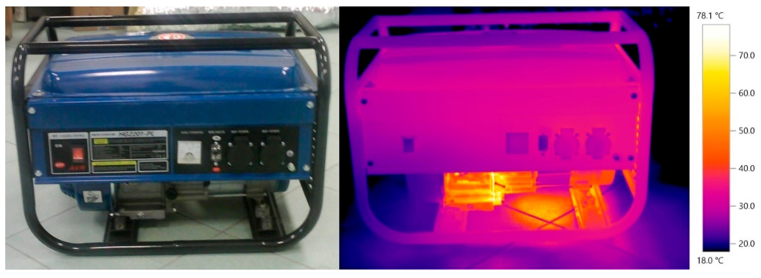
Figure 2.
Block diagram of the conceptual thermal-chamber system with the generator set and the heat pump, where: HP – heat pump, PG – generator set, ES – energy storage, DHS – low-temperature heat source, UHS – upper heat source.
Figure 2.
Block diagram of the conceptual thermal-chamber system with the generator set and the heat pump, where: HP – heat pump, PG – generator set, ES – energy storage, DHS – low-temperature heat source, UHS – upper heat source.
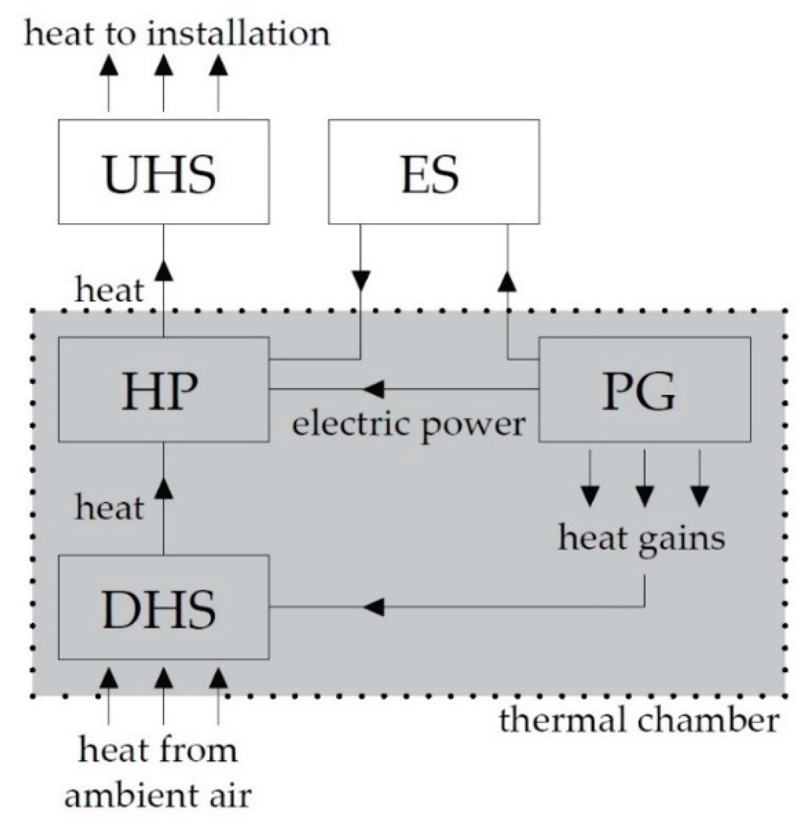
Figure 3.
Schematic layout of the thermal chamber with the generator set and the heat pump: 1 – insulated chamber, 2 – muffler, 3 – temperature sensor, 4 – control unit, 5 – fuel tank, 6 – fuel line supplying the generator, 7 – non-insulated exhaust outlet, 8 – air damper, 9 – air filter, 10 – insulated air duct supplying air to the generator, 11 – generator set 12 – heat pump, 13 – external air supplied to the generator.
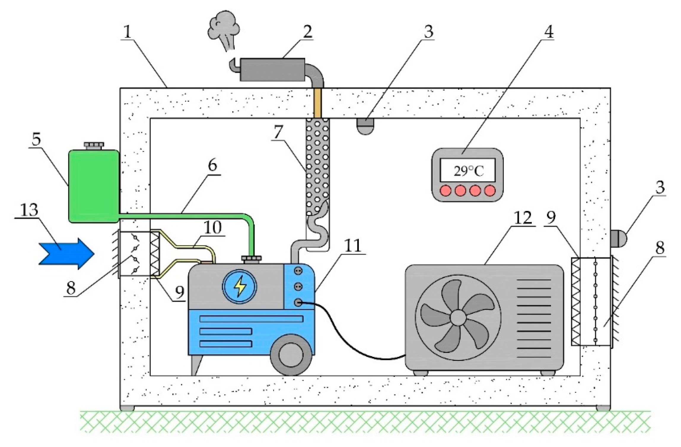
Figure 4.
Diagram of the test station, where: 1 – chamber, 2 – temperature sensor, 3 – exhaust outlet, 4 – air inlet, 5 – power generator, 6 – external temperature sensor, 7 – electricity receiver, electric heater.
Figure 4.
Diagram of the test station, where: 1 – chamber, 2 – temperature sensor, 3 – exhaust outlet, 4 – air inlet, 5 – power generator, 6 – external temperature sensor, 7 – electricity receiver, electric heater.
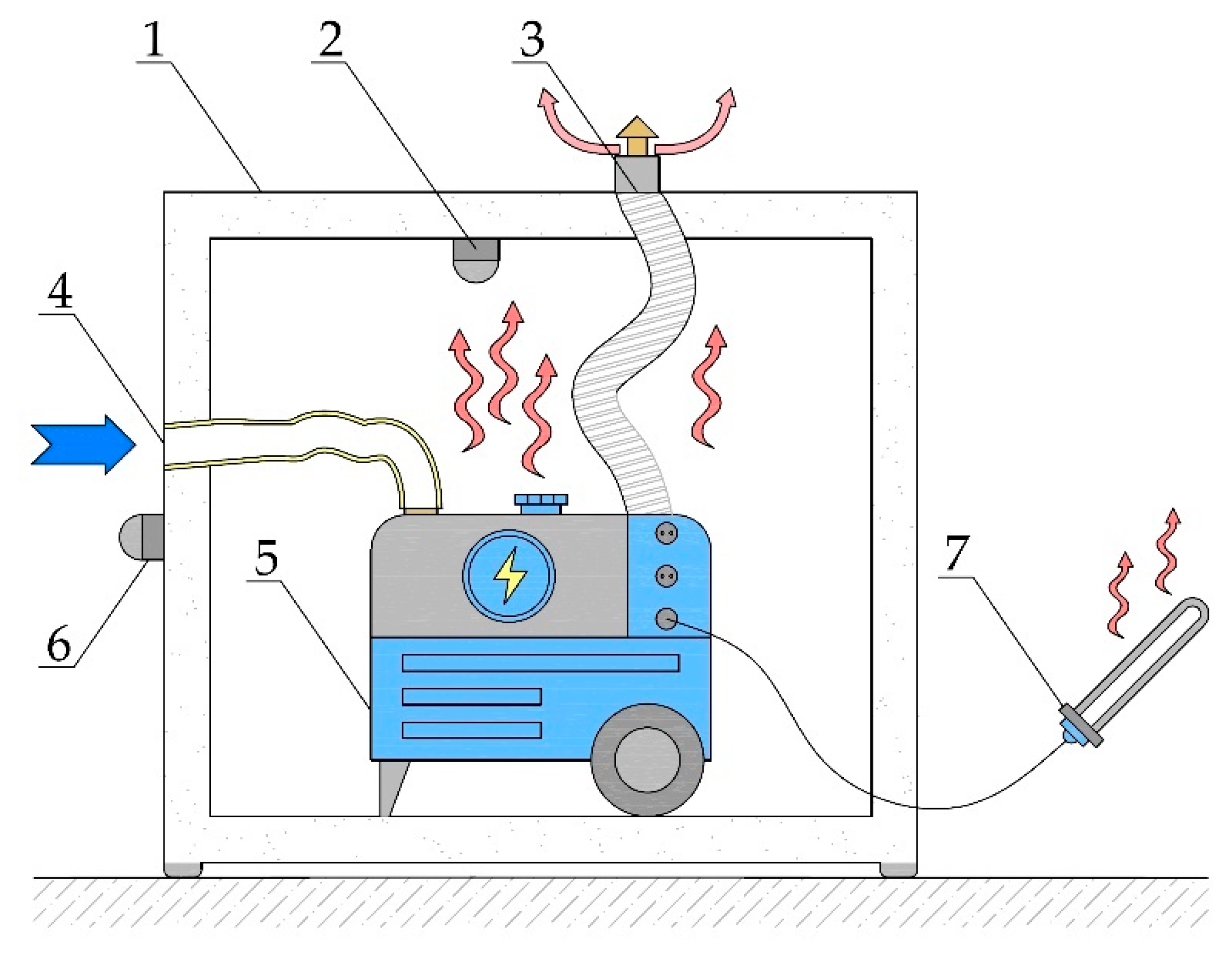
Figure 5.
The experimental setup, where: 1 – thermal chamber, 2 – temperature sensor, 3 – exhaust outlet, 4 – air intake, 5 – generator set, 6 – electrical load.
Figure 5.
The experimental setup, where: 1 – thermal chamber, 2 – temperature sensor, 3 – exhaust outlet, 4 – air intake, 5 – generator set, 6 – electrical load.
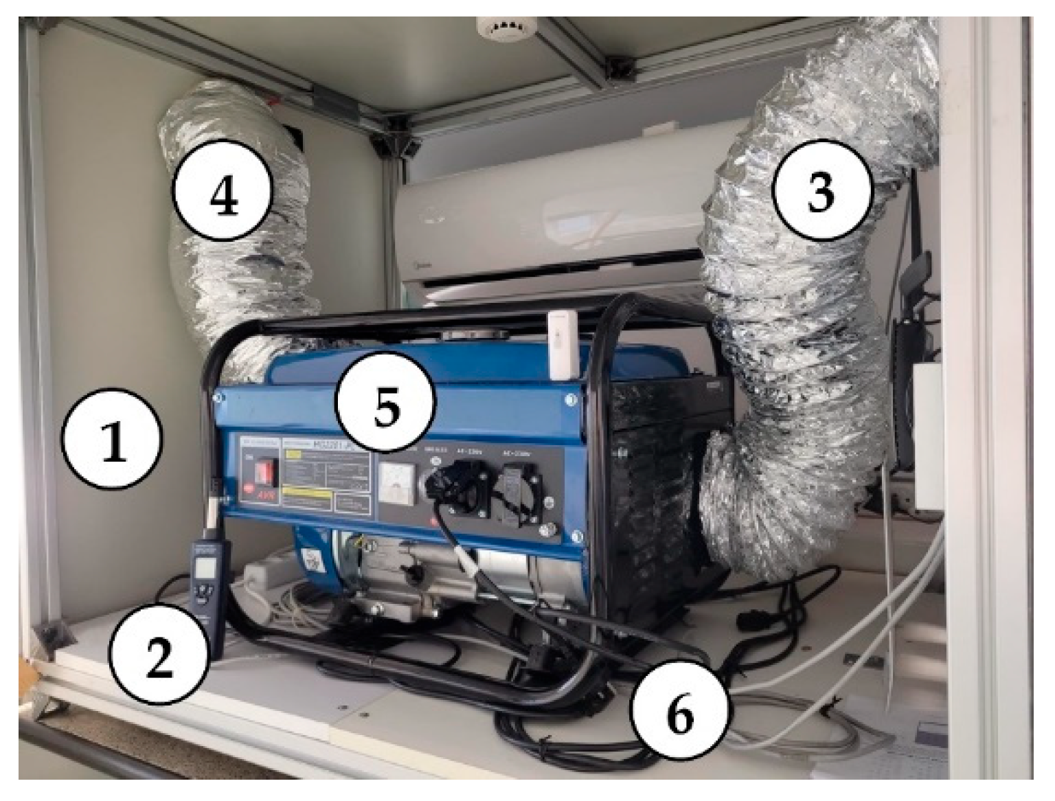
Figure 6.
Temperature and thermal power variation in the thermal chamber with a volume of 2.16 m3.
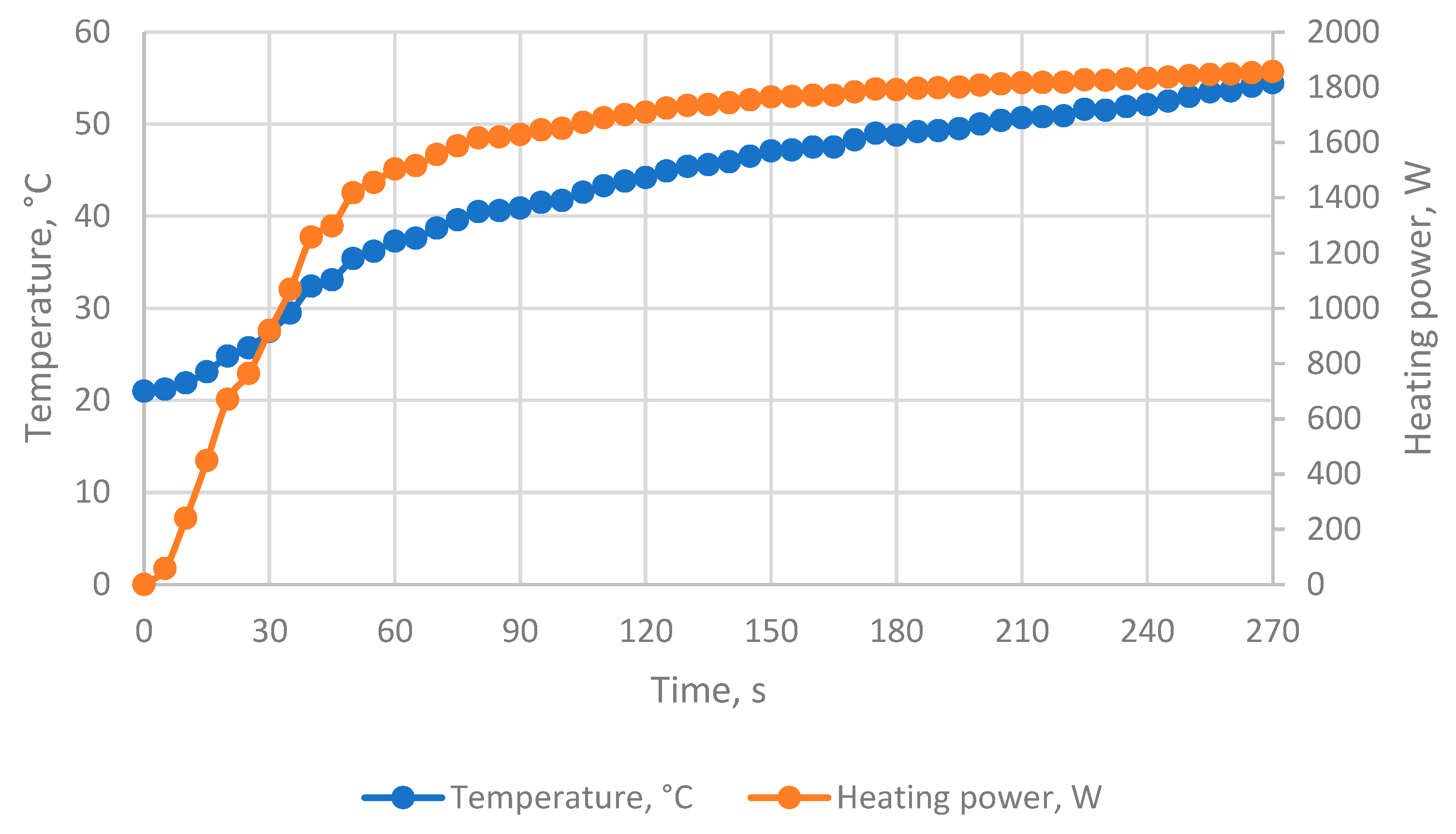
Figure 7.
Graph of the COP as a function of the heat pump outlet water temperature for the considered heating and domestic hot water systems.
Figure 7.
Graph of the COP as a function of the heat pump outlet water temperature for the considered heating and domestic hot water systems.
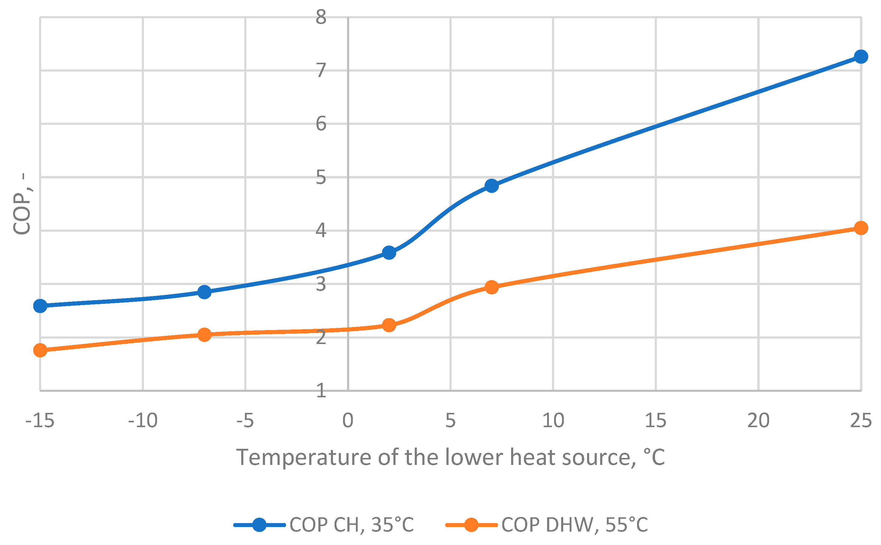
Figure 8.
Graph of COP values for the analyzed variants for space heating (CH) and domestic hot water production (DHW).
Figure 8.
Graph of COP values for the analyzed variants for space heating (CH) and domestic hot water production (DHW).
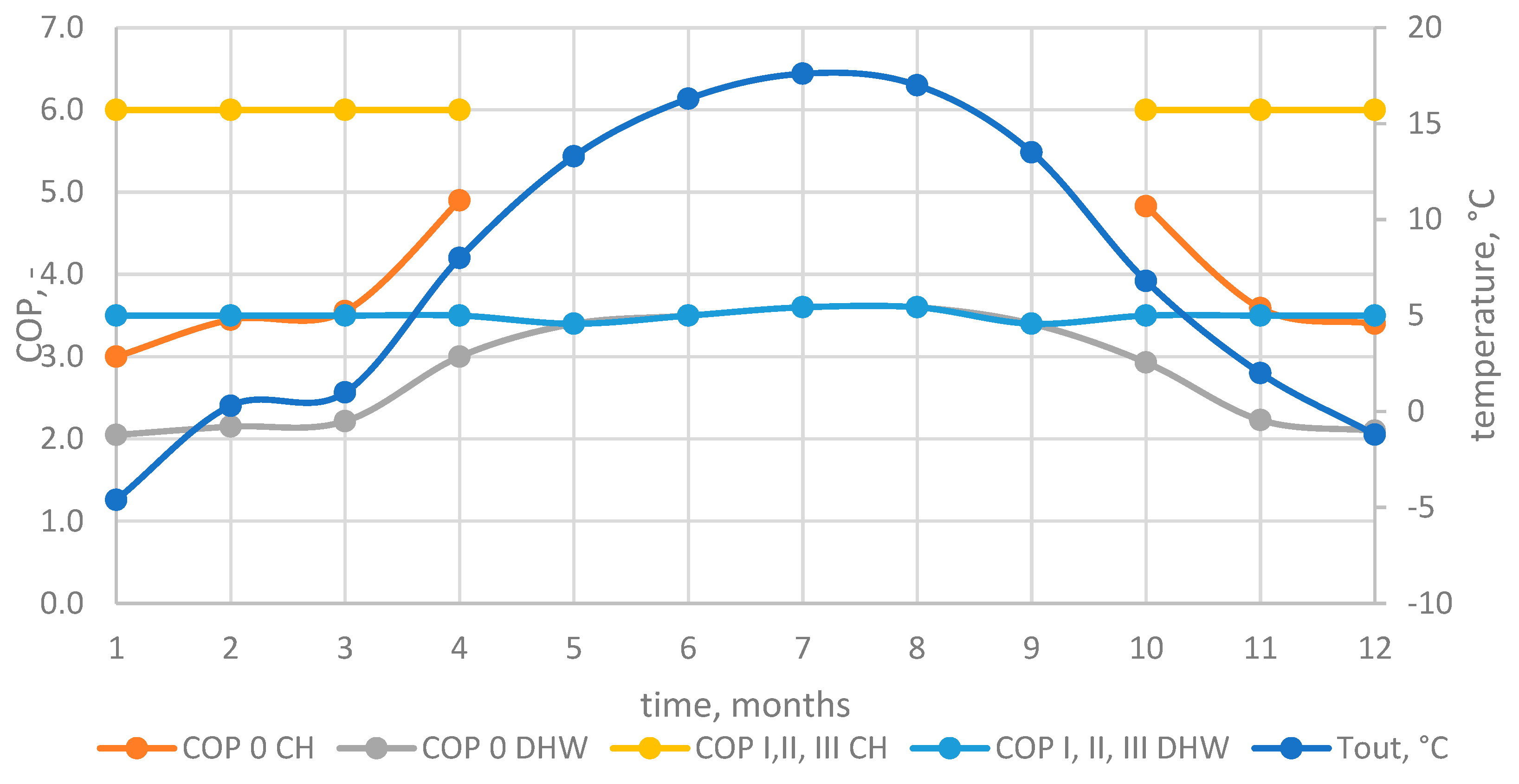

Table 1.
This is a table. Tables should be placed in the main text near to the first time they are cited.
Table 1.
This is a table. Tables should be placed in the main text near to the first time they are cited.
| No. | Parameter | Value |
|---|---|---|
| 1 | engine power | 7 KM |
| 2 | engine displacement | 212 cm3 |
| 3 | type of fuel | petrol |
| 4 | weight | 37 kg |
| 5 | maximum power | 2,2 kW |
| 6 | output voltage | 230 V |
| 7 | frequency | 50 Hz |
Table 2.
Theoretical energy distribution for electricity generation by a power generator with an electrical power of 2000W according to Sankey's assumptions.
Table 2.
Theoretical energy distribution for electricity generation by a power generator with an electrical power of 2000W according to Sankey's assumptions.
| No. | Parameter | Assumptions in line with the Sankey diagram |
|
|---|---|---|---|
| share, % [30] | power, W | ||
| 1. | Electrical power | 30 | 2 000 |
| 2. | Mechanical losses | 10 | 665 |
| 3. | Engine heat loss | 30 | 2 000 |
| 4. | Heat loss from exhaust gases | 30 | 2 000 |
Table 3.
Data concerning the domestic hot water preparation system.
| Month | TDHW (heat hours for DHW), h |
PDHW, kW | QDHW, kWh |
|---|---|---|---|
| I | 62 | 5.24 | 325 |
| II | 56 | 5.24 | 293 |
| III | 62 | 5.24 | 325 |
| IV | 60 | 5.24 | 314 |
| V | 62 | 5.24 | 325 |
| VI | 60 | 5.24 | 314 |
| VII | 62 | 5.24 | 325 |
| VIII | 62 | 5.24 | 325 |
| IX | 60 | 5.24 | 314 |
| X | 62 | 5.24 | 325 |
| XI | 60 | 5.24 | 314 |
| XII | 62 | 5.24 | 325 |
Table 4.
Data for the heat supply system for central heating.
| Month | TCH (heat hours for CH), h |
Tout, °C | PCH, kW | QCH, kWh |
|---|---|---|---|---|
| I | 682 | -4.6 | 3.43 | 2338 |
| II | 642 | 0.3 | 2.61 | 1608 |
| III | 682 | 1 | 2.49 | 1700 |
| IV | 660 | 8 | 1.32 | 874 |
| V | 0 | 13.3 | 0 | 0 |
| VI | 0 | 16.3 | 0 | 0 |
| VII | 0 | 17.6 | 0 | 0 |
| VIII | 0 | 17 | 0 | 0 |
| IX | 0 | 13.5 | 0 | 0 |
| X | 682 | 6.8 | 1.52 | 1040 |
| XI | 660 | 2 | 2.33 | 1535 |
| XII | 682 | -1,2 | 2,86 | 1951 |
Table 5.
Heat and electrical energy demand for central heating (CH) and domestic hot water (DHW) in Variant 0.
Table 5.
Heat and electrical energy demand for central heating (CH) and domestic hot water (DHW) in Variant 0.
| Month | Tout, °C | COPDHW 0 | QDHW, kWh | N el DHW 0, kWh | COPCH 0 | QCH, kWh | N el CH 0, kWh |
|---|---|---|---|---|---|---|---|
| I | -4.6 | 2.1 | 325 | 158 | 3.0 | 2 338 | 780 |
| II | 0.3 | 2.2 | 293 | 136 | 3.5 | 1 608 | 468 |
| III | 1 | 2.2 | 325 | 147 | 3.6 | 1 700 | 480 |
| IV | 8 | 3.0 | 314 | 105 | 4.9 | 874 | 179 |
| V | 13.3 | 3.4 | 325 | 96 | - | - | - |
| VI | 16.3 | 3.5 | 314 | 90 | - | - | - |
| VII | 17.6 | 3.6 | 325 | 90 | - | - | - |
| VIII | 17 | 3.6 | 325 | 90 | - | - | - |
| IX | 13.5 | 3.4 | 314 | 92 | - | - | - |
| X | 6.8 | 2.9 | 325 | 111 | 4.8 | 1 040 | 216 |
| XI | 2 | 2.2 | 314 | 141 | 3.6 | 1 535 | 428 |
| XII | -1.2 | 2.1 | 325 | 155 | 3.4 | 1 951 | 576 |
Table 6.
Heat and electrical energy demand for central heating (CH) and domestic hot water (DHW) in Variant I-III.
Table 6.
Heat and electrical energy demand for central heating (CH) and domestic hot water (DHW) in Variant I-III.
| Month | Tout, °C | COPDHW I, II, III | QDHW, kWh | N el DHW I, II, III, kWh | COPCH I, II, III | QCH, kWh | N el CH I, II, III, kWh |
|---|---|---|---|---|---|---|---|
| I | 15* | 3.5 | 325 | 93 | 6 | 2 338 | 390 |
| II | 15* | 3.5 | 293 | 84 | 6 | 1 608 | 269 |
| III | 15* | 3.5 | 325 | 93 | 6 | 1 700 | 284 |
| IV | 15* | 3.5 | 314 | 90 | 6 | 874 | 146 |
| V | 13,3 | 3.4 | 325 | 96 | - | - | - |
| VI | 16,3 | 3.5 | 314 | 90 | - | - | - |
| VII | 17,6 | 3.6 | 325 | 90 | - | - | - |
| VIII | 17 | 3.6 | 325 | 90 | - | - | - |
| IX | 13,5 | 3.4 | 314 | 92 | - | - | - |
| X | 15* | 3.5 | 325 | 93 | 6 | 1040 | 174 |
| XI | 15* | 3.5 | 314 | 90 | 6 | 1535 | 256 |
| XII | 15* | 3.5 | 325 | 93 | 6 | 1951 | 326 |
* chamber temperature.
Table 7.
Assumptions for variants I-III.
| Variant | ηel, % electricity generation efficiency |
ηrec, % waste heat recovery efficiency |
ηloss, % energy loss |
|---|---|---|---|
| I | 30 | 28 | 42 |
| II | 30 | 45 | 25 |
| III | 30 | 60 | 10 |
Table 8.
Annual operating costs for option 0.
| Variant | Electricity consumption, kWh | Energy price, €/kWh | Annual cost, €/year |
|---|---|---|---|
| central heating (CH) | 3 127 | 0.28 | 876 |
| domestic hot water (DHW) | 1 411 | 0.28 | 395 |
| Total | 4 538 | 0.28 | 1 271 |
Table 9.
Results of analyses for variants I-III.
| Parameter | Unit | Variant I | Variant II | Variant III |
| QCH X-IV | kWh | 11 045 | 11 045 | 11 045 |
| QDHW X-IV | kWh | 2 222 | 2 222 | 2 222 |
| QDHW V-IX | kWh | 1 603 | 1 603 | 1 603 |
| FC X-IV | l | 3 854 | 2 398 | 1 799 |
| C X-IV | € | 5 396 | 3 357 | 2 519 |
| FC V-IX | l | 153 | 153 | 153 |
| CV-IX | € | 214 | 214 | 214 |
| FC total | l | 4 007 | 2 551 | 1 952 |
| Ctotal | €/year | 5 610 | 3 571 | 2 733 |
| Eel X-IV | kWh | 11 562 | 7 194 | 5 396 |
| Eel V-IX | kWh | 458 | 458 | 458 |
| Eel total | kWh/year | 12 020 | 7 652 | 5 854 |
| Eel + | kWh/year | +9 086 | +4 719 | +2 920 |
Disclaimer/Publisher’s Note: The statements, opinions and data contained in all publications are solely those of the individual author(s) and contributor(s) and not of MDPI and/or the editor(s). MDPI and/or the editor(s) disclaim responsibility for any injury to people or property resulting from any ideas, methods, instructions or products referred to in the content. |
© 2025 by the authors. Licensee MDPI, Basel, Switzerland. This article is an open access article distributed under the terms and conditions of the Creative Commons Attribution (CC BY) license (https://creativecommons.org/licenses/by/4.0/).
Copyright: This open access article is published under a Creative Commons CC BY 4.0 license, which permit the free download, distribution, and reuse, provided that the author and preprint are cited in any reuse.


