Preprint
Review

This version is not peer-reviewed.

Problems with in Take Air Filtration in Piston and Turbine Combustion Engines Used in Conditions of High Air Dust Content

A peer-reviewed article of this preprint also exists.

Submitted:

07 November 2025

Posted:

07 November 2025

You are already at the latest version

Abstract

The operating conditions of engines in motor vehicles used in conditions of high air dustiness resulting from sandy ground and in helicopters using temporary landing sites were analyzed. The impact of mineral dust on accelerated abrasive and erosive wear of components and assemblies of piston and turbine engines was presented. Attention was drawn to the formation of dust deposits on turbine engine components. The possibilities of minimizing abrasive wear by using two-stage intake air filtration systems in motor vehicle engines were presented. The filtration properties of cyclones used as the first stage of air filtration were discussed. Three forms of protection for helicopter engines against the intake of contaminated air and to extend their service life were presented: intake barrier filters (IBF), tube separators (VTS), and particulate separators (IPS) called Engine Air Particle Separation (EAPS). It has been shown that pleating the filter bed significantly increases the filtration area without increasing the frontal area, whereby optimization of the filter bed geometry is of great importance here. An important advantage of the VTS air filtration system was demonstrated in the form of no maintenance due to the use of a system for the continuous removal of separated dust, whereby increasing the suction flow increases separation efficiency and pressure drop and energy losses. IPS is an air filtration system integrated with a turbine engine, characterized by a compact design, low external resistance, and no periodic maintenance, but with lower separation efficiency than VTS and IBF systems. The primary goal of such systems is to separate as many solid particles as possible at the lowest possible energy cost. The results of experimental research conducted by the author are presented, the aim of which was to demonstrate the advantages of a filtration unit consisting of cyclones and a porous partition in terms of increased filtration efficiency and filter operating time. During the research, an innovative method was used to determine the characteristics of a barrier filter operating in a two-stage filtration system, which reduces testing time and energy losses. It was a single VTS axial flow cyclone with a test barrier filter arranged in series behind it, whose filter bed was pleated paper with a suitably selected surface area. The results confirmed the advisability of using two-stage filtration systems to purify the intake air for internal combustion engines of motor vehicles and helicopter turbine engines. Since a porous partition increases pressure drop during operation, it is advisable to use permissible resistance sensors to limit their use due to increasing engine energy losses.

Keywords: 
;  ;  ;  ;  ;  ;  ;  

1. Introduction

Atmospheric air is the basic component of the working medium in piston and turbine combustion engines. The air flow sucked in by the engine is proportional to the engine power. From the unit flow (1 kg/s - 2800 m³/h) of air needed for complete fuel combustion, an average of 700 kW of power is obtained in piston engines and approximately 200 kW in turbine engines. The significantly higher air demand per unit of power in turbine engines results from high air excess coefficients, which are necessary to limit the exhaust gas temperature affecting the strength of the turbines.
The air flow sucked in by an internal combustion engine depends on many design factors, including the engine displacement Vss, the crankshaft speed n, and the cylinder filling ratio ηυ, which depends on the presence of an intercooler. For passenger car engines, the air intake ranges from 150 to 400 m3/h, while for truck engines the values are significantly higher, at 900 to 2000 m3/h. The highest values of volumetric air demand (3500-6000 m3/h) are found in compression ignition engines (CI), which are the power units of special vehicles (tanks, transporters) characterized by high power. Turbine engines used to power helicopters are characterized by the fact that, in order to operate properly, they draw large amounts of air from the atmosphere, on average 1.7-5.0 kg/s (5000-14500 m3/h) of air [1,2]. Similar intake air flow rates are supplied to the Abrams tank engine, where the power unit is a turbine that requires 5.36 kg/s (15,500 m3/h) of air for proper operation [3].
The atmosphere contains various solid, gaseous, chemical, and biological pollutants that are emitted into the atmosphere by natural and artificial sources. The main component of air pollution is mineral dust, which settles on the ground and is lifted by passing vehicles or by the wind. Particularly large amounts of dust are found in the air when vehicles are used on dry, unpaved terrain (off-road), sandy and desert terrain, and when helicopters are operated on temporary landing sites. The dust concentration is then particularly high, reaching values of up to 10 g/m3 when a column of tracked vehicles moves over dry ground [4,5,6,7,8,9,10].
Helicopters may encounter dusty environments during ground flights, especially during desert operations. During takeoff or landing of a helicopter on a temporary landing site, the dust concentration in the air at the height of the CH-53 helicopter propeller tip (0.5 m above the ground) can reach a value of s = 3.33 g/m3 of operation [11]. Dry dust can also occur at high altitudes in areas such as Australia, the Middle East, some Asian countries, Africa, and some states in the USA.
According to the authors of the study [12], a dust content in the air of 0.6-0.7 g/m3 causes a significant reduction in visibility. At a concentration of approximately 1.5 g/m3, visibility is reduced to zero, which adversely affects driving or helicopter piloting safety. Limited visibility of the horizon can cause helicopter accidents related to human factors during military operations.
Along with the air intake, engines suck in significant amounts of solid pollutants from the atmosphere, mainly mineral dust. The engine of a tracked vehicle with a power of 700 kW and an air flow of 3400 m3/h, which is used on sandy roads (dust concentration s = 1g/m3), absorbs over 170 kg of dust, or about 0.057 kg per minute, along with the air during 50 hours of operation at maximum load (1000 km mileage). A helicopter with an engine air requirement of 5.9 kg/s (approximately 17,000 m3/h) and an airborne dust concentration of 2.5 g/m3 sucks in approximately 0.7 kg of dust per minute along with the air [11].
When the dust mass concentration exceeds 1.177 grams per cubic meter of air, this condition is known as a “brownout” [13], although the term is more generally used for all situations where a dust cloud forms. Based on this figure, an unprotected engine with a mass flow of 12.5 kg/s could absorb approximately 7 kg of particulate matter in ten minutes in such a dust cloud and could lose one percent of its power.
For example, the Boeing CH-47/Chinook1 helicopter is powered by two turbine engines, each with a rated power of 3750 hp at the shaft (2800 kW). To generate this power, an intake air flow of 11 m3/s (3900 m3/h) is required. With an average dust concentration in the air of 2.5 g/m³, the engine sucks in approximately 1.65 kg of dust per minute along with the air [14].

2. The Impact of Mineral Dust on the Operation of Internal Combustion Engines

The main effect of dust particles entering combustion engines with the intake air stream is accelerated abrasive and erosive wear of individual parts and entire structural assemblies of piston and turbine engines, as well as the formation of dust deposits on turbine engine components. Both effects simultaneously cause a deterioration in power characteristics, fuel consumption, and oil consumption.

2.1. The Impact of Mineral Dust on the Wear of Components and the Operation of Piston Engines

Large amounts of dust sucked in from the environment along with the intake air into the engines cause accelerated wear of engine components and dust accumulation in the intake ducts of turbine engines. In the case of piston engines, abrasive wear has a negative impact on their performance in the form of reduced power and increased fuel consumption. In the case of turbine engines, erosive wear of the blades and significant amounts of dust accumulated in the flow ducts result in a decrease in power and even immobilization of the helicopter engine, leading to a crash. The negative impact of dust on piston and turbine engine components varies due to their different designs.
Dust particles in the air intake to the piston engine and in the oil of the engine lubrication system have a detrimental effect on engine components in different ways (Figure 1), consisting of:
  • the formation of a layer of dust and other contaminants on the measuring element of the flow meter, which, due to its insulation properties, limits heat exchange with the flowing air stream and generates an incorrect signal,
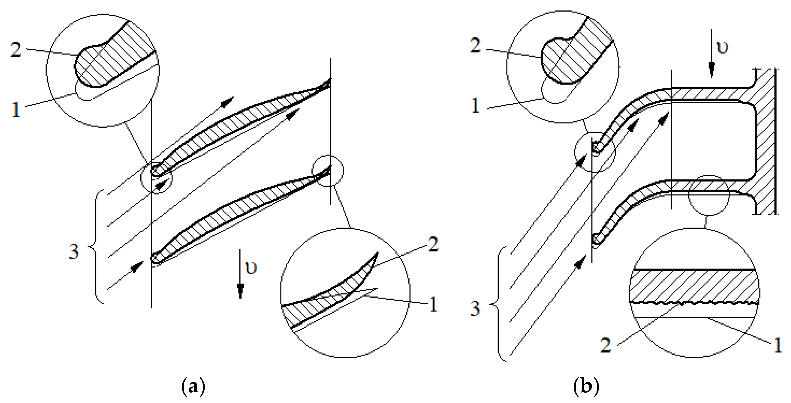
  • erosive wear of the compressor and turbine blades of the supercharger,
  • abrasive wear of the P-PR-C components performing reciprocating motion,
  • abrasive wear of the “valve stem-guide” components performing reciprocating motion,
  • erosive wear of the seats and poppets of the intake and exhaust valves,
  • abrasive wear of the sliding bearing components (journal-bearing shell) of the crankshaft, camshaft, and turbocharger shaft,
  • abrasive wear of other friction-operated assemblies supplied with lubricating oil (cam-valve disc, valve levers,
  • formation of a layer of molten dust particles on the catalytic surface of reactors, resulting in reduced efficiency.
Dust, whose main components are silica SiO2 and corundum Al2O3, has a destructive effect on both piston and turbine engine parts after entering the engine. However, the mechanism of interaction between dust particles and piston engine components is completely different from that of turbine engines. In a piston engine, the harmful effect of dust particles contained in the air entering the engine is complex, due to their varying size and hardness and the thickness of the oil film. Particles smaller than the thickness of the oil film should not damage the surface, but they can weaken the oil film [15] and cause oil thickening [16]. The dynamic thickness of the oil film ranges from 0.1 to 50 µm [15,17], but may approach 0 at the top of the cylinder [15,18]. Typically, the oil film thickness is usually greater than 1 µm, and most dynamic clearances are in the range of 0-20 µm [16].
In the first stage, hard mineral grains that have entered the engine’s piston space with the air stream and then settled on the cylinder walls penetrate between the mating surfaces of the P-PR-C association, where the piston with rings performs a reciprocating motion in a stationary cylinder, and in the case of a thin oil film, they cause abrasive wear. When abrasive particles pass between two surfaces, they can tear off metal chips or become deposited in the outer layer of the engine part. In addition, during engine operation, the particles can be crushed into smaller ones. The movement of the piston towards the bottom dead center (BDC) causes some of the oil to be scraped into the oil pan along with the dust, from where the oil pump draws and then transports the oil under pressure along with the dust to many friction pairs in the engine (main and connecting rod bearings of the crankshaft, camshaft bearings, valve stems and rocker arms, valve guides, valve cams, turbocharger shaft slide bearings), which require continuous lubrication. The dust particles contained in the oil and delivered in this way to the engine’s friction points cause accelerated wear. This is the second stage of the harmful effect of dust particles delivered with the air intake to the engine. Dust particles can also enter the engine oil directly from the environment, for example through the crankcase ventilation system during maintenance work (oil change), but these quantities are negligible. Individual engine components are subject to different loads, have different clearances and lubrication requirements.
Numerous studies have shown that the P-PR-C components and the valve-seat contact area are subject to the greatest wear, resulting in increased leakage in the combustion chamber and causing a drop in compression pressure, engine power, and an increase in specific fuel consumption [19,20]. In addition, the increasing clearance in the P-PR-C assembly systematically increases the flow of exhaust gases into the oil pan, which causes an increase in the temperature of the lubricating oil, a decrease in its viscosity, and increased wear on the rings and cylinder [21]. Excessive wear of the “bore-bearing” combination causes a drop in lubrication pressure, which results in a reduction in oil film thickness and increased wear, up to and including engine seizure.
Dust particles in the intake air stream settle on the flow meter’s measuring element, hindering heat exchange, which generates a lower electrical signal, resulting in a lower air flow value. As a result, the on-board computer does a smaller amount of fuel, which results in a decrease in engine power and an increase in toxic exhaust emissions.
The high peripheral speeds of the compressor rotor blade in the turbocharger, resulting from the high rotational speed of up to 200,000 rpm at full engine load, cause a high impact force upon contact with dust particles flowing at a speed of approximately 100 m/s in the air stream. s in the air stream. As a result, metal microparticles are torn from the surface of the blades (erosive wear), which damages their surface structure and geometric shapes. This results in a reduction in the efficiency of the turbocharger and, consequently, a reduction in engine filling and power. A similar phenomenon of erosion wear occurs when the tips of the turbine rotor blades, which have circumferential speeds of around 800 m/s, come into contact with dust particles moving with the exhaust gases at high speeds of around 300 m/s. These are mineral dust particles that have entered from the supercharged space along with the exhaust gases. According to the authors of [15,22], the exhaust gases contain approximately 30% of the dust that has left the air filter and reached the engine cylinders.
Some (approximately 10-20%) of the airborne contaminants that enter the engine cylinders settle on the cylinder liner walls, some are removed with the exhaust gases, and some of the dust undergoes thermal processes, such as melting. At high temperatures (2300-2800K), the mixture of clay raw materials, sand with the addition of sodium and potassium compounds, as well as iron, forms glaze-like alloys of varying composition, which can settle on the surfaces of engine components and on the surface of the reactor’s catalytic layer. The catalytic layer is made of platinum, palladium (oxidants) or rhodium (reducers), whose task is to facilitate and accelerate the chemical transformation of toxic exhaust components: CO, CH, NOx, covered with such glaze, reduces or even loses its catalytic properties and does not fulfill its intended role.
This is due to the fact that each of the polymorphic varieties of SiO2 quartz (tridymite and cristobalite) is stable within a certain temperature range. At a temperature of 1600°C, quartz melts to form quartz glass [23]. Tridymite is stable in the range of 870-1470°C and melts at 1670°C when heated. Crystobalite α is stable in the range of 1470-1710°C and then melts to form glass.

2.2. The Impact of Mineral Dust on Component Wear and Turbine Engine Operation

In turbine engines, due to the absence of reciprocating parts, the mechanism of dust particle impact on engine components is different than in piston engines. The main impact of dust particles entering turbine engines with the inlet air stream is the erosive wear of high-pressure compressor and turbine blades and the formation of dust deposits in air flow channels.
The turbine assembly wears much more slowly than the compressor, due to the significant fragmentation of the particles that have passed through the compressor and combustion chamber, as well as the greater erosion resistance of the materials used in the turbine parts, especially the turbine blade guides. Contamination of the axial compressor is caused by fine particles adhering to the surface of the blades, which increases the roughness of the blades and, as a result, changes the shape of the profile. Despite the presence of filters in the inlet duct, particles can reach the axial compressor due to their small diameter, which is generally less than 2-10 μm [24]. Typically, these particles can be removed by proper cleaning of the compressor.
High air flow velocities (150-250 m/s) and exhaust gas velocities (over 300 m/s), high peripheral speeds of rotor assemblies (200-500 m/s) cause dust particles, especially large ones, to have significant kinetic energy when they come into contact with the surfaces of turbine engine components, resulting in high impact force [25]. This results in accelerated wear due to the removal of metal microparticles from the surface of the parts, increased roughness, and damage to their surface structure and geometric shapes. As a consequence, the efficiency and durability of the engine are reduced.
An increase in roughness causes a decrease in air mass flow to the engine due to additional blockage, accompanied by a decrease in pressure ratio and efficiency. Literature reports indicate efficiency and power output losses ranging from 2% for mild roughness to 15-20% for highly rough blade surfaces [26,27]. Therefore, continuous operation, during which particles enter the engine inlet, reduces its performance, shortens the service life of components, and affects their reliability [28]. The authors of [29] presented an overview of the deterioration of turbine machines and described the relationship between the condition of the blade surfaces and the deterioration of engine performance. Changes in the geometry of compressor blades caused by erosion occur in several forms. In compressors, erosion increases the clearance at the blade tips, shortens the blade chord, increases the roughness of the pressure surface, blunts the leading edge, and sharpens the trailing edge. Particles are spun off after the first impact with the rotor, which limits erosion damage to the outer areas in subsequent stages. Increased clearance at the tips and changes in the shape of the rotor blade profile caused by erosion result in a deterioration in their performance. Inertial impacts at high speeds of particles larger than a few micrometers in diameter on the leading edges of the profile and pressure surfaces can cause erosion or deposition, depending on the balance between hard and molten particles. The deposition of smaller particles on the suction surfaces of the profile is associated with turbulent diffusion/vortex impact. Deposition is expected to be more significant in the early stages of hot turbine section operation, as turbine inlet temperatures increase due to the higher proportion of molten particles. Engine performance deterioration, including increased fuel consumption, decreased efficiency, throughput, and reduced power reserves, is attributed to fan and compressor erosion.
The most intense wear occurs on the inlet stages of compressors and fans of bypass engines, less on turbines, and least on combustion chambers. According to the authors of [30], the compressor is the most intensively worn component in turbine propeller and helicopter engines. It is estimated that compressor contamination is typically responsible for 70% to 85% of the total loss of gas turbine efficiency during continuous operation [29]. Radial compressors are more resistant to wear, with the most intensive wear occurring on the impeller blades and diffusers. This type of compressor is commonly used in devices for supercharging piston combustion engines.
Figure 2 shows the areas of wear on the rotor blades of axial compressors and radial compressors, with the paths of dust particles moving in the compressor flow channels marked. Large dust particles with significant energy can cause erosive wear in the form of permanent deformation: blunting of the leading and trailing edges of the rotor blades of axial compressors, reduction of the chord of the blades, and increased roughness of the surface and leading edges of the blades of radial compressors. The effect of solid particles in the form of erosion of the front and rear edges of turbine engine compressor blades is shown in Figure 2.
Smaller and lighter grains cause abrasion and tear out particles of material from the surface of these blades, damaging the top layer and changing the shape of the aerodynamic profiles of the blades, which leads to a deterioration in compressor efficiency and a tendency to unstable operation at ranges close to operating ranges.
The amount of dust sucked into the engine’s flow channel is determined by the concentration of dust in the air and the operating time in a dusty environment. Since, as a result of impact erosion, each dust particle causes metal loss only at the point of impact, the amount of wear is proportional to the number of particles in the stream, i.e., directly proportional to the dust concentration and the operating time in the sucked air. As the size of the dust particles and the concentration of dust in the air increase, the intensity of wear on the engine components increases and, consequently, the durability of the engine decreases (Figure 3).
The intensity of wear is determined by hard dust particles with irregular sharp edges, especially SiO2 and Al2O3, and the size of the dust particles, although this relationship is not linear (Figure 4). Although large dust particles accelerate wear, studies show that even fine dust particles (with diameters of 5...7 µm) cause sufficiently rapid wear, leading to a reduction in the inter-repair durability of compressors and a deterioration in their efficiency and compression parameters (efficiency and compression).
Abrasive erosion is typical for centrifugal compressor rotor blades. It is caused by dust particles which, when moving along the interblade channels with the air stream, are pressed against the working surfaces of the blades by aerodynamic and inertial forces.
Erosion wear caused by dust entering turbine engines has proven to be a dangerous phenomenon when operating helicopters in conditions of high air dust content. This leads to a reduction in the reliability of the power unit, especially in the case of helicopters. Experience gained during field operations in Vietnam shows that 40-60% of all causes of premature (before the end of the guaranteed service life) return of helicopter engines for repair were related to the harmful effects of a dusty atmosphere. These engines very often did not even reach 30% of their normal service life. Some engines had to be taken out of service after less than 100 hours of use [31,32]. During the first Gulf War, unfiltered CH-47 Chinook helicopters with Lycoming T-53 engines required repairs after only 25 hours of operation [11]. Similarly, during Operations Desert Storm and Desert Shield in the early 1990s, GET-64 engines had to be replaced after approximately 120 hours of operation [33].
The Russians gained extensive experience in this area by operating TW3-117 engines in Afghanistan. As a result of operating in such difficult conditions, only 50-60% of Mi-24 helicopters were able to meet the imposed overhaul intervals, and in the case of the Mi-8 helicopter, this level was lower, at 40-50% [34].
In the channels of the turbine nozzle rings, however, dust deposits bound by combustion products as a binder are formed. This applies only to the corners of the walls formed by the control vanes and their shelves or feet, or the walls of the hulls or control vane mounting rings. The formation of dust deposits results from the tendency of fine dust particles to settle on the surfaces of compressor and turbine casings, combustion chamber covers, axial compressor blade rings (mainly the last ones) and turbine nozzle rings (mainly the first stages). The tendency to form dust deposits is increased by sticky admixtures in the gas stream, e.g., exhaust gases, oil mist, etc.
Dust deposits in compressors do not have a hard structure, while in combustion chambers and turbines they occur in the form of brittle hard layers composed mainly of inorganic substances. There are also certain characteristic engine operating ranges where dust deposit formation is most intense.
Layers of dust deposits do not form structures permanently bonded to the substrate (walls), so they can be removed by periodically adding mechanical agents (e.g., nut shells) or softening agents to the inlet stream. Sometimes, a rapid change in the engine’s operating range is sufficient to destroy the sediment structure.
The process of dust deposition and accumulation is very rapid. Dust deposits do not cause wear on engine components, but only change their geometric dimensions, which leads to modifications in the flow path, changes in surface smoothness, and deterioration of heat exchange processes. In addition, a significant amount of absorbed silicate-based dust melts at high temperatures (1150-1250°C) and forms deposits known as CMAS (calcium-alumina-magnesium-silicate) glass on the first stage of the NGV. CMAS deposits can cause long-term thermal corrosion of the barrier coating. The rapid temperature increase caused by this phenomenon is believed to be the cause of rapid loss of turbine efficiency and power. This is particularly important for heat exchange channels. The thickness of the layer of dust deposits formed depends on the mass of dust sucked in by the engine, i.e., as in the case of erosion, on the concentration of dust in the air and the operating time of the engine in a dusty environment.
The main effect of dust particles entering turbine engines with the intake air stream is accelerated wear of individual parts and entire engine assemblies, as well as the formation of dust deposits (Figure 5). Both effects simultaneously cause a deterioration in power characteristics, fuel consumption, and oil consumption (Figure 6). Although CMAS can cause long-term thermal corrosion of the barrier coating, it is believed that the rapid increase in this case was caused by a rapid loss of turbine efficiency.
The graph in Figure 6 shows the change in turbine engine power (caused by both erosion and dust deposits) as a function of the mass of dust sucked in. It shows that the impact of both factors (erosion and deposits) is comparable. The decrease in engine power increases in proportion to the mass of dust sucked in by the engine. Periodic removal of dust deposits allows for a separate quantitative assessment of the effects of erosion and sedimentation.
The works [31,32,36] present examples of the harmful effects of dust on military vehicle turbine engines resulting from excessive dust concentration in the intake air, which, in the absence of an adequate filtration system, causes the absorption of large amounts of dust that accumulates on the turbine blades.
This causes disturbances in air flow and fuel combustion, sudden engine throttling, power loss, and turbine shutdown, resulting in helicopter crashes. Similar problems with the proper operation of turbine engines as a result of mineral dust accumulation on their components have occurred in passenger aircraft that have encountered volcanic dust clouds at altitudes of 7,000-12,000 m [37,38].

3. Filtration of Air Intake for Motor Vehicle Engines

The only effective and active method of purifying intake air, and thus also eliminating the harmful effects of dust on the components of internal combustion engines of motor vehicles used in highly dusty air, is the use of sufficiently effective air filters, which are required to have a filtration efficiency of 99.5-99.9% for dust particles larger than 2-5 µm and long service intervals. For this reason, the engines of trucks, special vehicles, including military vehicles and work machines, are equipped with filters with a two-stage filtration system (Figure 7).
The essence of the two-stage filter operation is to combine two different air filtration processes occurring in two separate devices, whose operation is different, which makes these devices complement each other. The first stage of filtration is a multicyclone, which is a set of several dozen (several hundred) identical, side-by-side reverse or straight-through cyclones with internal diameters not exceeding D = 40 mm (Figure 8), which uses centrifugal force to separate solids or liquids from gas.
Dust particles in the air stream are set in a helical motion (external vortex) when tangentially fed into the cylindrical part of the cyclone or axially fed onto the rotor blades located at the cyclone inlet, as a result of which they acquire a centrifugal force described by the following relationship:
F B = m z · u s 2 r
where: mz – mass of the dust particle, us – tangential component of the grain velocity (approximately equal to the tangential component of the gas velocity υs), r – distance of the dust grain from the axis of rotation.
Centrifugal force causes the grain to move towards the inner wall of the cyclone at a speed of ur, while performing a spiral motion with an increasing radius. The movement of the dust grain is slowed down by the resistance force FR, determined by the following relationship:
F R = λ · A p · u r 2 2 · ρ g
where: Ap – projection area of the dust particle, ur – radial motion component of the particle, ρg – gas density, λ – friction coefficient depending on the shape of the particle and the Reynolds number.
Particles with a large mass and particles with a smaller mass but which simultaneously achieve a high velocity obtain a centrifugal force large enough to overcome the force of air resistance and follow a spiral motion towards the inner wall of the cyclone. The equation of motion of dust particles resulting from the balance of forces will then take the form [39]:
m z d u r d t = F R + F B + F M + F C + F G
where: FR – air resistance force, FB – inertia force, FM – Magnus force (generated by the rotation of particles in the force flow field), FC – force between particles and the cyclone wall, as well as the force resulting from collisions between particles, FG – gravitational force.
The shape of the spiral path along which the dust particles move will then depend on the mutual relationship between the values of forces FB and FR. The value of both forces depends on the size and material of the dust particles (density), which determine the mass and value of the centrifugal force, as well as the size, shape of the dust particles and the type of gas flowing, which affect the resistance force of the medium. After several rotations around the cyclone axis, the dust particle reaches the surface of the cyclone wall, which results in a reduction in its speed, and then, spinning along the cyclone wall, it moves to the collection chamber and then to the sedimentation tank, which means that it is separated from the air stream.
During this time, the particles are driven mainly by the spiral flow of air and to a lesser extent by the force of gravity. This applies to dust particles of a certain mass and diameter greater than a certain dimension dpg, defined as the limit particle diameter, for which the condition FR < FB applies. On the other hand, dust particles with diameters smaller than the dpg dimension, for which FR > FB, will move along a spiral line, but will be directed by the internal air vortex to the center of the cyclone and then towards the cyclone outlet pipe.
Individual cyclones of the same diameter, which usually does not exceed 40 mm, are placed parallel to each other, and their ends are tightly fixed in a common top and bottom plate, forming a multicyclone consisting of several dozen (several hundred) filter elements.
Contaminants stored in the multicyclone sedimentation tank should be removed. This operation is performed periodically during filter maintenance. In filters of vehicles used in conditions of high air dustiness, the dust collected in the multicyclone sedimentation tank is removed on an ongoing basis (outside the vehicle) thanks to the creation (using the phenomenon of ejection) of a suction stream QS, which is part of the inlet stream (contaminated) Q0 to the multicyclone.
To generate the suction stream, appropriate ejectors (Figure 9) are used as flow-forcing devices, utilizing the energy of the compressed air stream or the energy of the exhaust gases flowing out of the engine exhaust system [40,41,42]. Special fans or blowers are also used to generate the suction stream.
Of the ejector configurations shown above, the configuration shown in Figure 10 is more practical and more commonly used in exhaust systems. It is characterized by a much simpler design and lower weight, which is important in the case of exhaust systems that are usually subject to vibration. This ejector configuration is found in the ejection system for removing contaminants from the air filter sedimentation tanks of tanks and special vehicles built on the chassis of these tanks.
The ejector is characterized by a very simple design, a small number of components, and no moving parts. It requires minimal operational supervision, which boils down to periodic visual inspection of the technical condition of the ejector and the tightness of the connecting pipe to the sedimentation tank. On the other hand, however, the use of an ejector requires an increase in the energy used to generate suction flow.
The second stage of filtration is a cylindrical filter cartridge made of pleated filter paper or a multi-layer bed composed of various materials, such as cellulose-polyester-nanofiber, cellulose-polyester, polyester-glass microfiber-cellulose. Such filter beds are characterized by low thickness (0.6-0.9 mm) and low absorbency (200-250 g of dust per m2), but high efficiency (99.5-99.9%) and accuracy of filtration of dust particles above 2-5 µm.
The structure of the filter bed is a three-dimensional, disordered structure consisting of filter material fibers. An image of the structure of filter materials obtained using a scanning electron microscope of polypropylene microfiber and cellulose filter material is shown in Figure 11.
Filter materials are characterized by the following basic parameters provided by the manufacturer: weight, thickness, average pore size, fiber diameter, contaminant absorption, air permeability, tear strength, maximum or average pore diameter, and resin content. The thickness of filter papers does not exceed 1 mm and is usually in the range of 0.5-0.9 mm, with the diameter of cellulose fibers ranging from 15-20 µm. The average pore diameter ranges from 40-90 µm.
In the filter bed, dust particles moving in line with the flow of the medium are retained and collected on individual fibers as a result of several filtration mechanisms acting simultaneously [45,46,47], such as gravitational settling, inertial impact, interception, diffusion, and electrostatic forces (Figure 12). The first four are known as mechanical mechanisms. Gravitational settling is of lesser importance for most particle sizes, as the contribution of gravity to the filtration process appears to be minimal. Gravitational sedimentation can be completely ignored if the particle size is less than 0.5 µm [46].
Inertial impact occurs when a particle, due to its inertia, moves away from the initial gas stream line and hits the fiber. The trapping mechanism occurs when a particle has a finite size and begins to settle when it is one particle radius away from the fiber surface. For particles smaller than 0.1 µm, diffusion may be strong enough to move them from their original streamlines to the fiber due to the random motion of the particles. Electrostatic forces occur when particles or fibers carry electrical charges or when an external electric field is applied to the medium. There are several different types of electrostatic forces, the most important of which is the Coulomb force, which expresses the interaction between a charged particle and a unipolar or bipolar charged fiber in a fibrous medium. Other electrostatic forces include image and polarization forces, which are defined as interactions between a charged particle and a neutral fiber or between a charged fiber and a neutral particle. Essentially, diffusion plays a key role for particles smaller than 0.1 µm, interception is the dominant mechanism for capturing particles with a diameter of 0.1-1 µm, while inertial collision is an effective mechanism for capturing particles larger than 0.3-1 µm. Meanwhile, electrostatic forces are generally useful for improving the capture of particles with a diameter of 0.15-0.5 µm [46]. The largest dust particles that do not fit between adjacent fibers can be retained by a sieving mechanism, whose effect in the initial phase of the filtration process is relatively small.
The efficiency of a single fiber is the quotient of the number of settled particles per unit length of the fiber surface perpendicular to the air flow. This is the total efficiency of all deposition mechanisms and is expressed by a general relationship [47,48].
φ Σ = 1 ( 1 φ M ) ( 1 φ E )
where ϕM is the efficiency of a single fiber resulting from mechanical mechanisms:
φ M = 1 ( 1 φ D ) ( 1 φ R ) ( 1 φ D R ) ( 1 φ I )
where ϕE is the total efficiency of a single fiber resulting from electrostatic mechanisms:
φ E = 1 ( 1 φ I M ) ( 1 φ P ) ( 1 φ C )
where: ϕD, ϕR, ϕI, – efficiency resulting from the diffusion, capture, and inertia mechanisms, respectively, ϕP, ϕC, ϕIM – efficiency resulting from polarization force, Coulomb force, and image force, respectively, ϕDR – efficiency resulting from the capture of particles subject to diffusion.
The equation for the total efficiency of a single fiber is an approximation based on the assumption that all separate filtration mechanisms are independent if they are all significantly less than unity [49,50]. The efficiency of a single fiber is the ratio of the number of settled particles to the unit length of the fiber surface perpendicular to the air flow. It is based on all separate deposition mechanisms and thus overestimates the overall efficiency, as captured particles may be counted more than once.
The effect of the filtration mechanisms in the filter bed is the systematic retention and accumulation of dust particles on the side surface of the fibers. Further dust particles accumulate on the retained and previously deposited particles, resulting in the formation of large, complex dendritic structures (agglomerates) that fill the free spaces between the fibers (Figure 13). This hinders the flow of aerosols through the bed, resulting in increased pressure drop, which is greater the more dust mass is retained on the fibers. In real-world motor vehicle operation, this involves the periodic replacement of filter cartridges when a predetermined permissible resistance value Δpfdop is reached, which ranges from 4 to 7 kPa for truck engines [51] and 9 to 12 kPa [52] for special vehicle engines.
The effectiveness and accuracy of intake air filtration in internal combustion engines can be improved by using multi-layer (composite) filter media, for example: (polyester + glass microfiber + cellulose), (cellulose–polyester–nanofiber) [54,55,56].
One of the significant advances in improving separation efficiency and filtration accuracy in filter beds is the use of nanofibers made of polymers with diameters smaller than 1 µm. The diameters of standard cellulose fibers range from 15 to 20 µm. An additional layer of nanofibers with a thickness of 1 to 5 µm and fiber diameters of 300 to 800 nm [57,58,59,60] is applied to a substrate made of conventional filter materials such as cellulose, nylon, glass microfiber, or polyester, which are characterized by greater thickness and strength (Figure 14).
The use of nanofibers as an additional layer applied to standard filter materials for air filters used in motor vehicles significantly increases the efficiency and accuracy of filtration, especially of small dust particles (below 5 µm). Figure 15 shows a clean cellulose bed with a layer of nanofibers with diameters ranging from 100 to 400 nm and a view of the dust particles remaining on this bed.
Figure 16 shows changes in filtration efficiency depending on dust particle size for a cellulose fiber bed (standard) and a bed with an additional layer of nanofibers applied to the cellulose bed. A significant increase in the filtration efficiency of dust particles below 5 µm can be seen. For dust particles smaller than dp = 3.5 µm, the filtration efficiency increased from φ = 75.15% to 97% for the bed with a layer of nanofibers. For dust particles smaller than dp = 1.5 µm, there is a significant increase in filtration efficiency from φ = 29.2% to 82.1%.
Figure 17 shows a functional diagram of the Leopard 2 tank air filter operating in a two-stage “multicyclone-porous partition” filtration system. The multicyclone consists of 288 through-flow cyclones with axial inlet. The porous barrier consists of two cylindrical filter cartridges made of pleated paper, each with an area of 22 m² (Figure 18). The filtration of the intake air to the Leopard 2 tank engine is ensured by two identical filters located in the intake duct of the right and left cylinder banks. The dust retained by the cyclones is collected in a dust collector, from where it is systematically removed outside the vehicle by an air stream generated by a special fan.

4. Filtration of Air Intake for Helicopter Turbine Engines

The need for filtered intake air for helicopter engines was first proven during the Vietnam War. The authors of [62,63] demonstrated on CH-54A and CH-53A helicopters that engine life can be significantly extended by using filters on the air intakes. In 1969, the JFTD-12-4A turboshaft engine in the CH-54 helicopter was replaced due to sand abrasion after flying in Southeast Asia for less than 60 hours. The average replacement time for this type of engine was only about 80 hours. After installing a particulate separator, its service life increased to 800 hours, a tenfold increase. Similar studies were conducted on the OH-58A light observation helicopter. Problems with turbine engines that occurred during the 1991 Gulf War indicate that it is necessary to use devices to prevent engine erosion caused by dust sucking in from the environment. The authors of [64] state that if the separation efficiency of the intake system increases from 94% to 95%, the expected engine life will be doubled, and if the efficiency increases to 97%, the expected life will be doubled again.
Various forms of air intake protection for helicopters have been proposed to filter the air intake for helicopter turbine engines, protect engine components from mineral dust, and extend their service life, such as intake barrier filters (IBF), tube separators (VTS), and particulate separators (IPS). All these forms of protection are referred to in technical literature as Engine Air Particle Separation (EAPS), which are commonly divided into three categories [64,65,66,67,68]:
b) Vortex Tube Separators (VTS) – use of the centrifugal force of solid particles generated by axial inlet cyclone systems.
c) Inlet Barrier Filters (IBF) – use of barrier beds made of filter materials with protective screens at the inlet.
d) Inertial Particle Separators (IPS) – use of the inertial force of solid particles during a sudden change in the curvature of the inlet geometry.
An example of the three main Engine Air Particle Separation (EAPS) systems is shown on Figure 19.
Vortex Tube Separators (VTS)
Vortex Tube Separators (VTS) are axial inlet cyclones, components that are also used in two-stage multicyclones for intake air filters in motor vehicles operating in dusty conditions. VTS cyclones consist of three main components: a cylindrical body, a stationary impeller located centrally inside the cyclone body, and an outlet pipe, usually conical in shape, whose cross-sectional area increases towards the outlet (Figure 20). The outlet pipe is inserted into the cylindrical part of the VTS at section a, forming a ring channel with a height of b, called the dust collection chamber, which connects to the dust collector where the contaminants are stored. The area of the cylindrical part along the length lm (between the rotor and the inlet pipe opening) is called the particle separation area.
The VTS rotor is usually constructed of four blades (guides) with a helical (screw) surface (Figure 20) symmetrically attached to the central core. The blades are inclined at an angle αk, defined as the inclination of the rotor blade at the cyclone wall relative to the normal cyclone axis. The angle β between the leading and trailing edges of the blade is called the blade twist angle. The rotor core extends beyond the edges of the vanes into the separation area, which is important for gas flow in the cyclone. In the inlet section of the rotor, the core has a streamlined shape, most often in the form of a hemisphere, which causes a radial distribution of the air flow around the rotor and directs the air flow towards the guide vanes. This gives the dust particles an initial radial momentum towards the wall of the cylindrical section.
The VTS cyclone operates by utilizing the centrifugal force FB generated by dust particles in the air stream set in motion by a screw (external vortex) during axial inflow to the rotor blades. The centrifugal force causes the dust particles to move toward the inner wall of the cyclone. This movement is counteracted by the medium resistance force FR. Dust particles that currently meet the condition FB > FR overcome the air resistance force and follow a spiral motion towards the inner wall of the cyclone, where they are slowed down and directed to the collection chamber and then to the sedimentation tank. The shape of the path along which the dust particles move will depend mainly on the mutual relationship between the values of FB and FR. Dust particles of smaller size and mass, for which the condition FB < FR applies, are carried away by the stream flowing towards the outlet pipe.
The contaminants stored in the settling tank are continuously discharged to the outside by an additional air stream called the suction stream. During this time, the particles are driven mainly by the spiral air flow and to a lesser extent by the force of gravity.
Individual VTS cyclones with the same diameter, which usually does not exceed 40 mm, are arranged parallel to each other. The ends of the cylindrical part are tightly fixed in a common top plate, and the ends of the outlet pipe in a common bottom plate. The bottom and top plates are tightly connected by side walls, forming a multicyclone consisting of several dozen (several hundred) filter elements.
The dust separated by the multicyclone is collected in a settling tank, from where it is continuously removed to the outside by generating (using the ejection phenomenon) a suction stream QS, which is part of the inlet (contaminated) stream Q0 to the multicyclone. To generate the suction stream, appropriate ejectors using the energy of a compressed air stream (Figure 21) [69,70,71] and special fans or blowers (Figure 22) are used as flow-forcing devices.
Figure 23, Figure 24 AND Figure 25 show the intake air filtration system for the Mi-17/Mi-8MT, Ch-47 Chinook, and Mi-8/17 helicopters with a VTS device installed.
The intake air filtration system for helicopter engines equipped with a VTS device has several advantages. The device does not require maintenance due to the use of a system for the continuous removal of dust from the sedimentation tank, which significantly reduces maintenance costs. Air pressure drop in the VTS is low due to the even distribution of airflow. In addition to protection against dust and sand, it provides protection against ice, snow, heavy rain, and salt spray. The VTS device also has disadvantages. It requires an additional air stream (suction stream) to remove dust from the multicyclone sedimentation tank, amounting to 5-10% of the main stream [64,74,75,76]. A compressed air bleed or a fan that requires electrical power is used to generate suction flow. The VTS generates high pressure drop during flight because it is an externally mounted device and requires a large area to accommodate the appropriate number of cyclones and provide the required minimum inlet velocity.
Typically, IPS systems are more integrated with the aircraft engine, resulting in a more compact design, less flow obstruction, and better pressure drop characteristics. It has been found that a VTS system may require up to 5 times more surface area than an IPS system to achieve the same airflow, which is a clear disadvantage in terms of aerodynamic drag. IPS systems exhibit a lower separation efficiency of 86.25% than VTS and IBF systems, which exhibited 98% and 99%, respectively [77].
Inlet Barrier Filter (IBF)
The term Inlet Barrier Filter (IBF) applies to a device that consists of both a panel-shaped barrier (barrier) filter and IBF mounting components for the aircraft. In addition, the IBF includes a cover that replaces an existing section of the airframe, a frame with mounting points, and a hydraulically operated bypass (safety) valve to allow air to flow freely to the engine in the event of filter contamination or failure. The IBF is installed at the helicopter engine inlet to filter all engine-related air. In larger helicopters, such as the UH-60 Black Hawk, these devices may be installed as an add-on. In smaller helicopter models, such as the Eurocopter AS 350, they are designed into the airframe as a fully integrated device.
A barrier filter is a panel where the filter medium is usually a multi-layer cotton or cotton-synthetic nonwoven fabric. In the case of cotton, the filter bed consists of three to six overlapping layers arranged in a grid pattern. The filter bed is impregnated with a special oil-like preparation, which not only increases the efficiency and accuracy of the filtered air, but also acts as a good indicator of wear, changing color from red or green to brown or black as contamination increases. The use of oil also gives the filter the ability to repel water, which helps prevent absorption and extends its service life. The layered nonwoven fabric is reinforced with metal mesh on both sides to strengthen the structure (Figure 26).
The filter bed constructed in this way is pleated, which is intended to increase the filtration area without increasing the front area, whereby the geometry of the filter bed is of great importance here (Figure 27). In addition to increasing the effective filter area, pleating has the additional advantage of ensuring structural rigidity inside the filter element.
The pleated filter bed is then formed into panel filter elements of various shapes resulting from the design of the helicopter housing (Figure 28).
The barrier filter should be selected appropriately to allow air to flow into the engine in sufficient quantity and purity with the lowest possible pressure drop. Continuous accumulation of dust on the filter element increases the efficiency and accuracy of separation, but at the same time increases pressure drop. Excessive pressure drops across the filter reduces the air flow to the engine. When the pressure drop reaches a predetermined acceptable value, a bypass (safety) valve opens, allowing air to flow to the engine, but then the engine is exposed to solid contaminants sucked in with the ambient air, which may be present in the air at an emergency landing site. In marine environments, the engine may be susceptible to corrosion and flame out as a result of salt water ingestion. In vegetated areas such as grass fields, leaves can clog the air intake duct, causing flow distortion and high pressure losses; and in most operations, foreign objects such as rock fragments, birds, and pieces of ice can destroy the compressor blade, causing serious problems for the engine.
For this reason, the filter cartridge is designed to achieve the largest possible filter surface area with a minimum cartridge volume, while maintaining the maximum permissible air flow velocity through the filter bed – the filtration velocity υFdop. To ensure an adequate filtration process in the filter bed, it has been experimentally determined that the permissible filtration velocity should not exceed υFdop = 0.06-0.12 m/s [79,80,81]. The filtration velocity is defined as the quotient of the volumetric air flow rate Qwmax drawn by the engine at nominal speed and the effective filtration area Aw.
v F = Q w m a x A w × 3600 [ m / s ]
The effective surface area Aw of a partition filter (panel) depends on its geometry (Figure 3) and is determined by the following relationship:
A w = 2 b p · a p · i p m 2 ,
where: ip – number of pleats determined from the relationship:
i p = L p t p ,
The number of pleats per unit length is called density. Typical pleat height ranges from 25.4 to 76.2 mm (1 to 3 inches), and pleat spacing can range from 12 to 24 pleats per meter (3 to 6 pleats per inch) [33]. Filter elements are typically sized so that the total filtration area Aw is six times greater than the face area Ac. The filtration area Aw can be selected by changing the pleat height, the spacing between pleats, or the shape of the panel within the opening, for example by bending the surface.
The author of [82] showed that in order to achieve optimal service life, the filter should be selected so that the average air velocity approaching the filter element at nominal power is less than 9.1 m/s (30 ft/s), and preferably between approximately 4.57 m/s (15 ft/s) and 7.62 m/s (25 ft/s). The inflow air velocity is determined as the quotient of the volumetric air flow rate Qwmax drawn by the motor at nominal speed and the effective projected filter area Ac – the front surface area.
However, pleating introduces a second source of pressure loss, caused by flow contraction and subsequent shear layer formation in the triangular pleat channels. This source increases with the number of pleats, resulting in a U-shaped pressure drop curve (Figure 29), giving the optimal design point for the IBF, i.e., the number of pleats for minimum pressure drop [83,84]. This phenomenon is known as optimal pleat density. Pleat density is usually determined by a given inlet velocity or volumetric flow rate per unit of inlet area.
For a given pleat height, there is an optimal number of pleats corresponding to the minimum pressure drop. With fewer pleats (or a smaller filter area), the filtration speed in the filter material will be higher, resulting in a greater pressure drop. With more pleats (or a larger filter area), the pressure drops caused by viscous resistance in the spaces between the pleats becomes more significant, resulting in a greater pressure drop. The optimal number of pleats therefore occurs when the combination of viscous resistance and medium resistance is minimal. For a given pleat height and material characteristics, the optimal number of pleats corresponding to the minimum pressure drop can be predicted.
Pleat geometry is a key design parameter when selecting a filter. The pleating process allows airflow over an area larger than the projected surface area of the filter, which reduces the velocity perpendicular to the filter surface, known as the surface velocity or filtration velocity. Reducing the velocity generally reduces the pressure drop, but it can also negatively affect the filtration capacity of the bed. Pleating creates a channel that narrows the air flow. While the air on the walls of the channel (or the surface of the filter medium) slows down and then penetrates the medium, the core of the air stream in the channel accelerates. This causes shear layers to form in the fluid, similar to a boundary layer, which causes a pressure drop due to viscous resistance. The narrower the pleat channel (higher pleat density), the greater the pressure loss. Therefore, the benefits of pleating in terms of reducing pressure loss through the filter medium decrease as the number of pleats per length increases.
Filtration efficiency and accuracy, pressure drop, and durability are the basic parameters of pleated filter media [85,86,87]. These parameters are mostly regulated by two factors: the properties of the filter material, including the characteristics of the fibers [88,89] and filter structure [90,91,92], and the parameters of the pleated filter material, including pleat height (hp), pleat width (tp), pleat angle (α), and pleat factor (kp – the ratio of pleat height to width) [93,94,95,96,97,98,99,100,101,102] (Figure 27).
The authors of [100] conducted a numerical and experimental study of the effect of pleat height and width on the pressure drop of pleated filter material in dust-free conditions. It was shown that the geometric configuration of the pleats changes the velocity distribution in the internal flow field. There is an optimal pleat geometry that can minimize the pressure drop. In contrast, study [101] showed that the pressure drop of the pleated filter bed initially decreased and then increased with increasing angle between the pleats, indicating the existence of a pleated angle value at which the pressure drop is minimal. In addition, changing the pleat angle also affected the process of particle deposition on the fibers of the filter bed. The influence of pleat height and pleat factor (α), expressed as the ratio of pleat height to width, on the filtration efficiency of pleated material was investigated in [102]. It was shown that both factors affect the pressure drop and filtration efficiency, and the optimal pleating geometry was observed when the value of the α coefficient was between 6 and 8. In addition to studying the effect of the structure of clean pleats on pressure drop, it was shown that the efficiency of pleated filter media changes with particle retention and accumulation.
The authors of [103] demonstrated that the rate of pressure drop increase in pleated filter media decreased with increasing pleat width. It was found that triangular pleats cause a smaller pressure to drop. A high pleating factor (α) resulted in higher flow velocities in the pleat channels, which led to greater unevenness in dust deposition on the pleats. This effect is less pronounced when the pleats are triangular in shape. The authors of [104] studied the effect of pleat shape, number of pleats, filter porosity, fiber diameter, flow velocity, aerosol concentration, and particle diameter, as well as the effect of particle loading of different sizes on the dust filtration efficiency of pleated filter media. The study of the filtration efficiency of a bed with 2 and 4 pleats per inch when exposed to polydisperse particles with a diameter of 1 to 10 μm and monodisperse particles with a diameter of 1 or 10 μm with the same mass flow, showed a shorter bed life for polydisperse aerosols. When examining small-scale pleated structures (pleat height 20 mm), the authors of [105] observed that as the pleating coefficient (α) increases, the pressure drop decreases and then increases, with the optimal pleating geometry occurring in the range of 1.15-1.59.
The pressure drops across the dust cake at varying pleat ratios was mainly dependent on the effective filtration area, which decreased with increasing pleat ratio at the same filtration velocities. Numerical studies presented in [106] indicate that, regardless of the orientation of the fibers in the plane, there is an optimal number of pleats in clean filters for which the pressure drop reaches a minimum. It has been shown that triangular pleats cause a smaller pressure to drop. The presence of dust particles in the filter bed causes the intensity of the pressure drop to decrease with an increase in the number of pleats. A larger number of pleats causes a higher flow velocity inside the pleat channels, which results in greater heterogeneity of dust deposition on the pleats. This effect is less pronounced when the pleats are triangular in shape. The authors of [95] optimized various samples of pleated filter beds to minimize pressure drop by changing the angle between the sides of the pleats, the length of the pleats, and the number of pleats. The highest filtration efficiency was achieved when the dimensionless pleat coefficient, defined as the quotient of the pleat height (vertical distance from the top of the pleat to the base) and the pleat pitch (distance between the tops of the pleats), reached a value of 1.48. Above this value, a systematic increase in filter pressure drop was observed.
However, the authors of [107], conducting numerical studies aimed at minimizing pressure drop and achieving maximum efficiency of various filter beds, showed that air filters with rectangular pleats can provide better performance than their triangular counterparts under high dust loads. These conclusions apply to the operation of filters in both depth and surface filtration regimes with particles of 1, 5, and 10 µm in diameter and a filtration speed range of 0.5-5 m/s. The authors of [108] investigated, using fine dust ISO 12103 A2, the influence of pleat geometry (pleat heights: 10, 20, and 30 mm, pleat spacings 2.5, 3.0, 3.5, 4.5, and 5.5 mm) on filtration efficiency. It was found that the spacing between pleats and their height play an important role in determining filtration efficiency, pressure drop, and dust retention capacity. The optimal pleat geometry was achieved with a pleat height of 30 mm and a pleat spacing of 4.5 mm. After oil application, the pleated filter element with optimal pleat geometry showed a significant increase in dust holding capacity at the expense of a slight increase in pressure drop. Compared to the unmoistened pleated filter, the oil-moistened pleated filter exhibited higher filtration efficiency at higher velocities.
By changing the depth and pitch of the pleats, the filter can be optimized for minimum pressure drop and maximum particle capture capacity for a given set of constraints. For this reason, IBF systems have low initial pressure drop and very high filtration efficiency, which, depending on the filter material used, ranges from 99.3 to 99.9% [11,64,109]. The accumulation of dust in the IBF filter bed causes a systematic increase in pressure drop, which limits the air flow into the engine and can cause a drop in power. When the pressure drop limit is reached, a safety valve opens to allow contaminated air to flow into the engine. This also requires subsequent maintenance of the IBF filter bed. This is the main disadvantage of the Inlet Barrier Filter System (IBF). The air barrier filter system for Airbus H125/AS350 series helicopters is shown on Figure 30.
Inertial Particle Separators (IPS)
The term “Inertial Particle Separators (IPS)” refers to a device integrated into the turbine engine by the original equipment manufacturer. Mounted at the inlet, it is designed to filter inlet air containing solid particles. Among the devices protecting the air intake of helicopters, particle separators (IPS) have become the most popular and widely used system for separating dust particles from the air due to their simple design, low total pressure loss, and low maintenance costs. Despite these advantages, IPS has several disadvantages. It requires electricity to power the cleaning fan and has lower separation efficiency compared to VTS and IBF. In 1969, the JFTD-12-4A turbine engine in a CH-54 helicopter was replaced due to wear caused by mineral dust sucked into the engine after less than 60 hours of flight in Southeast Asia. The average life expectancy of this type of engine was only about 80 hours. After installing an IPS particle separation device, its service life increased to 800 hours, i.e., ten times [111].
A schematic diagram of the IPS operation is shown on Figure 31. The contaminated air stream enters the ring inlet, where, as a result of the appropriate geometry and inertia of the particles, it is separated into a clean air stream to the engine and a heavily contaminated stream directed to the outside.
Air filtration devices (IPS) consist of a central body (K) coaxial with the motor, surrounded by a cover, and a distributor placed in order to divide the air flow into a contaminated flow and a clean flow (Figure 32). The central body (K) directs the intake air through a ring channel (H) with a decreasing cross-sectional area. The shape of the central body is such that the radius of the ring channel increases with the axial distance from the inlet point and then decreases rapidly to the engine inlet at the point marked with the number (h). This shape creates a hump (G) where the air stream makes a sharp turn, remaining attached to the inner surface of the annular channel by viscous forces.
The IPS device works by imparting a radial velocity component to the high-speed inlet air flowing into the engine. As the air flows around the hump, it undergoes a sharp turn, which causes dust particles and other solid contaminants with high inertia to deviate from the direction of the air flow due to their inertia. This allows the particles to be easily separated from the core air stream by the ring separator. The highly concentrated particle stream is directed, together with 10% to 30% of the air stream, to an additional channel, from where the suction stream captures them and discharges them into the atmosphere (Figure 32). Small and light dust particles, which have less inertia, are directed along with the air along the inner wall of the central body to the motor. In addition to the forward-facing inlet, vortex blades are often used to give the flow a tangential velocity component and further improve separation. The suction (blow) flow, which is part of the inlet flow, is obtained by means of an electrically driven fan. The ratio of the mass flow rate in the suction channel m ˙ s to the total inlet mass flow rate, which is the sum of the mass flow rates in the channel to the engine m ˙ w and the suction channel m ˙ s , is defined as the suction ratio β and described by the relationship [64].
β = m ˙ s m ˙ s + m ˙ w
Increasing the suction rate β increases the suction flow and thus the separation efficiency. According to research presented in [64], the separation efficiency of IPS depends significantly on the suction flow rate and reaches 88% for β = 0.1, 92% for β = 0.16, and 94% for β = 0.2. However, this requires increased electricity consumption for the fan, which places a significant load on the power generation system. IPS is an integrated turbine engine system and has several advantages, such as compact design, low external resistance, low and constant pressure drop during operation with high separation efficiency, and no periodic maintenance due to continuous ejection of dust. Despite these advantages, IPS has several disadvantages. It requires electricity to drive the cleaning fan and has lower separation efficiency compared to VTS and IBF. According to the authors of [33], IPS systems have a lower separation efficiency of 86.25% than VTS and IBF systems, which showed 98% and 99%, respectively.
The design of combat helicopter drives is dominated by axially symmetrical radial dust collectors. Although it is not characterized by high separation efficiency (65-75%), it effectively eliminates larger dust particles (above 10 µm) from the inlet air stream, which can cause intense erosion of compressor rotor blades. In addition, this type of dust collector is characterized by moderate pressure drop at flow speeds of 60-100 m/s [35]. It is believed that the pressure drop of dust collectors should not exceed 1-1.5 kPa in turbine engines, with each 1 kPa drop in inlet pressure in helicopter turbine engines causing a decrease in their power by about 1% and an increase in specific fuel consumption by about 0.7%.
Figure 33 shows a diagram of a spatial variant of an axially symmetrical, radial inertial dust collector for filtering inlet air intended for turbine engines of combat and transport helicopters. The separated contaminants are ejected using compressed air taken from an air compressor [116]. In Poland, radial dust collectors were introduced for use on Mi-2 and W-3 Sokół helicopters. They are also used on Mi-17 transport helicopters and Mi-24 combat helicopters.
The effectiveness of this type of dust collector depends on the air flow velocity and the proportion of the suction stream that discharges the separate dust mass into the atmosphere. As the flow velocity increases, the filtration efficiency increases, initially rapidly and then with less intensity, and at the same time there is a parabolic increase in pressure drop, which is a function of the flow velocity to the second power. The operation of the dust collector is a technical compromise between the acceptable pressure drop value and satisfactory filtration efficiency. A comparative overview of the relationships between these parameters in the form of optimal flow velocity values is presented in the graphs in Figure 34.
The graphs in Figure 34 illustrate the nature, course, and ranges of the numerical values obtained for dust removal efficiency for the flow velocities and mass flow rates through the dust collector used in practice [116]. The axial cyclone dust collector achieves significantly higher dust removal efficiency values for lower flow velocity ranges (υ = 0÷20 m/s) than the radial dust collector (υ = 40-120 m/s). This is due to the higher inertial forces obtained by dust particles in cyclones (internal diameter D = 45 mm) than in radial dust collectors, where the radius of curvature is several times greater and amounts to R ≅ 200 mm.
Studies in the literature indicate a decrease in IPS separation efficiency when the particle diameter falls below 20 microns. For this reason, IPS is ineffective in environments where the primary pollutant is fine-grained dust. The granulometric composition of mineral dust in different regions of the world varies significantly, as shown in Figure 35 [118]. The mass fraction of dust particles originating from the Arizona desert is Um = 28.5%, while in dust originating from the Tashkent region, this fraction is significantly higher, at Um = 82.3% (Figure 35). It follows that an IPS filter will be three times less effective in this region. In addition, the chemical composition of dust (the proportion of individual components in dust) varies and depends on the region and type of substrate (Figure 36).
The main component of mineral dust is silica SiO2, which accounts for 60-95% of the dust and has a hardness of 7 on the ten-point Mohs scale. The remainder consists of oxides of various metals: corundum Al2O3 (hardness on the Mohs scale is 9) and Fe2O3, whose share in the dust reaches 12.5% and 19%, respectively. In addition, the dust contains smaller amounts, not exceeding 3% of oxides: MgO, CaO, K2O, Na2O, TiO2, NiO, SO2, and organic components [120,121,122].
Despite the engines being equipped with IPS devices, significant amounts of dust particles smaller than 20 µm and with high hardness, sucked in along with the air, caused numerous helicopter engine failures [36]. This necessitated the installation of new engine intake air filters. Work is underway on two-stage filters, which consist of two filters with different operating principles connected in series. A two-stage filter combining the advantages of the IBF baffle filter and the VTS inertial separator (Figure 37) was presented in [68]. The first stage of filtration consists of VTS cyclones, which retain approximately 86% of larger and heavier dust particles, which means that approximately 14% of small dust particles are directed to the second stage of filtration. As a result, the IBF partition filter bed, which is the second stage of filtration, exhibits a less intense increase in pressure drop, which extends the service life of the filtration system. The authors modified the particle size distribution of the AFRL 02 test dust and achieved a separation efficiency of up to 90.6%. However, the use of two stages of filters increases the weight of the helicopter.
To increase separation efficiency, [64] proposed an innovative design of a hybrid particulate air filter (HEAPS) that combines a tube separator (VTS) with an inertial particulate separator (IPS). A comparative simulation of the hybrid filter and the VTS filter was performed using commercial ANSYS Fluent software. The separation efficiency was analyzed for various particles ranging in size from 2 μm to 80 μm, inlet velocities in the range of υ0 = 2.5-15 m/s, and for mass flow ratios in the suction channel and in the main engine channel in the range of β = 2%, 6%, and 10%. Figure 38 shows the filtration efficiency of IPS and the HEAPS hybrid filter as a function of inlet velocity for different dust extraction rates β and for particle sizes of 2 µm and 20 µm [64].
The filtration efficiency increases with increasing inlet velocity υ0 and dust extraction levels β. The results indicate that the separation efficiency of the HEAPS hybrid filter is higher than that of the VTS filter. For particles with a diameter of 2 μm, the HEAPS filter achieves a separation efficiency of ϕ = 55% to ϕ = 99% at higher velocities, while the separation efficiency of the VTS filter is very low, ranging from ϕ = 3% to ϕ = 12% at a velocity of υ0 = 15 m/s (Figure 37). The improvement in filtration efficiency of the HEAPS filter compared to the VTS filter is significant, and the same trend is observed for particles with a diameter greater than 20 μm (Figure 39).
The data shown in Figure 39 indicate that both IPS filters and the HEAPS hybrid filter achieve maximum filtration efficiency (99%) at a low velocity υ0 = 2.5 m/s, but as the inlet velocity increases, the filtration efficiency gradually decreases, with a greater decrease occurring for the VTS filter. At a velocity of υ0 = 15 m/s, the filtration efficiency of the VTS and HEAPS filters are 86% and 96%, respectively. This phenomenon is caused by the resistance force (FR) of the medium prevailing over the centrifugal force (FB) of the particles and is also likely due to the phenomenon of large dust particles rebounding from the inner wall of the cyclone, because of which these particles are carried away by the air stream existing the filter. The HEAPS filter is less susceptible to this phenomenon than the VTS filter, probably due to the curved shape of its cover. For particles with a diameter of dp = 20 μm to dp = 80 μm, the VTS-IPS hybrid filter consistently shows higher efficiency compared to the VTS filter, with both filters achieving an efficiency of over 95%.
Increasing the suction rate β results in higher filtration efficiency due to the suction of a greater mass of air and dust through the suction channel. However, increasing the suction flow rate increases pressure drop, which leads to a loss of engine power, as demonstrated in [66,75]. Therefore, the suction flow was limited to 10% in further studies.
Figure 40 shows a comparison of filtration efficiency as a function of particle size for different inlet speeds of VTS and Hybrid VTS-IPS devices. Both devices show a dependence of efficiency on particle size. In the case of very fine particles with diameters of 2 μm and 5 μm, the hybrid filter achieved a separation efficiency of 57-99%, depending on the speed, while the VTS filter achieved a maximum value of 28% for these particle diameters. At low speeds υ0 ≤ 7.5 m/s, the maximum filtration efficiency of the VTS filter for particles with diameters of 20 μm and 25 μm was 88% and 95%, respectively, while the efficiency of the hybrid filter reached 99%.
Figure 41 shows the results of experimental studies conducted by the author. The aim of the study was to demonstrate the advantages of a filtration assembly composed of cyclones and a porous membrane in terms of increased filtration efficiency and flow rate. The subject of the study was a model of a two-stage filtration system consisting of a single VTS through-flow cyclone and a downstream test filter, whose filter bed consisted of pleated paper with a suitably selected surface area. The study was conducted with a constant airflow, ensuring maximum cyclone filtration efficiency of ϕ = 86%. The cyclone’s task is to shape the appropriate (actual) particle size distribution of dust, which is fed onto the filter material of the second filtration stage. The filter paper surface area was selected so that the filtration velocity did not exceed the permissible value of υF = 0.06 m/s. For this two-stage filtration system, maintaining the appropriate conditions for a two-stage filtration process, its basic characteristics were determined: filtration efficiency ϕw= f(mD), pressure drop Δpw = f(mD), and filtration accuracy dpmax = f(mD) as a function of the mass of supplied dust mD. For comparison, the same characteristics were determined on the same test stand and using the same methodology, but only for a test filter of the same design. The tests were conducted on a laboratory stand enabling the determination of filtration efficiency using the gravimetric method, which involves measuring the mass of dust fed and retained on the filter, and the ability to extract dust from the cyclone’s settling chamber. This original, simple, and less expensive method allows for the characterization of any cyclone and filter material configuration.
The experimental results of a single research filter and the "axial flow cyclone-research filter" assembly are presented in Figure 41. Significant differences are visible in the course and values of the obtained characteristics of the "single cyclone-research filter" filter assembly and the research filter operating without a cyclone. However, regardless of which element was tested, it is clear that with the amount of dust retained by the filter paper, there is an initial systematic and rapid increase in bed filtration efficiency, stabilizing at 99.9%. The increase in filtration efficiency in the initial period is more dramatic when the filter operates alone. Simultaneously, there is an increase in pressure drop, with the intensity of the increase being significantly smaller for the filter assembly, and after mDwc = 145.3 g of dust is fed to the assembly, the filter pressure drop reaches 3 kPa. The research filter, to which dust is directly fed, achieves the same pressure drop value at mDw = 35.8 g, i.e., four times faster.
With the increase in filtration efficiency, there is an increase in filtration accuracy, which is defined as Maximum particle size dpmax in the air downstream of the filter. The dpmax value decreases with the amount of dust mass retained by the filter paper, while the maximum dust grain values in the air downstream of the filter tested without a cyclone are lower. After a dust mass of mD = 12.87 g is supplied to the filter, the particle size stabilizes at dpmax = 4-6 µm (Figure 41). For the paper filter operating in a system with a cyclone, the particle size stabilization occurs after a longer period, after reaching mD = 31.69 g, and at a lower level of dpmax = 2-5 µm.
These phenomena can be explained by the fact that dust particles with sizes above dpmax = 15-35 µm are retained in the cyclones, and then the second filtration stage (paper filter) receives dust particles of small size and mass, which are more difficult to retain in the filter bed by the inertial mechanism and direct attachment. Furthermore, the particles Small-sized dust particles form dendrites on the fibers more slowly and fill the spaces between the fibers more slowly. In a fibrous bed, however, dust is retained and accumulated on the fibers because of the basic filtration mechanisms: inertial, direct attachment, and diffusion, which create dendritic structures. Tree-like dendrites fill the empty spaces between the fibers, resulting in impeded aerosol flow, which increases pressure drop with increasing mass of the dust trapped by the filter. Growing dendrites trap increasingly smaller dust particles, which explains the continuous improvement in filtration efficiency and accuracy.
After the first measurement cycle, dust grains with a maximum size of dpmax = 40 µm were found in the air downstream of the paper filter tested in the cyclone system (Figure 41). For the paper filter tested without a cyclone, the dust grain size in the air was dpmax = 35 µm. However, as the mass of the injected dust (mD) increased, the dust grain diameters (dpmax) in the air downstream of the filter became smaller, with a more rapid decrease in diameter for the filter tested without a cyclone (Figure 41). After a dust mass of mD = 12.87 g was supplied to the filter, the grain size stabilized at dpmax = 4-6 µm (Figure 25). For the paper filter operating in the cyclone system, the dust grain size stabilized after a longer period, after reaching mD = 31.69 g, and at a lower level of dpmax = 2-5 µm.
The presented research (Figure 41) shows that as the mass of dust retained in the filter bed increases, its efficiency and accuracy increase, minimizing abrasive wear and extending engine life. However, this also increases pressure drop. Excessive pressure drop adversely affects engine performance, resulting in reduced power and increased exhaust emissions. Therefore, the air filter has a design-defined allowable pressure drop, which requires filter servicing (replacing the filter element with a new one) despite its high efficiency and filtration accuracy. In vehicle and machinery operation, the porous filter process is therefore a technical compromise between high filtration efficiency and accuracy, which minimizes abrasive wear, and the lowest possible pressure drop.
Conclusions
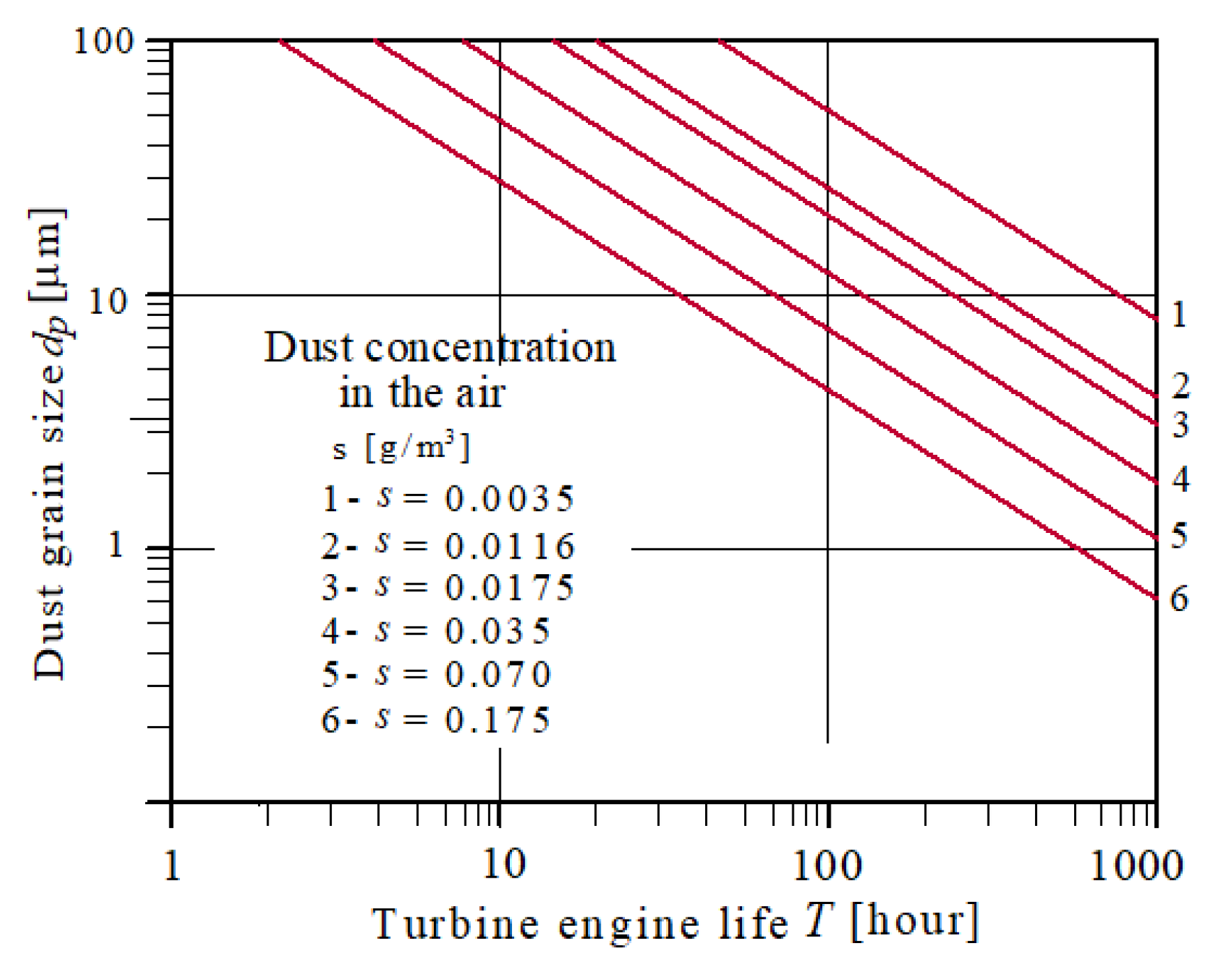
  • Special vehicles (wheeled and tracked) are operated in sandy and off-road areas, where airborne dust concentrations are particularly high, often exceeding 1 g/m³. Helicopters, during takeoff (landing) on a random landing site in sandy terrain, create a dust cloud with dust concentrations reaching up to 3.5 g/m³, significantly reducing visibility and impeding control, potentially leading to disaster.
  • Turbine engines, for proper operation, draw in large airflows (Boeing CH-47 - 39,600 m³/h), and therefore dust – 1.65 kg of dust per minute at an airborne dust concentration of 2.5 g/m³. The intake airflow for a 700 kW tracked vehicle engine is 3500 m3/h, while the dust mass drawn in with the air is several times smaller, at approximately 0.057 kg per minute.
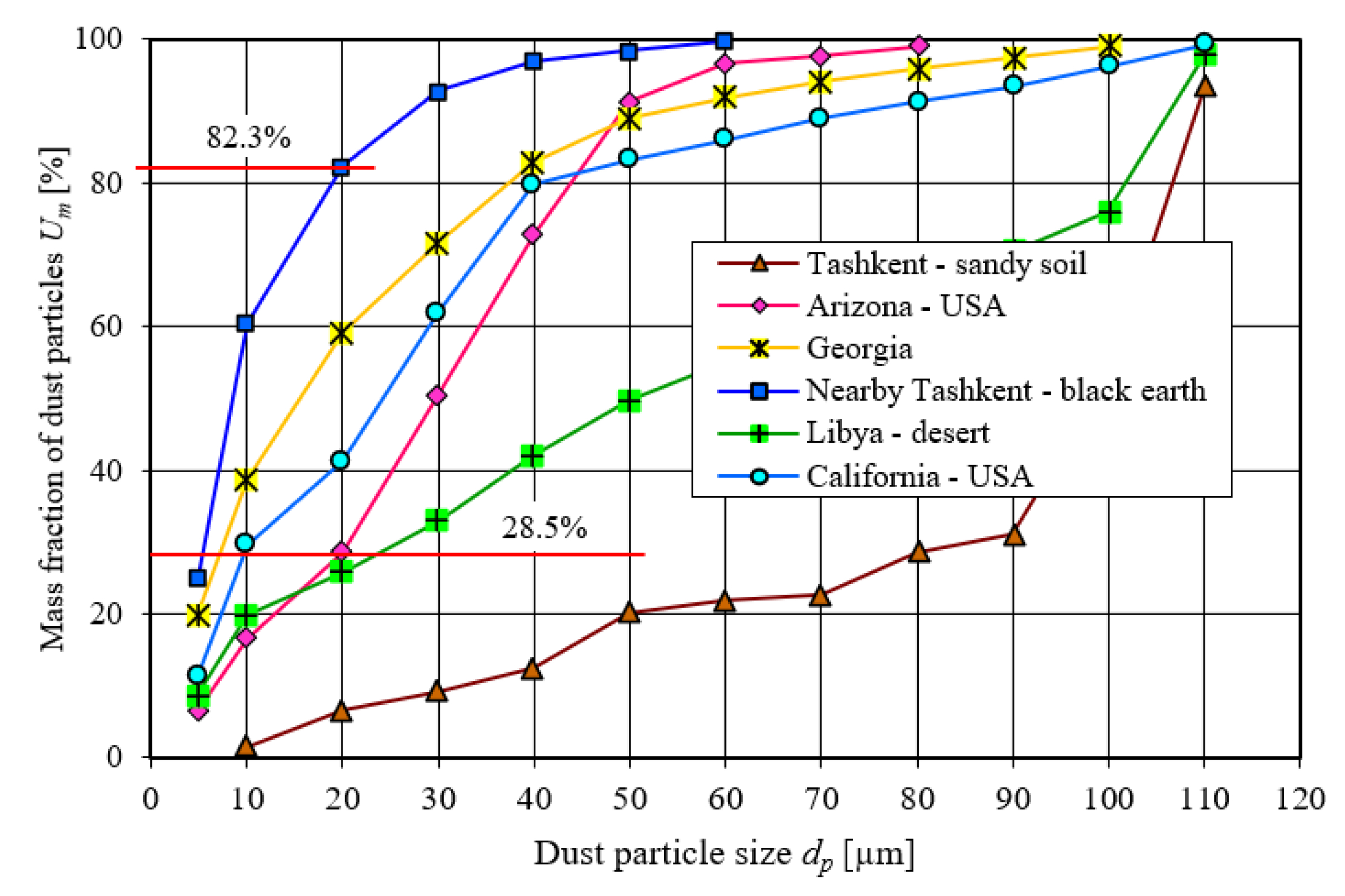
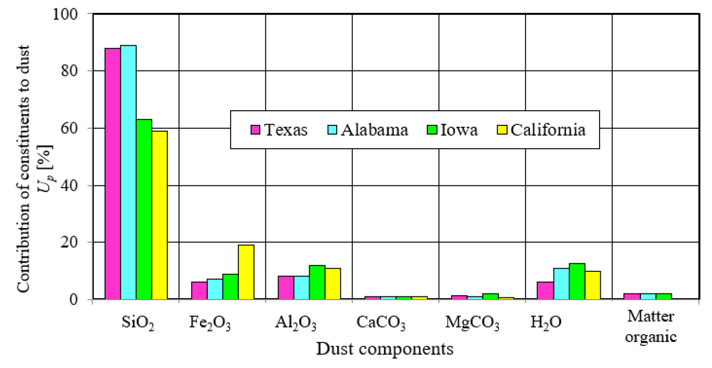
  • Mineral dust grains are characterized by high hardness (7-9 on the Mohs scale) and irregular shapes, which have a destructive effect on engine components, causing accelerated wear. Silica SiO2 and corundum Al2O3 grains are particularly dangerous, with their mass fraction in the dust reaching 60-95%. This reduces the engine’s operating efficiency and limits its durability and reliability.
  • In piston engines, excessive abrasive wear caused by mineral dust primarily affects the T-PR-C connection, which results in increased leakage in the piston head space, and consequently, a decrease in filling and engine power, as well as an increase in specific fuel consumption and exhaust opacity.
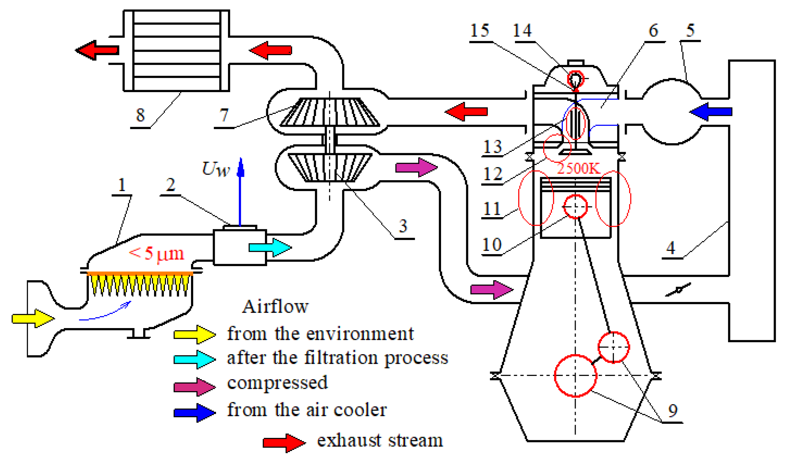
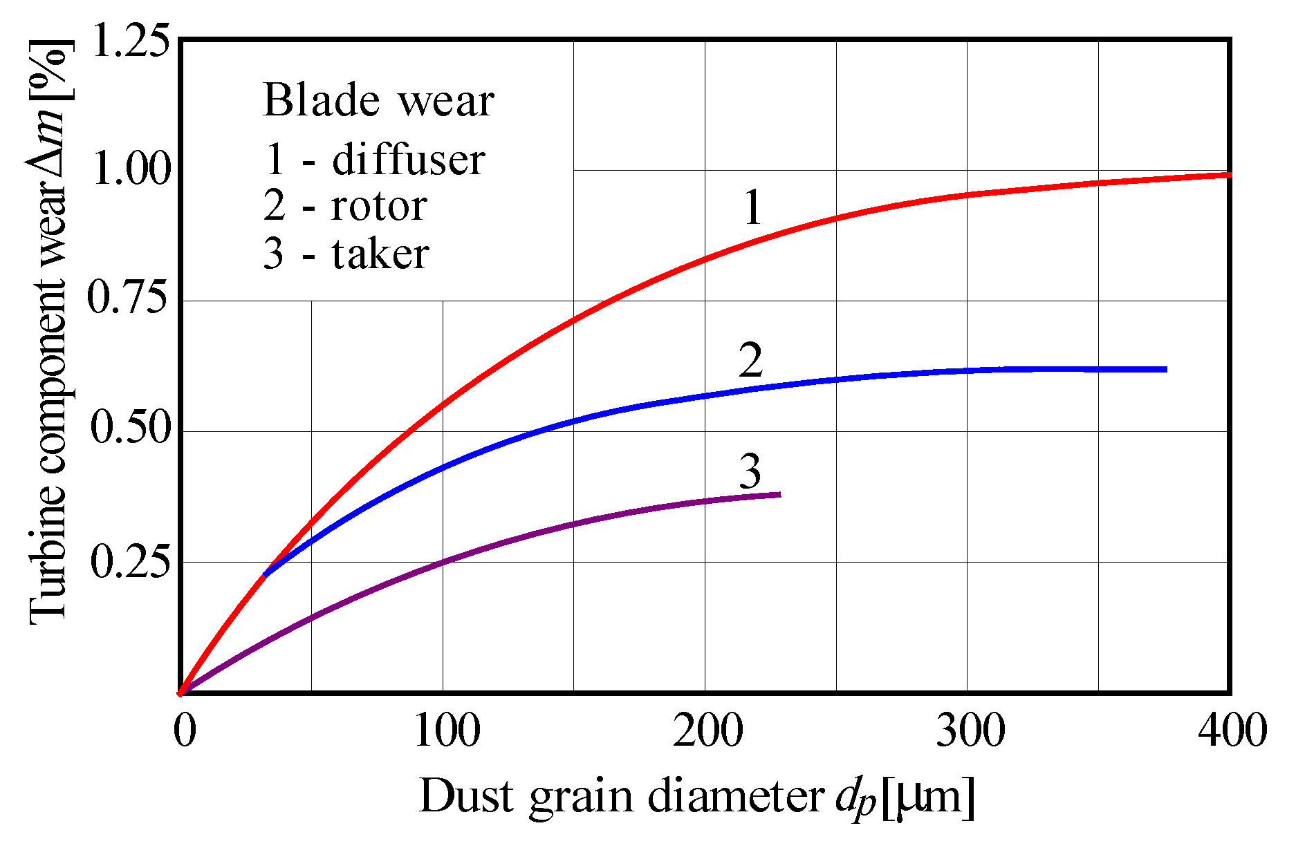
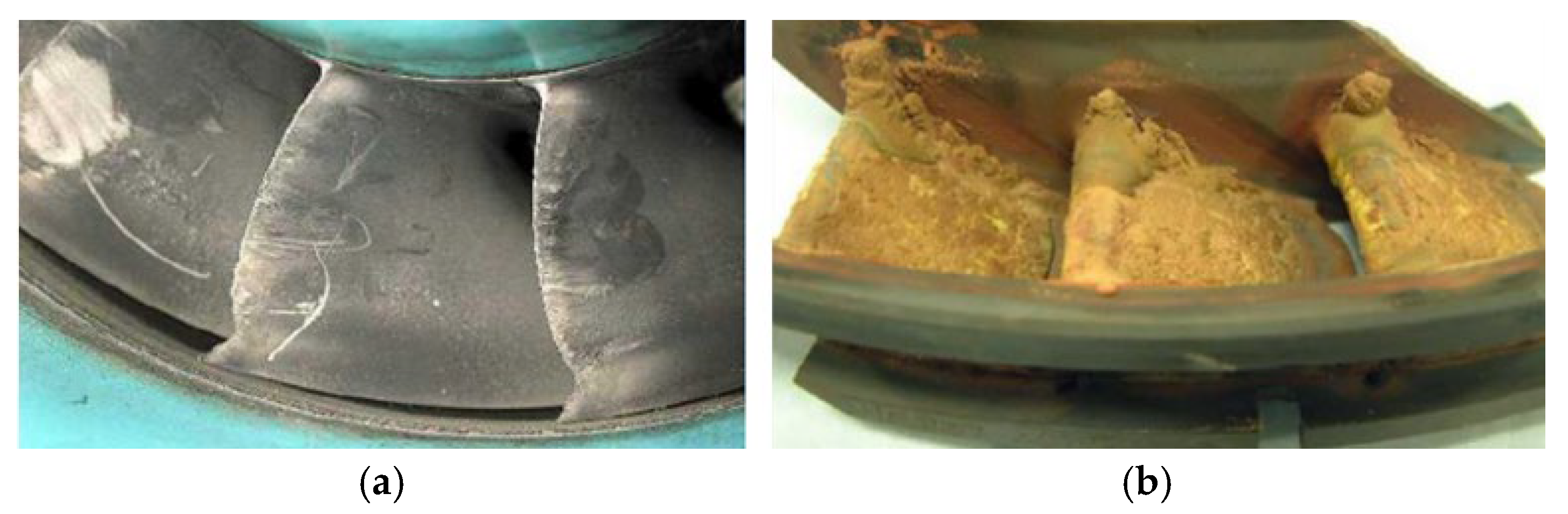
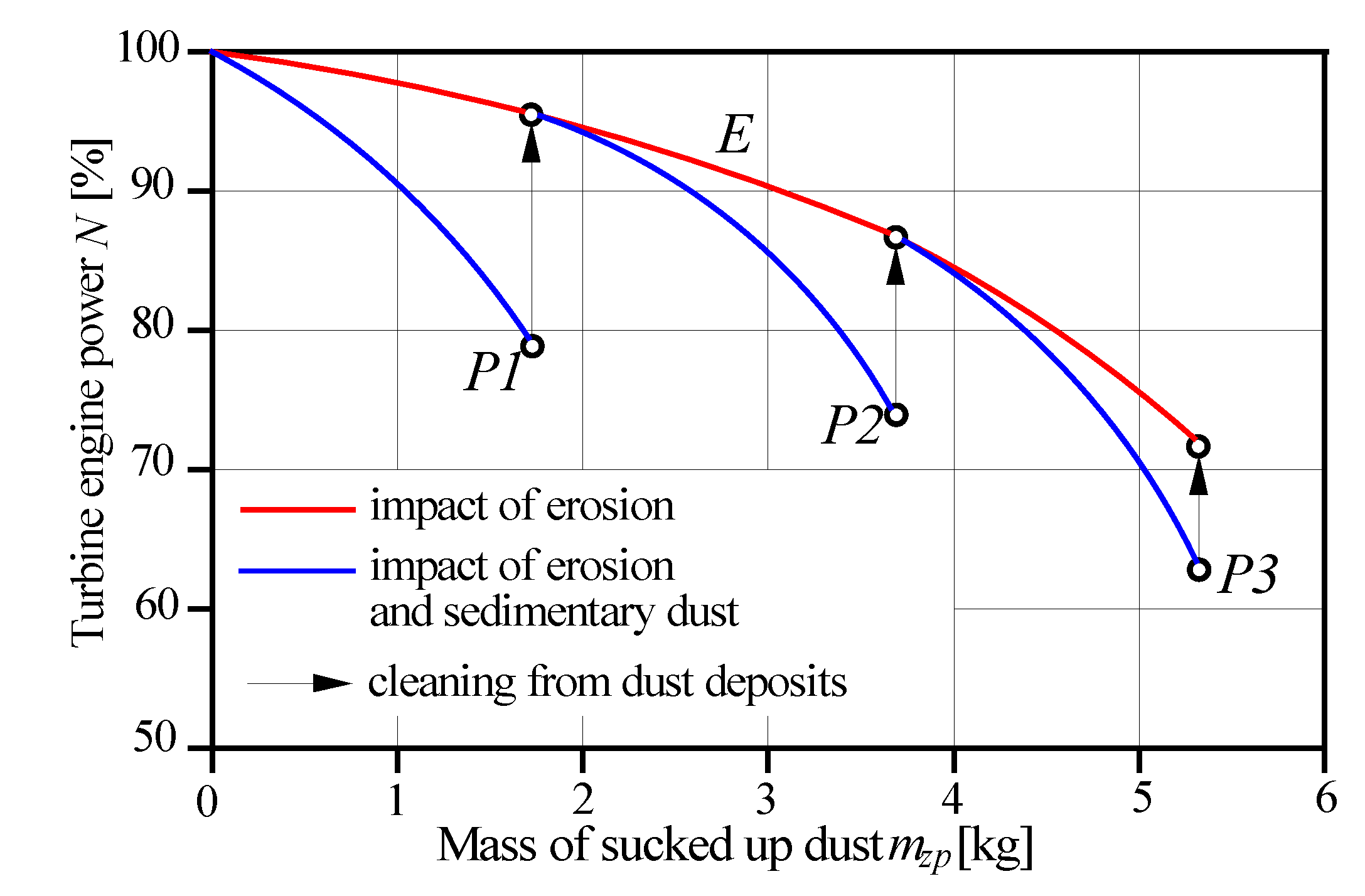
  • In turbine engines, the primary effect of dust grains is accelerated erosive wear of individual parts and entire engine assemblies due to the high peripheral speeds of the rotor assemblies (200-500 m/s) and the deposition of dust deposits (molten contaminants) on the combustion chamber walls and turbine blades. Both effects simultaneously result in a deterioration of power, fuel consumption, and oil consumption characteristics.
  • Erosive wear is a long-term phenomenon, while the accumulation of deposits on the first-stage engine blades and combustion chamber walls is a sudden phenomenon caused by high dust concentrations in the air intake despite the short duration of engine operation under such conditions. The cross-sectional area of the duct decreases, resulting in reduced airflow and engine stalling. This situation is common in helicopter engines during takeoff or landing on an unavoidable landing site, as well as in passenger aircraft that may come into contact with a volcanic ash cloud. There have been reports of tragic helicopter engine failures caused by ingesting excessive amounts of ash.
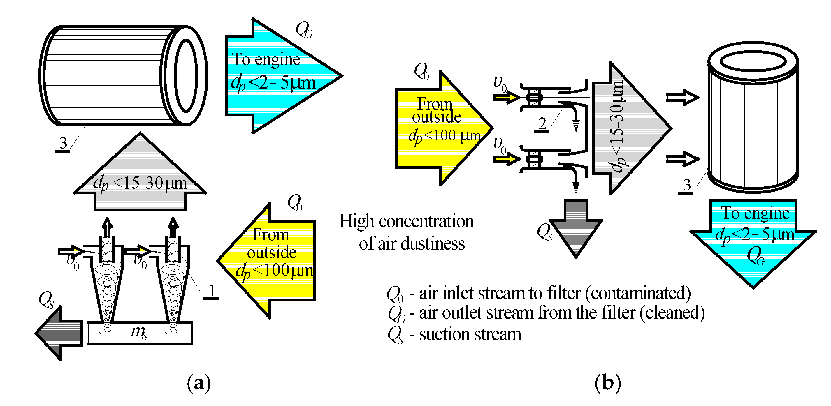
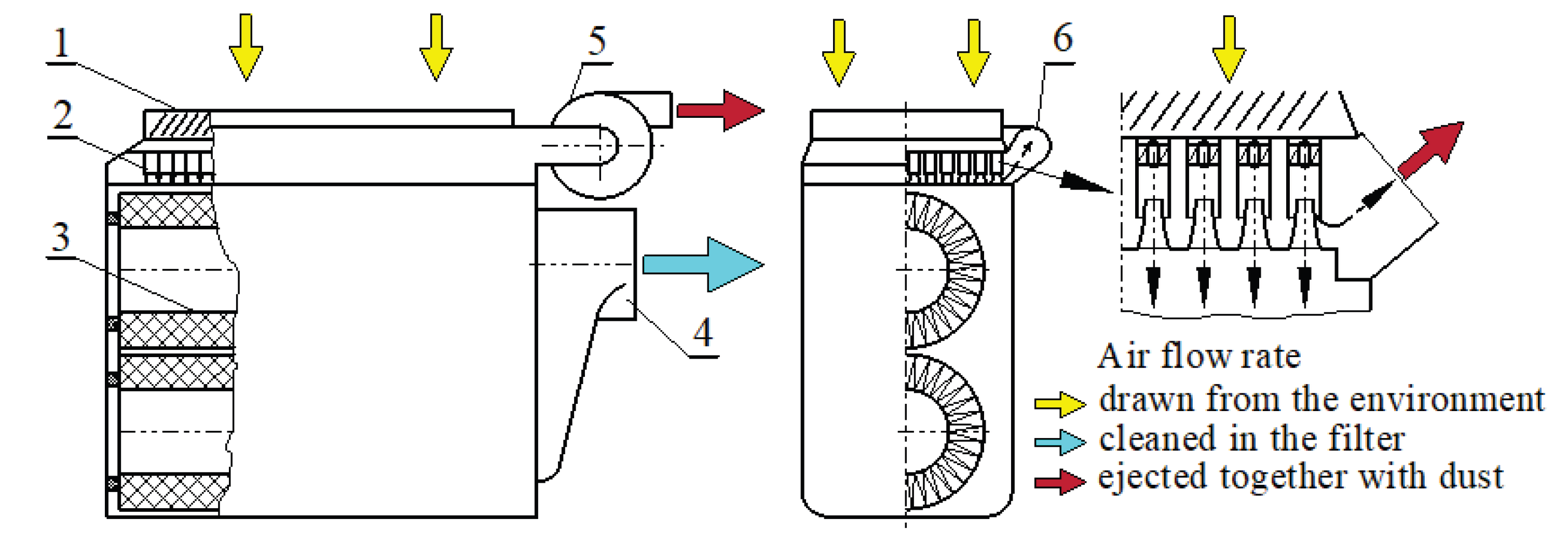
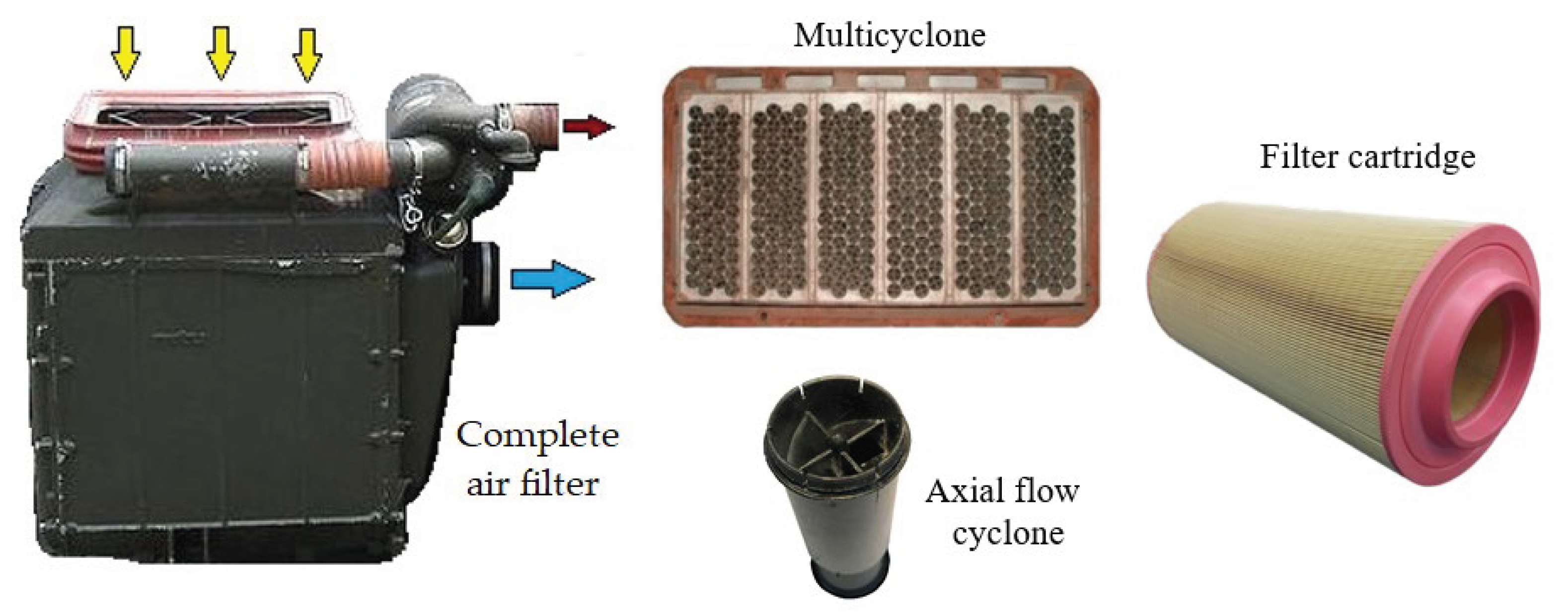
  • Internal combustion engines of motor vehicles are protected from the harmful effects of mineral dust contained in the intake air by using two-stage filtration systems. The first filtration stage is a set of tangential or through-flow cyclones, and the second is a series-arranged porous barrier in the form of a pleated filter paper insert. The two-stage system ensures extended service life but is limited by achieving permissible pressure drop and high accuracy (above 2-5 µm) of the engine intake air.
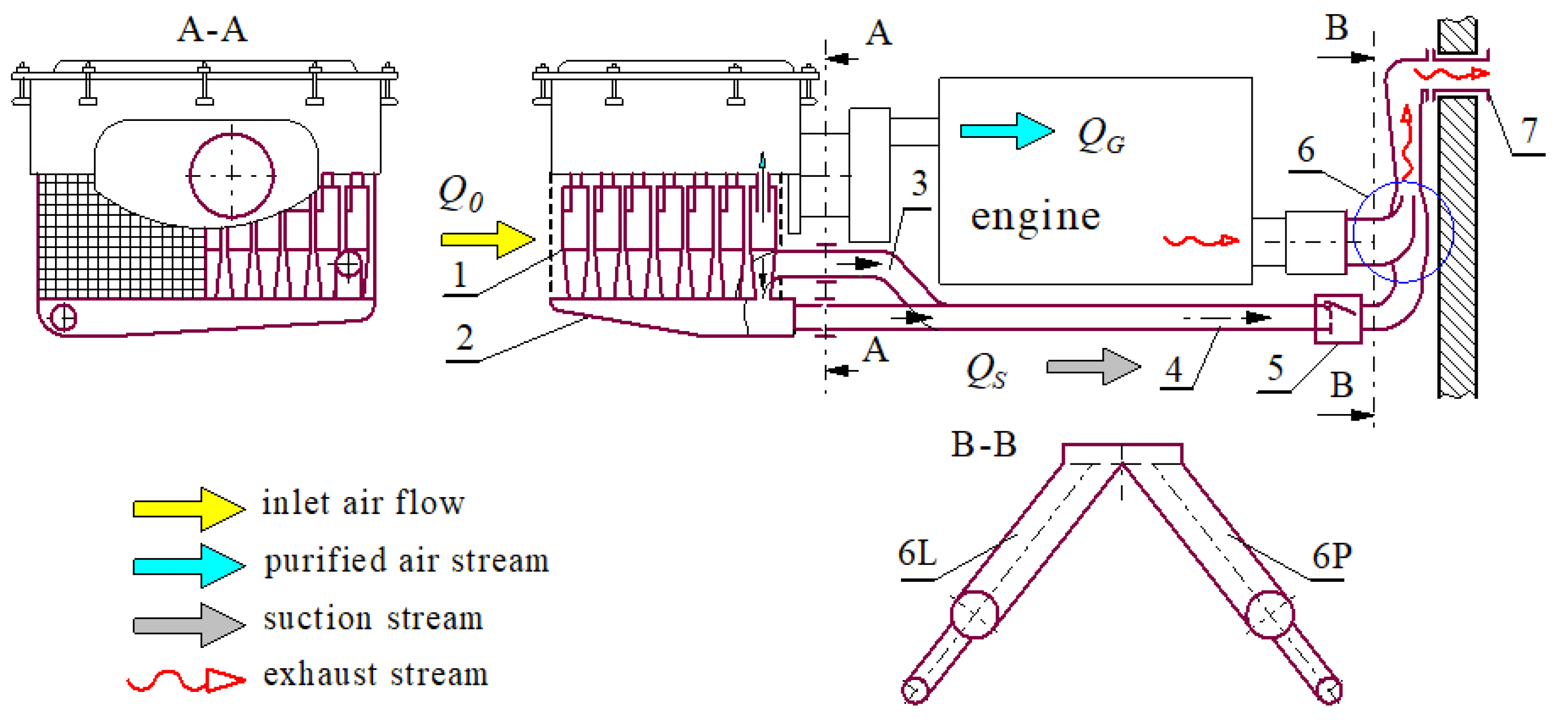
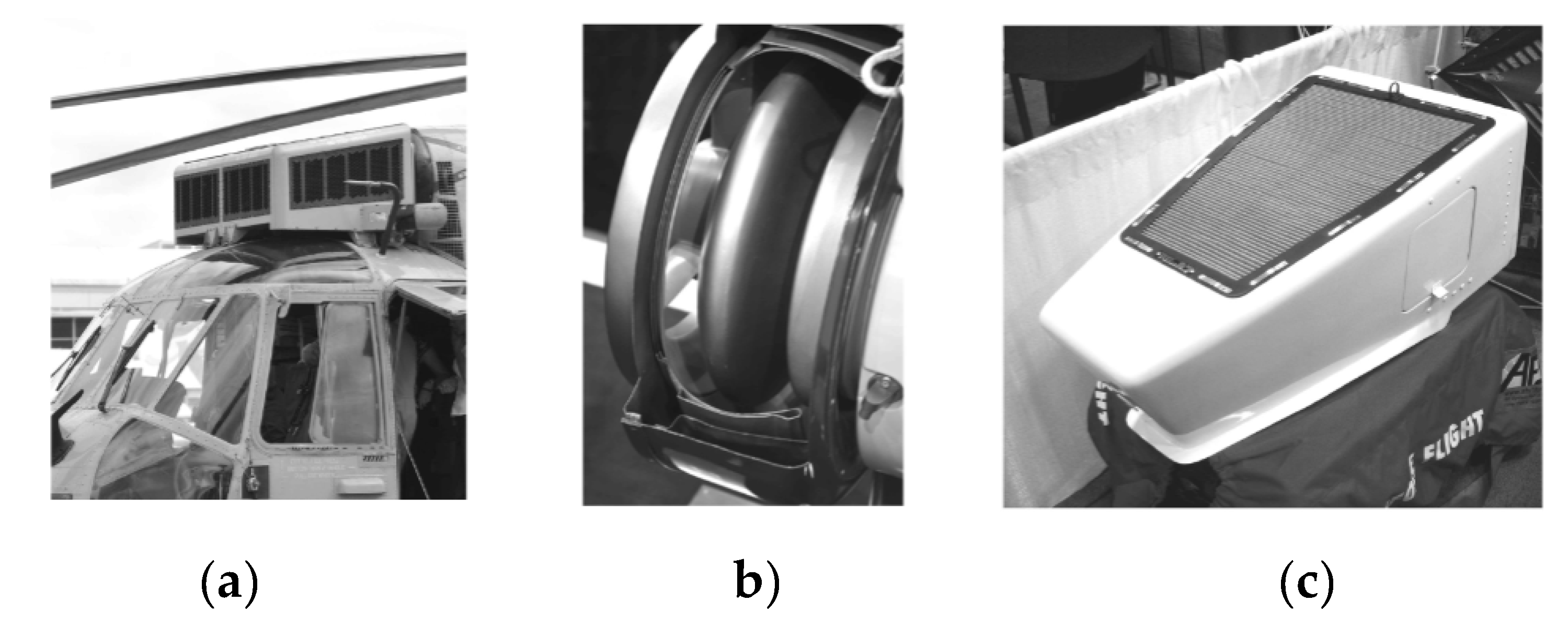
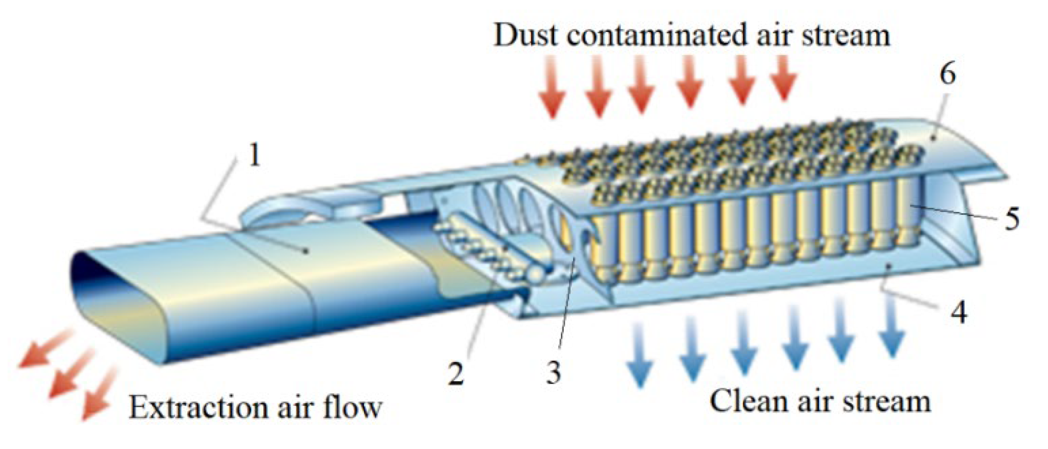
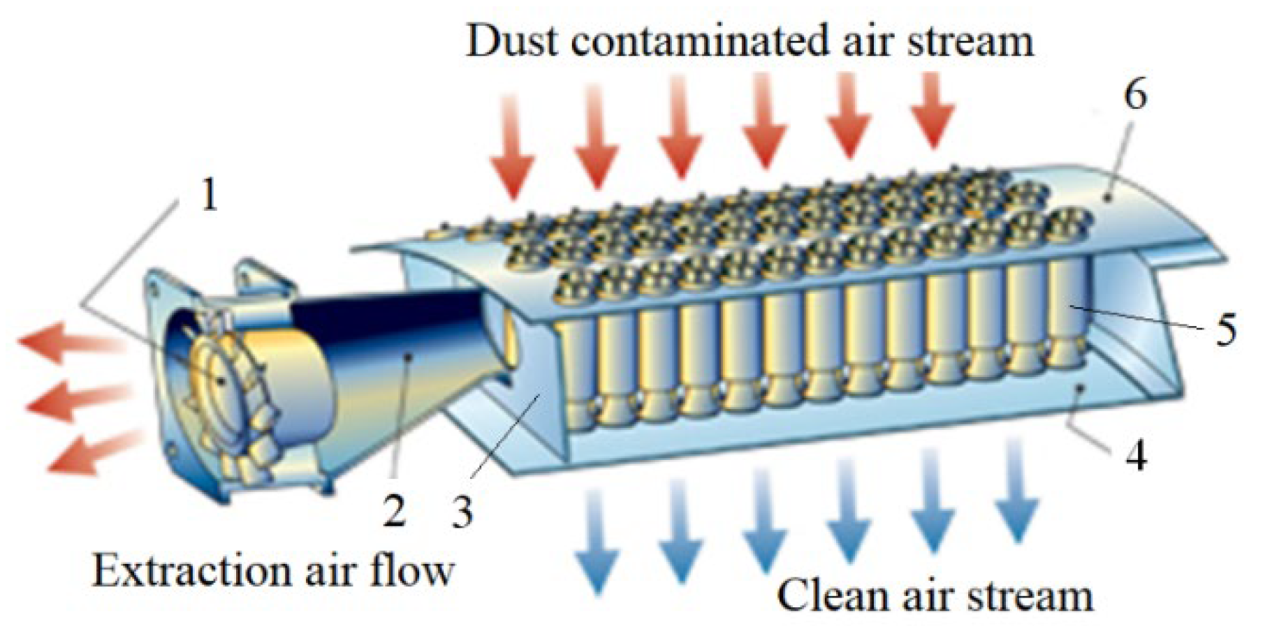
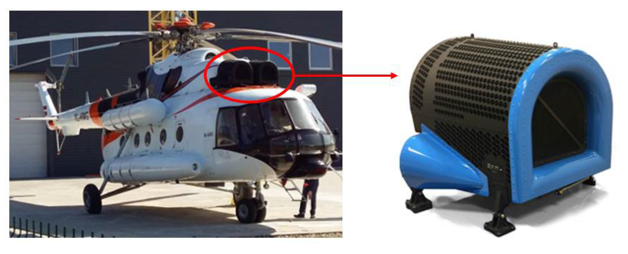
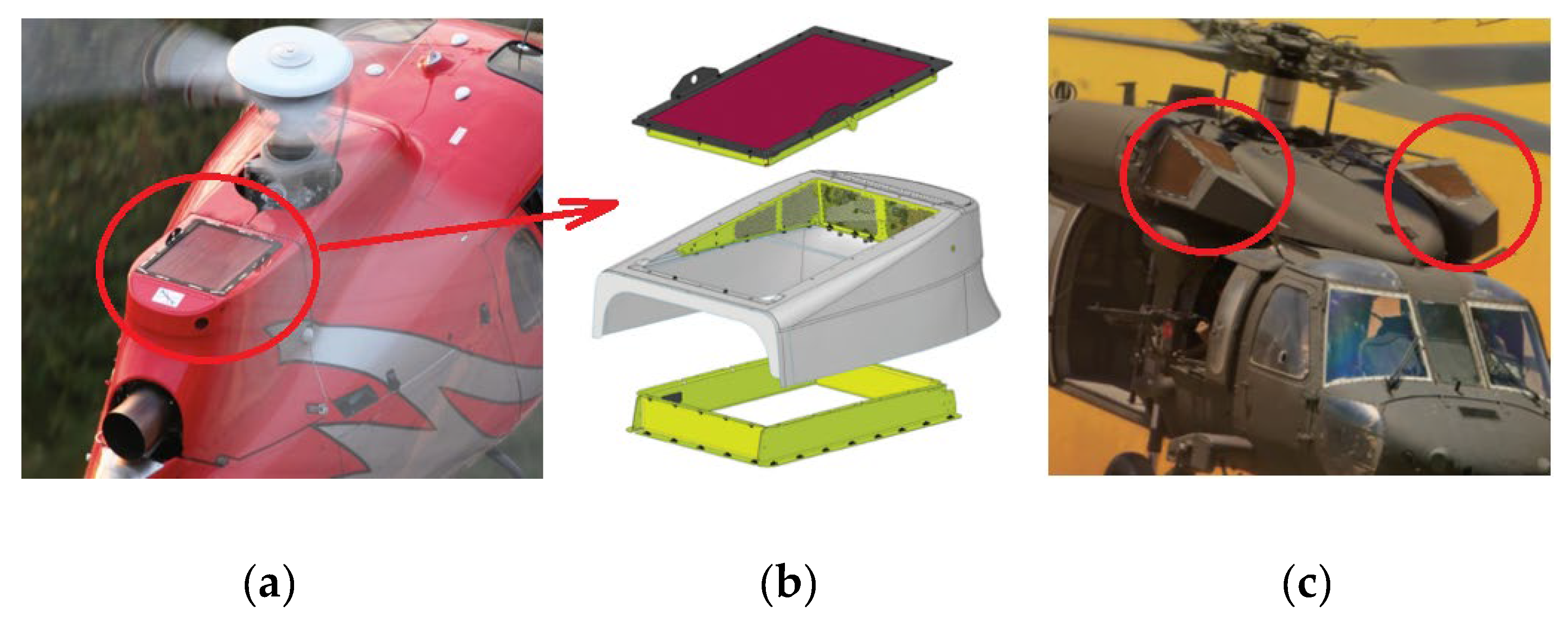
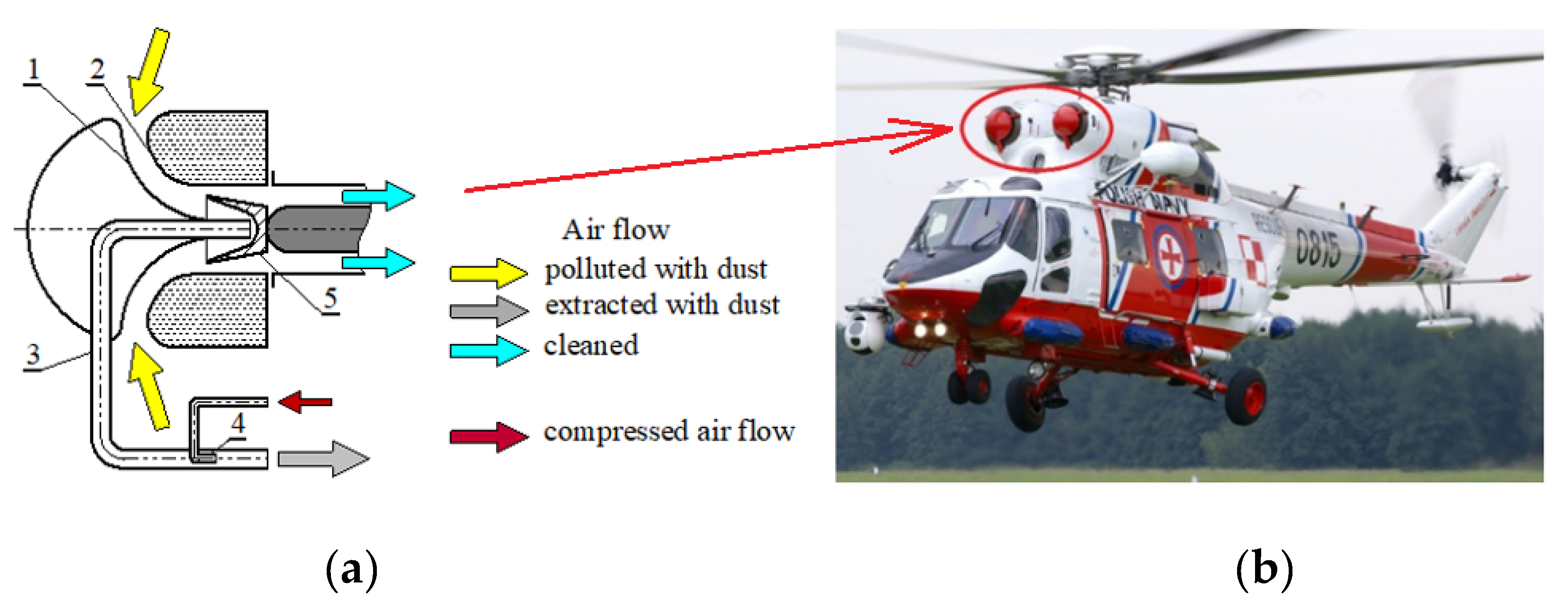
  • To protect helicopter engines from ingesting contaminated air and extending their service life, pipe separators (VTS), inlet barrier filters (IBF), and particle separators (IPS) are used. These devices, collectively referred to as Engine Air Particle Separation (EAPS), can be used individually or in a two-stage system, significantly increasing filtration efficiency and accuracy.
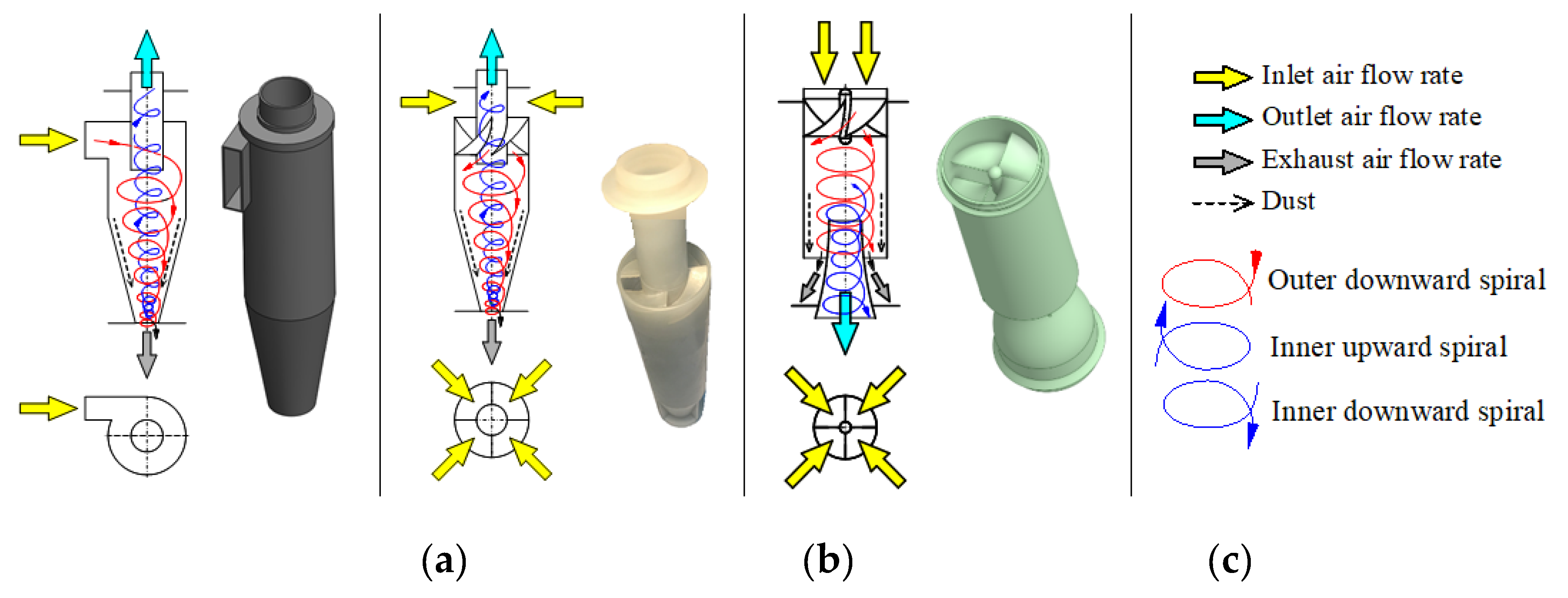
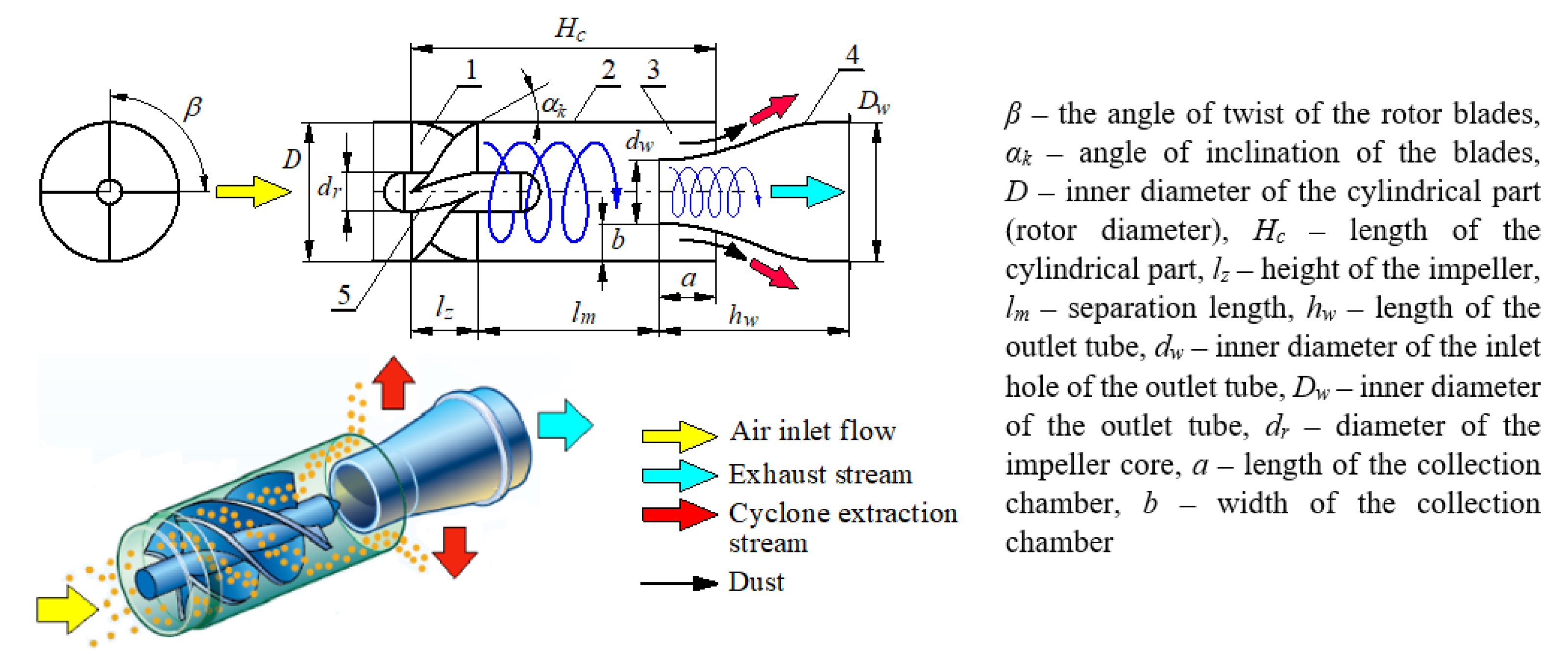
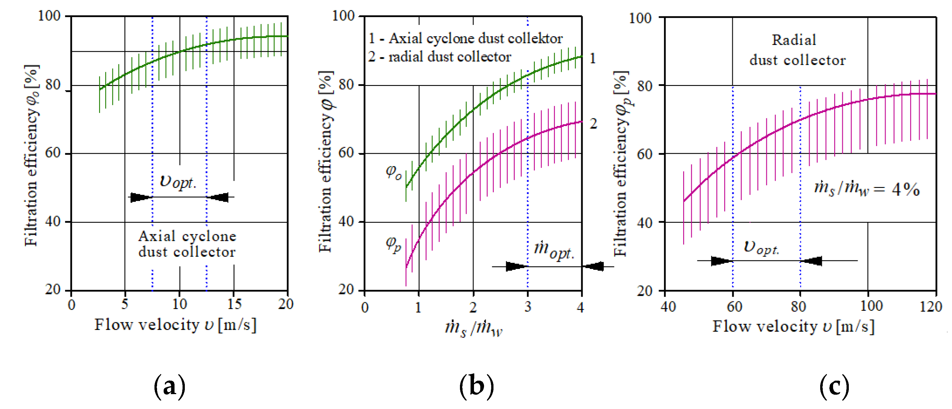
  • Tubular separators (VTS) are constructed from several hundred individual cyclones with an axial inlet of uniform diameter, typically no more than 40 mm, arranged parallel to each other offer many advantages, including: low pressure drop, maintenance-free due to automatic (ejector) dust removal, and protection against ice, snow, heavy rain, and salt spray. The VTS device generates additional pressure drop during flight because it is an externally installed device and requires a large surface area to accommodate the appropriate number of cyclones and ensure the required minimum inlet velocity. The VTS device itself provides low pressure drop and filtration efficiency ranging from 86 to 91%.
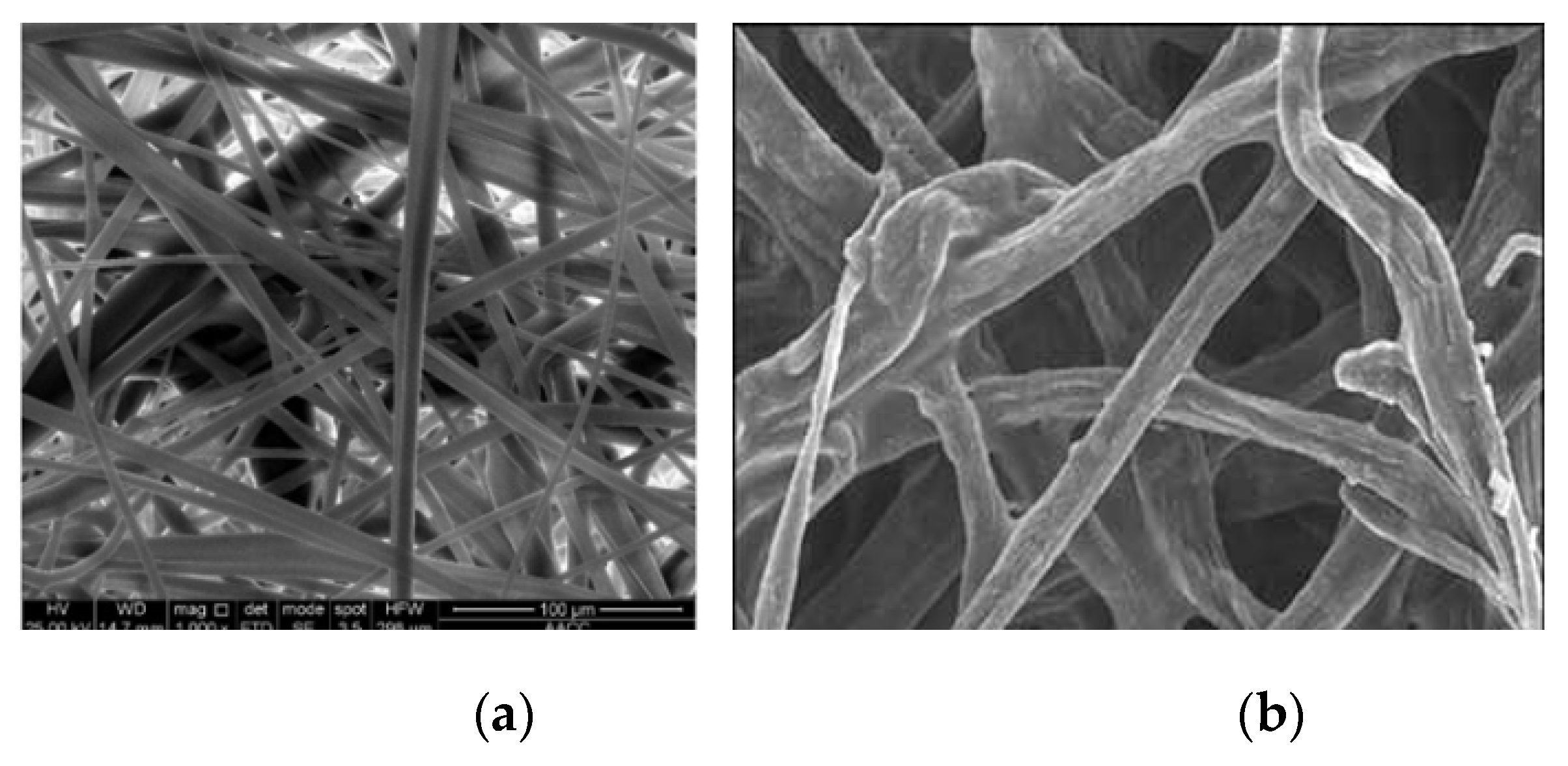
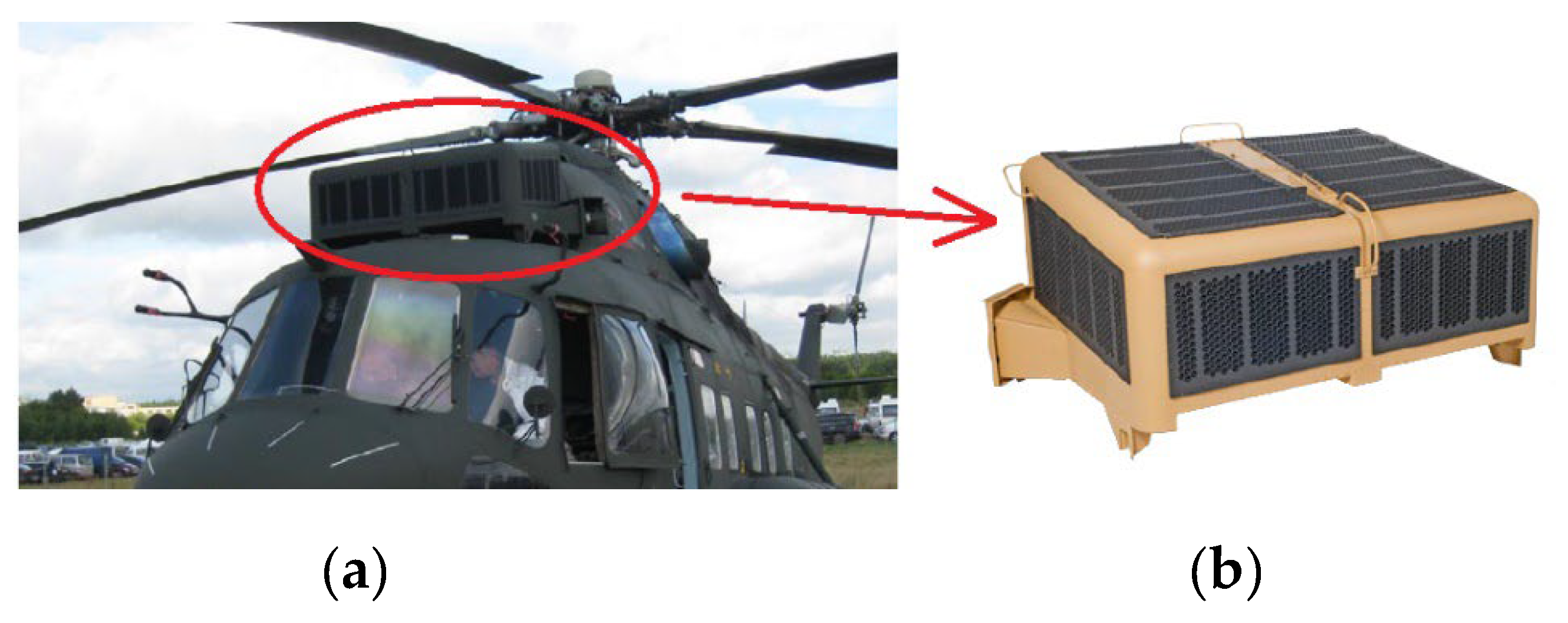
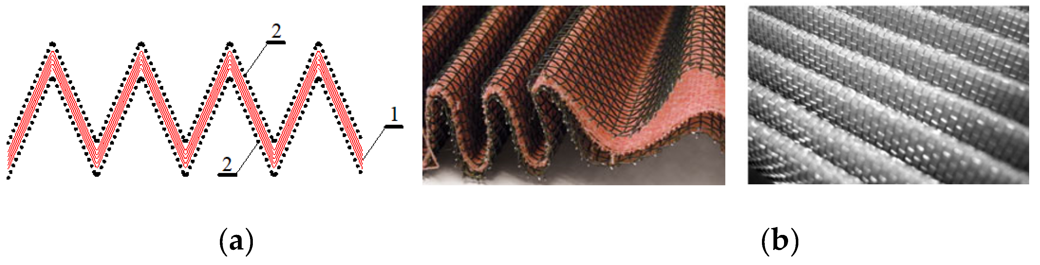
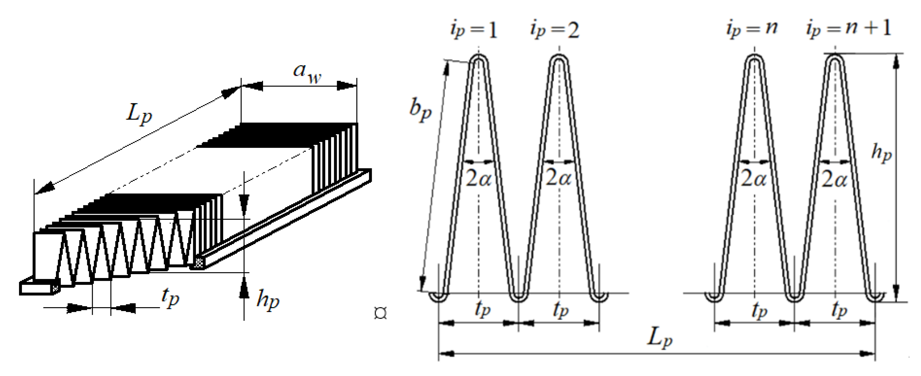
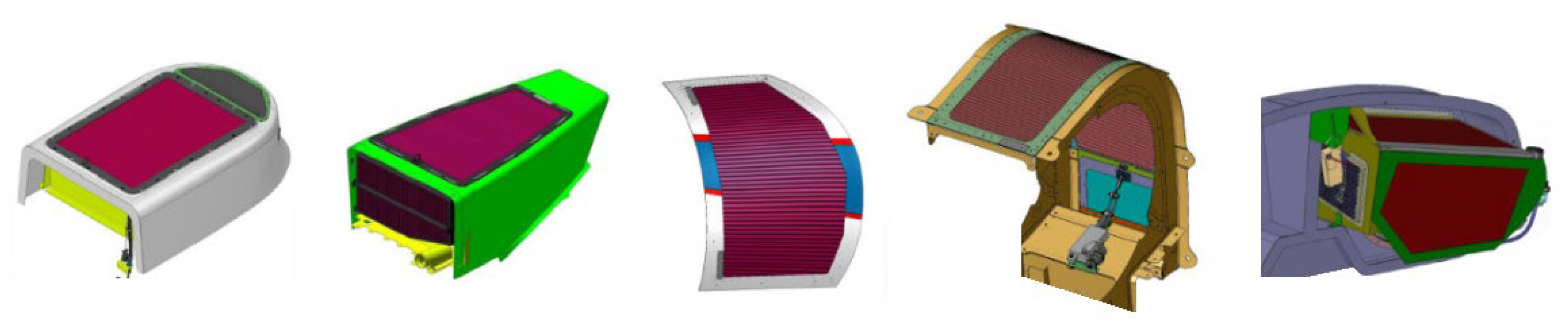
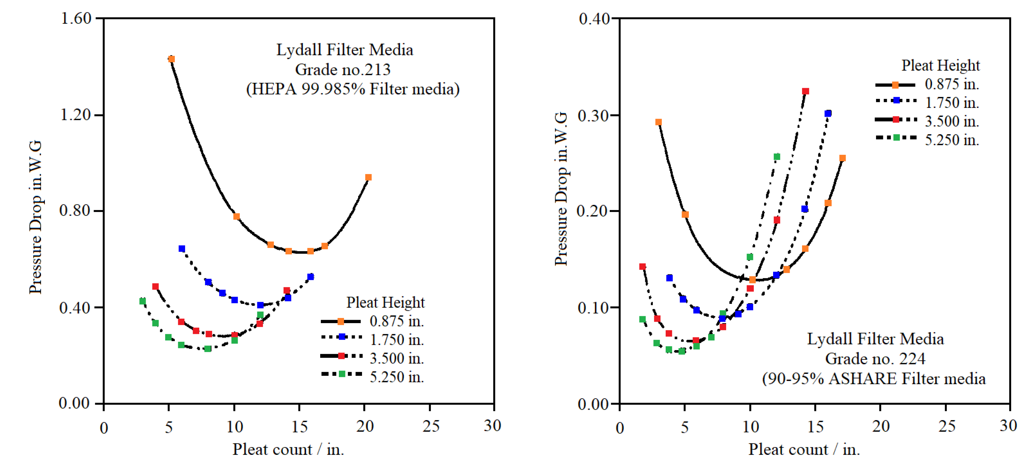
  • The basic element of the filter system (IBF) is a panel, where the filter medium is a multi-layer pleated cotton or cotton-synthetic nonwoven fabric impregnated with special preparation and reinforced with metal mesh on both sides. The IBF ensures low pressure drop and very high filtration efficiency, ranging from 99.3% to 99.9%. Optimizing pleat geometry to reduce pressure drop is crucial.
  • Dust accumulation on the filter element causes a continuous pressure drop, which reduces the airflow to the engine. When the pressure drop reaches a predetermined limit during flight, the bypass (safety) valve opens, allowing air to flow into the engine. However, the engine is then exposed to solid mineral contaminants drawn in from the ambient air.
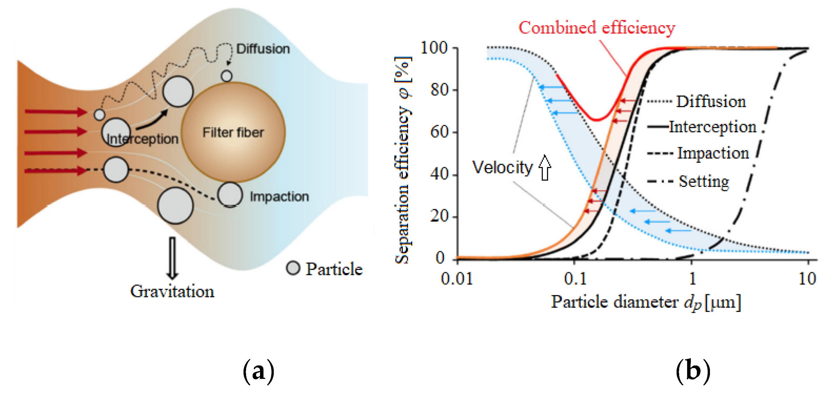
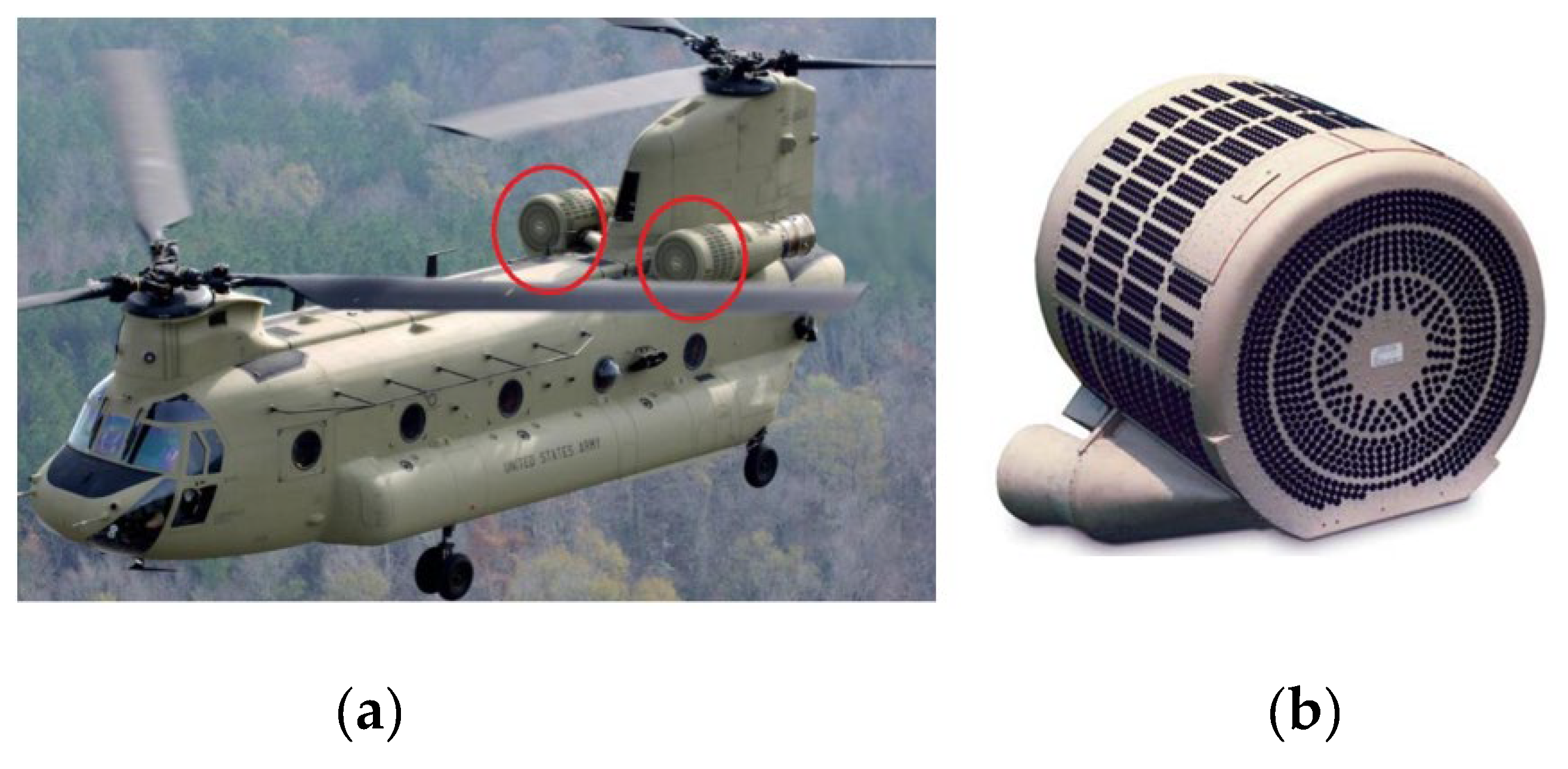
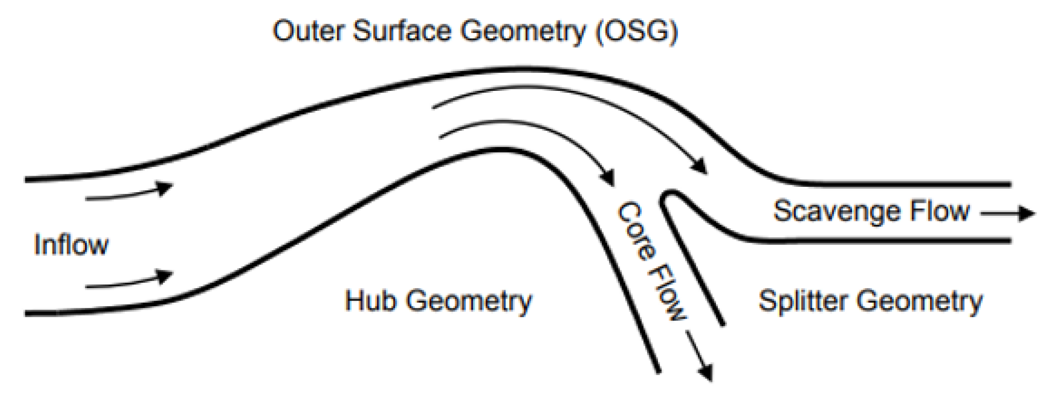
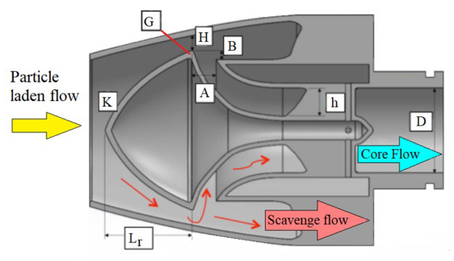
  • The IPS filtration system is an air filtration system integrated with the turbine engine. It is characterized by a compact design, low external resistance, and requires no periodic maintenance. However, it has lower separation efficiency (approximately 75-86%) than the VTS and IBF systems. Improved filtration efficiency is achieved through the use of hybrid VTS-IPS and VTS-IBF devices, which achieve efficiency of up to 99% for particles with a diameter exceeding 20 μm and ensure a less pronounced increase in pressure drop, extending the service life of the filtration system.

Funding

Please add: This research received no external funding.

Data Availability Statement

Data are contained within the article.

Conflicts of Interest

The author declare no conflicts of interest.

Abbreviations

The following abbreviations are used in this manuscript:
P-PR-C Piston-Piston Rings-Cylinder
BDC Bottom Dead Center
EAPS Engine Air Particle Separation
VTS Vortex Tube Separators
IBF Inlet Barrier Filters
IPS Inertial Particle Separators

References

  1. Van der Walt, J.P.; Nurick, A. Erosion of dust-filtered helicopter turbine engines part I: basic theoretical considerations, Journal of Aircraft 1995, 32(1), 106-111. [CrossRef]
  2. Van der Walt, J.P.; Nurick, A. Erosion of dust-filtered helicopter turbine engines part II: erosion reduction. Journal of Aircraft 1995, 32(1), 112-117. [CrossRef]
  3. Honeywell AGT1500 - Archived 3/2009. https://www.forecastinternational.com/archive/disp_pdf.cfm?DACH_RECNO=180.
  4. Schaeffer, J.W.; Olson, L.M. Air Filtration Media for Transportation Applications. Filtration & Separation 1998, 35(2), 124-129.
  5. Jaroszczyk, T.; Pardue, B.A.; Heckel, S.P., Kallsen, K.J. Engine air cleaner filtration performance – theoretical and experimental background of testing. Presented at the AFS Fourteenth Annual Technical Conference and Exposition, May 1, 2001, Tampa, Florida. Included in the Conference Proceedings (Session 16).
  6. Pinnick, R.G.; Fernandez, G.; Hinds, B.D.; Bruce, C.W.; Schaefer, K.W.; Pendelton, J.D. Dust Generated by Vehicular Traffic on Unpaved Roadways: Sizes and Infrared Extinction Characteristics. Aerosol Sci. Technol. 1985, 4, 99-121. [CrossRef]
  7. Barbolini, M.; Di Pauli, F.; Traina. M. Simulation of air filtration for the determination of filter elements. MTZ - Motortechnische Zeitschrift 2016, 5(12), 24-28. [CrossRef]
  8. Dziubak, T. Zapylenie powietrza wokół pojazdu terenowego. Wojskowy Przegląd Techniczny 1990, 3(257), 154-157. (in Polish).
  9. Dziubak, T. Research into a Two-Stage Filtration System of Inlet Air to the Internal Combustion Engine of a Motor Vehicle. Energies 2024, 17, 6295. [CrossRef]
  10. Rybak, P.; Hryciów, Z.; Michałowski, B.; Wiśniewski, A. Assessment of the Impact of Wear and Tear of Rubber Elements in Tracked Mechanism on the Dynamic Loads of High-Speed Tracked Vehicles. Acta Mechanica et Automatica 2023, 17(1). [CrossRef]
  11. Bojdo, N. Rotorcraft engine air particle separation. A thesis submitted to the University of Manchester for the degree of Doctor of Philosophy in the Faculty of Engineering and Physical Sciences 2012. https://www.escholar.manchester.ac.uk/uk-ac-man-scw:183545.
  12. Szczepankowski, A.; Szymczak, J.; Przysowa, R. The Effect of a Dusty Environment Upon Performance and Operating Parameters of Aircraft Gas Turbine Engines, Conference: Specialists’ Meeting - Impact of Volcanic Ash Clouds on Military Operations NATO AVT-272-RSM-047 At: Vilnius. May 2017. [CrossRef]
  13. Taslim, M.E.; Spring, S. A Numerical study of sand particle distribution, density, and shape effects on the scavenge efficiency of engine inlet particle separator system, Journal of the American Helicopter Society. 2010, 55(2), 022006. [CrossRef]
  14. Stallard, P. Helicopter engine protection. Perfusion. 1997, 12(4), 263-267. [CrossRef]
  15. Jaroszczyk, T.; Fallon, S.L; Liu, Z.G.; Heckel, S.P. Development of a Method to Measure Engine Air Cleaner Fractional Efficiency. International Congress and Exposition Detroit, Michigan March 1-4, 1999.
  16. Needelman, W.M.; Madhaven, P.V. Review of Lubricant Contamination and Diesel Engine Wear, SAE Technical Paper 881827. 1988, 1-15. [CrossRef]
  17. Diesel Engine Air Filtration. Pall Aerospace, Europa House. 1999.
  18. Dziubak, T.; Dziubak, S.D. A Study on the Effect of Inlet Air Pollution on the Engine Component Wear and Operation. Energies 2022, 15, 1182. [CrossRef]
  19. Koszałka, G.; Suchecki, A. Changes in performance and wear of small diesel engine during durability test. Combustion Engines 2015, 162(3), 34-40. [CrossRef]
  20. Fitch J. Clean Oil Reduces Engine Fuel Consumption, Practicing Oil Analysis Magazine 11-12, 2002. https://www.machinerylubrication.com/Read/401/oil-engine-fuel-consumption. (Accessed 2 January 2025).
  21. Thomas, J.; West, B.; Huff, S. Effect of Air Filter Condition on Diesel Vehicle Fuel Economy; SAE Technical Paper 2013-01-0311; SAE International: Warrendale, PA, USA, 2013. [CrossRef]
  22. Long J.; Tang M.; Sun Z.; Liang Y.; Hu J. Dust Loading Performance of a Novel Submicro-Fiber Composite Filter Medium for Engine. Materials 2018, 11(10), 2038. [CrossRef]
  23. Maciejewska, A. Krzemionka krystaliczna: kwarc i krystobalit – frakcja respirabilna. Podstawy i Metody Oceny Środowiska Pracy 2014, 4(82), 67-128. https://m.ciop.pl/CIOPPortalWAR/file/75268/20150527112518&5.krzemionka.pdf (Accessed 23 July 2025).
  24. Kurz, R.; Brun, K. Degradation of Gas Turbine Performance in Natural Gas Service. Journal of Natural Gas Science and Engineering 2009, 95-102. [CrossRef]
  25. Szczeciński, S. Odpylanie powietrza wlotowego. Wojskowy Przegląd Techniczny 1983, 5-6, 236-241.
  26. Melino, F.; Morini, M.; Peretto, A.; Pinelli, M.; Spina, P.R. Compressor fouling modeling: relationship between computational roughness and gas turbine operation time. J. Eng. Gas Turbines Power 2012, 134 (5) 1-8. [CrossRef]
  27. Alqallaf, J.; Teixeira, J.A. Numerical study of effects of solid particle erosion on compressor and engine performance. Results in Engineering 2022, 15, 100462. [CrossRef]
  28. Tabakoff, W.; Hamed, A.; Shanov, V. Blade deterioration in a gas turbine engine. Int. J. Rotating Mach. 1998, 4(4), 233-241. [CrossRef]
  29. Hamed, A.; Tabakoff, W.C.; Wenglarz, R.V. Erosion and deposition in turbomachinery. J. Propul. Power 2006, 22(2), 350-360. [CrossRef]
  30. Dzierżanowski, P.; Kordziński, W.; Otyś, J.; Szczeciński, S.; Wiatrek, R. Napędy Lotnicze. Turbinowe silniki śmigłowe i śmigłowcowe. WKŁ Warszawa, 1985, Poland.
  31. Bojdo, N.; Filippone, A. Operational Performance Parameters of Engine Inlet Barrier Filtration Systems for Rotorcraft. Conference: American Helicopter Society 67th Annual Forum, Virginia Beach, VA, May 3-5, 2011. https://www.researchgate.net/publication/266087797.
  32. Hamed, A.; Tabakoff, W.; Wenglarz, R. Erosion and deposition in turbomachinery. Journal of Propulsion and Power. 2006, 22(2). [CrossRef]
  33. Filippone, A.; Bojdo, N. Turboshaft Engine Air Particle Separation. Progress in Aerospace Sciences. 2010, 46(5), 224-245. [CrossRef]
  34. Kozakiewicz, A. Analiza uszkodzeń turbinowych silników odrzutowych, Prace Instytutu Lotnictwa 2011, 213, 224-234.
  35. Balicki, W.; Chachurski, R.; Kozakiewicz, A.; Głowacki, P.; Szczeciński, J.; Szczeciński, S. Problematyka filtracji powietrza wlotowego do turbinowych silników śmigłowych. Prace Instytutu Lotnictwa 2009,199(4), 25-30.
  36. Fatal MV-22 crash in Hawaii linked to excessive debris ingestion. https://www.flightglobal.com/news/articles/fatal-mv-22-crash-in-hawaii-linked-to-excessivedebr-419484/ (Accessed 28 November, 2024).
  37. Tabakoff, W.; Hamed, A. Installed engine performance in dust-laden atmosphere. Aircraft Design Systems and Operations Meeting. October 31-November 2, 1984/San Diego, California. [CrossRef]
  38. Przedpelski, Z.J.; Casadevall, T.J. Impact of Volcanic Ash from 15 December 1989 Redoubt Volcano Eruption on GE CF6-80C2 Turbofan Engines. In Volcanic Ash and Aviation Safety: Proceedings of the First International Symposium on Volcanic Ash and Aviation Safety, U.S. Geological Survey Bulletin 1994, 2047, 129-135. https://www.researchgate.net/publication/237216295.
  39. Chen, X.; Yu, J.; Zhang, Y. The use of axial cyclone separator in the separation of wax from natural gas: A theoretical approach. Energy Reports 2021, 7, 2615-2624. [CrossRef]
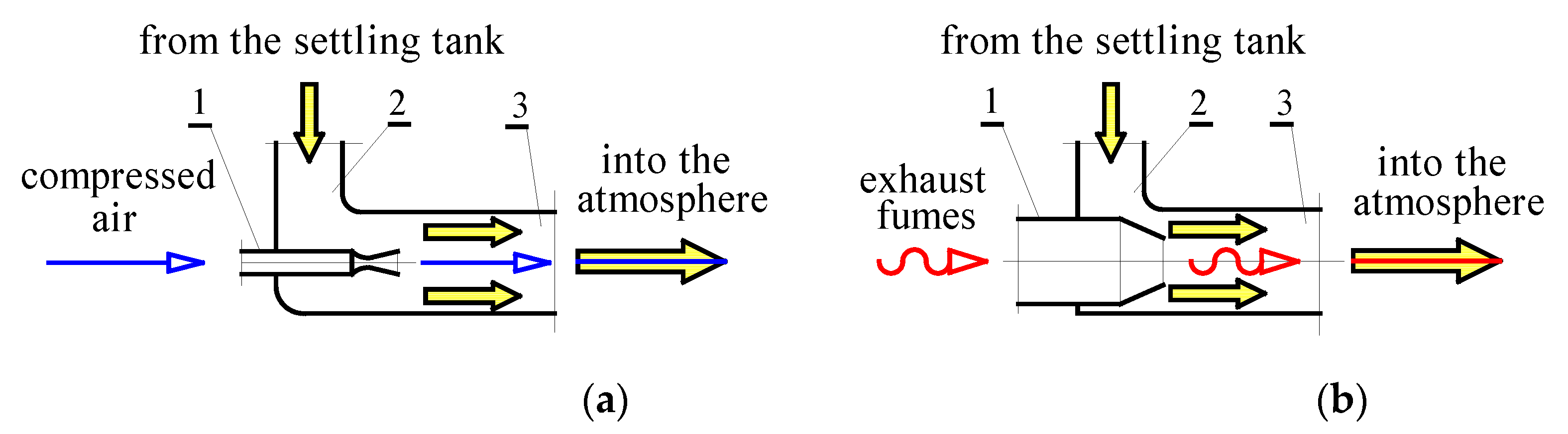
  40. Dziubak, S,; Małachowski, J.; Dziubak, T.; Tomaszewski, M. Numerical studies of an axial flow cyclone with ongoing removal of separated dust by suction from the settling tank, Chem. Eng. Res. Des. 2024, 208, 29-51. [CrossRef]
  41. Dziubak, T., Problems of dust removal from multi-cyclones of engine air cleaners in cross-country motor vehicles. Arch. Automot. Eng. – Archiwum Motoryzacji 2017, 76(2), 37-62. [CrossRef]
  42. Dzierżanowski, P.; Dziubak, T. Możliwości wykorzystania strumienia spalin wylotowych silnika tłokowego do odsysających układów ejekcyjnych odpylaczy bezwładnościowych powietrza wlotowego, Międzynarodowa konferencja KONES ’96, Zakopane 11-14.09.1996. Poland.
  43. Dziubak, T.: Problemy odsysania pyłu z multicyklonu filtru powietrza silnika pojazdu mechanicznego eksploatowanego w warunkach dużego zapylenia powietrza. Zagadnienia Eksploatacji Maszyn PAN 2001, 1(125).
  44. Teng, G.; Shi, G.; Zhu, J.; Qi, J. A numerical simulation method for pressure drop and normal air velocity of pleated filters during dust loading. PLoS ONE 2023,18(2), e0282026. [CrossRef]
  45. Jung, S.; Kim, J. Advanced Design of Fiber-Based Particulate Filters: Materials, Morphology, and Construction of Fibrous Assembly. Polymers 2020, 12, 1714. [CrossRef]
  46. Zhu, M.; Han, J.; Wang, F.; Shao, W.; Xiong, R.; Zhang, Q.; Pan, H.; Yang, Y.; Samal, S.K.; Zhang, F.; et al. Electrospun Nanofibers Membranes for Effective Air Filtration. Macromol. Mater. Eng. 2017, 302, 1600353.
  47. Abdolghader, P.; Brochot, C.; Haghighat F.; Bahloul A. Airborne nanoparticles filtration performance of fibrous media: A review. Science and Technology for the Built Environment 2018 24, 648–672. [CrossRef]
  48. Tennal, K.B.; Mazumder, M.K.; Siag, A.; Reddy, R.N. Effect of loading with AIM oil aerosol on the collection efficiency of an electret filter. Particulate Science and Technology 1991, 9(1-2), 19-29. [CrossRef]
  49. Lee, K.; Liu, B. Theoretical study of aerosol filtration by fibrous filters. Aerosol Science and Technology 1982, 1(2):147-161. [CrossRef]
  50. Payet, S.; Boulaud, D.; Madelaine, G.; Renoux, A. Penetration and pressure drop of a HEPA filter during loading with submicron liquid particles. Journal of Aerosol Science 1992, 23(7):723-735. [CrossRef]
  51. Barris, M.A. Total Filtration TM. The Influence of Filter Selection on Engine Wear. Emissions and Performance; SAE Technical Paper: 952557; SAE International: Warrendale, PA, USA, 2018. [CrossRef]
  52. Bugli, N.J.; Green, G.S. Performance and Benefits of Zero Maintenance Air Induction Systems. SAE Technical Paper 2005-01-1139, 2005, 114, 1015–1028. [CrossRef]
  53. Trautmann, P.; Durst, M.; Pelz, A.; Moser, N. High Performance Nanofibre Coated Filter Media for Engine Intake Air Filtration. AFS 2005 Conference and Expo, April 10-13, 2005.
  54. Dziubak, T. Experimental Dust Absorption Study in Automotive Engine Inlet Air Filter Materials. Materials 2024, 17, 3249. [CrossRef]
  55. Guo, Y.; Guo, Y.; He, W.; Zhao, Y.; Shen, R.; Liu, J.; Wang, J. PET/TPU nanofiber composite filters with high interfacial adhesion strength based on one-step co-electrospinning. Powder Technol. 2021, 387, 136–145. [CrossRef]
  56. Long, J.; Tang, M.; Sun, Z.; Liang, Y.; Hu, J. Dust Loading Performance of a Novel Submicro-Fiber Composite Filter Medium for Engine. Materials 2018, 11, 2038. [CrossRef]
  57. Mann-Hummel - wysokowydajne filtry z nanowłókien. https://truckfocus.pl/nowosci/7520/mann-filter-wprowadza-wysokowydajne-filtry-z-nanowlokien. (Accessed on 21 July 2025).
  58. Grafe, T.; Graham, K. Polymeric Nanofibers and Nanofiber Webs: A New Class of Nonwovens. Presented at INTC 2002: International Nonwovens Technical Conference (Joint INDA – TAPPI Conference), Atlanta, Georgia, September 24-26, 2002.
  59. Heikkilä, P.; Sipilä, A.; Peltola, M.; Harlin, A. Electrospun PA-66 Coating on Textile Surfaces. Textile Research Journal 2007, 77(11), 864-870. [CrossRef]
  60. Jaroszczyk, T.; Liu, Z.G.; Schwartz, S.W.; Holm, Ch.E.; Badeau, K.M.; Janikowski E. Direct flow air filters – a new approach to high performance Engine filtration. Presented at Filtech 2005, Wiesbaden, Germany, October 11-13, 2005, Conference Proceedings, Vol. II, 235-243.
  61. Grafe, T.; Googins M.; Barris, M.; Schaefer, J.; Canepa, R. Nanofibers in Filtration Applications in Transportation, Filtration 2001 International Conference and Exposition, Chicago, Illinois, December 3-5, 2001.
  62. Stephenson, C.D.; Shohet, H.N.; Speiden, E.F. CH-54A and CH-53A Engine Air Particle Separator (EAPS) Development, Proceedings of the Seventh Annual National Conference on Environmental Effects on Aircraft and Propulsion Systems, Paper No. 67-ENV-7, Sept. 1967.
  63. Stephenson, C.D. CH-54A Engine Air Particle Separator-3 1/2 Years of Successful Operation. The American Society of Mechanical Engineers. Presentation at the ASME Gas Turbine Conference & Products Show, Brussels, Belgium, May 24-28, 1970.
  64. Ghodbane, S.; Beniaiche, A.; Belkallouche, A.; Janssens, B. Numerical Investigation on Separation Efficiency of a Novel Hybrid Engine Air-Particle Separator. Journal of Applied Fluid Mechanics, Vol. 16, No. 9, pp. 1704-1716, 2023. [CrossRef]
  65. Daldal, A.B. Investigation of inertial particle separator from a broader perspective, M.S. - Master of Science, Middle East Technical University, 2023. file:///D:/!%20-%20USER/tdziubak/Pobrane/ABurakDaldalThesis%20(1).pdf. (Accessed July 24, 2025).
  66. Bojdo, N.; Filippone, A. Comparative Study of Helicopter Engine Particle Separators. Journal of Aircraft. Vol. 51, No. 3, May–June 2014. [CrossRef]
  67. Wolf, J.B.; Shelley, E.; Daniel, S. Design of an Engine Air Particle Separator for Unmanned Aerial Vehicle Applications. AIAA SciTech. 4-8 January 2016, San Diego, California, USA. 54th AIAA Aerospace Sciences Meeting.
  68. Bojdo, N.; Filippone, A. Conceptual and preliminary design of a hybrid dust filter for Helicopter Engines. Conference Paper September 2017. https://www.researchgate.net/publication/320734248.
  69. Engine Air Intake Protection. PALL Corporation, USA 2010. https://www.pall.com/content/dam/pall/aerospace-defense/literature-library/non-gated/Mil_Mi_Centrisep_Brochure_AEMILMIENb_.pdf. (Accessed July 24, 2025).
  70. Li, W.; Dai, S.; Wang, H.; Zhao, J. Numerical study on the performance of swirl tube based on orthogonal design. Adv. Powder Technol. 2022, 33 103620. [CrossRef]
  71. Mao, Y.; Pu, W.; Zhang, H.; Zhang, Q.; Song, Z.; Chen, K.; Han, D. Orthogonal experimental design of an axial flow cyclone separator, Chem. Eng. Process. Process Intensif. 2019, 144. [CrossRef]
  72. Pall Centrisep® dust protection device for Mi-17/Mi-8MT helicopters. http://www.pall.com/pdfs/Aerospace-Defense-Marine/AEMI17SRU.pdf.
  73. PUREair System Designed for CH-47 Chinook Helicopters. https://www.pall.com/content/dam/pall/ aerospace-defense/literature-library/non-gated/AECH47SEN.pdf.
  74. Kim, H.T.; Zhu, Y.; Hinds, W.C.; Lee, K.W. Experimental study of small virtual cyclones as particle concentrators, J. Aerosol Sci. 33 (5) (2002) 721–733. [CrossRef]
  75. Dziubak, S.; Dziubak, T. Experimental study of an axial flow cyclone with ongoing dust removal from a settling tank. Chemical Engineering & Processing: Process Intensification 2025, 209 110167. [CrossRef]
  76. Dziubak, T.; Dziubak, S.; Tomaszewski, M. Numerical study of the effect of axial cyclone inlet velocity and geometrical parameters on separation efficiency and pressure drop. Powder Technology, 427, 2023, 118692. [CrossRef]
  77. Wolf, J.B.; Shelley, E.; Stralka, D. Design of an Engine Air Particle Separator for Unmanned Aerial Vehicle Applications. 54th AIAA Aerospace Sciences Meeting. 4-8 January 2016, San Diego, California, USA.
  78. Air intake filtration solutions for Helicopters – Inlet Barrier Filter. https://nedaero.com/inlet-barrier-filters-overview/.
  79. Erdmannsdörfer, H. Trocklenluftfilter für Fahrzeugmotoren-Auslegungs – und Leistungsdaten, MTZ-Motortechnische Zeitschrift, 43, no 7/8, 1982.
  80. Taufkirch, G. Papierluftfilter in der Einsatzpraxis von Nutzfahrzeugen. MTZ-Motortechnische Zeitschrift, 58(1997), No 4.
  81. Braun, R.; Sauter, H.; Seggern, J.; Enderich, A. Engine air filtration. MTZ-Motortechnische Zeitschrift, 67, 2006.
  82. Scimone, M.J. Aircraft engine air filter and method, July 2003. U.S. Patent 6,595,742.
  83. Chen, D.R.; Pui, D.Y.H.; Liu, B.Y.H. Optimization of Pleated Filter Designs Using a Finite-Element Numerical Model. Aerosol Science and Technology 1995, 23(4), 579-590. http://www.tandfonline.com/loi/uast20.
  84. Rebai, M.; Prat, M.; Meireles, M.; Schmitz, P.; Baclet, R. A semi-analytical model for gas flow in pleated filters, Chemical Engineering Science. 2010, 65(9), 835-2846. [CrossRef]
  85. Guo, C.; Kang, J.; Wang, D.; Liang, Y.; Wang, L.; Xu, G.; Wang, H.; Tang, M. Experimental and Simulation Study of Particle Deposition Characteristics and Pressure Drop Evolution in Pleated Filter Media. Processes 2025, 13, 975. [CrossRef]
  86. Dziubak, T.; Dziubak, S.D. Experimental Study of Filtration Materials Used in the Car Air Intake, Materials 2020, 13(16), 3498. [CrossRef]
  87. Jin, H.; Li, S.; He, S.; Hu, S.; Yuan, L.; Zhou, F. The Pressure Drop of Fibrous Surface Filters for Gas Filtration: Modeling and Experimental Studies. Sep. Purif. Technol. 2024, 350, 127981. [CrossRef]
  88. Zhao, X.; Bai, Y.; Fan, G.; Guo, H.; Shi, P.; Cui, W.; Jin, X.; Liu, Y.; Wang, R.; He, J. Large-Scale Fabrication of 3D Gradient Hierarchical Fibrous Filter Materials with Micro-Submicro-Nanofibers for Efficient and Long-Duration Air Filtration. Sep. Purif. Technol. 2025, 362, 131867. [CrossRef]
  89. Lin, X.; Sun, W.; Lin, M.; Chen, T.; Duan, K.; Lin, H.; Zhang, C.; Qi, H. Bicomponent Core/Sheath Melt-Blown Fibers for Air Filtration with Ultra-Low Resistance. RSC Adv. 2024, 14, 14100-14113. [CrossRef]
  90. Liao, J.; Nie, J.; Sun, B.; Jiao, T.; Zhang, M.; Song, S. A Cellulose Composite Filter with Multi-Stage Pores Had High Filtration Efficiency, Low Pressure Drop, and Degradable Properties. Chem. Eng. J. 2024, 482, 148908. [CrossRef]
  91. Sawatdee, S.; Botalo, A.; Noinonmueng, T.; Posoknistakul, P.; Intra, P.; Pongchaikul, P.; Charnnok, B.; Chanlek, N.; Laosiripojana, N.; Wu, K.C.W.; et al. Fabrication of Multilayer Cellulose Filters Isolated from Natural Biomass for Highly Efficient Air Filtration for Replacement of Synthetic HEPA Filters. Process Saf. Environ. Prot. 2025, 194, 216-230. [CrossRef]
  92. Chagas, P.A.M.; Lima, F.A.; Yamanaka, V.; Medeiros, G.B.; Guerra, V.G.; Oliveira, W.P.; Aguiar, M.L. Short Cellulose Acetate Nanofibers: A Novel and Scalable Coating for Enhancing Nanoparticles Filtration Efficiency of Filter Media. Sep. Purif. Technol. 2025, 358, 130315. [CrossRef]
  93. Ma, S.; Zhou, Y.; Sun, Z.; Gu, H.; Yuan, H.; Cao, S. Numerical Simulation Study on Depth Filtration Performance of Metal Fiber Pre-Filters with Different Pleat Structures. Nucl. Eng. Des. 2024, 425, 113337. [CrossRef]
  94. Wu, J.; Lin, B.; Zhou, H.; Rao, Y.; Xu, C.; Zhou, Q.; Feng, S.; Zhong, Z.; Xing, W. Effect of Pleat Structure on the Air Purification Performance of a Polytetrafluoroethylene/Poly(Ethylene Terephthalate) Composite Membrane Filter. Ind. Eng. Chem. Res. 2023, 62, 16048-16057. [CrossRef]
  95. Park, B.H.; Lee, M.-H.; Jo, Y.M.; Kim, S.B. Influence of Pleat Geometry on Filter Cleaning in PTFE/Glass Composite Filter. J. Air Waste Manag. Assoc. 2012, 62, 1257-1263. [CrossRef]
  96. Feng, Z.; Long, Z. Modeling Unsteady Filtration Performance of Pleated Filter. Aerosol Sci. Technol. 2016, 50, 626–637. [CrossRef]
  97. Cheng, K.; Zhu, J.; Qian, F.; Cao, B.; Lu, J.; Han, Y. CFD–DEM Simulation of Particle Deposition Characteristics of Pleated Air Filter Media Based on Porous Media Model. Particuology 2023, 72, 37-48. [CrossRef]
  98. Teng, G.; Shi, G.; Zhu, J. Influence of Pleated Geometry on the Pressure Drop of Filters during Dust Loading Process: Experimental and Modelling Study. Sci. Rep. 2022, 12, 20331. [CrossRef]
  99. Dziubak, T. Experimental Studies of PowerCore Filters and Pleated Filter Baffles. Materials 2022, 15, 7292. [CrossRef]
  100. Théron, F.; Joubert, A.; Le Coq, L. Numerical and Experimental Investigations of the Influence of the Pleat Geometry on the Pressure Drop and Velocity Field of a Pleated Fibrous Filter. Sep. Purif. Technol. 2017, 182, 69-77. [CrossRef]
  101. Shu, Z.; Qian, F.; Fang, C.; Zhu, J. Numerical Simulation of Particle Spatial Distribution and Filtration Characteristic in the Pleated Filter Media Using Open FOAM. Indoor Built Environ. 2021, 30, 1159-1172. [CrossRef]
  102. Kim, Y.; Kwon, M.; Lee, M. Optimized Pleat Geometry at Specific Pleat Height in Pleated Filters for Air Purification. Indoor Air 2022, 32, e13135. [CrossRef]
  103. Fotovati, S.; Hosseini, S.A.; Vahedi Tafreshi, H.; Pourdeyhimi, B. Modeling Instantaneous Pressure Drop of Pleated Thin Filter Media during Dust Loading. Chem. Eng. Sci. 2011, 66, 4036-4046. [CrossRef]
  104. Saleh, A.M.; Fotovati, S.; Vahedi Tafreshi, H.; Pourdeyhimi, B. Modeling Service Life of Pleated Filters Exposed to Poly-Dispersed Aerosols. Powder Technol. 2014, 266, 79–89. [CrossRef]
  105. Li, S.; Hu, S.; Xie, B.; Jin, H.; Xin, J.; Wang, F.; Zhou, F. Influence of Pleat Geometry on the Filtration and Cleaning Characteristics of Filter Media. Sep. Purif. Technol. 2019, 210, 38-47. [CrossRef]
  106. Fotovati, S.; Tafreshi, H.V.; Pourdeyhimi, B. A macroscopic model for simulating pressure drop and collection efficiency of pleated filters over time. Sep. Purif. Technol. 2012, 98, 344-355. [CrossRef]
  107. Saleh, A.M.; Vahedi Tafreshi, H. A simple semi-numerical model for designing pleated air filters under dust loading. Sep. Purif. Technol, 2014, 137, 94-108. [CrossRef]
  108. Maddineni, A.K.; Das, D.; Damodaran, R.M. Oil-treated pleated fibrous air filters for motor vehicle engine intake application. Proceedings of the Institution of Mechanical Engineers, Part D: Journal of Automobile Engineering. 2019, 095440701985037. [CrossRef]
  109. Dziubak T.: Experimental Testing of Filter Materials for Two-Stage Inlet Air Systems of Internal Combustion Engines. Energies 2024, 17, 2462. [CrossRef]
  110. Rotorcraft inlet barrier filter systems for airbus h125/as350 series helicopters. https://kadexaero.com/wp-content/uploads/KADEX-Donaldson-Inlet-Barrier-Filter-Systems-for-Airbus-350-STC-Matrix.pdf.
  111. Du, Z.; Ma, Y.; Xu, Q.; Wu, F. Sand Discharge Simulation and Flow Path Optimization of a Particle Separator. Entropy 2023, 25, 147. [CrossRef]
  112. Bojdo, N., Filippone, A. Design Guidelines for Inertial Particle Separators. ASME Journal of Turbomachinery 2025, 147(10) 101013. [CrossRef]
  113. Castaldi, M.; Mayo, I.; Demolis, J.; Eulitz, F. Analysis of the Bifurcating Duct of an Inlet Particle Separator in Transonic Flow Conditions. ASME Journal of Turbomachinery 2024, 146(11): 111004. [CrossRef]
  114. Connolly, B. Inertial Particle Separators: Experiments, Simulations, and Design Insights. University of Virginia, Mechanical and Aerospace Engineering - School of Engineering and Applied Science, PHD (Doctor of Philosophy), 2020-07-27. [CrossRef]
  115. Barone, D.; Loth, E.; Snyder, P. A 2-D inertial particle separator research facility. 28th Aerodynamic Measurement Technology, Ground Testing, and Flight Testing Conference - New Orleans, Louisiana 2012. [CrossRef]
  116. Balicki, W.; Chachurski, R.; Głowacki, P.; Godzimirski, J.; Kawalec, K.; Kozakiewicz, A.; Pągowski, Z.; Rowiński, A.; Szczeciński, J.; Szczeciński, S. Lotnicze silniki turbinowe. Konstrukcja-eksploatacja-diagnostyka, część I. Biblioteka Naukowa Instytutu Lotnictwa, Warszawa 2010.
  117. Śmigłowiec W-3 Sokół. https://www.pzlswidnik.pl/pl/produkty/komercjalne-parapubliczne/pzl-w3a. (Accessed October 6, 2025).
  118. Jaroszczyk, T. Air Filtration in Heavy-Duty Motor Vehicle Applications. Paper presented at the Proceedings of the Dust Symposium III Vicksburg MS, September 15-17, 1987.
  119. Summers, C.E. The physical characteristics of road and field dust. SAE Technical Paper, 250010,1925, 10.4271/250010.1925.
  120. Thomas, G.E.; Culbert, R.M. Ingested Dust, Filters, and Diesel Engine Ring Wear. Society of Automotive Engineers. Inc. West Coast Meeting San Francisco, Calif. August 12-15, 1968. [CrossRef]
  121. Bojdo, N.; Filippone, A. Effect of desert particulate composition on helicopter engine degradation rate. 40th European Rotorcraft Forum, Southampton, Conference Paper. September 2014. https://www.researchgate.net/publication/265556798.
  122. Smialek, J.L.; Archer F.A. Garlick, R.G. Turbine Airfoil Degradation in the Persian Gulf War. The Journal of The Minerals. Metals & Materials Society (TMS). 46(12), 39-41. 1994. [CrossRef]
Figure 1. Main components of the intake and lubrication system of a motor vehicle combustion engine that are subject to harmful effects of mineral dust: 1 – air filter, 2 – air flow meter, 3 – compressor impeller, 4 – intercooler, 5 – intake manifold, 6 – intake port in the cylinder head, 7 – turbine impeller, 8 – catalytic converter, 9 – plain bearings (main and connecting rod journals), 10 – sliding connection (pin – piston hub), 11 – connection (piston-piston rings-cylinder P-PR-C), 12 – connection (valve head-seat), 13 – connection (valve stem-guide), 14 – camshaft plain bearings, 15 – connection (camshaft cam-valve tappet).
Preprints 184133 g001
Figure 2. Areas of wear on compressor rotor blades: (a) axial compressor, (b) radial compressor: 1 – shape before damage, 2 – shape of damaged blades, 3 – dust particle tracks [30].
Preprints 184133 g002
Figure 3. Relationship between the inter-repair durability of a turbine engine and grain diameter and dust concentration (single-rotor engine with a 33 kW centrifugal compressor) [30].
Preprints 184133 g003
Figure 4. Relationship between the wear Δm of centrifugal compressor parts and dust particle diameter: 1 – near the leading edge of the diffuser blade, 2 – rotor blades at the outer diameter, 3 – impeller blades at the outer diameter [25].
Preprints 184133 g004
Figure 5. Impact of solid particles on turbine engine components: (a) erosion of the front and rear edges of compressor blades,(b) agglomeration of molten contaminants on turbine blades [11,32].
Preprints 184133 g005
Figure 6. Impact of erosion and dust deposits on engine power: E – impact of erosion, P – total impact (erosion + deposits) [35].
Preprints 184133 g006
Figure 7. Two-stage air filtration system: (a) multicyclone of reverse cyclones with tangential inlet – porous partition, (b) multicyclone of straight-through cyclones – porous partition.
Preprints 184133 g007
Figure 8. Types of cyclones used for air filtration in motor vehicles: (a) reverse cyclone with tangential inlet, (b) reverse cyclone with axial inlet, (c) axial flow cyclone (tubular vortex separators).
Preprints 184133 g008
Figure 9. Ejector configurations used in suction systems to force the ejection stream: (a) compressed air, (b) exhaust gases: 1 − active stream inlet channel, 2 − passive stream inlet channel, 3 − mixing chamber [43].
Preprints 184133 g009
Figure 10. Ejector system for removing contaminants from the multicyclone air filter of the PT 91 tank: 1 – multicyclone, 2 − dust separator, 3, 4 − right and left suction pipes, 5 − shut-off valve, 6 − ejector (6L – left, 6P – right), 7 − exhaust pipe, 8, 10 − right and left suction pipe, 9 − front wall of the separator.
Preprints 184133 g010
Figure 11. SEM image of filter material: (a) polypropylene microfiber at 1000x magnification, (b) cellulose [44].
Preprints 184133 g011
Figure 12. Illustration of particle retention mechanisms. (a) Particle retention on a single fiber: (b) combined effect of particle retention mechanisms on overall filtration efficiency [45].
Preprints 184133 g012
Figure 13. Accumulation of dust particles on filter bed fibers: (a) diagram of successive layers building up on the fibers, (b) structure of the filter bed with visible agglomerates formed by dust grains settling on the fibers, (c) view of agglomerates on a single fiber [53].
Preprints 184133 g013
Figure 14. Additional layer of nanofibers on a cellulose substrate: (a) cross-section, (b) top view [58].
Preprints 184133 g014
Figure 15. Nanofibers on a cellulose substrate: (a) clean bed, (b) dust cake on a layer of nanofibers [60].
Preprints 184133 g015
Figure 16. Filtration efficiency depending on dust particle size for a cellulose fiber bed (standard) and a bed with added nanofibers [61].
Preprints 184133 g016
Figure 17. Functional diagram of the Leopard 2 tank air filter: 1 – air inlet, 2 – multicyclone, 3 – filter cartridges, 4 – purified air outlet, 5 – fan extracting dust from the multicyclone sedimentation tank, 6 – dust sedimentation tank.
Preprints 184133 g017
Figure 18. Components of the Leopard 2 tank air filter.
Preprints 184133 g018
Figure 19. View of the three main Engine Air Particle Separation (EAPS) systems: (a) Vortex Tube Separators (VTS),(b) Inertial Particle Separators (IPS), (c) Inlet Barrier Filters (IBF) [66].
Preprints 184133 g019
Figure 20. The main components of Vortex Tube Separators (VTS): 1 – rotor, 2 – cylindrical body of the cyclone, 3 – dust collection chamber, 4 – purified air outlet tube, 5 – rotor core.
Preprints 184133 g020
Figure 21. Ejector system for extracting contaminants from a helicopter air filter multicyclone using compressed air: 1 – suction pipe, 2 – ejector, 3 – dust collector, 4 – lower mounting plate, 5 – multicyclone, 6 – upper cyclone mounting plate [69].
Preprints 184133 g021
Figure 22. Ejector system for removing contaminants from the helicopter air filter multicyclone using a fan: 1 – fan, 2 – ejector, 3 – dust collector, 4 – lower cyclone mounting plate, 5 – multicyclone, 6 – upper mounting plate [69].
Preprints 184133 g022
Figure 23. PURE air intake air filtration system for the multi-purpose Mi-17/Mi-8MT helicopter engine: (a) filter location, (b) view of the multicyclone constructed from VTS cyclones [72].
Preprints 184133 g023
Figure 24. PURE air intake air filtration system for the multi-purpose engine of the CH-47 Chinook helicopter: (a) filter location, (b) view of the multicyclone constructed from VTS cyclones [73].
Preprints 184133 g024
Figure 25. Mi-8/17 helicopter intake Vortex tube system [64].
Preprints 184133 g025
Figure 26. IBF filter bed: (a) structural diagram (1 – nonwoven fabric, 2 – protective mesh), (b) view of the bed after pleating.
Preprints 184133 g026
Figure 27. Filter bed geometry: a) panel cartridge, b) pleat geometry. Lp – cartridge length, aw – pleat width, hp – pleat height, bp – pleat side height, tp – pleat pitch (pleat width), α – angle of inclination of half pleat.
Preprints 184133 g027
Figure 28. IBF filter panels of various shapes in a housing [78].
Preprints 184133 g028
Figure 29. Pressure drop of two different filter media depending on pleat density and pleat height. Figure created by the author based on data from [83].
Preprints 184133 g029
Figure 30. Inlet Barrier Filter System (IBF): (a) Airbus H125/AS350 [110], (b) IBF components, (c) H-60 Black Hawk helicopter with IBF installed [64].
Preprints 184133 g030
Figure 31. Principle of operation of the IPS inertial particle separator [115].
Preprints 184133 g031
Figure 32. Schematic diagram of the geometry of the IPS inertial particle separator. Figure created by the author based on data from [67].
Preprints 184133 g032
Figure 33. Filtration of intake air to the W-3 Sokół helicopter engine in a radial dust collector with a compressed air jet ejection system for removing contaminants: (a) functional diagram, 1 − internal surface of the air intake duct, 2 − external surface of the duct – oil tank wall, 3 − dust discharge pipe, 4 − ejector, 5 − jet distributor. Figure prepared by the author based on data from [116], (b) W-3 Sokół helicopter with a radial inlet air dust collector [117].
Preprints 184133 g033
Figure 34. Effectiveness of inertial filters (multi-cyclone axial flow cyclones, radial filter) depending on (a), (b) flow velocity, (c) percentage mass fraction of the extracted stream mS in the inlet stream to the filter mw. Figure created by the author based on data from [118].
Preprints 184133 g034
Figure 35. Granulometric composition of mineral dust in various regions of the world. Figure prepared by the author based on data from [118].
Preprints 184133 g035
Figure 36. Mass fraction of components in road dust from different regions of the USA [119].
Preprints 184133 g036
Figure 37. Hybrid EAPS design (VTS + IBF) [68].
Preprints 184133 g037
Figure 38. Filtration efficiency of IPS and HEAPS hybrid filter depending on inlet velocity υ0 for different dust extraction rates β: (a) for particles with a size of 2 µm, (b) for particles with a size of 20 µm. Figure created by the author based on data from [64].
Preprints 184133 g038
Figure 39. Filtration efficiency of IPS and HEAPS hybrid filter depending on inlet velocity υ0 for different dust extraction rates β: (a) for particles with a size of 50 µm, (b) for particles with a size of 80 µm. Figure created by the author based on data from [64].
Preprints 184133 g039
Figure 40. Filtration efficiency as a function of particle size for various inlet velocities of VTS and Hybrid VTS-IPS devices. Figure created by the author based on data from [64].
Preprints 184133 g040
Figure 41. Characteristics: filtration efficiency ϕw= f(mD), pressure drop Δpw = f(mD), filtration accuracy dpmax = f(mD) as a function of dust mass mD of the supplied test filter (cellulose) and the "axial flow cyclone-test filter (cellulose)" set.
Preprints 184133 g041
Disclaimer/Publisher’s Note: The statements, opinions and data contained in all publications are solely those of the individual author(s) and contributor(s) and not of MDPI and/or the editor(s). MDPI and/or the editor(s) disclaim responsibility for any injury to people or property resulting from any ideas, methods, instructions or products referred to in the content.
Copyright: This open access article is published under a Creative Commons CC BY 4.0 license, which permit the free download, distribution, and reuse, provided that the author and preprint are cited in any reuse.
Prerpints.org logo

Preprints.org is a free preprint server supported by MDPI in Basel, Switzerland.

Subscribe

Disclaimer

Terms of Use

Privacy Policy

Privacy Settings

© 2026 MDPI (Basel, Switzerland) unless otherwise stated