Submitted:
04 November 2025
Posted:
07 November 2025
You are already at the latest version
Abstract
Recently, the demand for alternative energy sources has increased due to concerns over energy depletion and environmental pollution. Renewable energy technologies, such as wind and tidal power systems, have gained significant attention, and system capacities continue to expand to improve energy conversion efficiency. In particular, direct-drive wind turbines with capacities exceeding 10 MW are under development, intensifying the interest in large-scale direct-drive wind generators. This paper presents the design and experimental validation of an axial flux permanent magnet generator (AFPMG) for direct-drive wind turbine applications. The overall design methodology of the AFPMG is described, and a quasi–3D finite element (FE) model is proposed for performance analysis. The proposed model is verified through comparison with a full 3D FE analysis. Furthermore, a 2.5 MW direct-drive AFPMG prototype was manufactured, and experiments were conducted to validate both the design and analysis results.
Keywords:
axial flux
; permanent magnet generator(AFPMG)
; direct-driven
; Offshor Wind Turbine
1. Introduction
As Growing concerns over energy depletion and environmental pollution interest in eco-friendly energy sources such as wind and tidal power is increasing. Among various renewable energy sectors, the wind power industry has attracted significant global attention, and large-scale systems are required to improve energy conversion efficiency. Consequently, lightweight and compact generators have gained considerable interest as they can reduce the structural loads applied to the tower and lower the overall component cost. In this study, an axial flux permanent magnet (AFPM) machine is investigated for application to a 2.5 MW direct-drive wind turbine, with the aim of compensating for the limitations of conventional wind generators and maximizing their advantages. Compared to doubly-fed induction generators and radial flux permanent magnet synchronous generators, AFPM generators offer superior volumetric power density and higher efficiency, making them particularly suitable for low-speed, high-torque applications required in direct-drive wind turbine systems [1,2].
The axial flux permanent magnet (AFPM) generator addressed in this paper is highly suitable for systems with spatial constraints due to its high volumetric power density, and this advantage is leveraged by applying the machine to a large-capacity wind turbine system. First, a direct-drive AFPM offshore wind generator is designed using fundamental sizing equations. For detailed design and performance prediction, a quasi–3D finite element analysis (FEA) model is proposed to estimate the generator characteristics. To validate the proposed analysis method, the results are compared with those obtained from a full 3D FEA model. Based on the AFPM generator design and analysis process, a 2.5 MW direct-drive offshore wind generator is developed, and its performance is verified through prototype fabrication and experimental testing. The several key points of electrical and mechanical design considerations for the practical application of AFPM generators in large-capacity wind turbines are presented, and the corresponding performance analyses confirm the feasibility of employing AFPM technology in such systems.
2. Structure and Design of a Large AFPM Generator
The AFPM generator features an air-gap surface that is orthogonal to the rotational axis, and the magnetic flux within the air gap is oriented parallel to the shaft. In one configuration, permanent magnets are embedded into holes formed in a disk-shaped rotor. This structure can be implemented either as an internal-rotor type, where two stators are positioned on both sides of the rotor disk, or as an external-rotor type, where the stator is placed in the center and two disk-type rotors rotate on both sides of it. The AFPM topology also offers advantages in achieving efficient cooling structures. In addition, due to its significantly shorter axial length approximately one quarter that of a conventional induction machine of equal output the axial length is further reduced when directly driven without a gearbox.
Structurally, the AFPM generator can be manufactured in a modular fashion by leveraging its large diameter and short axial length. This enables multiple modules to be connected axially to meet higher power requirements, providing excellent scalability for large-capacity systems.
The structure of the AFPM generator applied in this study is shown in Figure 1. The generator employs an internal-rotor type configuration in which the external wind turbine blades are directly connected to the generator shaft. A segmented core structure is adopted, in which the stator teeth and yoke are fabricated together without separation, and the assembly is supported by an outer frame. The stator teeth consist of laminated salient-pole slot cores, while the rotor, positioned between the stators on both sides, is equipped with surface-mounted permanent magnets. As a result, the proposed generator is a double-sided internal-rotor AFPM machine with surface-mounted permanent magnets.
The major design parameters for each component of the large-capacity AFPM generator are expressed mathematically, and the generator specifications required for the direct-drive wind turbine system considered in this study are summarized in Table 1. Based on the blade specifications, the generator is designed to deliver a rated power of 2.5 MW at a rated shaft speed of 16 rpm and an output voltage of 690 V. A water-cooling system utilizing the stator core is applied as the cooling method, and the initial design target for the generator efficiency is set to exceed 94% at rated speed.
The overall AFPM generator design procedure is presented as a design flowchart in Figure 3. First, the fundamental design is performed by considering the required specifications such as generator capacity, shaft speed, and output voltage. In this stage, the major dimensions and material properties of the active components are determined using basic sizing equations. After modeling for analysis, the electromagnetic characteristics of the generator are evaluated. During the analysis stage, both electromagnetic and mechanical analyses are conducted in parallel, followed by mechanical component design and iterative refinement.
Figure 2 shows the major design variables of the large-capacity AFPM generator. The basic dimensions related to the generator volume include the outer diameter, inner diameter, and axial length. For stator-related variables, the slot area is denoted as , slot width as , slot height as , slot opening as , and stator yoke thickness as . Rotor-related variables include the magnet pole pitch, permanent magnet thickness and rotor yoke thickness. The air-gap length between the stator and rotor is represented by .
Figure 2.
Design variables of Large-Scale AFPMG.
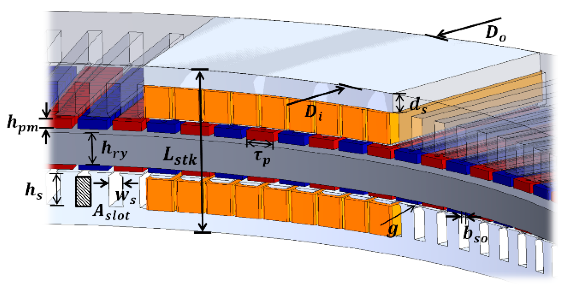
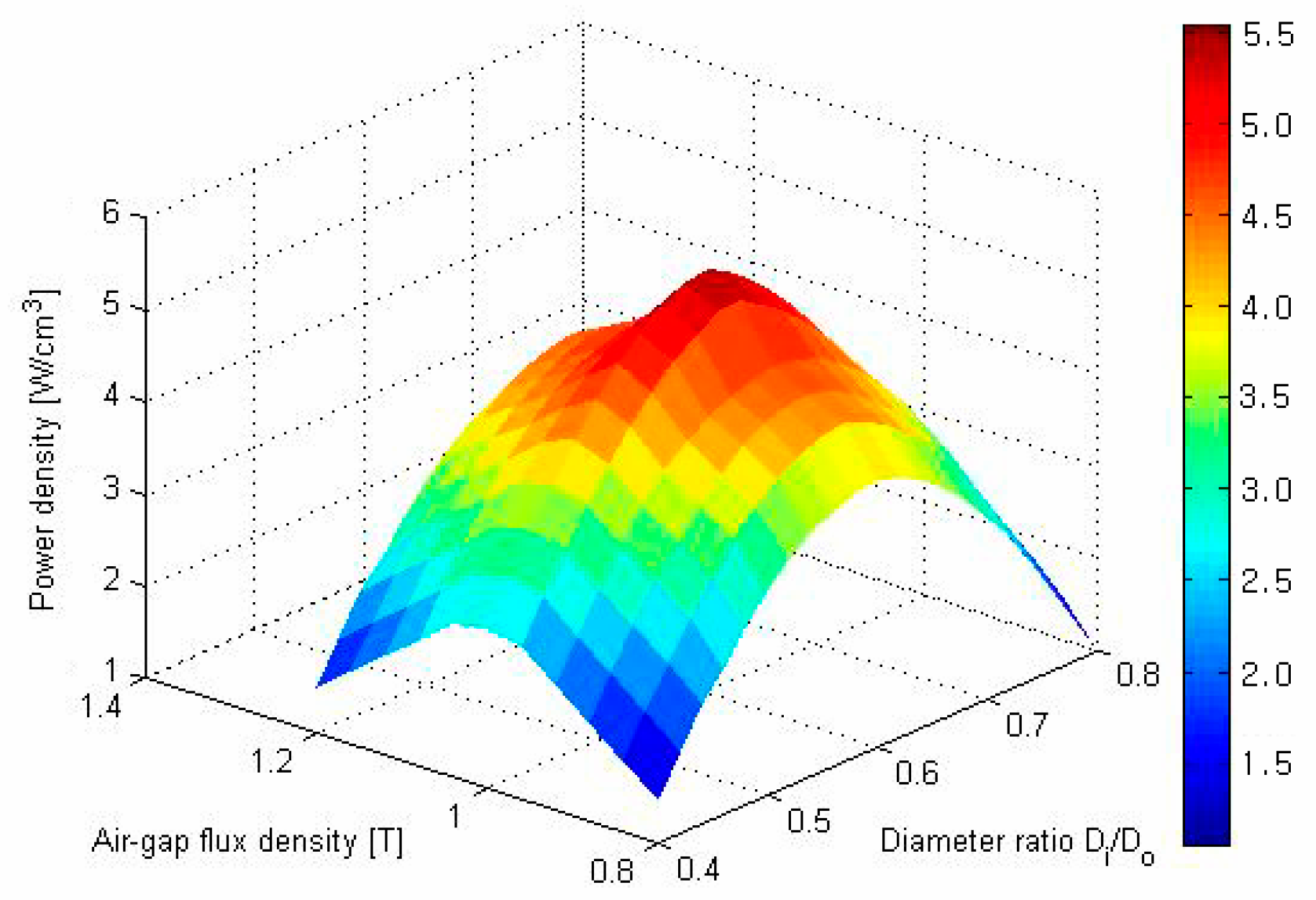
Figure 3.
Power density according to magnetic flux density and diameter ratio.
In the preliminary design stage of an AFPM generator, the major dimensions related to power output can be determined using sizing equations [3]. These equations are derived by applying the mean radius of an AFPM machine to the conventional sizing equations used for radial-flux permanent magnet machines.
Based on the characteristic equations of the AFPM generator, the torque produced per pole of the permanent magnet, , and the torque constant, , can be expressed as follows.
where is the magnet pole-arc ratio, is the stator constant, is the number of series turns, is the winding factor, is the stator current, and is the air-gap flux density. The corresponding back electromotive force (EMF) can be expressed as follows.
By substituting these expressions into the generator output equation, , the resulting form can be written as follows.
where is the coefficient related to the ratio of the outer to inner diameter of the generator. Using this coefficient, the expression can be rewritten as Equation (4).
Due to the inherent characteristics of AFPM machines, maximizing output within a constrained outer diameter requires reducing the inner diameter to increase the effective cross-sectional area. This also leads to a shorter axial length, enabling one of the key advantages of AFPM generators—their compact structure. However, reducing the inner diameter to shorten the axial length while maintaining the same outer diameter can result in output inefficiencies. Therefore, an appropriate ratio between the inner and outer diameters, , must be selected during the AFPM design process.
Since the inner and outer diameters of the stator and rotor are among the most critical factors determining generator performance, the output density was compared as a function of the diameter ratio and air-gap flux density, as shown in Figure 3. Considering the maximum output of the generator, torque calculated based on the output equation yields an optimal diameter ratio of approximately . However, in practical manufacturing, applying a ratio below 0.6 becomes difficult. As the inner diameter decreases, interference between the stator winding end-turns and the shaft must be taken into account. Additionally, in large-capacity machines, the axial forces increase significantly, causing mechanical components to enlarge, which negatively affects both size and cost.
Therefore, when designing the generator, the axial forces generated between the permanent magnets and stator at different diameter ratios must be considered to determine approximate dimensions for the stator yoke, frame, and rotor disk yoke. In this study, various performance characteristics corresponding to the diameter ratio were analyzed and incorporated into the final design.
The load distribution according to was examined for generators of the same power rating, and an appropriate value was selected based on this analysis. Figure 4 illustrates the relationship between the air-gap flux density and the line current density as a function of .
Based on these results, the overall generator volume, weight, and torque density were calculated and are presented in Figure 5. Considering these various characteristics as a function of , along with verification through detailed analysis, the diameter ratio for the AFPM generator proposed in this study was determined to be .
In this study, a quasi–3D analysis model is introduced, in which the AFPM machine is divided into five radial slices to approximate the behavior of a full 3D finite element model. Although a simplified 2D linear model can be derived by using the average values of the inner and outer radii, the analysis results obtained from such a model deviate significantly from those of a full 3D analysis. This discrepancy occurs because the flux density is not uniform due to leakage reactance components near the inner and outer radii of the generator, leading to differences from the actual machine characteristics.
To address this issue, correction factors based on the inner and outer radii are applied in the quasi–3D model, enabling more accurate prediction of machine performance. The validity of the proposed quasi–3D model is verified by comparing its analysis results with those obtained from the full 3D finite element model.
Figure 5 shows the basic concept of the quasi–3D model. In this approach, the 3D model of the machine is divided into multiple segments along the radial direction, from radius to . Each segmented region is then converted into an equivalent 2D model, and the overall characteristics are obtained by superimposing the analysis results of all segments. Figure 6 presents the major variables used in the quasi–3D analysis model.
In this method, the circumferential length at each radial position is aligned with the direction of rotor motion, and the major stator and rotor dimensions are modeled as functions of the radius, . Each radial segment is then converted into a 2D model by accounting for the lamination length, . The number of slices, , used in the quasi–3D approach varies depending on the analysis objective. For example, if the magnet width, stator slot width, and slot pitch remain constant along the radial direction, the generator characteristics can be analyzed using a single slice. In such cases, the key parameters related to machine performance can be obtained using basic magnetic equivalent circuit methods.
Although the structural characteristics of AFPM machines typically require full 3D finite element analysis, the characteristics can still be approximately predicted using a single-slice 2D model based on the mean radius. However, when the slot opening ratio or other radial geometric variations differ among regions, the accuracy of a single-slice model decreases significantly. To address this limitation, a multi-slice approach with slices is employed, allowing each segment to be analyzed independently and combined to obtain an overall, more accurate representation of the machine behavior.
3. Analysis Results
The validity of the proposed quasi–3D model was verified by comparing its analysis results with those obtained from the full 3D finite element model. In addition, to examine the effects near the inner and outer diameter boundaries of the generator, the radial flux density components were evaluated and compared among three cases: the 3D analysis model, the quasi–3D model, and the quasi–3D model incorporating the flux correction factor . The results show that within the effective cross-sectional region, all models yield nearly identical flux density distributions. However, at the inner and outer diameter boundaries, the quasi–3D model including the flux correction factor demonstrates close agreement with the 3D analysis results.
Figure 7.
Analysis results of magnetic flux curve (3D-quasi model and 3D model).
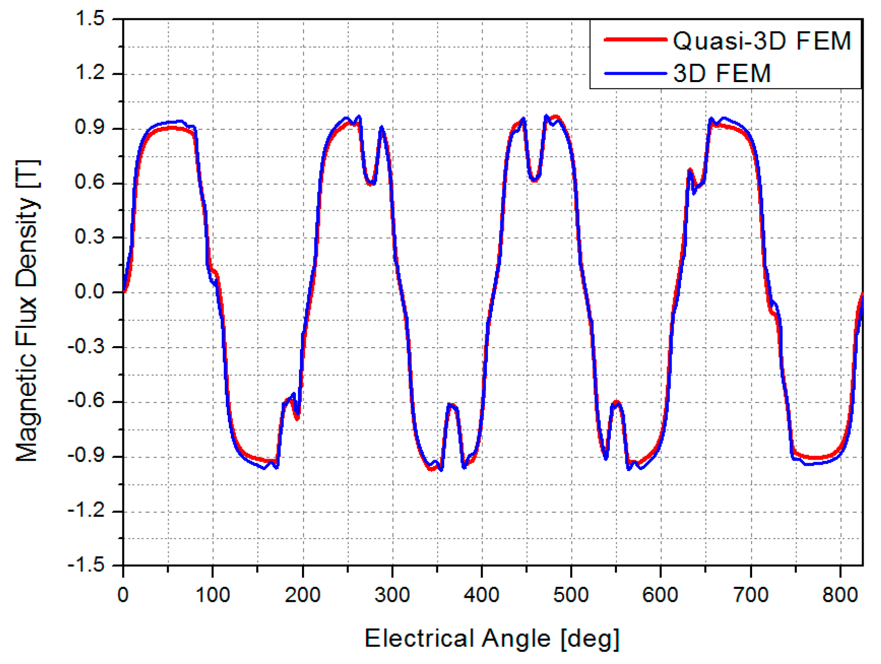
Figure 8 shows the flux density distribution obtained using both the quasi–3D model and the full 3D model. The results correspond to the no-load condition of the generator. Except for the region near the top of the stator tooth, the flux density along the tooth width is approximately 1.2 T in both models, demonstrating close agreement between the two analysis approaches.
Next, the demagnetization characteristics of the permanent magnets were evaluated under a phase-winding short-circuit condition. At the rated rotational speed, one phase of the stator winding was intentionally short-circuited, and the minimum flux density in the magnets was examined to determine whether irreversible demagnetization would occur. The permanent magnets used in the current design are N44SH grade, for which irreversible demagnetization may occur when the flux density falls below 0.1 T at 120 °C. Therefore, a design threshold of 0.3 T was adopted in this study.
Figure 9 and Figure 10 show the analysis results of the short-circuit current and flux density distribution. Under the short-circuit condition, the stator current was calculated to be 8,000 A, while the flux density in the permanent magnets remained at approximately 0.4 T, indicating that demagnetization does not occur under this condition.
4. Test Results
The generator structure employed in this study is an internal-rotor type consisting of two stators on both sides and a rotor positioned at the center. The assembly components can be classified into two stator sets, one rotor set, and the housing and auxiliary brackets. The stators were fabricated using a segmented-core method with dedicated molds, while the rotor was assembled by attaching permanent magnets to the rotor yoke. Once machining and fabrication of the major components were completed, the assembly process was carried out sequentially by placing one stator on the base, followed by the rotor, housing, and the opposite stator. The assembly procedure is relatively simple, and compared to RFPM generators, the process is more straightforward and requires significantly less labor time, offering substantial advantages for manufacturing.
Figure 11 shows a photograph of the fully assembled AFPM generator. The lower support frame was designed and fabricated to withstand the mechanical loads expected during performance testing. The mechanical analysis conducted in this study also included evaluation of the generator’s test support structure. The generator output voltage was measured under no-load conditions while varying the shaft speed from 0 rpm to the maximum speed of 26 rpm. From the design specifications, the calculated output voltage at the rated speed of 16 rpm was approximately 730 V.
Figure 12 presents a comparison between the measured and analyzed rms output voltages as a function of shaft speed. The experimental results show an output of approximately 725 V at 16 rpm, closely matching the analysis, and a linear increase up to 26 rpm. Figure 13 shows the measured output voltage waveform.
To evaluate the effectiveness of the generator cooling system, temperature saturation tests were conducted with and without coolant circulation. Figure 14 shows the results of the temperature saturation test. The ambient temperature was monitored to observe temperature variations, and the experiment was performed in an environment of approximately 20 °C. When the coolant was not circulated, the temperature rise in the stator winding and core reached approximately 100 °C and 50 °C, respectively. In contrast, with coolant circulation, the stator winding temperature increased to only about 74 °C and the core temperature to about 38 °C. These results confirm that the stator winding current density was appropriately designed and that the cooling system provided a temperature reduction of more than 25 °C.
Table 2 presents a comparison between the measured generator test results and the corresponding analysis results.
5. Conclusions
In this study, the design and analysis methodology for a large-capacity AFPM generator was proposed. To verify the validity of the design approach, a 2.5 MW direct-drive axial flux permanent magnet generator was designed, and a prototype was manufactured to confirm the analytical methods. The complete design and analysis procedure for the AFPM generator was presented, along with an analytical model for performance prediction. The proposed methodology was validated through comparative analysis with results obtained from a 3D finite element model, as well as through performance testing of the 2.5 MW prototype. These results confirm the effectiveness and accuracy of the proposed design and analysis framework.
References
- Shrestha, G.; Polinder, H.; Bang, D.J.; Ferreira, J.A.; McDonald, A.S. A New Concept for Weight Reduction of Large Direct Drive Machines. In Proceedings of the 18th International Conference on Electrical Machines, Vilamoura, Portugal, 6–9 September 2008; pp. 1–6. [Google Scholar]
- Leilai, L. Distributed Generation, Induction and Permanent Magnet Generators; Wiley: Hoboken, NJ, USA, 2007; pp. 26–28. [Google Scholar]
- Gieras, F. Axial Flux Permanent Magnet Brushless Machines, 2nd ed.; Springer: New York, NY, USA, 2008. [Google Scholar]
Figure 1.
Assembly components of Large-Scale AFPMG.
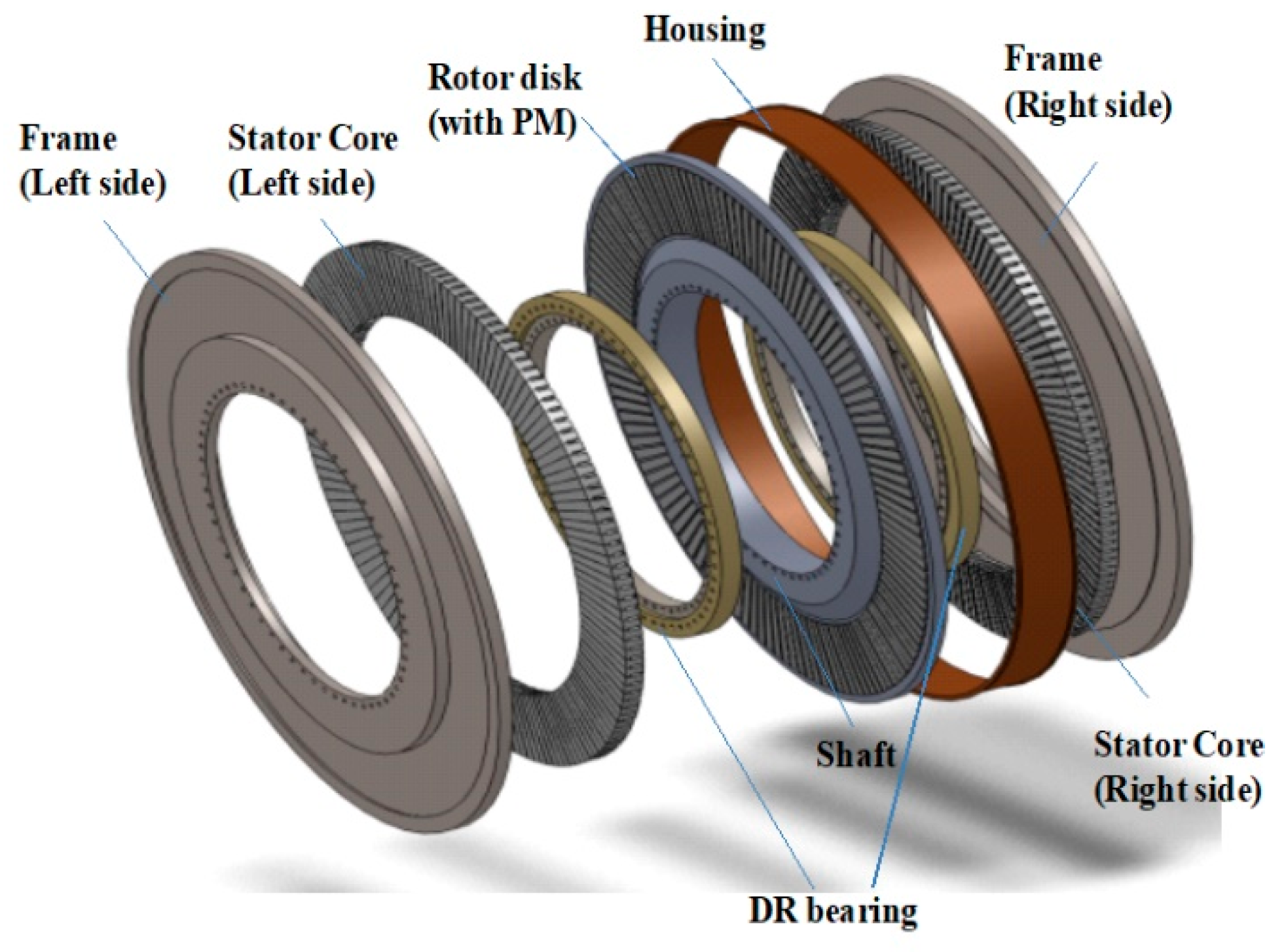
Figure 4.
Magnetic flux density and line current density according to
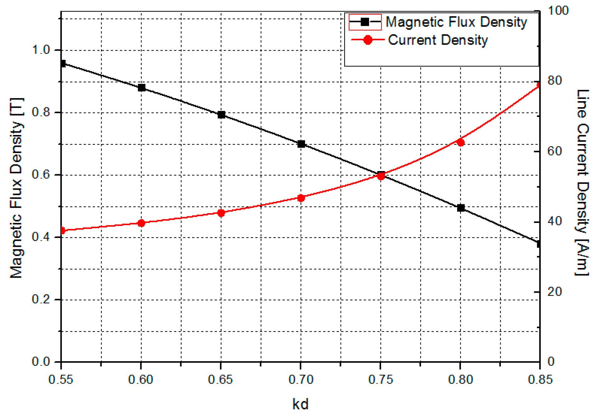
Figure 5.
Volume, weight, material cost and torque density according
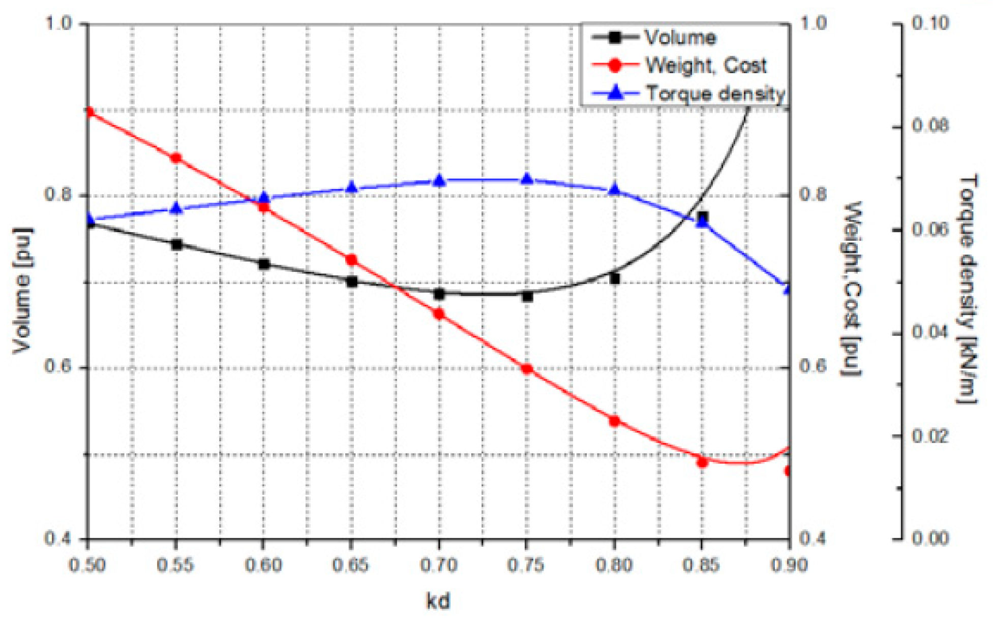
Figure 6.
3D-quasi analysis model of AFPMG.
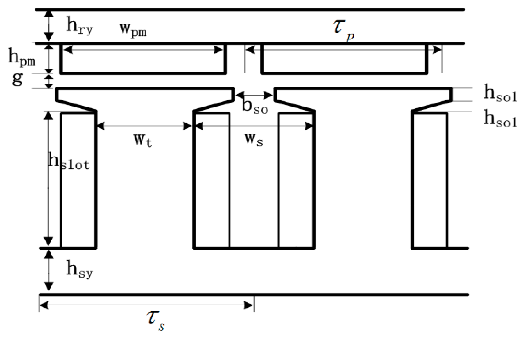
Figure 8.
Analysis results of magnetic flux distribution (3D-quasi model and 3D model).
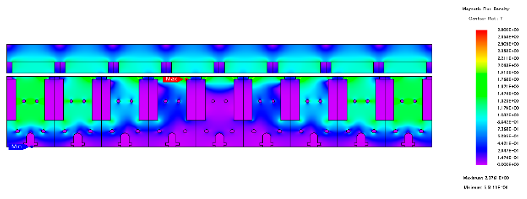
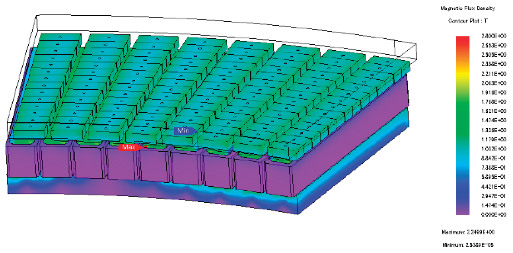
Figure 9.
Analysis results of phase current at 3-phase short condition.
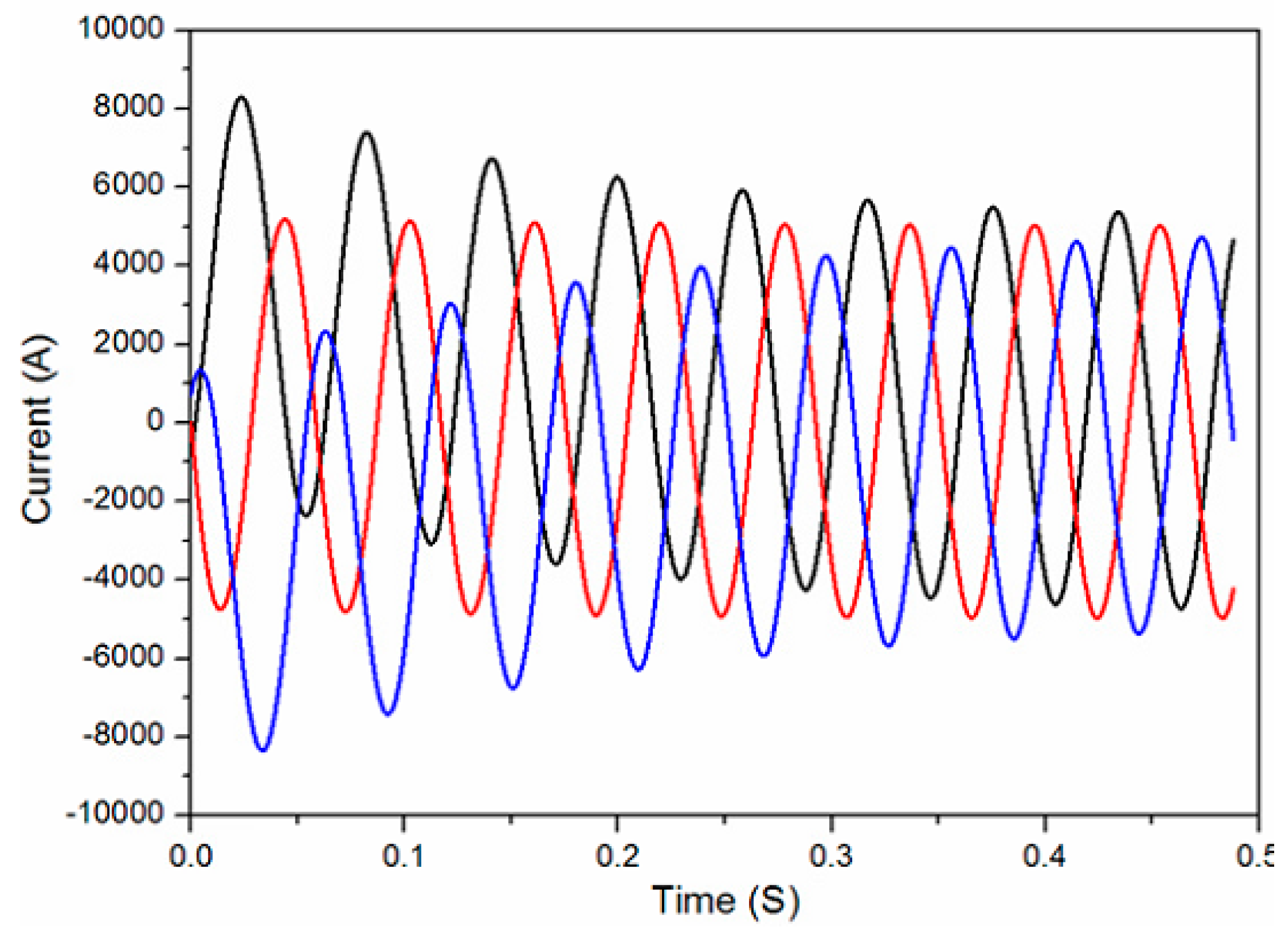
Figure 10.
Analysis results of flux density distribution at 3-phase short condition.
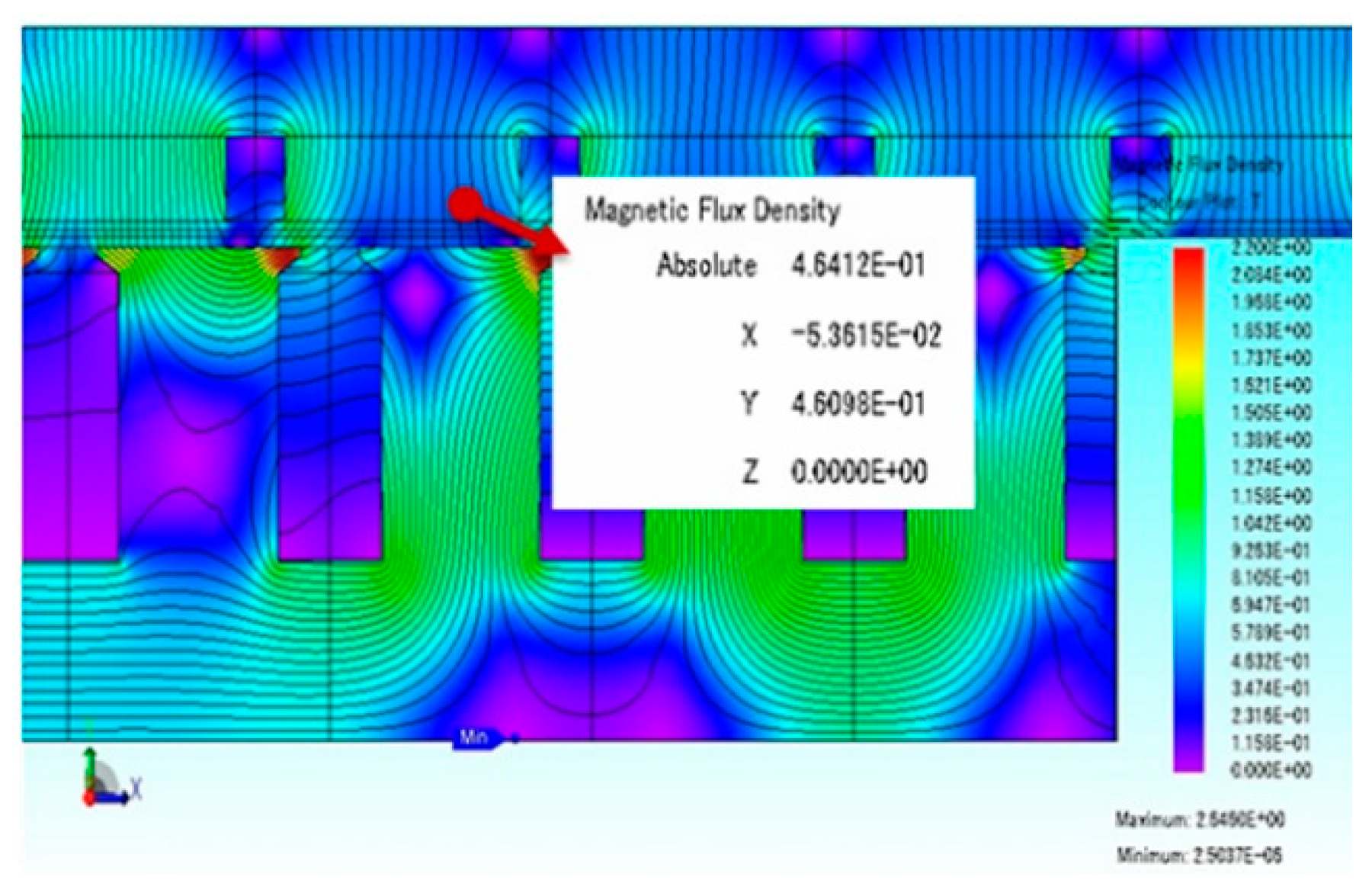
Figure 11.
Prototype of 2.5MW AFPMG and experiment devices.
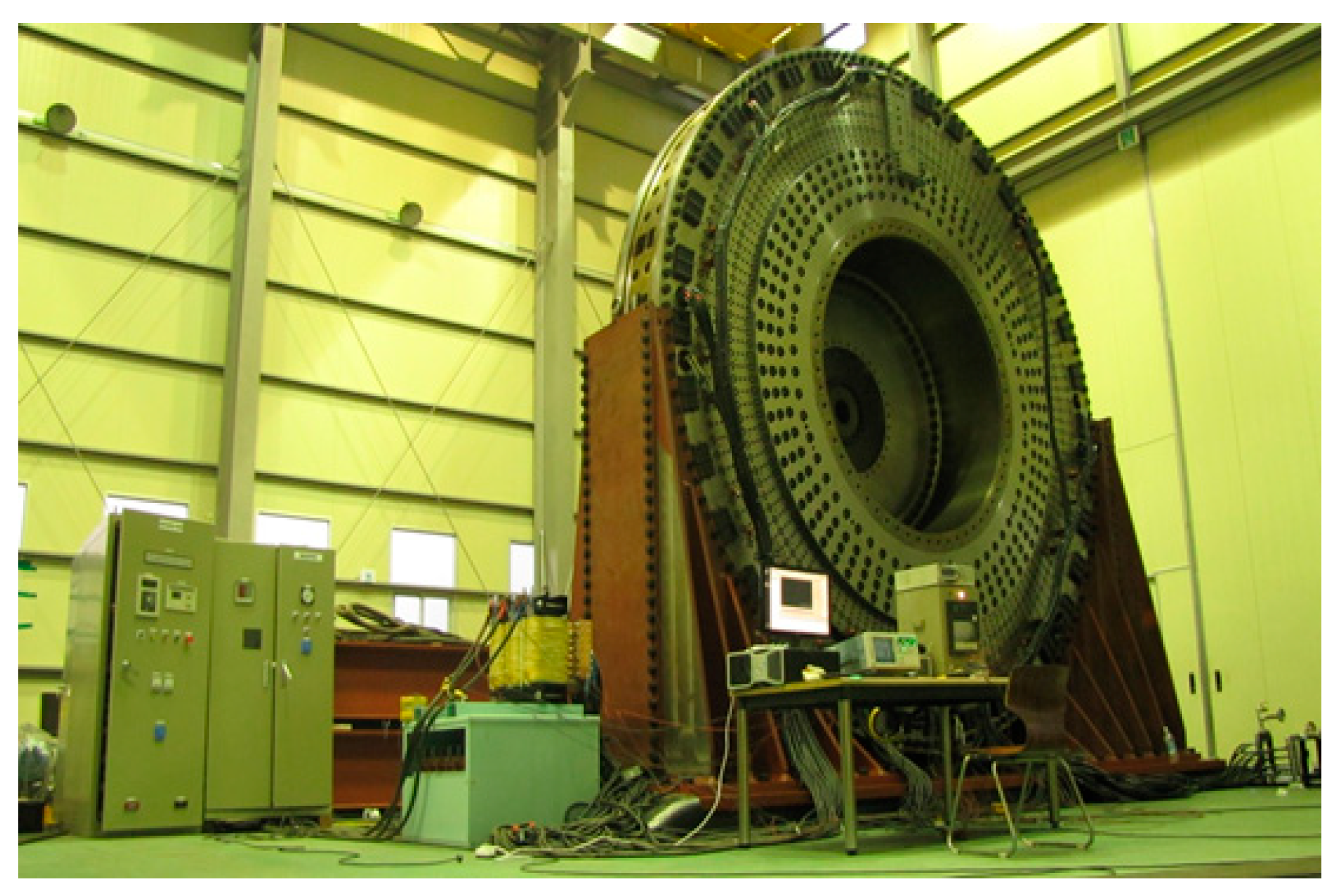
Figure 12.
Test results (Output voltage).
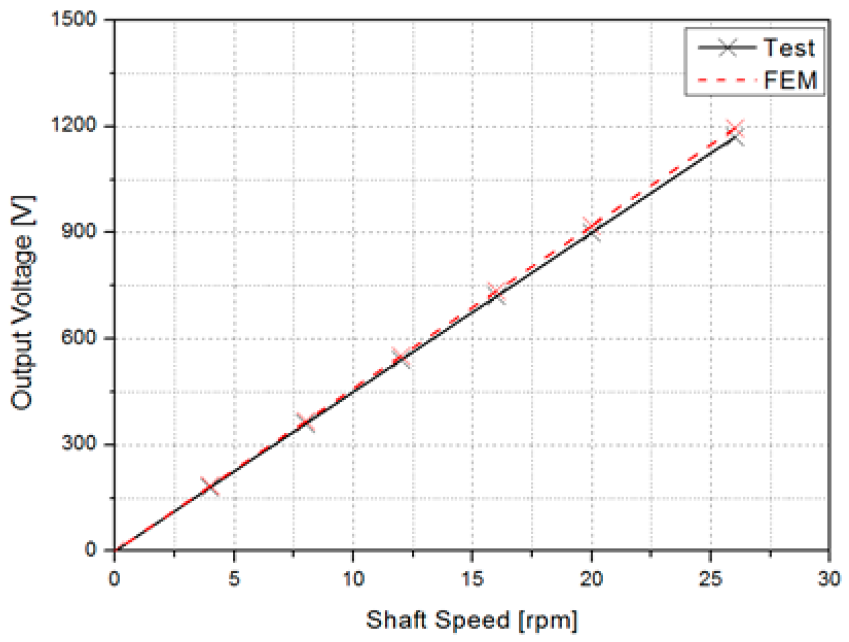
Figure 13.
Test results (Output voltage wave form).
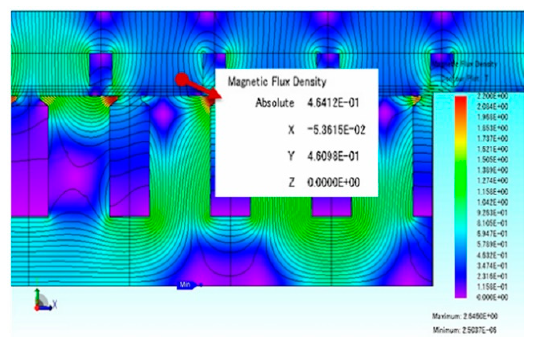
Figure 14.
Test results (Temperature).
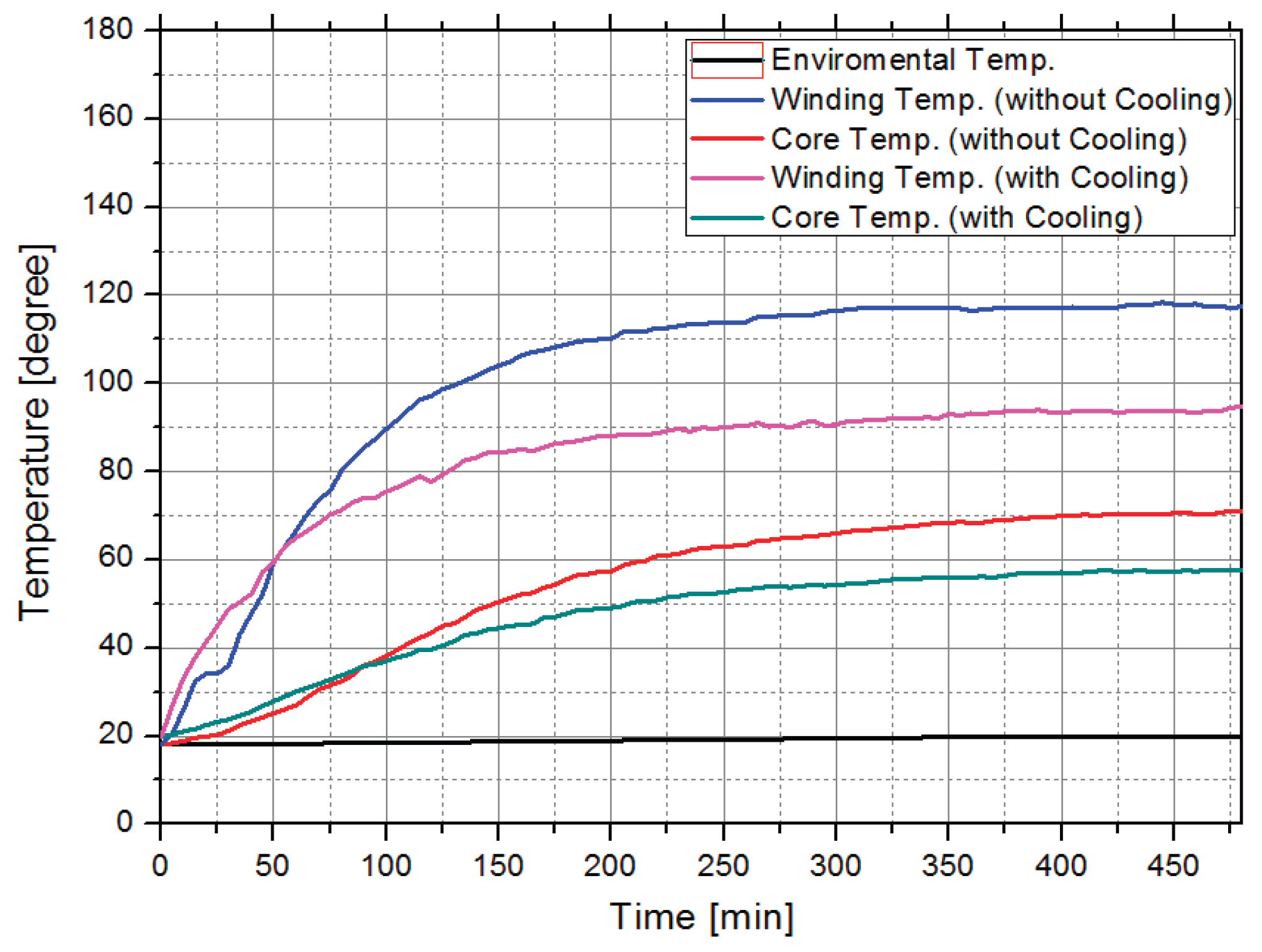

Table 1.
Design specifications of Large-Scale AFPMG.
| Item | Unit | Value |
|---|---|---|
| Current Density | A/mm^2 | Under 3.5 |
| Max. Airgap flux density | T | 0.9 |
| Rated Power | kW | 2,500 |
| Rated Voltage | V | 690 |
| Rated Current | A | 2,270 |
| Rated Speed | Rpm | 16 |
| Rated Torque | kNm | 1,588 |
| Efficiency | % | 94 |
| Power Factor | - | 0.92 |
Table 2.
Test results of AFPMG.
| Item | Unit | Value | |
|---|---|---|---|
| Rated Speed | Rpm | 16 | 16 |
| No Load Voltage | V | 730 | 725 |
| Load Voltage | V | 666.8 | 662.2 |
| THD (No-Load) | % | 10.1 | 12.3 |
| THD (Load) | % | 15.6 | 18.8 |
| Mechanical Loss | kW | - | 40 |
| Core Loss | kW | 46.8 | 50.2 |
| Copper Loss | kW | 74 | 88 |
| Efficiency | % | 93.6 | 92 |
Disclaimer/Publisher’s Note: The statements, opinions and data contained in all publications are solely those of the individual author(s) and contributor(s) and not of MDPI and/or the editor(s). MDPI and/or the editor(s) disclaim responsibility for any injury to people or property resulting from any ideas, methods, instructions or products referred to in the content. |
© 2025 by the authors. Licensee MDPI, Basel, Switzerland. This article is an open access article distributed under the terms and conditions of the Creative Commons Attribution (CC BY) license (https://creativecommons.org/licenses/by/4.0/).
Copyright: This open access article is published under a Creative Commons CC BY 4.0 license, which permit the free download, distribution, and reuse, provided that the author and preprint are cited in any reuse.


