
Submitted:
04 November 2025
Posted:
06 November 2025
You are already at the latest version
Abstract
This study presents the development and experimental validation of a novel wind tur-bine emulator (WTE) based on a Doubly-Fed Induction Generator (DFIG). The pro-posed architecture employs an induction motor (IM) driven by a variable frequency drive (VFD) to emulate wind turbine dynamics, offering a cost-effective and low-maintenance alternative to traditional DC motor-based systems. The control strategy, fully implemented in C language, integrates Tip Speed Ratio (TSR)-based Maximum Power Point Tracking (MPPT) with flux-oriented vector control of the DFIG. Experimental results confirm the emulator’s ability to accurately replicate real wind turbine behavior under varying wind conditions. The test bench demonstrates fast dynamic response, with rotor currents settling in 11–18 ms, and active/reactive powers stabilizing within 25–30 ms. Overshoots remain below 10%, and steady-state errors are limited to ±1 A for currents and ±100 W / ±50 VAR for powers, ensuring pre-cise power regulation. The speed tracking error is approximately 0.61 rad/s, validating the system’s ability to follow dynamic references with high accuracy. Additionally, ef-fective decoupling between active and reactive loops is achieved, with minimal cross-coupling during step changes.
Keywords:
wind turbine emulator
; DFIG
; tip speed ratio
; flux-oriented control
1. Introduction
With the growing interest in microgrids, there has been a significant increase in research efforts focused on integrating wind turbine emulators with solar PV and battery storage systems [1,2]. Experimental investigations of such hybrid configurations are anticipated to offer substantial benefits for microgrid applications [3,4]. The present work centers on the development and implementation of a 3-kW laboratory-scale Wind Turbine Emulator (WTE), designed to contribute to the advancement of a 10-kW stand-alone microgrid aimed at agricultural farm electrification, as part of the MG-FARM project [5].
WTE offers a controlled platform for testing power control methods, MPPT algorithms, pitch angle constraints, and other essential elements of wind energy conversion systems (WECS) [6]. Unlike actual wind turbines, which face variable weather conditions and incur high operational expenses, WTEs allow for accurate wind speed simulation, enabling researchers to effectively evaluate and optimize control strategies for WECS [7]. The system comprises two electrically coupled machines: one functions as a motor to mimic the dynamic wind torque based on wind speed, shaft speed, and turbine characteristics, while the other operates as a generator [8,9].
Recent studies have investigated various generator types for wind turbine emulation, such as Permanent Magnet Synchronous Generators (PMSG) and Doubly Fed Induction Generators (DFIG) [10,11,12]. DFIGs are favored in wind turbine applications because of their cost efficiency and ability to operate over a variable speed range from 0.75 to 1.25 per unit synchronous frequency. This flexibility allows for effective control of active and reactive power while minimizing mechanical stress [13,14]. With the stator connected directly to the grid and the rotor excitation managed by a converter handling only 25–30% of the rated power, DFIGs help lower converter costs significantly [15,16]. Conversely, PMSGs are known for their high efficiency and are commonly employed in wind turbine emulators [17]. They do not require external excitation and omit mechanical components like slip rings and gearboxes, enhancing reliability and offering a high power-to-weight ratio [18]. However, PMSGs involve higher upfront costs, more complex manufacturing processes, and potential demagnetization risks under extreme conditions [19]. Moreover, PMSGs rely on power converters for grid connection [20], which can complicate system control and increase overall expenses, posing notable challenges for some projects.
To enhance wind energy capture and optimize performance, WTEs commonly employ Maximum Power Point Tracking (MPPT) algorithms [21]. These algorithms regulate the emulator’s speed to maintain the optimal tip-speed ratio, thereby maximizing power output under varying wind conditions [22]. MPPT strategies for wind turbines are generally classified into Indirect Power Control (IPC) and Direct Power Control (DPC) methods [23]. IPC techniques include approaches such as the Tip Speed Ratio (TSR) [22], Optimal Torque (OT) [24], and Power Signal Feedback (PSF) [25], while DPC methods feature algorithms like Perturb & Observe (P&O) [26], Incremental Conductance (INC) [27], and Optimum Relation-Based (ORB) [28]. Recent progress has seen the development of hybrid MPPT algorithms that combine aspects of IPC and DPC to overcome the limitations of each, as well as AI-based methods utilizing fuzzy logic and neural networks [29], which provide enhanced adaptability in uncertain environments [21]
Numerous studies have aimed to enhance the performance and integration of WTEs, primarily utilizing two types of prime movers: Direct Current Motors (DCM) and Induction Motors (IM). In [22], a 1.5 kW WTE was developed with a DCM driving a DFIG, with real-time control implemented via a dSPACE DS1104 board. Similarly, [30] introduced a WTE based on a DCM coupled to an induction generator, interfaced with a laboratory grid through a back-to-back converter. A 2.2 kW WTE was reported in [31], employing a separately controlled DCM via dSPACE DS1104 and a PMSG connected to the grid through a back-to-back converter controlled by dSPACE DS1103. Reference [32] describes a 2.5 kW separately excited DCM used to emulate the wind turbine rotor, coupled with a self-excited induction generator; the system was implemented using an Advantech-4704 real-time interface and LabVIEW software. In [33], a WTE composed of two identical 1.5 kW IMs was developed, where one machine acts as a motor controlled by a commercial AC drive, and the other functions as a generator regulated by a three-phase IGBT converter, with control executed on an AT91SAM7X256 DSP. A 5 kW IM controlled via vector control, coupled with a 7.5 kW DFIG WTE, was studied in [34] using a TMS320F28377S DSP for control. Reference [35] employed an IM with rotor field-oriented control to emulate the wind turbine, driving a PMSG connected to the grid through a back-to-back converter, with control algorithms running on TMS320F28335 boards. Authors in [36] proposed a 15 kW IM driven by a commercial AC drive coupled with a 5.5 kW induction generator, controlling the WTE with LabVIEW and the generator via Simulink; the experiments focused on fixed-speed wind turbines under short-circuit fault conditions. The WTE in [37] features an IM driven by a VFD mechanically coupled to a DC generator, whose armature is connected to a variable resistive load; control was implemented in MATLAB/Simulink and executed on a DSP TMS28F335. Reference [38] describes a WTE based on a 1.5 kW IM coupled with a 1.5 kW PMSG connected to a DC load through a rectifier, controlled using a dSPACE 1103 board. Although uncommon, a Permanent Magnet Synchronous Motor has been used as a prime mover emulator in [39].
DC machines have been extensively used in WTEs because of their linear response and independent torque and speed control capabilities [6]. However, this approach has notable disadvantages, including the necessity for multiple control loops, precise tuning of controllers, and additional hardware components such as DC power supplies, rectifiers, and choppers, which all add to system complexity and cost. Additionally, the presence of brushes in DCMs increases maintenance demands. On the other hand, IMs controlled via VFDs present a more economical and low-maintenance option. IMs are widely available, compact, and can deliver high power with relatively simple analog speed and torque control [11]. Despite these benefits, the use of an IM as the prime mover coupled with a DFIG for wind turbine emulation has been relatively underexplored. Existing studies on this configuration often lack detailed system descriptions, validated implementation methods, or experimental confirmation.
This paper fills this gap by introducing a novel WTE design that integrates an IM driven by a VFD with a DFIG acting as the generator. The novelty of this work lies in the practical implementation of the system, where the entire control strategy is developed in C language and verified through extensive experimental testing. Moreover, the proposed emulator incorporates a Tip Speed Ratio (TSR)-based MPPT algorithm to realistically replicate wind energy extraction conditions
The main contributions of this paper are summarized as follows:
- The practical hardware realization of a Wind Turbine Emulator employing an IM-DFIG configuration, providing a cost-effective and low-maintenance alternative to traditional DCM-based systems.
- The development of a comprehensive control framework that integrates TSR-based MPPT and DFIG control, fully implemented in C language and experimentally validated.
- A thorough performance assessment demonstrating the efficiency and reliability of the proposed system across a range of simulated wind scenarios.
This paper is structured as follows: Section 2 outlines the general architecture and hardware components of the proposed WTE. Section 3 covers the dynamic modeling of the DFIG-based system. Section 4 explains the control methods, including TSR-based MPPT and DFIG regulation. Section 5 presents the experimental results along with performance evaluation, and Section 6 concludes the study.
2. Wind Turbine Emulator System Overview
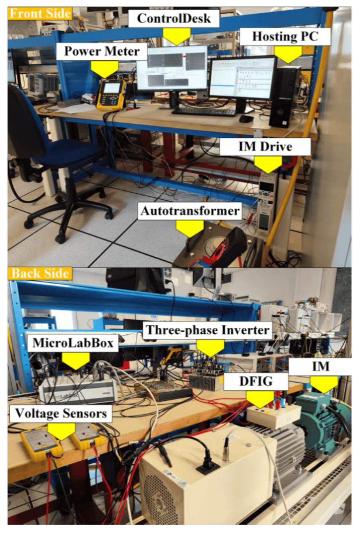
The hardware configuration of the WTE is illustrated in Figure 1. It consists of a 3 kW DFIG MAT30 from Langlois, mechanically coupled to a three-phase induction motor (IM) model LSES 100LG, which is controlled by a Unidrive M700 variable frequency drive (VFD), both supplied by Leroy Somer. The DFIG is connected to the grid through a TRT13A autotransformer rated at 13 kVA, featuring a 380/400V primary winding and a 0–450V secondary winding with a 13A current rating. This transformer serves to adjust voltage levels and enables power injection by matching the generator output voltage to the grid requirements.
The DFIG stator is directly connected to the grid, while its rotor is connected to a three-phase inverter responsible for providing excitation and managing power flow between the DFIG and the grid. This inverter, developed locally, utilizes an FS75R12KT4_B15 IGBT module and EVAL-1ED3491Mx12M gate driver modules from Infineon. Current feedback from the rotor and DC bus is obtained using L18P D15-OP series current sensors, enabling precise regulation of rotor current references to control active and reactive power via rotor flux vector control [22]. Voltage sensors (TA041) from Pico Technology are used to ensure synchronization between the DFIG and the grid.
Instead of using a back-to-back converter, the inverter is powered by a bidirectional DC power supply (SM500-CP-90) from Delta Electronica. This choice simplifies the setup and reduces the number of control signals, allowing greater focus on controlling the machine’s converter side. The bidirectional power supply also plays a crucial role in absorbing active power from the rotor when the DFIG operates in hyper-synchronous mode. Mechanical speed and rotor position are measured using an Incremental Encoder (RIA 40 1024 V L), which employs the index signal for precise shaft angle tracking.
The WTE control is handled by a dSPACE MicroLabBox (MLBX). The MLBX’s ADC inputs receive various measured signals, including two rotor phase currents (Idr, Iqr), inverter DC bus current and voltage (Idc, Vdc), and two grid voltages (Vas, Vbs). The encoder signal is processed through the encoder peripheral interface. Using these inputs, the MLBX generates six PWM signals to regulate the inverter based on voltage references. Additionally, it produces a digital signal that activates a solid-state relay controlling the prime mover’s VFD, allowing switching between open-loop (speed control) and closed-loop (torque control) modes. Speed and torque references are delivered as digital-to-analog outputs from the MLBX, enabling precise control in both modes.
The WTE was initially simulated in MATLAB Simulink, where the control algorithms were implemented in C using an S-function. This approach significantly reduced simulation time and eased the transition to the MLBX platform. Subsequently, the MLBX was programmed in C with the Real-Time Library (RTLib), which provides direct hardware access and complete control over the execution. Detailed instructions on configuring and programming the MLBX with C and RTLib can be found in [40]. The control program starts by initializing the board, followed by creating and activating the necessary I/O driver objects for the MLBX components. At least one Interrupt Service Routine (ISR) is set up to respond to hardware interrupts. The program then runs an infinite background loop to support RTLib’s data exchange services with ControlDesk on the host computer. During each ISR call, control algorithms are executed, and data is updated in ControlDesk for real-time monitoring and interaction with control and graph variables.
C language was chosen because it allows the use of RTLib and C code to significantly increase the sampling rate and PWM frequency of the control algorithms—performance levels that Simulink combined with the Real-Time Interface (RTI) cannot achieve, making it more suitable for demanding applications [40].
3. Modeling of the DFIG-Based Wind Turbine Emulator
3.1. Wind Turbine Model
Aerodynamic models describe the conversion of wind energy into mechanical power, where airflow at a given velocity produces a rotational torque. This torque drives the turbine, which in turn transfers mechanical energy to the generator’s shaft. Wind energy essentially originates from the kinetic energy of vast air masses moving over the earth's surface. When this kinetic energy interacts with the wind turbine’s rotor blades, it is transformed into mechanical energy as expressed by the following equation:
Where and represents the air density (kg/m3), power coefficient, tip speed ratio, blade pitch angle, blade radius (m), wind speed (m/s) and turbine shaft speed (rad/s) respectively.
The mechanical torque applied to the turbine shaft can be calculated using the following expression
By substituting equation (1) into equation (3) and rearranging, the turbine torque can be expressed as:
The power coefficient represents the efficiency with which the turbine converts wind kinetic energy into mechanical energy. It depends on the tip-speed ratio , which defines the relationship between the wind speed and the rotational speed of the turbine blades, as well as the pitch angle of the blades. The expression used to identify for a particular wind turbine [41] is given by:
Figure 2(a) shows how the power coefficient varies with the tip-speed ratio λ for different blade pitch angles. Each curve exhibits a distinct peak, corresponding to the maximum power achievable at the optimal λ for that specific pitch angle. Since λ is dependent on wind speed, the maximum extractable power is strongly influenced by wind velocity. As a result, variable-speed wind turbines are generally more efficient than fixed-speed turbines in capturing the maximum available wind energy.
Figure 2(b) depicts the relationship between the wind turbine (WT) rotor speed and its output power. The maximum power curve indicates the optimal power output achievable under varying wind conditions. The controller’s objective is to keep the turbine operating along this curve by adjusting the rotor speed to align with the ideal operating point for the prevailing wind conditions.
3.2. Dynamic Modeling of the DFIG-Based Wind Turbine Emulator
The differential equations describing the DFIG model are formulated in space vector notation within the stator reference frame, as given in [41]:
Where and are the stator, rotor flux space vectors, the stator, rotor current space vectors, the stator, rotor voltage space vectors, stator and rotor resistances, the stator and rotor inductances, the mutual inductance and the electrical angular frequency of the machine, respectively.
represents the leakage coefficient.
A state-space formulation of the αβ model is particularly useful for computer-based simulations. By choosing the currents as the state variables and substituting equations (8) and (9) into equations (6) and (7), followed by rearrangement, the equivalent DFIG model can be expressed as follows:
Expanding into αβ components, we obtain:
Different state-space models can be formulated depending on the choice of state variables. The full derivation of the model equations is provided in [41].
A simplified mechanical representation is adopted, which can be expressed mathematically as follows:
Where ,, represents the DFIG electromagnetic torque, the external torque acting on the mechanical shaft, equivalent moment of inertia and the rotational speed of the mechanical system, respectively.
The electrical rotational speed and the angle can be easily derived from the mechanical model since the mechanical angular speed, related to the electrical frequency by means of a pair of poles, p as follows:
The state-space model describing the dynamic behavior of the DFIG is implemented in C within Simulink using an S-function block for real-time simulation. This block incorporates the specified inputs, parameters, and outputs. It is important to account for the transformation between the abc and αβ reference frames, as this step is not explicitly shown in Figure 3.
Inputs: Stator and rotor phase voltages in abc form, along with the load torque. The load torque can take positive or negative values, corresponding to motoring or generating operation, respectively.Parameters: Electrical and mechanical characteristics of the machine.Outputs: Stator and rotor phase currents in abc form, electromagnetic torque, rotor speed, and rotor angular position.
4. Control System of the Wind Turbine Emulator
4.1. TSR Based MPPT Wind Turbine Control
To extract maximum power from wind energy, the Tip Speed Ratio (TSR) method is widely adopted in MPPT strategies due to its simplicity and effectiveness. The goal is to maintain the power coefficient at its maximum value , which corresponds to the maximum extractable power . This is achieved by operating the wind turbine at an optimal tip speed ratio for a given pitch angle . The TSR-based MPPT algorithm dynamically adjusts the generator speed to maintain this optimal condition, thereby ensuring maximum power extraction, as illustrated in Figure 4.
For a fixed pitch angle of , the maximum power coefficient, , is obtained at an optimal tip speed ratio of . The corresponding optimal generator speed, is calculated as:
Where are the generator reference speed, gearbox ratio, optimal tip speed ratio, wind speed and turbine radius, respectively.
Since the generator speed is directly proportional to the wind speed, speed regulation is implemented through a feedback control loop, as shown in Figure 4. This loop continuously measures the generator’s rotational speed and compares it to the optimal reference speed derived from the TSR method. A proportional-integral (PI) controller then adjusts the generator torque to align the extracted power with the reference power, thereby optimizing the system’s performance. This approach is straightforward to implement and provides a fast dynamic response. However, it relies on an accurate wind turbine model and precise wind speed measurements for optimal operation.
The TSR-based MPPT algorithm is applied only within one specific operating region, as the operating range of a variable-speed wind turbine is divided into four primary regions, defined by equation (15) and illustrated in Figure 5.
The most critical operating region is Region 2, which lies between the cut-in wind speed and the rated wind speed . In this region, the MPPT algorithm is actively applied to maximize energy production by maintaining the power coefficient at its peak value through rotor speed adjustment in response to wind speed changes. As a result, the tip speed ratio is kept at its optimal value . In Region 3, the control mechanism adjusts the blade pitch angle to regulate the extracted power, keeping it at the turbine's rated power even when wind speeds exceed the rated value. Regions 1 and 4 correspond to the turbine’s parking mode, activated for safety when wind speeds are below the cut-in speed or exceed the cut-out speed . Below the cut-in speed, the wind lacks sufficient energy to efficiently drive the rotor, while speeds above the cut-out risk damaging the turbine due to excessive forces. In parking mode, the blade pitch angle is set to its maximum to minimize wind impact, and the braking system is engaged to safely shut down the turbine.
4.2. DFIG Control
To generate the desired active and reactive power, the MPPT control loop outputs a speed reference for the speed control loop, which in turn determines the active power reference P*. The reactive power reference Q* is typically set manually. This arrangement underscores the necessity for a control strategy that can independently regulate active and reactive power in the DFIGURE Among the various control methods developed for DFIGs, this section focuses on flux-oriented control. Flux-oriented control establishes the relationship between the stator power and the rotor currents injected by the inverter on the rotor side. Specifically, the direct axis component of the rotor current is linked to the stator reactive power, while the quadrature axis component corresponds to the torque or stator active power. This relationship is described through the DFIG model expressed in the synchronous dq reference frame, as shown in the following equations [42,43].
Based on the simplified DFIG model, the rotor voltages are expressed as functions of the rotor currents as follows:
The objective is to regulate the rotor currents by applying the appropriate rotor voltages through PI controllers, achieving decoupled control of the active and reactive power components, as illustrated in the flux-oriented control scheme of the DFIG shown in Figure 6.
5. Experimental Results
The layout of the WTE and its associated control system is presented in Figure 7, with the relevant control parameters listed in Table 1. The control scheme is executed on a dSPACE MicroLabBox (MLBX) using C programming and the RTLib library. As illustrated in Figure 8, the MLBX receives measurements of the DFIG rotor phase currents, stator phase voltages, rotational speed, and rotor position via its analog input channels and encoder interface. These signals are processed within the controller to run the control algorithm, which generates the required outputs, namely the PWM gating signals and the torque reference. The PWM signals are then delivered to the inverter driver to control the switching of the GBT bridge. The entire operation can be monitored in real time through the ControlDesk environment.
The performance and adaptability of the proposed WTE were assessed through both simulation and laboratory experiments; however, only the experimental findings are reported here, as they showed strong agreement with the simulated results. One operating condition was examined. The turbine was driven by a sinusoidal wind speed profile. This test allowing performance evaluation of the complete WECS under TSR-based MPPT operation.
A sinusoidal wind speed profile with a period of 76 seconds and an average speed of 7 m/s is used for the test.
When the switch in Figure 7 is set to position 1, the wind turbine emulator’s controller produces a torque reference for the drive according to the given wind profile and turbine characteristics. In this configuration, the drive functions in closed-loop torque control mode. At the same time, the TSR-based MPPT strategy determines the speed reference for the DFIG controller, enabling the system to generate the optimal active power for grid injection.
The wind profile depicted in Figure 8(a) fluctuates randomly between 5.5 m/s and 8.5 m/s, crossing 7 m/s—the wind speed that corresponds to the DFIG’s synchronous speed of 1500 rpm. For wind speeds below 7 m/s, the generator operates in sub-synchronous mode, with the stator delivering power and the rotor consuming it. When the wind speed exceeds 7 m/s, the system enters hypersynchronous mode, in which both stator and rotor contribute to power generation. This profile provides realistic operating conditions for evaluating the performance of the wind turbine emulator.
The torque produced at the turbine shaft varies proportionally with the wind speed, as expressed in Equation (4). This torque is adjusted by the gearbox ratio to obtain the corresponding motor torque, enabling the motor to follow the wind speed profile closely. For simplicity, torque fluctuations arising from wind gradient and tower shadow effects are disregarded, and the gearbox is considered ideal. This approach allows for a precise replication of wind turbine dynamics under realistic operating conditions.
Figure 8(b) shows the strong correlation between the reference and measured DFIG rotor speeds. The TSR-based MPPT controller generates the speed reference, which is accurately tracked by the PI speed control loop. The rotor speed profile exhibits a sinusoidal variation that directly follows the wind speed pattern shown in Figure 8(a), ensuring realistic emulation of wind turbine operation. Throughout the test, the rotor speed smoothly follows the reference within the range of approximately 115 rad/s to 180 rad/s, with minimal steady-state error. This precise tracking keeps the tip-speed ratio close to its optimal value, maximizing aerodynamic efficiency and maintaining a high-power coefficient for effective energy conversion.
Figure8(c) presents the grid voltage components Vd and Vq , demonstrating the successful synchronization of the DFIG with the grid through a Phase-Locked Loop (PLL). The PLL maintains precise alignment between the rotor reference frame and the grid voltage, ensuring stable and reliable operation. Minor fluctuations are visible in the voltage signals, mainly due to measurement noise inherent to the experimental setup. Nevertheless, the synchronization remains accurate, enabling consistent power exchange with the grid.
Figure 8(d) shows the quadrature rotor current Iqr and its optimal reference Iqr_ref, derived from the active power reference through the speed reference generated by the TSR-based MPPT algorithm. The profile of Iqr follows the sinusoidal speed variation imposed by the wind profile, with high tracking accuracy ensured by the precise tuning of the PI controller.
Figure 8(e) illustrates the direct rotor current Idr before and after reactive power compensation. At t=28 s, Idr increases sharply from approximately 0 A to 14 A to supply 1500 VAr. This response demonstrates the reactive power controller’s ability to adjust Idr as required, achieving excellent tracking performance and confirming the effectiveness of the PI regulator in following the reference trajectory.
Figure 8(f) presents the rotor phase currents during the transition through the synchronous speed of the DFIGURE The plot clearly shows the change in the rotor current phase sequence as the system moves from sub-synchronous to hyper-synchronous operation, corresponding to a slip change from positive to negative. The zoomed view highlights the waveform details around the transition, evidencing the smooth but distinct phase reversal.
Figure 8(g) depicts the stator power being injected into the grid, with its regulation managed by the TSR-based MPPT algorithm. The results clearly show that the algorithm is able to accurately track the desired power reference, ensuring efficient energy conversion from the wind turbine emulator to the grid under varying wind conditions.
Figure 8(h) presents the reactive power of the DFIG before and after compensation. Prior to compensation, the DFIG absorbs approximately 1500 VAr to provide the necessary magnetization for the machine. After compensation, at t = 28 s, the reactive power exchange between the grid and the DFIG is effectively reduced to zero. The reactive power reaches its desired value rapidly and in a well-damped manner, without causing any disturbance to the active power. This behavior clearly demonstrates the capability of the control algorithm to decouple active and reactive power, ensuring stable and efficient operation of the DFIG while maintaining grid power quality.
The TSR-based MPPT algorithm demonstrates its ability to maximize power extraction across a wide range of transitional rotor speeds. Negative power values indicate that energy is being delivered to the grid. The high performance of the PI current controllers ensures precise tracking of both active and reactive power. Additionally, the DFIG draws approximately 1500 VAr of reactive power to establish the necessary magnetic flux.
Figure 8(i) illustrates the DC bus current, which reflects the rotor power exchange of the DFIGURE When the machine operates in sub-synchronous mode, the DC bus current is negative, indicating that the rotor is absorbing power from the grid. Conversely, during super-synchronous operation, the DC bus current becomes positive, showing that the rotor is injecting power into the grid. It is important to note that the DC source used in this setup is reversible, allowing bidirectional power flow; in a conventional DC bus configuration, additional protection would be required to safely handle power reversal.
Figure 9.
WTE Experimental setup.
6. Conclusions
This work successfully implemented a wind turbine emulator using a DFIG, regulated through the TSR algorithm combined with flux-oriented control strategies. Constructed with an induction motor and a commercial frequency inverter, the emulator demonstrated strong reliability in mimicking the dynamic behavior of actual wind turbines. It offered a versatile and dependable platform for investigating wind energy conversion systems under a range of operating scenarios, including conditions with unbalanced wind speeds.
The implementation of the TSR-based MPPT algorithm allowed for optimal extraction of wind energy, while flux-oriented control ensured accurate regulation of the DFIG rotor currents, supporting efficient and stable operation. Experimental results confirmed the emulator’s effectiveness, showing its ability to replicate real wind turbine behavior and providing a valuable platform for testing and validating control strategies in wind energy systems.
Despite these advantages, several limitations were observed in the developed setup. The direct rotor current exhibited overshoot during active-power tests, which could impose stress on the rotor-side converter. Minor transient ripples and oscillations in current and power were also detected, potentially affecting power quality and causing slight mechanical torque fluctuations. The settling time for both active and reactive power responses may be borderline for meeting strict fast-disturbance rejection requirements in some grid codes. Additionally, small residual coupling effects persisted, indicating that full decoupling between active and reactive control loops was not completely achieved. The reactive power control loop, in particular, showed a higher tendency for overshoot during reactive-power tests.
Acknowledgments
The MG-FARM project has received funding from the European Union’s Horizon 2020 Research and Program under Grant Agreement 963530.
Conflicts of Interest
The authors declare no conflicts of interest.
References
- Bennia, Y. Daili, A. Harrag, H. Alrajhi, A. Saim, and J. M. Guerrero, « Stability and Reactive Power Sharing Enhancement in Islanded Microgrid viaSmall-Signal Modeling and Optimal Virtual Impedance Control », Int. Trans. Electr. Energy Syst., vol. 2024, no. 1, p. 5469868, 2024. [CrossRef]
- W. Issa, S. Sharkh, et M. Abusara, « A review of recent control techniques of drooped inverter-based AC microgrids », Energy Sci. Eng., vol. 12, no 4, p. 1792-1814, avr. 2024. [CrossRef]
- M. K. Senapati, O. M. K. Senapati, O. Al Zaabi, K. Al Hosani, K. Al Jaafari, C. Pradhan, et U. R. Muduli, « Advancing electric vehicle charging ecosystems with intelligent control of DC microgrid stability », IEEE Trans. Ind. Appl., 2024.
- Bennia, Y. Daili, A. Harrag, H. Alrajhi, A. Saim, et J. M. Guerrero, « Stability and Reactive Power Sharing Enhancement in Islanded Microgrid via Small-Signal Modeling and Optimal Virtual Impedance Control », Int. Trans. Electr. Energy Syst., vol. 2024, no 1, p. 5469868, 2024.
- Bennia, *!!! REPLACE !!!*; et al. , « Design, modeling, and validation of grid-forming inverters for frequency synchronization and restoration », Energies, vol. 17, no 1, p. 59, 2023.
- Z. Maheshwari, K. Kengne, et O. Bhat, « A comprehensive review on wind turbine emulators », Renew. Sustain. Energy Rev., vol. 180, p. 113297, juill. 2023. [CrossRef]
- D. Zouheyr, B. D. Zouheyr, B. Lotfi, et B. Abdelmadjid, « Real-Time Emulation of a Grid-Connected Wind Energy Conversion System Based Double Fed Induction Generator Configuration under Random Operating Modes. », Eur. J. Electr. Eng. Int. Génie Electrique, vol. 23, no 3, 2021, Consulté le: 6 novembre 2024.
- M. M. Rezaei, « A nonlinear maximum power point tracking technique for DFIG-based wind energy conversion systems », Eng. Sci. Technol. Int. J., vol. 21, no 5, p. 901-908, oct. 2018. [CrossRef]
- K. Ouari et Y. Belkhier, « Model predictive direct torque algorithm for coordinated electrical grid operation of wind energy conversion system-based doubly fed induction generator », Int. J. Model. Simul., p. 1-14, 2024.
- M. K. Senapati, C. M. K. Senapati, C. Pradhan, P. K. Nayak, S. Padmanaban, et T. Gjengedal, « Modified demagnetisation control strategy for low-voltage ride-through enhancement in DFIG-based wind systems », IET Renew. Power Gener., vol. 14, no 17, p. 3487-3499, 2020.
- S. Rajendran, M. S. Rajendran, M. Diaz, V. Devi, D. Jena, J. Travieso, et J. Rodriguez, « Wind Turbine Emulators—A Review », Processes, vol. 11, no 3, p. 2023. [Google Scholar] [CrossRef]
- Bennia, Y. Daili, and A. Harrag, «Hierarchical control of paralleled voltage source inverters in islanded single phase microgrids», presented at the Artificial Intelligence and Renewables Towards an Energy Transition 4, Springer, 2021, pp. 302–313. [CrossRef]
- J. C. Martínez, J. L. Rodríguez Amenedo, S. Arnaltes Gómez, et J. Alonso-Martínez, « Grid-forming control of doubly-fed induction generators based on the rotor flux orientation », Renew. Energy, vol. 207, p. 162-176, mai 2023. [CrossRef]
- Z. Dekali, L. Z. Dekali, L. Baghli, T. Lubin, et A. Boumediene, « Grid side inverter control for a grid connected synchronous generator based wind turbine experimental emulator », Eur. J. Electr. Eng., vol. 23, no 1, p. 1-7, 2021.
- M. K. Senapati, C. M. K. Senapati, C. Pradhan, P. K. Nayak, et S. R. Samantaray, « Lagrange interpolating polynomial–based deloading control scheme for variable speed wind turbines », Int. Trans. Electr. Energy Syst., vol. 29, no 5, p. e2824, 2019.
- J. L. Rodriguez-Amenedo, S. A. Gomez, J. C. Martinez, et J. Alonso-Martinez, « Black-Start Capability of DFIG Wind Turbines Through a Grid-Forming Control Based on the Rotor Flux Orientation », IEEE Access, vol. 9, p. 142910-142924, 2021. [CrossRef]
- D. H. Wollz, S. A. O. Da Silva, et L. P. Sampaio, « Real-time monitoring of an electronic wind turbine emulator based on the dynamic PMSG model using a graphical interface », Renew. Energy, vol. 155, p. 296-308, août 2020. [CrossRef]
- S. Huang et al., « A fixed-time fractional-order sliding mode control strategy for power quality enhancement of PMSG wind turbine », Int. J. Electr. Power Energy Syst., vol. 134, p. 107354, janv. 2022. [CrossRef]
- P. Li, L. Xiong, M. Ma, S. Huang, Z. Zhu, et Z. Wang, « Energy-shaping L2-gain controller for PMSG wind turbine to mitigate subsynchronous interaction », Int. J. Electr. Power Energy Syst., vol. 135, p. 107571, févr. 2022. [CrossRef]
- Khan, D. A. Aragon, M. Seyedmahmoudian, S. Mekhilef, et A. Stojcevski, « Inertia emulation control of PMSG-based wind turbines for enhanced grid stability in low inertia power systems », Int. J. Electr. Power Energy Syst., vol. 156, p. 109740, févr. 2024. [CrossRef]
- H. H. H. Mousa, A.-R. Youssef, et E. E. M. Mohamed, « State of the art perturb and observe MPPT algorithms based wind energy conversion systems: A technology review », Int. J. Electr. Power Energy Syst., vol. 126, p. 106598, mars 2021. [CrossRef]
- D. Zouheyr, B. Lotfi, et B. Abdelmadjid, « Improved hardware implementation of a TSR based MPPT algorithm for a low cost connected wind turbine emulator under unbalanced wind speeds », Energy, vol. 232, p. 121039, oct. 2021. [CrossRef]
- D. Kumar et K. Chatterjee, « A review of conventional and advanced MPPT algorithms for wind energy systems », Renew. Sustain. Energy Rev., vol. 55, p. 957-970, mars 2016. [CrossRef]
- Ghaffari, M. Krstić, et S. Seshagiri, « Power optimization and control in wind energy conversion systems using extremum seeking », IEEE Trans. Control Syst. Technol., vol. 22, no 5, p. 1684-1695, 2014.
- F. E. V. Taveiros, L. S. F. E. V. Taveiros, L. S. Barros, et F. B. Costa, « Back-to-back converter state-feedback control of DFIG (doubly-fed induction generator)-based wind turbines », Energy, vol. 89, p. 896-906, 2015.
- B. Lahfaoui, S. B. Lahfaoui, S. Zouggar, B. Mohammed, et M. L. Elhafyani, « Real time study of P&O MPPT control for small wind PMSG turbine systems using Arduino microcontroller », Energy Procedia, vol. 111, p. 1000-1009, 2017.
- Q. Mei, M. Q. Mei, M. Shan, L. Liu, et J. M. Guerrero, « A novel improved variable step-size incremental-resistance MPPT method for PV systems », IEEE Trans. Ind. Electron., vol. 58, no 6, p. 2427-2434, 2010.
- M. A. Abdullah, A. H. M. M. A. Abdullah, A. H. M. Yatim, C. W. Tan, et R. Saidur, « A review of maximum power point tracking algorithms for wind energy systems », Renew. Sustain. Energy Rev., vol. 16, no 5, p. 3220-3227, 2012.
- Bennia, A. Harrag, Y. Daili, A. Bouzid, and J. M. Guerrero, «Decentralized secondary control for frequency regulation based on fuzzy logic control in islanded microgrid», Indones. J. Electr. Eng. Comput. Sci., vol. 29, no. 1, pp. 85–100, 2023. [CrossRef]
- F. Martinez, L. C. F. Martinez, L. C. Herrero, et S. de Pablo, « Open loop wind turbine emulator », Renew. Energy, vol. 63, p. 212-221, 2014.
- M. El Mokadem, V. M. El Mokadem, V. Courtecuisse, C. Saudemont, B. Robyns, et J. Deuse, « Experimental study of variable speed wind generator contribution to primary frequency control », Renew. Energy, vol. 34, no 3, p. 833-844, 2009.
- H. Garg et R. Dahiya, « Modelling and Development of Wind Turbine Emulator for the Condition Monitoring of Wind Turbine », Int. J. Renew. Energy Res., vol. 5, no 2, p. 591-597, 2015.
- J. Castelló, J. M. J. Castelló, J. M. Espí, et R. García-Gil, « Development details and performance assessment of a wind turbine emulator », Renew. Energy, vol. 86, p. 848-857, 2016.
- R. Nair et G. Narayanan, « Emulation of wind turbine system using vector controlled induction motor drive », IEEE Trans. Ind. Appl., vol. 56, no 4, p. 4124-4133, 2020.
- M. Karabacak, L. M. M. Karabacak, L. M. Fernandez-Ramirez, T. Kamal, et S. Kamal, « A new hill climbing maximum power tracking control for wind turbines with inertial effect compensation », IEEE Trans. Ind. Electron., vol. 66, no 11, p. 8545-8556, 2019.
- E. Mohammadi, R. E. Mohammadi, R. Fadaeinedjad, et G. Moschopoulos, « An electromechanical emulation-based study on the behaviour of wind energy conversion systems during short circuit faults », Energy Convers. Manag., vol. 205, p. 112401, 2020.
- J. R. De Oliveira, W. G. De Souza, M. A. Rocha, C. F. da Costa, J. V. F. Leão, et A. L. Andreoli, « Wind turbine emulator using induction motor driven by frequency inverter and hardware-in-the-loop control », in 2018 13th IEEE International Conference on Industry Applications (INDUSCON), Ieee, 2018, p. 381-385. Consulté le: 6 novembre 2024.
- C. Vlad, A. I. C. Vlad, A. I. Bratcu, I. Munteanu, et S. Epure, « Real-time replication of a stand-alone wind energy conversion system: Error analysis », Int. J. Electr. Power Energy Syst., vol. 55, p. 562-571, 2014.
- P.-Y. Chen, K.-W. P.-Y. Chen, K.-W. Hu, Y.-G. Lin, et C.-M. Liaw, « Development of a prime mover emulator using a permanent-magnet synchronous motor drive », IEEE Trans. Power Electron., vol. 33, no 7, p. 6114-6125, 2017.
- L. Baghli et E. Jamshidpour, « Implementing a 200 kHz PWM Field Oriented Control using RTLib and C program on a dSPACE MicroLabBox », in 2022 2nd International Conference on Advanced Electrical Engineering (ICAEE), oct. 2022, p. 1-6. [CrossRef]
- G. Abad, J. López, M. Rodríguez, L. Marroyo, et G. Iwanski, « Dynamic modeling of the doubly fed induction machine », 2011, Consulté le: 15 novembre 2024. [En ligne].
- Z. Dekali, « Contribution à la commande d’un simulateur HIL d’éolienne et d’une génératrice asynchrone à double alimentation », PhD Thesis, 2021. Consulté le: 19 novembre 2024. [En ligne].
- Yasmine, E. B. Chakib, et B. Badre, « Power control of DFIG-generators for wind turbines variable-speed », Int. J. Power Electron. Drive Syst. IJPEDS, vol. 8, no 1, p. 444-453, 2017.
Figure 1.
Overall scheme of the experimental hardware configuration of the emulated WT.
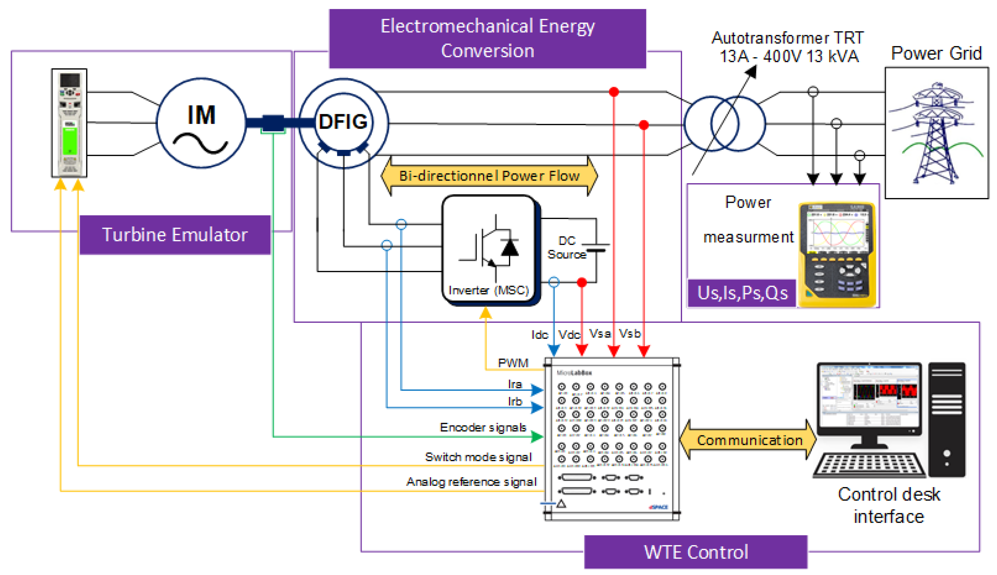
Figure 2.
WTE characteristics (a) Cp for different blade pitch angle; (b Output power for different wind speed.
Figure 2.
WTE characteristics (a) Cp for different blade pitch angle; (b Output power for different wind speed.
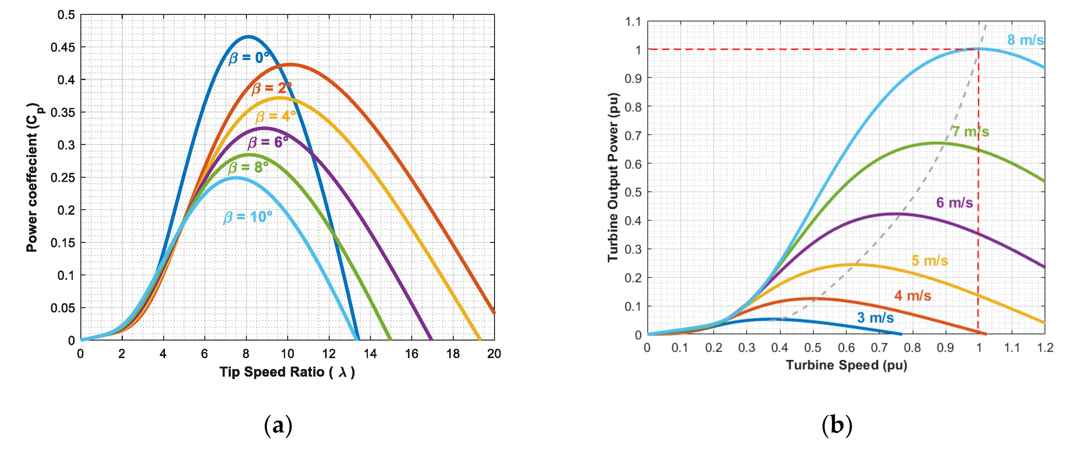
Figure 3.
Input–output structure of the DFIG dynamic model.
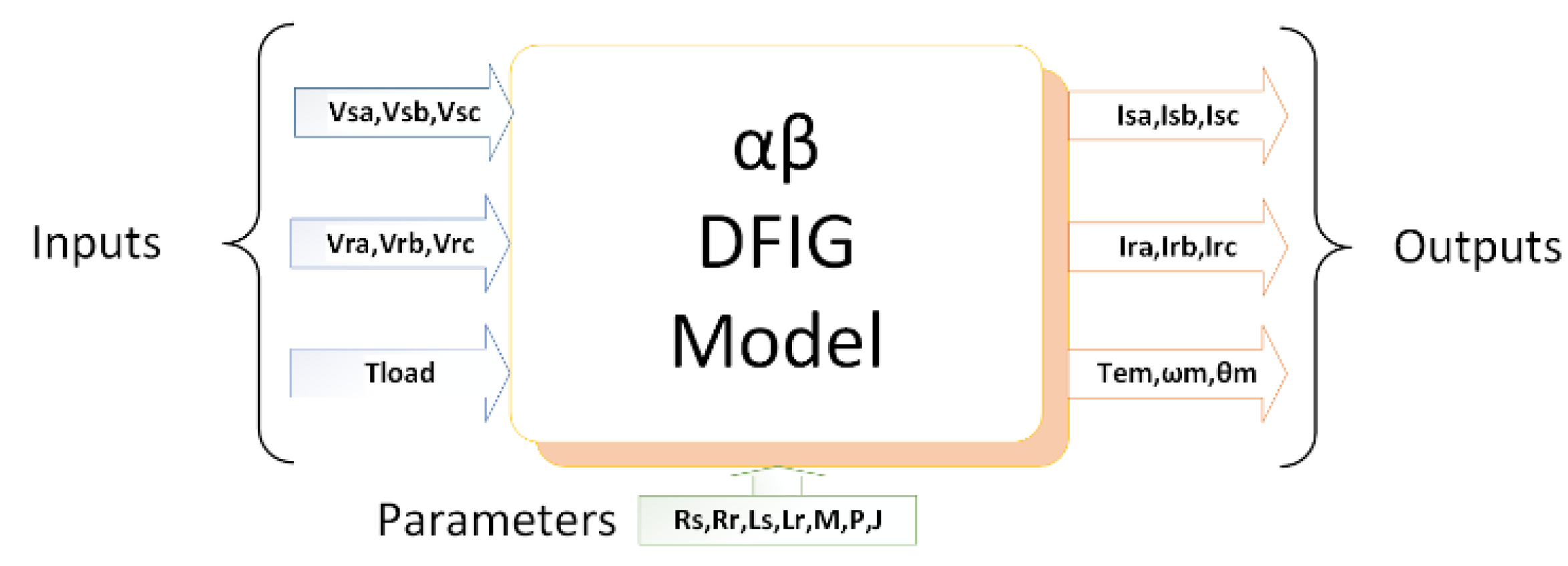
Figure 4.
MPPT based TSR control algorithm.
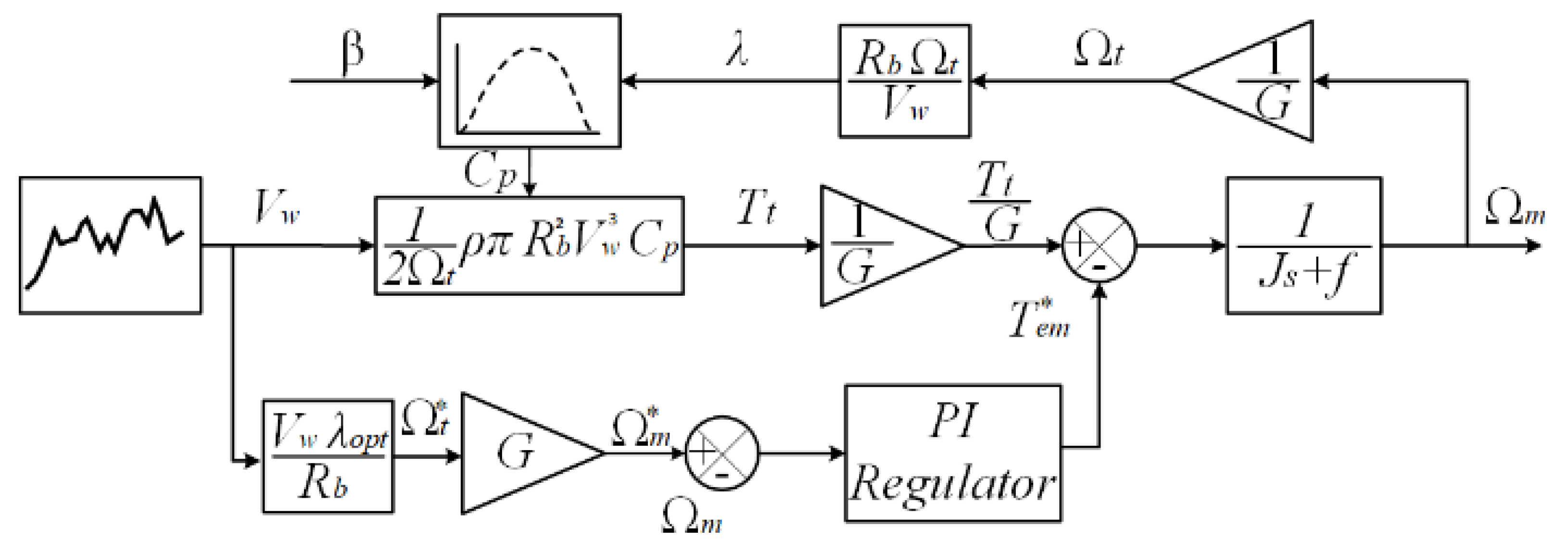
Figure 5.
Operating regions of variable speed wind turbines.
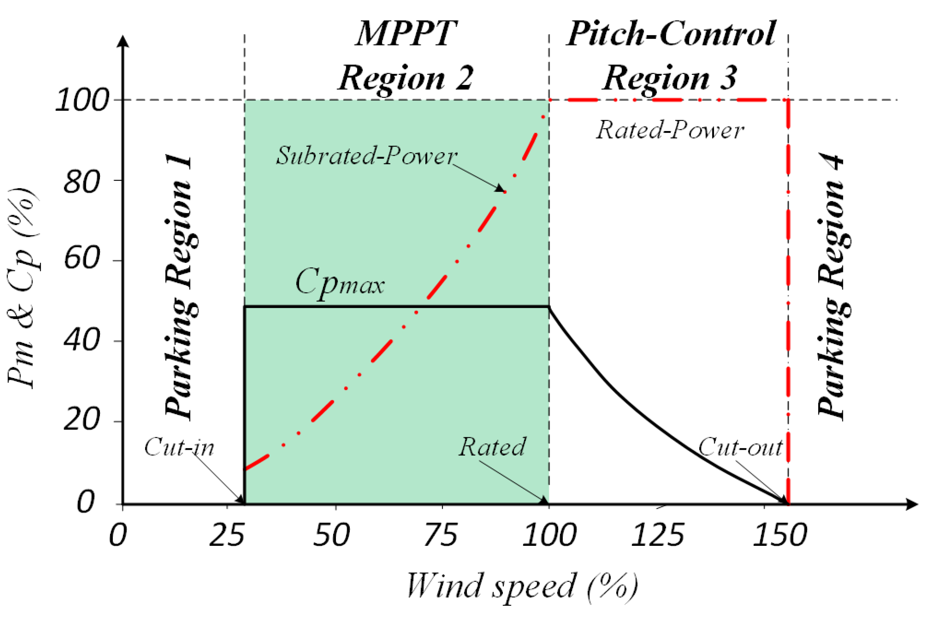
Figure 6.
Flux-Oriented Control of the DFIG Utilizing PI Controllers.
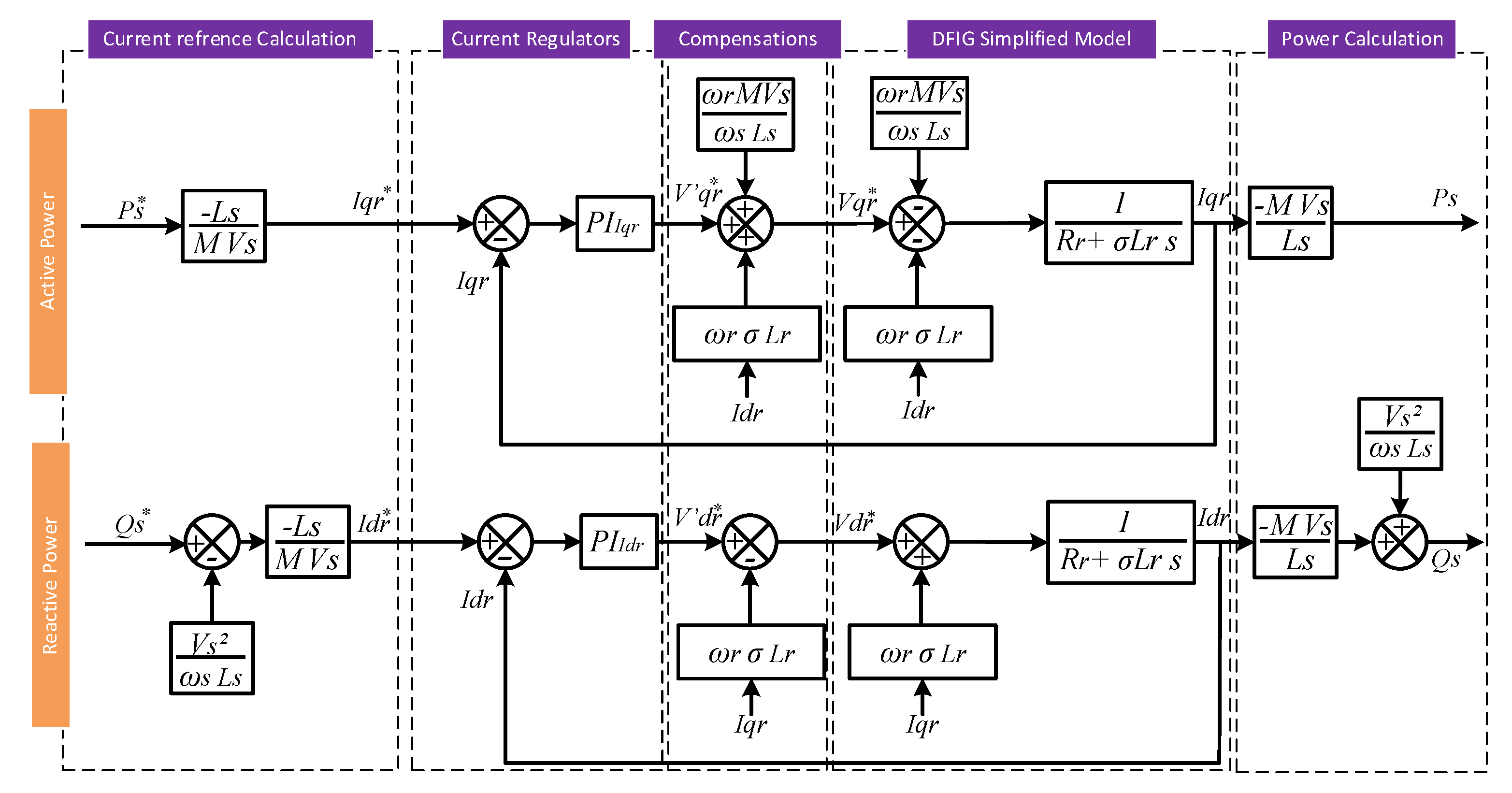
Figure 7.
WTE configuration with control system.
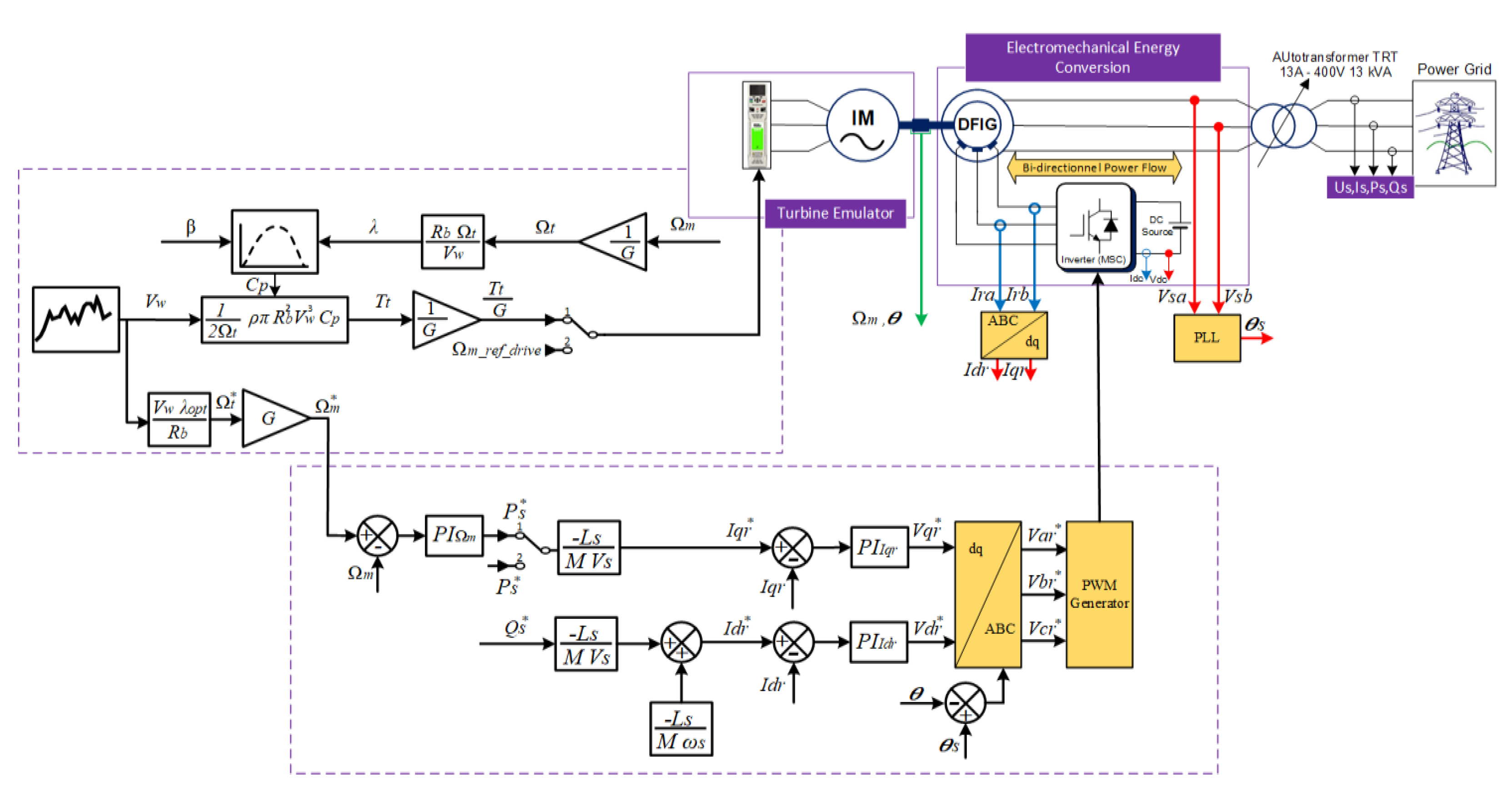
Figure 8.
Variable speed operation mode using a real wind speed profile.
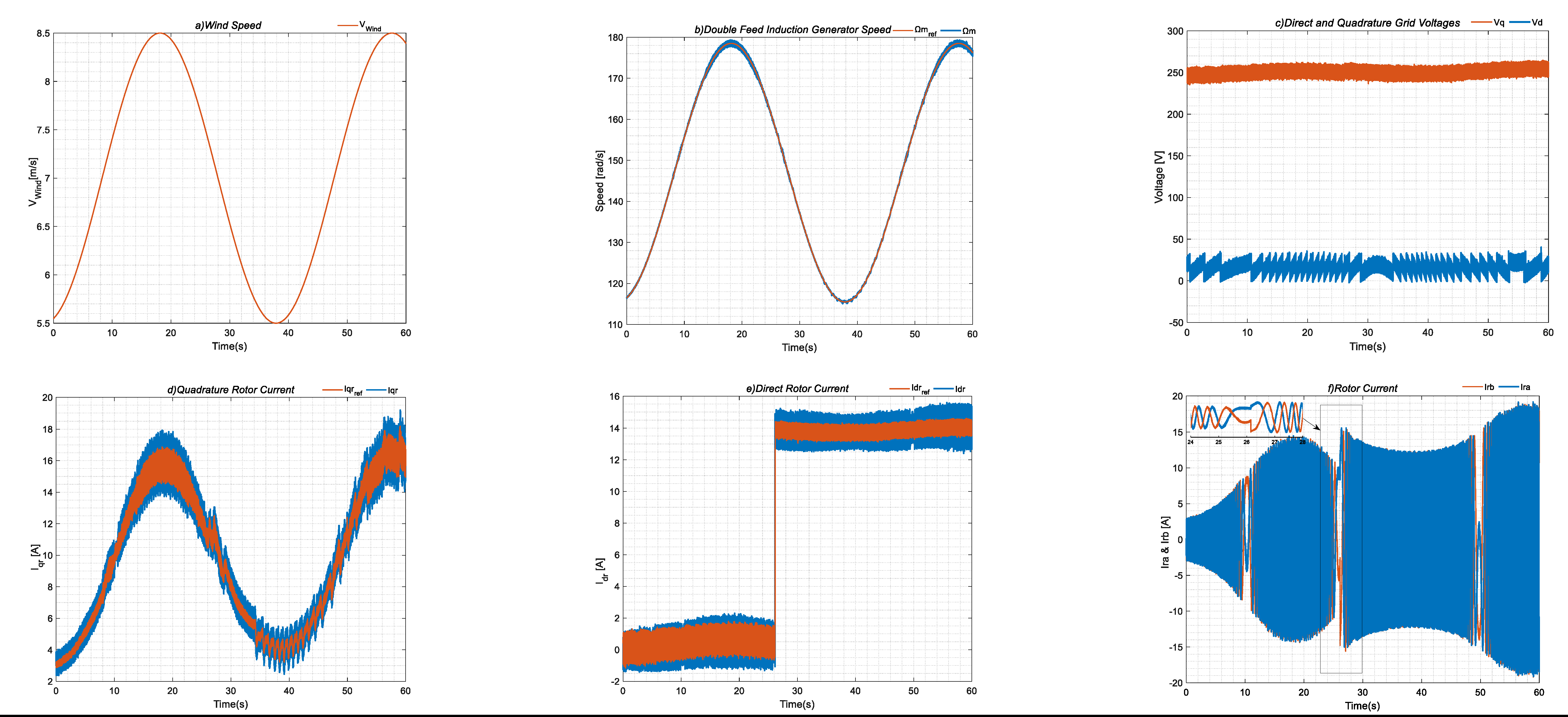
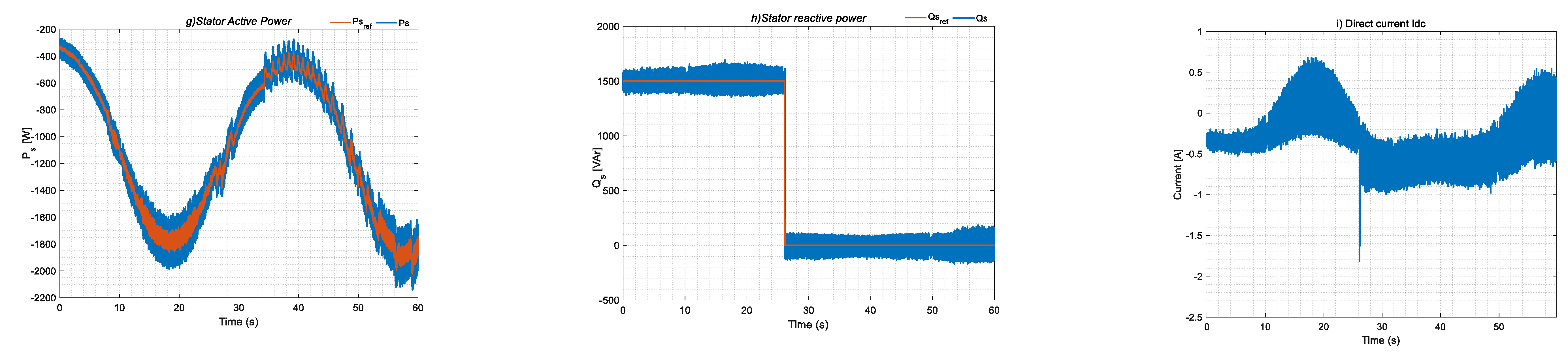

Table 1.
WTE Parameters.
| Symbol | Parameter | Value | Unit |
|---|---|---|---|
| DFIG Parameters (Rated Power 3 kw) | |||
| fs | Switching Frequency | 10 | kHz |
| P | Pairs of Poles | 2 | - |
| Rs | Stator resistance | 2.3 | Ω |
| Rr | Rotor resistance | 0.26 | Ω |
| Ls | Stator inductance | 0.128 | H |
| Lr | Rotor inductance | 0.029 | H |
| M | Mutual inductance | 0.0577 | H |
| J | Inertia | 0.1525 | kg·m² |
| F | Friction factor | 0.0055 | N·m·s |
| U1/U2 | Transformation Ratio | 0.23 | - |
| Wind Turbine Emulator Parameters (Rated Power 3kw) | |||
| Rb | Blade radius | 3 | meter |
| Air density | 1.225 | kg/m³ | |
| G | Gear box coefficient | 8 | - |
| β | Blade pitch angle | 2° | Degree |
| Control Parameters | |||
| Kp_I | Current Proportional gain | 4.7 | - |
| Ki_I | Current integral gain | 0.8 | - |
| Kp_PLL | PLL Proportional gain | 0.5 | - |
| Ki_PLL | PLL integral gain | 0.03 | - |
| Kp_Ω | Speed Proportional gain | 45 | - |
| Ki_ Ω | Speed integral gain | 4 | - |
Disclaimer/Publisher’s Note: The statements, opinions and data contained in all publications are solely those of the individual author(s) and contributor(s) and not of MDPI and/or the editor(s). MDPI and/or the editor(s) disclaim responsibility for any injury to people or property resulting from any ideas, methods, instructions or products referred to in the content. |
© 2025 by the authors. Licensee MDPI, Basel, Switzerland. This article is an open access article distributed under the terms and conditions of the Creative Commons Attribution (CC BY) license (http://creativecommons.org/licenses/by/4.0/).
Copyright: This open access article is published under a Creative Commons CC BY 4.0 license, which permit the free download, distribution, and reuse, provided that the author and preprint are cited in any reuse.


