Submitted:
04 November 2025
Posted:
05 November 2025
You are already at the latest version
Abstract
This study presents the development and performance evaluation of a biogas-powered electricity generation system designed for medium-scale swine farms. A conventional Hino V-22C diesel engine was modified to operate under spark-ignition mode using purified biogas as the primary fuel. The compression ratio was reduced from 18.5:1 to 14.7:1 to accommodate the lower heating value and slower flame speed of biogas. An Emergency Fuel Supply (EFS) system, automatically controlled by an oxygen sensor, was integrated to improve combustion stability during transient or high-load operations. Experimental tests were conducted to determine key thermodynamic and operational parameters including thermal efficiency, brake power, volumetric efficiency, and brake mean effective pressure. The generator achieved an electrical output of 80–120 kW, with the highest thermal efficiency of 11.66% at 100 kW under dual-fuel operation. The EFS system increased efficiency by approximately 22.7%, demonstrating its effectiveness in enhancing ignition quality and reducing cyclic variation. A techno-economic analysis was also carried out to assess the feasibility of implementing the system in a real swine farm. Results show that a farm housing 700 pigs per barn (six barns total) can produce approximately 30 kWh per housing unit, achieving a breakeven period of 15.79 months. The system not only provides a sustainable and cost-effective energy source but also reduces methane emissions from manure management, contributing to circular economy practices and greenhouse gas mitigation. Overall, the developed biogas generator demonstrates promising potential as a reliable, economically viable, and environmentally friendly decentralized power system for agricultural applications.
Keywords:
biogas generator
; spark ignition modification
; emergency fuel supply
; engine performance
; economic feasibility
; swine farm
1. Introduction
The demand for sustainable and renewable energy sources in the agricultural sector has steadily increased, driven by rising energy costs and environmental concerns. Livestock farms, particularly swine farms, produce substantial amounts of organic waste, including manure and wastewater, which can be effectively utilized as a renewable energy resource through biogas production. Biogas, primarily composed of methane (CH₄), offers a promising alternative to conventional fossil fuels due to its availability, low cost, and potential for reducing greenhouse gas emissions [1,2,3,4,5].
Converting biogas into electricity provides a dual benefit: it supports on-site energy generation while simultaneously improving waste management practices. However, the direct use of biogas in conventional diesel engines poses technical challenges, including low calorific value, slow flame propagation, and variable gas composition, which can reduce engine performance and thermal efficiency. Engine modifications, such as adjusting the compression ratio, implementing spark ignition systems, and optimizing fuel delivery, are therefore essential to ensure stable operation and high efficiency.
Recent studies have explored biogas-powered engines for small- and medium-scale agricultural applications, demonstrating the feasibility of integrating renewable energy systems into livestock operations. Despite these advances, the practical implementation of biogas generators in swine farms remains limited, particularly in terms of reliable power generation under fluctuating loads and economic feasibility.
This study presents the development and field testing of a biogas-powered generator specifically designed for medium-to-large-scale swine farms in Thailand. The system incorporates key innovations, including a modified diesel engine for biogas combustion, an emergency fuel supply system with oxygen-sensor-based automatic control, and an electric motor-assisted starter. The primary objectives are to evaluate engine performance, energy efficiency, and economic viability, providing a practical solution for sustainable on-farm electricity generation.
2. Materials and Methods
2.1. System Overview
The developed system comprises a modified Hino V-22C V10 diesel engine (21,548 cc, 420 hp), configured to run on biogas generated from pig manure and wastewater. The engine was coupled with a 250 kVA (200 kW) three-phase alternator (LEROR-SOMER Model TAL A46) delivering 380/220V at 50 Hz and 1500 rpm.
Engine Modification for Biogas Utilization
To successfully use biogas as fuel in diesel engines, comprehensive engine modifications are essential to ensure optimal functionality. The primary goal of these adaptations is converting a standard diesel engine, which operates through compression ignition, into one capable of spark ignition. The required modifications include [6,7,8,9,10,11,12,13]:
• Drilling the Cylinder Head: This modification allows for the installation of a spark plug, serving as the ignition source for biogas, which has different combustion characteristics compared to diesel.
• Adjusting the Compression Ratio: The engine’s compression ratio must be optimized to align with the properties of gaseous fuels, thus enhancing combustion efficiency.
• Upgrading the Fuel Delivery System: Alterations to the fuel delivery system are necessary to ensure the consistent and precise supply of biogas to the engine.
These adjustments improve the engine's power output and operational stability, enabling it to function as a primary mover for generating electricity on-site. This setup creates a sustainable energy cycle that powers the pig farm and facilitates efficient waste reuse. The method demonstrates the vital role of technology in enhancing energy security within the agricultural sector while contributing to environmental stewardship.
2.2. Optimization of the Fuel Delivery System for Biogas Operation
Pressure Swing Adsorption (PSA) is a gas purification technique that relies on adsorbent materials to separate gases. The process alternates between high-pressure adsorption and low-pressure desorption, effectively generating a stream of purified gas. Recognized for its energy efficiency and cost-effectiveness, PSA is widely employed across various industries.
The separation is based on the adsorption kinetics of the Carbon Molecular Sieve (CMS) material. The CMS is a microporous carbon material with precisely controlled pore sizes. While CH4 molecules have a slightly larger kinetic diameter (∼3.82 Å) than N2 (∼3.64 Å) and O2 (∼3.46 Å), the primary separation mechanism relies on the rate of diffusion into the CMS pores. Due to their smaller size, N2 and O2 molecules can diffuse into the pores of the CMS much faster than the larger CH4 molecules. Figure 1 illustrates a mixed gas stream, containing CH4, N2, and O2, is fed into the bottom of the absorber vessel at high pressure. As the gas flows upward through the CMS bed, the smaller and faster-diffusing N2 and O2 molecules are preferentially adsorbed onto the internal surface of the CMS granules. The larger CH4 molecules, with their slower diffusion rate, pass through the CMS bed with minimal adsorption. The resulting gas stream exiting the top of the absorber, referred to as GreenGas is thus highly enriched in methane [14,15].
Figure 1.
illustrates a schematic representation of a Pressure Swing Adsorption (PSA) system utilized for the purification of biogas.
Figure 1.
illustrates a schematic representation of a Pressure Swing Adsorption (PSA) system utilized for the purification of biogas.

2.3. Conversion and Adaptation of Diesel Ignition System for Biogas Utilization
The conversion of an engine's ignition system from diesel to biogas involves a series of technical modifications to enable efficient utilization of biogas as the primary fuel source. Key modifications typically include adjustments to the fuel injection system, optimization of the compression ratio, and alterations to enhance air-fuel mixing. In addition, specialized components such as biogas injectors and storage systems must be integrated to support stable operation. This transition not only promotes sustainability through the use of renewable energy but also requires strict adherence to safety protocols and regulatory standards to ensure operational reliability and environmental compliance [16,17,18].
Engine Modification and Compression Ratio Adjustment
Mechanical modifications were performed to optimize engine performance and reduce emissions during biogas operation. The compression ratio was lowered from 18.5:1 to 14.7:1 to stabilize combustion for the lower-calorific biogas, slightly reducing power output but enhancing combustion efficiency and minimizing knocking. Piston head shaving was precisely applied to achieve the target clearance volume, promoting smoother combustion and improved thermal performance.
The displacement volume (Vd) and compression ratio (rc) were calculated using the following relations:
The difference in clearance volume (ΔVc) before and after modification is expressed as:
The piston head shaving distance (Ds) was obtained from:
Where:
rc = Static Compression Ratio
Ds = Piston Head Shaving Distance
Vd = Displacement Volume
Vc = Clearance Volume
ΔVc = Difference of Clearance Volume Between Before and After
B = Diameter of Piston (Bore)
L = Engine Stroke
Table 1 summarizes the key experimental parameters and calculated results for the engine modification aimed at optimizing the compression ratio for biogas operation. The original diesel engine had a compression ratio of 18.5:1, which was reduced to 14.7:1 through a precise piston head shaving process, with a shaving distance of 10.36 mm. The piston diameter and stroke length were 139 mm and 142 mm, respectively, resulting in a displacement volume of 2,153,711 mm³. Correspondingly, the clearance volume increased from 123,069 mm³ before modification to 157,205 mm³ after modification. These adjustments were critical to achieving stable spark-ignition combustion with biogas, improving thermal efficiency, and mitigating knocking, while maintaining the overall mechanical integrity of the engine.

Table 1.
Experimental Data and Calculated Results for Engine Modification and Compression Ratio Adjustment.
Table 1.
Experimental Data and Calculated Results for Engine Modification and Compression Ratio Adjustment.
| Parameter | Value |
| Compression Ratio (Before Modification) | 18.5 : 1 |
| Compression Ratio (After Modification) | 14.7 : 1 |
| Piston Diameter, Dp (mm) | 139 |
| Stroke Length, L (mm) | 142 |
| Displacement Volume, Vd (mm³) | 2,153,711 |
| Clearance Volume (Before), Vc_before (mm³) | 123,069 |
| Clearance Volume (After), Vc_after (mm³) | 157,205 |
| Piston Head Shaving Distance, Ds (mm) | 10.36 |
Optimization of the Engine Ignition System for Biogas Combustion
The process of modifying the cylinder includes three key steps: first, removing the injector; second, threading the spark plug; and finally, installing the piston position sensor [19,20,21].
The modification process of the cylinder. The steps involve removing the injector, threading the location designated for the spark plug, and installing the piston position sensor to enhance functional integration, as illustrated in Figure 2.
Figure 2.
illustrates the modification process for the cylinder, which involves removing the injector, threading the spark plug, and installing the piston position sensor.
Figure 2.
illustrates the modification process for the cylinder, which involves removing the injector, threading the spark plug, and installing the piston position sensor.

2.4. Development of an Emergency Fuel Port (EFP) with Oxygen Sensor-Based Automatic Control
Emergency Fuel Port (EFP) equipped with automated control functionality managed by an oxygen sensor
Emergency Fuel Port (EFP)
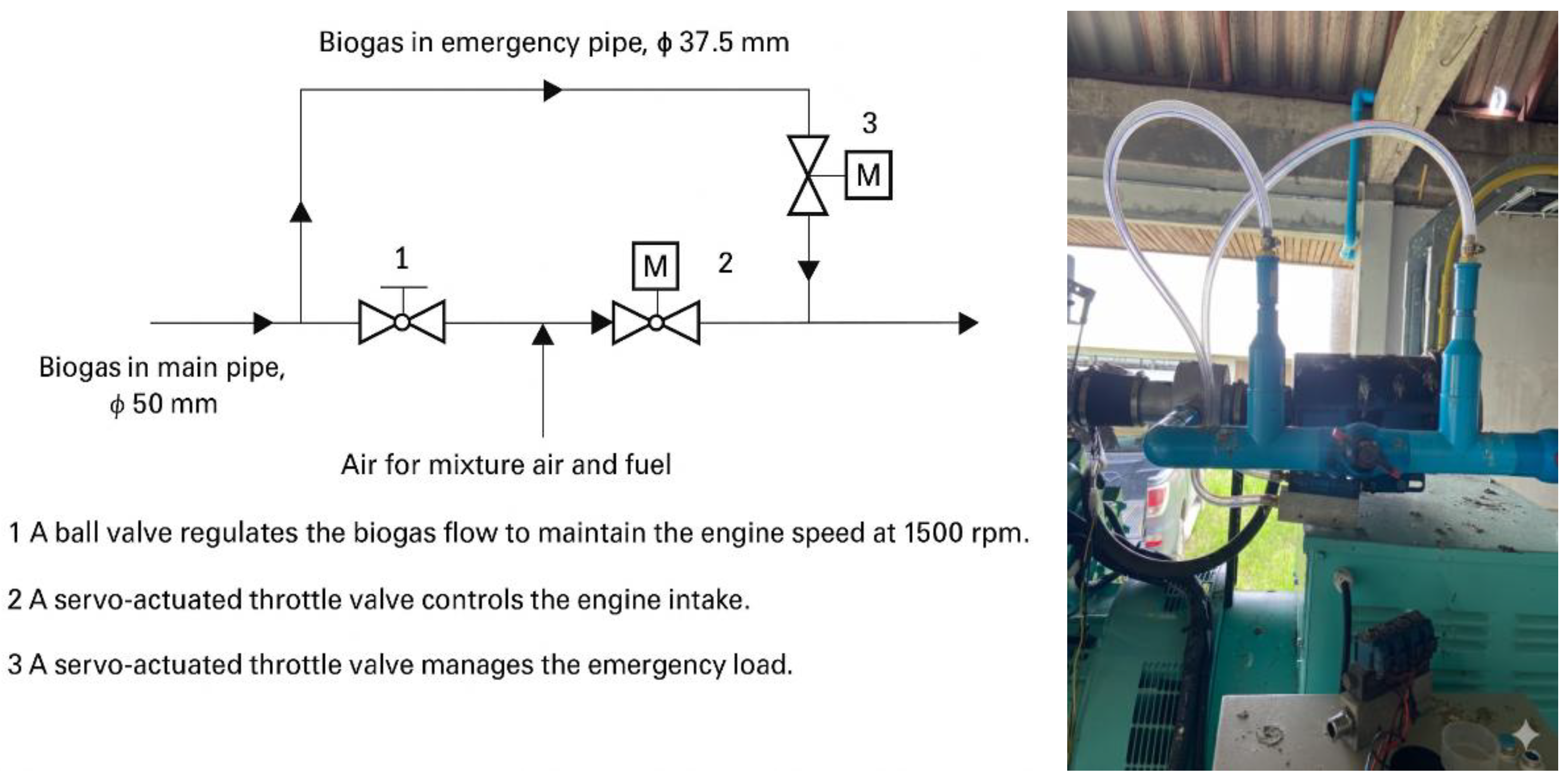
Figure 3 illustrates the detailed configuration of the biogas supply system. The system consists of a primary biogas line with an internal diameter of 50 mm, supplemented by an emergency bypass line of 37.5 mm in diameter. Before entering the engine intake, the biogas is premixed with intake air to ensure a homogeneous mixture, following the method described in previous studies [22,23,24].
Figure 3.
illustrates a schematic representation of the biogas–air mixing and emergency bypass system for engine operation.
Figure 3.
illustrates a schematic representation of the biogas–air mixing and emergency bypass system for engine operation.
The major components of the system are as follows:
1. Ball valve — regulates the biogas flow to maintain a constant engine speed of 1500 rpm.
2. Throttle valve — controls the air–biogas mixture flow rate entering the engine intake manifold.
3. Emergency throttle valve — activates during emergency load conditions, allowing additional biogas to pass through the bypass line.
Oxygen Sensor-Based Automatic Control
An automated system engineered for managing emergency fuel supply, functioning through the process of drilling into the exhaust pipe to install and integrate an oxygen sensor.
Figure 4 illustrates an automated control system designed for the emergency supply of fuel. This system operates by drilling into the exhaust pipe and integrating an oxygen sensor to regulate its functionality.
Figure 4.
illustrates an automated control system designed for emergency fuel supply. It operates by drilling into the exhaust pipe and integrating an oxygen sensor.
Figure 4.
illustrates an automated control system designed for emergency fuel supply. It operates by drilling into the exhaust pipe and integrating an oxygen sensor.
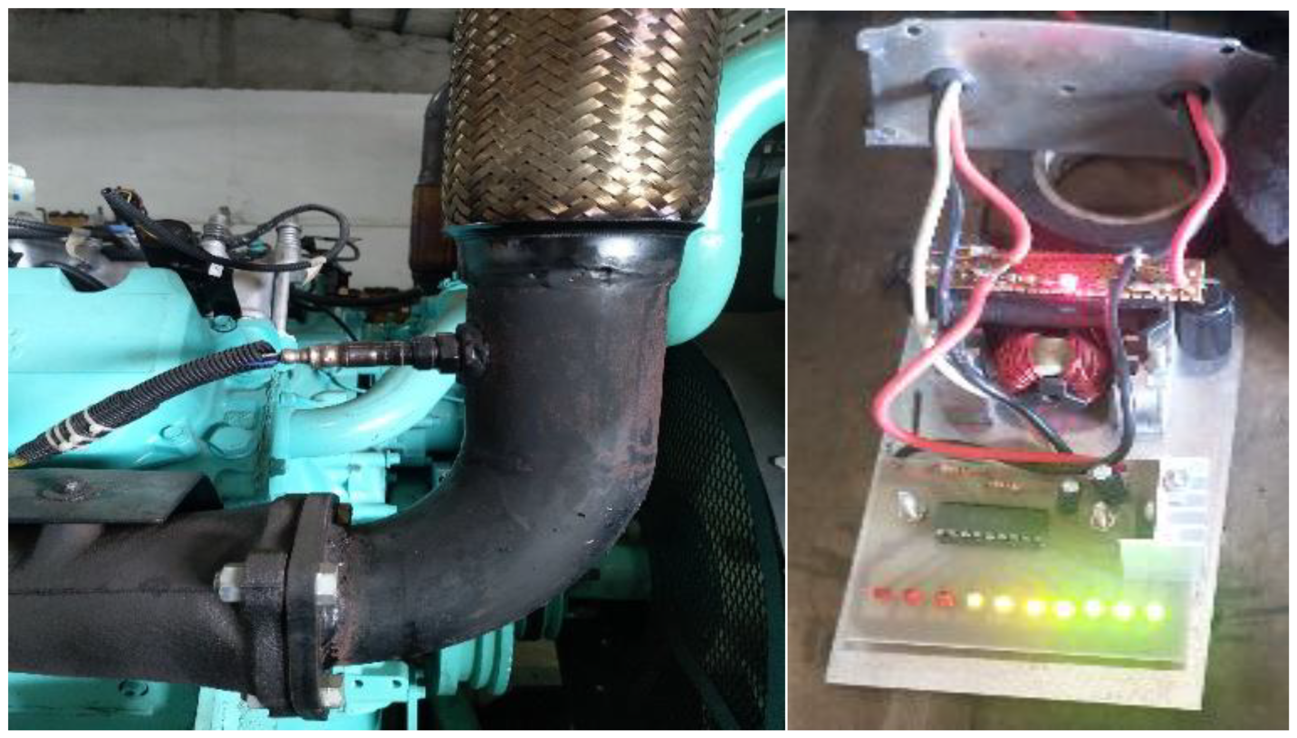
Table 2 presents the operational testing results of the power generation system equipped with an emergency fuel supply. The emergency fuel port is activated when the electrical load exceeds 80 kW to maintain stable engine operation. Engine radiator temperature, air-fuel ratio (λ), oxygen sensor output, and emergency valve opening are monitored under varying load conditions [25,26].
Table 2.
Operational Testing of Power Generation with Emergency Fuel Supply System.
| Description | Power Generation (kW) | ||||||
| 60 | 70 | 80 | 90 | 100 | 110 | 120 | |
| Electric Power (kW) | 60 | 70 | 80 | 90 | 100 | 110 | 120 |
| Engine Radiator Temperature (°C) | 62 | 64 | 65 | 70 | 70 | 74 | 85 |
| Air-Fuel Ratio (λ) | 17.2 | 17.4 | 17.5 | 17.5 | 17.5 | 17.3 | 17.2 |
| Oxygen Sensor Output (V) | 0.28 | 0.25 | 0.25 | 0.25 | 0.25 | 0.26 | 0.28 |
| Emergency Valve Opening (%) | 0 | 0 | 0 | 17 | 40 | 62 | 81 |
Notes: The emergency fuel supply system is activated when the electrical load exceeds 80 kW. Measurements were conducted under steady-state conditions for each load increment. Air–fuel ratio (λ) and O₂ sensor voltage indicate combustion efficiency and mixture quality.
2.5. Electric Motor-Based Starter System
This work presents a novel starting mechanism for internal combustion engines, integrating a manual-lever electrical motor. The design features an elongated starter-motor shaft, which is fitted with a pulley to receive power from an external electric motor via a belt drive. Additionally, the solenoid shaft is modified to include an extended hand lever. This configuration enables consistent and prolonged engine cranking, overcoming the operational limitations of conventional starting systems by utilizing a dedicated external power source [16,17,18].
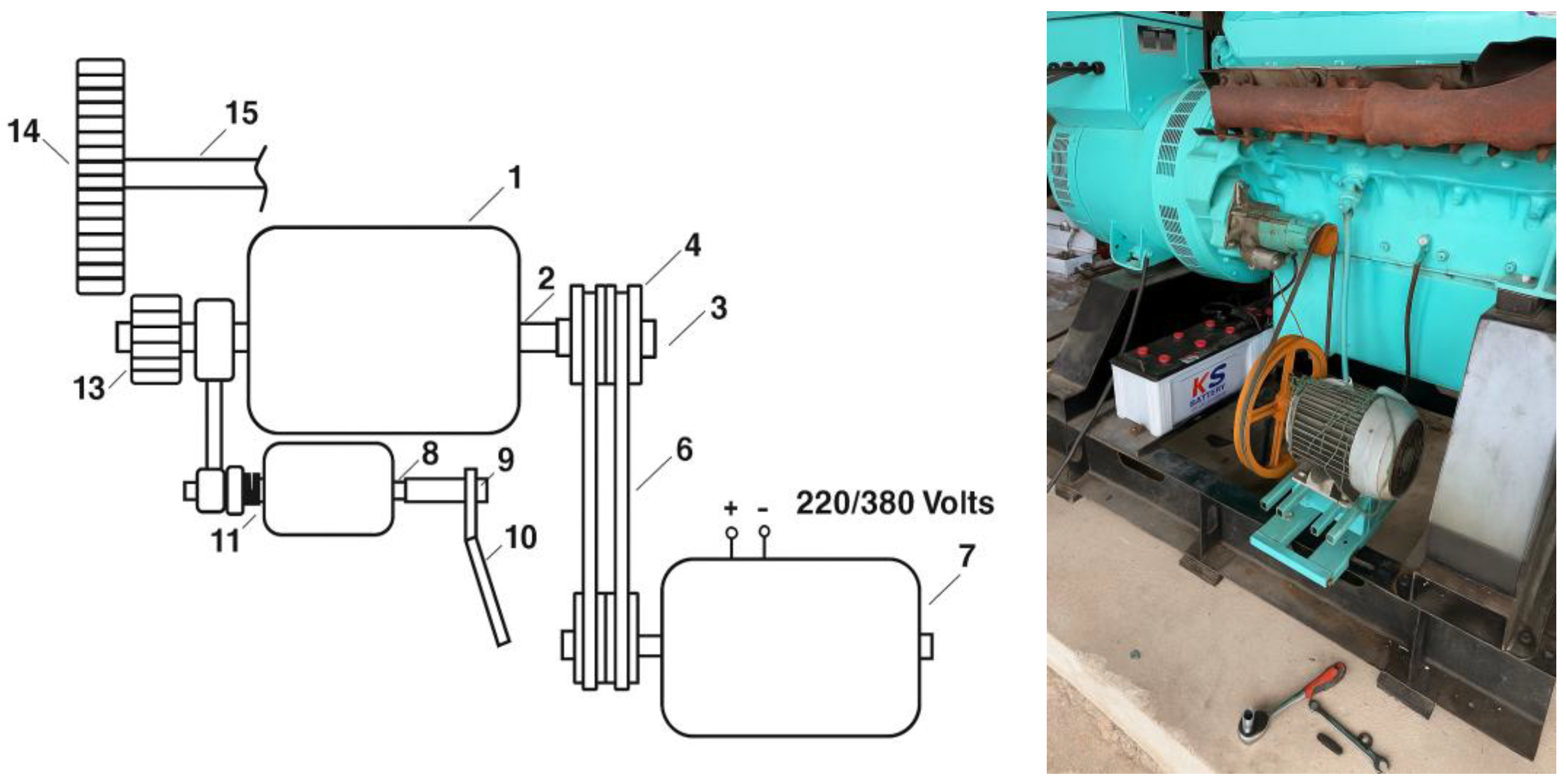
The system, comprising a starter motor equipped with a central shaft designed to rotate freely. One end of this shaft extends outward, featuring a pulley mounted on it. A belt connects this pulley, designated as pulley, to an adjacent pulley attached to the shaft of an electric motor, which functions on either a 220 V or 380 V power source. At the other end of the starter motor’s shaft, a drive-gear assembly is installed. This gear setup is connected via an arm to a spring-loaded solenoid mechanism. The solenoid’s shaft is extended further and includes a manual lever for operation. The drive-gear assembly can slide into position to engage with the flywheel gear, which is coupled directly to the crankshaft of the internal combustion engine. As illustrated in Figure 5, which shows the state before the internal combustion engine is started by the manual-lever electric motor, the manual lever has not been moved to the left. Consequently, the spring-loaded solenoid assembly remains stationary, and the drive-gear assembly does not engage with the flywheel gear. As a result, the internal combustion engine does not rotate and remains inactive.
Figure 5.
illustrates the configuration of a manual-lever electric starter prior to initiating the internal combustion engine. 1. Starter motor 2. Shaft 3. Shaft 4. Pulley 5. Pulley 6. Belt 7. Electric motor 8. Solenoid shaft 9. Extended shaft 10. Manual lever 11. Spring-loaded solenoid unit 12. Arm 13. Drive-gear assembly 14. Flywheel gear 15. Crankshaft.
2.6. Installation and Testing
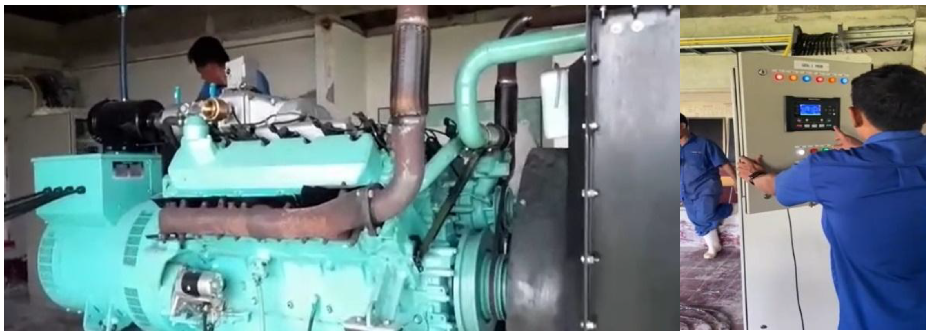
A comprehensive field study was carried out at a pig farming facility in Buriram, Thailand, to evaluate the operational performance of the system under real-world conditions, as illustrated in Figure 6. Key performance indicators, including engine stability, power generation efficiency, startup reliability, and thermal efficiency, were thoroughly examined. The study covered an extensive duration of 524 hours, during which data was systematically gathered and analyzed to provide precise insights into the system’s functionality.
Figure 6.
illustrates the operational testing of a diesel engine paired with a generator.
3. Results and Discussion
3.1. Performance Evaluation
The thermodynamic performance of the biogas-fueled internal combustion engine was evaluated using fundamental engine performance equations. The main parameters analyzed include thermal efficiency, brake power, indicated power, volumetric efficiency, and brake mean effective pressure. Experimental data and the corresponding calculations are summarized in Table 3.
Table 3.
Summary of experimental data and calculated performance parameters.
| Parameter | Symbol | Value | Unit |
| Electrical Power Output | P | 80 | kW |
| Fuel Consumption | 0.036 | kg/s | |
| Air Consumption | 0.63 | kg/s | |
| Thermal Efficiency | 0.095 | 9.5% | |
| Break Power | bp | 100.66 | kW |
| Indicated Power | 125.83 | kW | |
| Volumetric Efficiency | 0.82 | 82% | |
| Break Mean Effective Pressure | pmb | 3.74 | bar |
This relatively low efficiency is mainly due to the low heating value and slow flame propagation characteristics of biogas, which result in incomplete combustion and reduced temperature rise within the combustion chamber. Similar findings have been reported by Surendra and Nguyen [27,28], who observed that small-scale biogas engines generally operate within 8–15% thermal efficiency depending on gas purity and ignition optimization.
3.2. Thermal Efficiency
The thermal efficiency (ηₜₕ) represents the ratio between the useful output power and the energy supplied by the fuel. It is determined from the following equation:
where P is the electrical power output (kW), ṁf is the fuel mass flow rate (kg/s), K is the number of cylinders, and HHV is the higher heating value of the biogas (kJ/kg).
By substituting the measured data (P = 80 kW, ṁf = 0.036 kg/s, K = 10, HHV = 2330 kJ/kg), the thermal efficiency was found to be 9.5%.
3.3. Brake and Indicated Power
The brake power (bₚ) and indicated power (iₚ) were determined using the following relationships:
With ṁf = 0.36 kg/s, ηth = 0.12, HHV = 2330 kJ/kg, and mechanical efficiency (ηm) = 0.8, the calculated brake power and indicated power were 100.66 kW and 125.83 kW, respectively. The ratio between brake and indicated power confirms that approximately 20% of the energy is lost to friction and mechanical components, which is consistent with typical performance of naturally aspirated spark-ignition biogas engines.
3.4. Air Consumption and Volumetric Efficiency
Air consumption was calculated using Equation:
where ρₐ is the air density (1.15 kg/m³) and (A/F) is the air–fuel ratio by weight. The calculated air flow rate was 5.25 m³/s.
Volumetric efficiency (ηv) was derived from the actual air flow rate and the theoretical displacement volume, as expressed in Equation:
The resulting volumetric efficiency was 82%, which indicates effective air induction performance. This level of volumetric efficiency is typical for engines operating under atmospheric intake pressure without turbocharging [29].
3.5. Brake Mean Effective Pressure (BMEP)
The brake mean effective pressure (pmb) was determined from Equation:
where L is the stroke length, A is the piston area, N is the engine speed (revolutions per second), and K is the number of cylinders. The calculated value was 3.74 bar, which falls within the normal operating range for medium-load spark-ignition engines. The BMEP provides a useful indication of the engine’s capacity to convert cylinder pressure into mechanical work, and the obtained result suggests efficient combustion dynamics under biogas fueling.
3.6. Performance Analysis of the Emergency Fuel Supply System
The emergency fuel supply system was designed to automatically compensate for fuel shortage or instability during biogas operation by injecting an auxiliary fuel flow into the engine intake. The system’s performance was evaluated at five operating loads, ranging from 80 to 120 kW. The results are presented in Table 4.
Table 4.
Results of the emergency fuel supply system operation.
| Description | Result | ||||
| Electric Power Output (kW) | 80 | 90 | 100 | 110 | 120 |
| Fuel Consumption (kg/s) | 0.036 | 0.036 | 0.036 | 0.036 | 0.036 |
| Additional Fuel Consumption (kg/s) | 0 | 0.005 | 0.008 | 0.0126 | 0.0164 |
| Thermal Efficiency of Engine (%) | 9.50 | 10.58 | 11.66 | 9.71 | 9.83 |
At a baseline load of 80 kW, the engine operated solely on biogas with a fuel consumption rate of 0.036 kg/s, achieving a thermal efficiency of 9.5%. As the electrical load increased, a small portion of additional fuel (ranging from 0.005 to 0.0164 kg/s) was supplied automatically to stabilize combustion and maintain power output. The maximum efficiency of 11.66% was observed at 100 kW, which corresponds to an optimal mixture condition where the supplementary fuel improved the combustion completeness and flame propagation rate.
Beyond this point (110–120 kW), the efficiency slightly declined to around 9.8%, likely due to over-enrichment of the fuel mixture and higher exhaust gas temperature. This trend indicates that while the emergency fuel system effectively enhances combustion stability and performance under medium to high load, excessive auxiliary fuel addition does not proportionally increase efficiency.
3.6. Overall Performance Discussion
The overall performance evaluation of the biogas-fueled power generation system, including the emergency fuel supply system (EFS), demonstrates that the engine can maintain stable operation across a wide range of loads with moderate energy conversion efficiency. Under baseline conditions operating solely on biogas, the generator delivered 80 kW of electrical output at a thermal efficiency of 9.5%. This performance aligns with typical results of small-scale spark-ignition biogas engines, where low heating value and slow flame propagation of biogas tend to limit thermal efficiency [28,30].
When the EFS was activated, supplementary fuel was automatically injected during higher load demands (90–120 kW) to compensate for biogas quality fluctuations and enhance combustion stability. The additional fuel flow ranged from 0.005 to 0.0164 kg/s, depending on load conditions. This mechanism significantly improved engine performance, with maximum thermal efficiency reaching 11.66% at 100 kW, representing an approximate 22.7% improvement over the pure-biogas operation.
The observed increase in efficiency at moderate loads can be attributed to better air–fuel mixing and enhanced flame propagation due to the supplemental fuel, which results in more complete combustion and reduced cyclic variation. However, when the electrical load exceeded 100 kW, efficiency slightly decreased to around 9.8%, likely caused by over-enrichment of the mixture and higher exhaust temperatures, which increase unburned fuel losses. This finding corresponds with results from Patel et al. (2020), who reported that excessive enrichment in biogas–gasoline dual-fuel operation yields diminishing efficiency gains.
The integration of the EFS therefore provides two key advantages:
1. Operational stability under variable gas supply or composition, reducing engine misfire risk and power fluctuation.
2. Performance enhancement, particularly within mid-range loads where combustion quality is most sensitive to fuel-air equivalence ratio.
Overall, the system achieved stable electricity generation up to 120 kW output, maintaining an acceptable balance between fuel efficiency and reliability. The combination of biogas as the primary fuel and a controlled supplementary fuel supply offers a practical and sustainable approach for decentralized renewable power generation, particularly in agricultural or rural regions where biogas composition may vary over time.
3.7. Evaluation of the Biogas Power Generator Implementation in a Swine Farm
Suitability of the Power Generation System for Swine Farm Applications
The feasibility assessment of the biogas-based power generator was conducted at a commercial swine farm to determine its suitability for agricultural-scale renewable energy utilization. The results, summarized in Table 5, indicate that the system is appropriately sized for the farm’s energy demand and available biogas resources.
Table 5.
Suitability of the biogas generator system for swine farm applications.
| Description | Result | Remark |
| Suitability for electricity production | ✓ | One housing unit with 700 pigs can generate 30 kWh of electrical power. |
| Generator cost | 15,000 THB/kWh | Estimated average including equipment and installation. |
Under practical operating conditions, the farm housing 700 pigs per barn could continuously generate approximately 30 kWh of electrical power. This corresponds well with the available biogas yield derived from manure management within a single housing unit. The investment cost of the biogas generator, including installation and auxiliary equipment, was approximately 15,000 THB per kWh of installed capacity, representing a reasonable cost level for decentralized power systems of this scale [32,33].
These findings confirm that the generator capacity is appropriately matched to the farm’s biogas potential and electricity needs, making it a technically viable solution for rural or off-grid power generation.
Economic Feasibility and Breakeven Analysis
An economic assessment was carried out to evaluate the payback period of the installed biogas generator system when operated as a substitute for electricity from the Provincial Electricity Authority (PEA). The cost–benefit analysis results are shown in Table 6.
The system’s fixed investment cost (generator and installation) was 1,500,000 THB, with monthly variable costs comprising:
- Labor: 24,000 THB (two operators at 12,000 THB each per month),
- Routine maintenance and spare parts: 5,000 THB/month,
- Scheduled servicing of engine and gas system: 4,000 THB/month (based on 12,000 THB every three months).
The total monthly operating cost was therefore 33,000 THB. The average monthly electricity generation was estimated at 128,000 THB, based on:
80 kWh×20 h/day×30 days×8 mouths/year×4 THB/kWh = 1,536,000 THB/year
which corresponds to 128,000 THB/month.
By equating cumulative production cost and cumulative revenue, the breakeven point is reached at 15.79 months, indicating that the initial investment can be fully recovered within approximately 1 year and 4 months of continuous operation.
Table 6.
Breakeven analysis of the biogas power generator for swine farm application.
| Parameter | Details/Remarks |
| Fixed Cost | 1,500,000 THB (equipment + installation) |
| Variable Cost per Month | Labor: 24,000 THB; Spare parts: 5,000 THB; Service: 4,000 THB → 33,000 THB/month |
| Monthly Revenue | 128,000 THB (based on 80 kWh generation, 4 THB/kWh) |
| Breakeven Point (X) | 1,500,000+33,000X=128,000X → X = 15.79 months |
| Farm Information | 6 barns, 700 pigs per barn, 120 kVA generator, 8 months of annual operation |
The analysis demonstrates that the biogas power generator not only provides a sustainable electricity source but also yields a rapid payback period, confirming its economic feasibility for medium-scale livestock farms. Moreover, the integration of waste-to-energy systems promotes circular economy practices by converting animal manure into usable energy, reducing both waste disposal and electricity costs [34,35].This section may be divided by subheadings. It should provide a concise and precise description of the experimental results, their interpretation, as well as the experimental conclusions that can be drawn.
4. Conclusions
The findings from this study highlight the significant technical and economic potential of biogas-based power generation systems for medium-scale swine farms. The modified Hino V-22C diesel engine demonstrated stable operation when fueled primarily with purified biogas, producing up to 120 kW of continuous power. Although the overall thermal efficiency ranged between 9.5–11.7%, which is lower than that of conventional diesel engines, this performance is consistent with previous studies reporting efficiencies of 8–15% for small-scale biogas engines under spark-ignition operation [27,28,29]. The reduced efficiency can be attributed to the low heating value and slow flame propagation rate of biogas, leading to incomplete combustion and lower in-cylinder pressure development.
However, the inclusion of the Emergency Fuel Supply (EFS) system significantly improved combustion stability and operational reliability. When the system automatically supplied auxiliary fuel under high-load conditions, the thermal efficiency increased by approximately 22.7%, peaking at 11.66% at 100 kW. This improvement aligns with the findings of Patel et al. [31] and Mohanraj et al. [20], who reported that limited secondary fuel enrichment can enhance flame propagation and reduce cyclic variation in dual-fuel biogas systems. Nevertheless, efficiency declined slightly beyond 100 kW due to mixture over-enrichment and heat losses, suggesting the need for further optimization of the oxygen-sensor control algorithm to balance air–fuel ratios dynamically.
The engine modification process, including compression ratio adjustment from 18.5:1 to 14.7:1, played a crucial role in ensuring stable ignition and smooth combustion of biogas. The reduced compression ratio mitigated knocking tendencies commonly observed in gaseous fuels with high methane content, corroborating the results of Nguyen and Nguyen [18] and Belgiorno et al. [16]. Moreover, the installation of a spark-ignition system and sensor integration improved engine controllability and combustion repeatability, making the configuration well-suited for distributed power generation.
The economic evaluation reinforces the technical viability of the system. With a total investment of 1.5 million THB and monthly operating costs of 33,000 THB, the system achieved a breakeven period of 15.79 months, which is shorter than the 18–24 months typically reported in similar livestock-based biogas-to-power projects [33,34,35]. This rapid return on investment stems from the system’s capacity to offset electricity expenses from the Provincial Electricity Authority (PEA), producing an estimated 128,000 THB/month in energy value. The results align with the techno-economic findings of Singh et al. [33], who noted that decentralized biogas systems can provide attractive payback periods under favorable operating conditions.
From an environmental standpoint, the developed system contributes to greenhouse gas reduction by utilizing methane that would otherwise be released from open-lagoon manure management. The approach supports a circular economy model by converting livestock waste into usable energy while reducing dependency on fossil fuels and minimizing odor and wastewater pollution [1,13,34]. When scaled across similar farms, such systems can enhance rural energy security, reduce grid dependency, and support Thailand’s national bioenergy development roadmap.
Overall, the research demonstrates that integrating biogas purification, optimized ignition modification, and adaptive fuel control can yield a technically stable, economically viable, and environmentally sustainable power generation solution for agricultural sectors. Further research should focus on enhancing combustion control through real-time gas composition monitoring and adaptive ignition timing to maximize efficiency under fluctuating biogas quality.
Acknowledgments
The authors would like to express their sincere gratitude to Pattanakit 49 Engineering Co., Ltd. for providing materials, equipment, and technical labor support during this project. Special thanks are also extended to Ruckchai Trangkakul and the technical working team for their valuable guidance and assistance throughout the research. This work was financially supported by the Industrial Technology Assistance Program (ITAP) under the Khon Kaen University, Thailand Network, which greatly contributed to the successful completion of this study.
References
- Jameel, M.; et al. Biogas: Production, properties, applications, economic and challenges: A review. Results in Chemistry 2024, 7, 101549. [Google Scholar] [CrossRef]
- Leykun, M. G.; Walle, M. Investigation of the Performance and Emission Characteristics of Diesel Engine Fueled with Biogas-Diesel Dual Fuel. Fuels 2022, 3(1), 15–30. [Google Scholar] [CrossRef]
- Skibko, Z. Voltage problems on farms with agricultural biogas plants. Applied Sciences 2024, 14(16), 7003. [Google Scholar] [CrossRef]
- Canevesi, R. L. S.; et al. Pressure swing adsorption for biogas upgrading with carbon molecular sieve. Industrial & Engineering Chemistry Research 2018, 57(30), 9738–9745. [Google Scholar] [CrossRef]
- Chen, Y. F. Biogas upgrading by pressure swing adsorption with simulated data. Processes 2021, 9(8), 1325. [Google Scholar] [CrossRef]
- Radostin, D.; Z., P. Determination of the optimal air-fuel ratio for upgraded biogas engine operation. E3S Web of Conferences 2021, 327, 02009. [Google Scholar] [CrossRef]
- Verma, S.; et al. Effects of varying composition of biogas on engine performance. Fuel Processing Technology 2017, 162, 124–130. [Google Scholar] [CrossRef]
- Heywood, J. B. Internal Combustion Engine Fundamentals, 2nd ed.; McGraw-Hill, 2018. [Google Scholar]
- Montoya, J. P. G.; Arrieta, A. A. A.; Jaime, F.; Zapata Lopez, J. F Z. Experimental study of spark ignition engine performance and emissions in a high compression ratio engine using biogas and methane mixtures without knock occurrence. Thermal Science 2017, 19(00), 119–119. [Google Scholar] [CrossRef]
- Walle, M.; et al. Performance and emission analysis of a biogas–diesel dual-fuel engine; ACS Omega, 2025. [Google Scholar] [CrossRef]
- Palanivelrajan, A. R. Performance and emission characteristics of biogas fuelled stationary engines. Fuel Processing / Energy 2024. [Google Scholar] [CrossRef]
- Das, A. K.; Padhi, M. R.; Behera, D. D.; Das, S. S. Evaluation of a diesel engine performance and emission using biogas in dual fuel mode. Mechanical Engineering for Society and Industry 2024, 4(2), 167-176. [Google Scholar] [CrossRef]
- Gupta, P.; et al. Biogas (a promising bioenergy source): A critical review; Renewable & Sustainable Energy Reviews, 2023. [Google Scholar] [CrossRef]
- Ruthven, D. M.; Farooq, S.; Knaebel, K. S. Pressure Swing Adsorption. In VCH Publishers; 1994. [Google Scholar]
- Grande, C. A.; Rodrigues, A. E. Separation of methane and nitrogen by pressure swing adsorption using carbon molecular sieve. Separation Science and Technology 2005, 40(13), 2721–2743. [Google Scholar] [CrossRef]
- Belgiorno, G.; Di Blasio, G.; Beatrice, C. Parametric study and optimization of the main engine calibration parameters and compression ratio of a methane-diesel dual fuel engine. Fuel 222 2018, 821–840. [Google Scholar] [CrossRef]
- Ibrahim, A.; Al-Sulaiman, F. A. Optimizing a spark-ignition engine fuelled with methane: A numerical study. Frontiers in Thermal Engineering 2022, 1(1), 1–10. [Google Scholar] [CrossRef]
- Nguyen, Q. T.; Nguyen, T. T. Effects of compression ratios on combustion and emission characteristics of hydrogen-enriched biogas engines. MDPI Energies 2022, 15(16), 5975. [Google Scholar] [CrossRef]
- Samanta, A.; Das, S.; Roy, P. C. Performance analysis of a biogas engine. International Journal of Research in Engineering and Technology 2018. [Google Scholar]
- Mohanraj, T.; Rakesh, S.; Sudhakar, K.; Senthilvel, D. Performance and emission characteristics of a biogas engine with an improvised fuel supply system. Energy Sources, Part A: Recovery, Utilization, and Environmental Effects 2019, 41(19), 2321–2330. [Google Scholar] [CrossRef]
- Hassan, H.; El-Kassaby, R. Development and testing of a new control system for biogas engines. Alexandria Engineering Journal 2014, 53(1), 17–23. [Google Scholar] [CrossRef]
- Innova. Air-Fuel Ratio Sensor - How It Works. 21 December 2023. Available online: https://www.innova.com/blogs/fix-advices/air-fuel-ratio-sensor-how-it-works.
- Snap-on. Air/Fuel Ratio Sensor Test - Diagnostic Quick Tips', 2023. Available online: https://www.snapon.com/EN/US/Diagnostics/News-Center/Technical-Focus-Archive/Air-Fuel-Ratio-Sensor-Test.
- Bosch. Automotive handbook, 10th ed.; Robert Bosch GmbH, 2018. [Google Scholar]
- Heywood, J. B. Internal combustion engine fundamentals, 2nd ed.; McGraw-Hill Education, 2018. [Google Scholar]
- Shigley, J. E.; Mischke, C. R. Mechanical Engineering Design; McGraw-Hill, 2001. [Google Scholar]
- Surendra, K. C.; Takara, D.; Hashimoto, A. G.; Khanal, S. K. Biogas as a renewable energy source: A review. Biofuel, Bioproducts and Biorefining 2014, 8(6), 929–953. [Google Scholar] [CrossRef]
- Nguyen, M. T.; Hagos, D. A.; Matsumoto, T. Performance assessment of small-scale biogas-fueled generators for rural electrification. Renewable Energy 2021, 179, 1225–1236. [Google Scholar] [CrossRef]
- Kapdi, S. S.; Vijay, V. K.; Rajesh, S. K.; Prasad, R. Biogas scrubbing, compression and storage: Perspective and prospectus in Indian context. Renewable Energy 2005, 30(8), 1195–1202. [Google Scholar] [CrossRef]
- Singh, S. P.; Kalamdhad, A. S. Assessment of biogas production and power generation potential from organic waste in India. Renewable and Sustainable Energy Reviews 2018, 82, 760–772. [Google Scholar] [CrossRef]
- Patel, K. M.; Sharma, R.; Mehta, R. Dual-fuel operation of biogas engines using gasoline as pilot fuel: Performance and emission analysis. Energy Conversion and Management 2020, 226, 113487. [Google Scholar] [CrossRef]
- FAO. Biogas systems in livestock operations: Practical guidelines for developing countries; Food and Agriculture Organization of the United Nations, 2020. [Google Scholar]
- Singh, R.; Kumar, S.; Saini, R. P. Economic assessment of decentralized biogas-based power generation systems in rural India. Renewable Energy 2021, 173, 1050–1061. [Google Scholar] [CrossRef]
- Zhang, Y.; Luo, T.; Wang, X. Techno-economic analysis of biogas-to-power systems in livestock farms: Case study approach. Energy Reports 2020, 6, 527–535. [Google Scholar]
- Chen, Z.; Yang, L.; Li, Q. Economic and environmental performance of on-farm biogas electricity generation: A case study in Asia. Journal of Cleaner Production 2022, 338, 130579. [Google Scholar]
Disclaimer/Publisher’s Note: The statements, opinions and data contained in all publications are solely those of the individual author(s) and contributor(s) and not of MDPI and/or the editor(s). MDPI and/or the editor(s) disclaim responsibility for any injury to people or property resulting from any ideas, methods, instructions or products referred to in the content. |
© 2025 by the authors. Licensee MDPI, Basel, Switzerland. This article is an open access article distributed under the terms and conditions of the Creative Commons Attribution (CC BY) license (http://creativecommons.org/licenses/by/4.0/).
Copyright: This open access article is published under a Creative Commons CC BY 4.0 license, which permit the free download, distribution, and reuse, provided that the author and preprint are cited in any reuse.


