
Submitted:
31 October 2025
Posted:
03 November 2025
You are already at the latest version
Abstract
This study presents the design, real-time implementation, and full-scale experimental validation of a novel rule-based Energy Management Strategy (EMS) for a dual-stack Fuel Cell Hybrid Electric Vehicle (FCHEV) developed on a Jeep Wrangler platform. Unlike previous studies limited to simulations or single-stack configurations, this work experimentally demonstrates, for the first time, a deterministic real-time EMS for a dual fuel cell system in an SUV class vehicle. The control algorithm, deployed on a National Instruments CompactRIO embedded controller, ensures real-time energy distribution and stable hybrid operation under dynamic load conditions. Simulation analysis performed over eight consecutive WLTC cycles confirmed that both fuel cell stacks operated within their optimal efficiency range (25–35 kW), achieving an average DC efficiency of 68% and a hydrogen consumption of 1.35 kg/100 km. Experimental validation on the Wrangler FCHEV demonstrator yielded an equivalent hydrogen consumption of 1.67 kg/100 km, corresponding to 1.03 kg/100 km·m² after aerodynamic normalization (Cd·A = 1.624 m²), comparable to commercial fuel cell vehicles. The results demonstrate that the proposed EMS maintains over 80% of operating time within high-efficiency zones, reducing fuel cell cycling and enhancing durability. This work bridges the gap between theoretical EMS design and real-world embedded validation, establishing a scalable benchmark for future hydrogen powertrain control systems.
Keywords:
fuel cell hybrid electric vehicle (FCHEV)
; energy management strategy (EMS)
; rule-based control
; CompactRIO embedded controller
; hydrogen consumption
; power management
; WLTC
; real-world driving test
1. Introduction
Fuel cell hybrid electric vehicles (FCHEVs) represent one of the most promising technological pathways toward achieving zero-emission mobility and decarbonizing the transport sector. By combining the high energy density of hydrogen with the flexibility of electrochemical storage, FCHEVs offer extended driving range, fast refueling capability, and superior energy efficiency compared to pure battery electric vehicles (BEVs) — particularly for heavy-duty and off-road applications [1]. Recent advances in high-fidelity modeling, system control, and real-time validation have substantially improved the performance prediction accuracy of fuel cell systems (FCS) under realistic driving conditions [2]. Moreover, predictive and learning-based energy management strategies (EMS) have demonstrated significant potential in reducing hydrogen consumption and improving component durability, yet their real-time implementation on embedded automotive controllers remains limited [3]. Therefore, developing experimentally validated EMS solutions that ensure deterministic operation, robust performance, and scalability for multi-stack configurations has become a key research priority for the next generation of FCHEVs.
1.1. Current Challenges and Research Gap in Existing Literature
In recent years, FCHEVs have received increasing attention as viable solutions for sustainable mobility and carbon-neutral transportation. Despite significant progress in modeling, control, and EMS design, several challenges persist in bridging the gap between simulation-based studies and fully validated experimental platforms.
Existing literature presents a variety of EMS approaches — from rule-based control to optimization- and learning-based strategies — mostly verified through numerical simulations or hardware-in-the-loop (HIL) environments. However, few studies demonstrate complete experimental validation at the vehicle level, particularly for dual fuel cell systems operating under dynamic driving conditions. Moreover, most works rely on simplified fuel cell or battery models, neglecting the complex coupling among stack dynamics, balance of plant (BoP) subsystems, and the supervisory controller.
A careful examination of recent contributions (Table 1) reveals several recurring technical gaps:
- Many EMS algorithms are evaluated exclusively in simulation or using single-stack laboratory setups.
- Dynamic characteristics of BoP components (compressor, pump, humidifier, cooling circuit) are often neglected or idealized.
- The rule-based control frameworks, while robust and simple, lack adaptability to real-time disturbances and drive cycle variations.
- Optimization-based strategies (DP, ECMS, MPC) offer superior efficiency but exhibit high computational cost, preventing real-time deployment.
- Learning-based EMS (e.g., reinforcement learning, neural networks) show potential but remain data-intensive and difficult to interpret physically.
To summarize, there is a clear need for EMS approaches that combine physical transparency, computational tractability, and real-time feasibility, validated on real vehicles under transient driving conditions. Furthermore, current studies seldom address multi-stack coordination or embedded control implementation, which are key enablers for scaling FCHEVs toward higher power demands and improved system reliability.
From the studies summarized in Table 1, it is evident that:
- Real-time embedded control validation remains scarce in FCHEV literature.
- System-level experimental results are typically constrained to simplified or single-stack systems.
- There is a lack of integrated EMS designs accounting for BoP and multi-stack dynamics.
Hence, this study aims to fill these research gaps by developing and experimentally validating an online Energy Management Strategy implemented on an NI CompactRIO controller for a dual fuel cell hybrid electric vehicle, ensuring deterministic control and real-time operability under dynamic load transitions.
1.2. Research Objectives and Main Contributions
The main objective of this research is to develop and experimentally validate an online Energy Management Strategy (EMS) implemented on an NI CompactRIO embedded controller for a Jeep Wrangler dual fuel cell hybrid electric vehicle (FCHEV). Unlike many previous studies that rely exclusively on simulation or HIL environments, this work demonstrates real-time coordination of two independent fuel cell stacks through a rule-based supervisory controller operating under realistic driving conditions.
To achieve this main goal, the study pursues the following specific objectives:
- Develop a dual fuel cell coordination algorithm capable of dynamically managing the load distribution between two proton exchange membrane (PEM) stacks to ensure balanced operation, reduced current stress, and extended lifetime.
- Design and implement a rule-based Energy Management Strategy (EMS) on a National Instruments CompactRIO real-time controller, ensuring deterministic execution and robust stability through the LabVIEW/VeriStand environment.
- Integrate the EMS into the vehicle’s hybrid powertrain, including the dual fuel cell system, DC/DC converters, traction motor, and lithium-ion battery pack, ensuring seamless communication and energy flow.
- Define and calibrate the operating regions (Z0–Z6) of the EMS to cover the full spectrum of vehicle power demand and state-of-charge (SoC) variations under both transient and steady-state conditions.
- Perform comprehensive simulation and experimental validation of the FCHEV prototype, quantifying hydrogen consumption, SoC stability, dynamic response, and overall system efficiency under representative WLTC and real-world driving cycles.
- Assess the impact of dual-stack operation on hydrogen economy, energy efficiency, and system reliability, and benchmark the obtained results against conventional single-stack configurations and recent state-of-the-art EMS frameworks.
- Demonstrate real-time feasibility and scalability of the proposed EMS for embedded automotive deployment in next-generation fuel cell hybrid platforms.
Main Contributions
The key scientific and technical contributions of this study are summarized as follows:
- Novel dual-stack EMS architecture — One of the first experimentally validated real-time energy management systems for a dual fuel cell configuration in an SUV-class vehicle, enabling scalable power distribution and improved system redundancy compared to traditional single-stack topologies.
- Deterministic real-time embedded validation — The EMS was implemented and executed on a National Instruments CompactRIO platform with 1 ms cycle control, confirming the feasibility of real-time onboard operation for automotive-grade applications.
- Adaptive and computationally efficient energy distribution — The proposed rule-based logic dynamically coordinates power sharing between fuel cell stacks and the lithium-ion battery, maintaining SoC stability without requiring optimization or predictive algorithms.
- Comprehensive experimental verification under dynamic load conditions — The EMS was validated both in simulation and on a full-scale FCHEV demonstrator, achieving an average fuel cell DC efficiency of 68% and a hydrogen consumption of 1.67 kg/100 km under real driving conditions.
- Advancement of the state of the art — This work provides new experimental evidence supporting real-time EMS implementation for dual-stack architectures, filling a critical research gap between model-based design and practical vehicle-level validation.
Methodology for future EMS upgrades — The study establishes a foundation for integrating additional subsystems (e.g., regenerative braking, ultracapacitor support, or predictive control layers) within the same real-time framework.
Through these objectives and contributions, the study bridges the existing gap between theoretical EMS design and practical embedded implementation for FCHEVs. By focusing on deterministic real-time control, dual-stack coordination, and experimental validation, the proposed EMS provides a scalable and reliable supervisory framework for next-generation hydrogen-powered hybrid vehicles.
Section 2 further extends this overview by analysing the most recent EMS developments (2023–2025) and their limitations.
1.3. Structure of the Paper
The remainder of this paper is organized as follows. Section 2 reviews the most recent energy management strategies (EMS) for fuel cell hybrid electric vehicles (FCHEVs), emphasizing optimization-based, adaptive, and learning-based approaches, and identifies the key research gaps motivating this work. Section 3 presents the architecture of the experimental FCHEV platform, describing the powertrain components, dual fuel cell system, measurement setup, and the overall control framework. Section 4 details the proposed rule-based EMS, including the definition of power-sharing zones, dual-stack coordination logic, and the implementation on the NI CompactRIO embedded controller. Section 5 reports and discusses the experimental validation results obtained under real driving conditions, focusing on hydrogen consumption, SoC behavior, and system efficiency. Finally, Section 6 summarizes the main conclusions and outlines future developments, including the integration of regenerative braking, ultracapacitor support, and predictive EMS extensions.
Unlike most previous works limited to simulation or hardware-in-the-loop testing, this study introduces a fully operational dual-stack EMS experimentally implemented on a CompactRIO controller, representing one of the first real-time embedded validations of such architecture at vehicle level. By integrating dual fuel cell coordination and deterministic cycle control, the proposed approach demonstrates both scalability and on-road feasibility for next-generation FCHEVs.
2. Related Work
In recent years, energy management strategies (EMS) for fuel cell hybrid electric vehicles (FCHEVs) have evolved rapidly, supported by major advances in fuel cell system modeling, hybrid control architectures, and data-driven optimization. The increasing demand for hydrogen-powered mobility in both light- and heavy-duty applications has driven extensive research efforts to improve the efficiency, durability, and real-time performance of EMS algorithms.
The literature can be broadly categorized into three main classes of approaches: (1) Rule-based (RB) strategies, which rely on heuristic logic or static maps to distribute power between subsystems; (2) Optimization-based methods, including dynamic programming (DP), equivalent consumption minimization strategy (ECMS), and model predictive control (MPC), which aim to minimize fuel consumption or degradation cost; and (3) Learning-based or data-driven approaches, such as reinforcement learning (RL), neural networks (NN), and deep predictive control, which attempt to achieve online adaptability and robustness through training on historical or simulated data.
2.1. Rule-Based and Heuristic EMS
Rule-based strategies remain attractive for their simplicity and real-time feasibility, particularly in embedded control applications. Studies such as [7,16] proposed adaptive RB controllers that adjust fuel cell power demand based on instantaneous vehicle load, achieving up to 7–10% improvements in hydrogen economy over fixed rule sets. However, these methods generally depend on empirical calibration and lack adaptability under unseen driving conditions.
Recent hardware-oriented studies have focused on experimental implementation. [17] demonstrated a microcontroller-based EMS for a 40 kW FCHEV prototype, showing stable operation but limited coordination with the balance of plant (BoP). Similarly, [3] presented a detailed methodology for developing multi-physics FCS models validated with CAN data from a Toyota Mirai, providing an important foundation for experimental EMS design [18]. Their work emphasizes the need for high-fidelity stack–BoP coupling and dynamic validation under WLTC and US06 cycles, which remains a key challenge for real-time control.
2.2. Optimization-Based EMS
Optimization-based approaches, including DP, ECMS, and MPC, aim to achieve near-optimal hydrogen consumption by minimizing instantaneous or predictive cost functions. [19] applied multi-objective dynamic programming to balance energy efficiency and degradation, achieving 11% hydrogen savings but at the cost of heavy computation. [20] proposed a Predictive ECMS (P-ECMS) for heavy-duty FCHEVs that integrates vehicle speed forecasting via an LSTM network and a neural network–based SoC planner, obtaining 2–5% lower hydrogen use compared to adaptive ECMS under realistic TEN-T driving routes [21]. Meanwhile, [11,19] developed model predictive controllers for FCHEVs that incorporate health-aware constraints, reducing degradation by 10–20%. [12] presented an ECMS variant enhanced by fuzzy logic, capable of online adaptation to temperature and load variations. Although optimization-based EMS provides near-optimal fuel economy, it often requires accurate predictive models and high computational power, which limits real-time deployment in embedded automotive systems.
2.3. Learning-Based and Data-Driven EMS
Recent progress in artificial intelligence (AI) has enabled EMS frameworks that learn optimal control policies from data. [22] introduced a reinforcement learning (RL) controller for FCHEVs that outperformed ECMS by 6% in hydrogen efficiency while ensuring SoC stability. Similarly, [23] combined deep Q-learning with physics-informed loss functions to reduce training time and improve robustness. However, learning-based EMS approaches still face challenges in generalization and interpretability.
Hybrid architectures that combine AI-based prediction with physical models are gaining attention. For instance, [23] developed a hybrid RL–ECMS controller where the RL agent dynamically adjusts the equivalence factor of ECMS based on driving conditions. Such combinations promise better trade-offs between adaptability and physical transparency but remain largely confined to simulation environments.
2.4. Experimental and Real-Time Implementations
Although most EMS research has been conducted through simulation or hardware-in-the-loop setups, a growing number of studies have begun validating algorithms on real vehicles. [1,3] demonstrated the calibration of multi-physics FCS models using CAN-based experimental data, enabling realistic validation of energy management under transient loads. At the control system level, [21] highlighted the advantages of predictive EMS when integrated with navigation-based SoC planning for heavy-duty FCHEVs. [24] further developed an adaptive ECMS running on embedded hardware with deterministic cycle time, showing feasibility for industrial implementation.
Nevertheless, few works report fully operational vehicle-level validations with dual fuel cell configurations. The present study extends this frontier by implementing a real-time EMS for a dual-stack FCHEV using an NI CompactRIO platform, thus bridging the gap between simulation-level EMS design and practical embedded validation.In recent years, energy management strategies (EMS) for fuel cell hybrid electric vehicles (FCHEVs) have evolved rapidly, supported by major advances in fuel cell system modeling, hybrid control architectures, and data-driven optimization. The increasing demand for hydrogen-powered mobility in both light- and heavy-duty applications has driven extensive research efforts to improve the efficiency, durability, and real-time performance of EMS algorithms.
From the recent literature (2023–2025), it is clear that while predictive and AI-enhanced EMS algorithms have improved significantly in efficiency and adaptability, few studies demonstrate real-time embedded operation validated on physical vehicles. Most remain simulation-based, with limited focus on BoP control, multi-stack coordination, and deterministic real-time execution. Thus, there remains a critical need for experimentally verified EMS architectures capable of stable operation under dynamic loads — a challenge addressed by the present study through a dual-stack FCHEV platform and CompactRIO-based embedded implementation.
In summary, existing EMS methods provide valuable insights but often face trade-offs between efficiency, durability, and real-time feasibility. While optimisation and learning-based approaches achieve superior performance in simulations, their implementation on embedded automotive controllers remains limited. This motivates the present work, which proposes a rule-based EMS directly implemented on an NI CompactRIO controller for an experimental Wrangler FCHEV, aiming to bridge the gap between robust real-time control and improved hydrogen efficiency and stack durability.
Unlike previous rule-based EMSs implemented in simulation only, this work demonstrates a fully operational dual-stack FCHEV using an NI CompactRIO controller, enabling deterministic, real-time control at the vehicle level. The dual-stack configuration allows dynamic load balancing and reduces hydrogen consumption without optimisation layers, a combination not yet experimentally reported for SUV-class FCHEVs.
3. Materials and Methods
This work builds upon the authors’ previous research, as seen in their previous works [34,36,37] on fuel cell hybrid electric vehicles (FCHEVs), where different configurations and control strategies were developed and validated both in simulation and experimentally.
The present study extends these contributions by implementing an optimised real-time energy management strategy on a dual-stack FCHEV platform equipped with an NI CompactRIO embedded controller.
3.1. Experimental Platform
The experimental platform is a Fuel Cell Hybrid Electric Vehicle (FCHEV) developed on a modified Jeep Wrangler chassis, used solely for research purposes.
The propulsion system integrates a dual-fuel-cell system (DFCS), a high-voltage lithium-ion battery pack, hydrogen storage tanks, and power electronic converters linked through a common DC bus.
Each PEM fuel-cell stack delivers a nominal power of 33 kW and operates within the high-efficiency range of 25–35 kW, supported by independent air, hydrogen, and cooling subsystems.
Hydrogen is supplied from two Type IV composite vessels (52 L each), pressurised to 700 bars, providing approximately 4.0–4.2 kg of H₂ in total.
The lithium-ion battery pack (170 V, 39 kWh) assists the DFCS by smoothing power transients - supplying energy during acceleration and absorbing excess during deceleration.
In this configuration, regenerative braking and the ultracapacitor module were disabled for safety, and the traction-motor output was software-limited to 35 kW.
Key variables - fuel-cell voltage and current, battery SoC, hydrogen-flow rate, stack temperature, and DC-bus power - are recorded via the CAN bus at 1 Hz.
3.2. CompactRIO Embedded Controller
The control logic and communication structure are based on the modular framework introduced in [34], which demonstrates the feasibility of implementing rule-based and degradation-aware EMS algorithms in real-time.
An NI CompactRIOcRIO-9035 embedded controller executes the EMS with deterministic response and fast signal processing through its FPGA and dual-core processor.
The CompactRIOcommunicates with the fuel-cell, battery, and traction subsystems via CANopen using an NI-9853 CAN module, while analogue signals (hydrogen flow, pressure, and temperature) are acquired through an NI-9205 module at a rate of 10 Hz.
The EMS algorithm - developed in MATLAB/Simulink and deployed through NI VeriStand - runs as a deterministic control loop with a 1 ms cycle time, ensuring low-latency power coordination and stable interaction with the DFCS.
This architecture enables seamless transfer of control logic from simulation to hardware, supports hardware-in-the-loop (HIL) testing, and allows adaptive calibration of EMS parameters during vehicle operation.
Figure 2 shows the CompactRIO controller integrated into the Wrangler FCHEV powertrain.
3.3. Energy Management Strategy (EMS)
This section describes the rule-based EMS implemented in both simulation and on the CompactRIO controller, defining the control map and decision logic for the dual-fuel cell system.
The proposed EMS utilises a rule-based control map to coordinate the dual-fuel cell system (DFCS), the battery, and the ultracapacitor. Its main objective is to minimise hydrogen consumption while extending fuel-cell lifetime and keeping the battery state-of-charge (SoC) within safe limits.
The control logic follows these principles:
- At low load, the DFCS operates at a fixed efficient point, with excess energy stored in the battery.
- At moderate load, the DFCS supplies most of the traction power, and the battery smooths short-term fluctuations.
- During high-load peaks, the battery and ultracapacitor supplement the DFCS to prevent overloading.
- When the battery SoC is high, the fuel-cell contribution is reduced; when the SoC is low, the DFCS power is increased to recharge.
The EMS is implemented as a 2-D lookup map (vehicle power demand × battery SoC) whose output defines the DFCS reference power . This approach prevents frequent start-stop cycles and idle operation - conditions that accelerate fuel cell degradation.
Figure 3 illustrates the EMS operating map. Each coloured region (Z0–Z6) represents a specific operating mode and its corresponding . The map enables smooth transitions between single-stack (SFCS) and dual-stack (DFCS) operation depending on vehicle power and SoC.
Zone Z0 (Pure Electric) is enabled when the battery SoC exceeds 85% and the vehicle power demand is below the optimal fuel cell power . In this region the fuel cell reference power is set to zero , and traction is supplied by the Li-ion battery and the ultracapacitor. A hysteresis is applied to avoid chattering: Z0 is excited when SoC drops below 85% or when the demanded power exceeds by 3–5 kW; upon exit, a controlled ramp is used to reach .
Zone Z1 (LowPower_SFCS) is activated when the vehicle power demand exceeds the optimal fuel cell power .and the battery SoC remains above 80%. In this operating region, only one fuel cell stack is active, operating at a reference power equal to half of the optimal power . The second stack remains in standby mode. The battery and ultracapacitor compensate the power deficit. Z1 is excited when the SoC drops below 80% or when the vehicle power falls below . This mode reduces hydrogen consumption while maintaining stable operation of a single stack under moderate load conditions.
Zone Z2 (MediumPower_SFCS) is engaged when the vehicle's power demand exceeds the optimal single-stack level, but the battery SoC remains between 80% and 85%. In this region, only one fuel cell stack is operational, delivering its nominal optimal power . The second stack is kept in standby to avoid unnecessary cycling. The battery and ultracapacitor cover transient power peaks. Z2 is deactivated once the SoC drops below 80 % or the power demand surpasses the half-stack limit, at which point the EMS activates dual-stack operation. This strategy ensures efficient power management under medium-load conditions while preserving fuel cell durability.
Zone Z3 (LowPower_DFCS) is activated when the battery SoC falls within the 55–75 % range and the vehicle operates at low or moderate power demand . In this mode, both fuel cell stacks are active, delivering a total reference power of 24.1 kW (≈ 12 kW per stack). The EMS maintains steady-state charging of the battery while using the ultracapacitor for transient smoothing. Z3 is excited when the SoC decreases below 55%, prompting a switch to OptimPower_DFCS (Z4), or when the SoC exceeds 75%, leading to single-stack operation (Z1). This regime ensures efficient dual-stack utilisation and balanced energy flow between the fuel cell system and storage devices.
Zone Z4 (OptimPower_DFCS) comprises two operating sub-regions in which both fuel cell stacks operate at the optimal total power . In the first sub-region (Z4-A), corresponding to deep-discharge conditions and low vehicle power demand , the dual-stack system delivers its optimal power to recharge the battery efficiently while supplying traction. In the second sub-region (Z4-B), defined for and , both stacks remain at to maximise efficiency; any excess power relative to the load is directed to battery charging. Z4 is exited when or when the demanded power exceeds , leading to single-stack or higher-power operation. This regime maintains the fuel cells in their highest-efficiency zone while stabilising the battery state of charge.
Zone Z5 (MediumPower_DFCS) comprises two sub-regions. In Zone 5_1, the dual-stack system is held at the optimal power and the storage covers the surplus demand. In Zone 5_2 - the only load-following surface - the fuel cell reference tracks the vehicle demand according to , reserving a fixed battery contribution (≈17 kW) while the ultracapacitor manages fast transients.
Zone Z6 (HighPower_DFCS) corresponds to high vehicle power demand conditions, where both fuel cell stacks operate simultaneously at elevated output to supply traction and recharge the battery. This region is activated when the battery state of charge falls below 80 % and the required vehicle power exceeds the optimal fuel cell power . The EMS commands the dual-stack system to increase its reference power up to the maximum limit , while maintaining balanced load sharing between stacks. The battery and ultracapacitor provide additional support during transient peaks beyond . Zone 6 is exited when the SoC rises above 55 % or the vehicle power demand decreases below , allowing a return to Z5 or Z2. This mode ensures sufficient power availability during demanding driving phases while preserving fuel cell durability through controlled ramping and thermal balance.
The operating principles of the EMS are summarised in Table 4, which details the control laws and operating boundaries of zones Z0–Z6 corresponding to the EMS map illustrated in Figure 3.
The control logic defined in the EMS map was implemented on a real-time CompactRIOplatform to enable hardware-in-the-loop validation and subsequent deployment in the experimental FCHEV prototype. The same rule-based architecture and operating thresholds (Z0–Z6) were used, ensuring complete consistency between the simulation environment and the physical controller.
The subsequent section analyses the FCHEV dynamic behaviour and validates the proposed EMS through simulation and experimental results.
3.4. Simulation Framework
The control laws defined in the EMS (Section 3.3) were implemented in a MATLAB/Simulink environment to evaluate system-level performance and validate the energy management strategy before experimental deployment. Before real-vehicle implementation, the proposed EMS was validated through detailed simulations performed in MATLAB/Simulink R2023a. The simulation model reproduces the physical and electrical behaviour of the FCHEV demonstrator based on a Jeep Wrangler platform, including the vehicle's longitudinal dynamics, the dual-fuel cell system (DFCS), and the energy storage subsystems. A fixed-step solver with a 0.1 ms sampling time was adopted to ensure numerical stability and accurate transient response.
The Worldwide Harmonised Light Vehicles Test Cycle (WLTC) was selected as the driving scenario because it includes urban, suburban, and highway phases, thus representing real driving conditions. Each WLTC cycle lasts 1800 s, covers 23.3 km, and features an average speed of 46.5 km/h and a maximum of 131 km/h. Eight consecutive WLTC cycles were simulated, corresponding to a total duration of 14400 s (4 hours) of continuous operation, to capture long-term behaviour and steady-state hydrogen consumption trends.
The Simulink architecture (Figure 4) integrates all major subsystems: the vehicle longitudinal dynamics, the dual PEM fuel cell system, the Li-ion battery, the ultracapacitor (UC), and the DC/DC converters. The model allows bidirectional energy flow between storage devices and the DC bus, while the EMS supervises power distribution.
The fuel cell subsystem consists of two identical PEM stacks connected in series and interfaced with a unidirectional DC/DC boost converter. Each stack includes 110 cells, providing a nominal power of 22.8 kW and a maximum of 33 kW, resulting in a total of approximately 66 kW for the DFCS configuration. The stacks operate at 60 °C, with 1.6 bar hydrogen and 1.0 bar air pressure, achieving a nominal electrical efficiency of approximately 50% at the optimal power point (24.1 kW). The boost converter regulates the DC-link voltage, while the EMS determines whether the system operates in Single Fuel Cell Stack (SFCS) or Dual Fuel Cell Stack (DFCS) mode.
The battery subsystem is modelled as a controlled voltage source with a nominal voltage of 170 V and a total capacity of 39 kWh, including internal resistance and converter losses. The ultracapacitor module (22 F, 370 V) provides fast transient power support, with voltage proportional to stored energy and bidirectional current control for regenerative braking.
The power converters include a boost converter for the fuel cell and a bidirectional buck converter for the battery, both equipped with efficiency maps to model conduction and switching losses. The simulation outputs include power flows, SoC evolution, and hydrogen consumption. The EMS implemented in Simulink was also deployed on a CompactRIO real-time controller, ensuring one-to-one correspondence between the simulated and experimental algorithms.
The developed model serves as the basis for the subsequent analysis of power flow, hydrogen consumption, and the validation of the proposed EMS under dynamic driving conditions.
4. Results and Discussion
4.1. Simulation Results
Figure 5, Figure 6 and Figure 7 and Table 5 summarise the main simulation results obtained from the eight consecutive WLTC cycles. The results illustrate the dynamic evolution of energy flow, hydrogen consumption, and battery SoC under EMS control.
During the first cycle, the fuel cell system supplied approximately 10.6 kWh to the DC bus with a hydrogen consumption of 0.565 kg. At the same time, the battery SoC increased from 47.5% to 55.7% due to regenerative braking. In subsequent cycles, the fuel cell energy contribution gradually decreased to 6.61 kWh in Cycle 8, with hydrogen consumption reduced to 0.338 kg, as the battery progressively accumulated energy and reached 78.9% SoC at the end of the sequence.
The total energy delivered by the fuel cell system across all cycles was 66.9 kWh, corresponding to a total hydrogen mass of 3.469 kg. The overall specific hydrogen consumption was 1.86 kg/100 km, while the observed electrical efficiency of the fuel cell system reached 57.9%. After compensating for the energy stored in the battery and ultracapacitor, the storage-corrected hydrogen consumption was 1.35 kg/100 km, representing the steady-state equivalent operating condition.
The battery subsystem contributed a total of 16.87 kWh during discharge and recovered 35.79 kWh through regenerative braking, confirming the EMS's high efficiency in recovering kinetic energy. The ultracapacitor subsystem handled fast transients, discharging 7.03 kWh and recharging 6.61 kWh, maintaining nearly perfect energy balance.
A comparison between Cycle 1 and Cycle 8 shows a 40% reduction in fuel cell power output and hydrogen consumption, illustrating system stabilisation and the transition toward an energy-balanced operating regime. The progressive increase in battery SoC across the eight cycles demonstrates the EMS's ability to maintain the DFCS in its high-efficiency region and to reduce hydrogen consumption over time.
The overall propulsion efficiency, evaluated using Eq. (1), was approximately 52%, in close agreement with values reported for similar FCHEV configurations in recent literature [11,38,39] to other SUV-class FCHEVs, which report hydrogen consumptions of 0.7–0.9 kg/100 km under comparable WLTC conditions [40,41], the simulated results fall within the same performance range when normalised for vehicle mass and aerodynamic parameters (CdA = 1.624 m²).
Figure 5, Figure 6 and Figure 7 illustrate the main operating trends of the first WLTC cycle: the vehicle speed and demanded power (Figure 5), the power distribution among the fuel cell, battery, and ultracapacitor (Figure 6), and the hydrogen consumption together with the battery SoC evolution (Figure 7). Table 5 summarises the cumulative energy balance and SoC evolution for all eight WLTC cycles.
The cumulative energy flows and hydrogen consumption obtained from the complete simulation of eight consecutive WLTC cycles are summarised in Table 5. These results quantify the energy exchange between the fuel cell, the high-voltage battery, and the ultracapacitor under the control of the proposed EMS. The table also reports the initial and final State of Charge (SoC) of the battery for each cycle, providing a clear indication of the long-term energy balance and system stability throughout the simulated driving sequence.
To assess the effectiveness of the proposed EMS, a comparison was made with similar rule-based and optimisation-based strategies reported in recent literature. As summarised in Table 6, the present EMS achieves a hydrogen consumption of 1.35 kg/100 km under WLTC simulation and 1.67 kg/100 km during experimental testing, which is consistent with or better than results obtained for comparable FCHEV systems. For instance, [42,43] reported values of 0.78–0.85 kg/100 km for SUV-class FCHEVs under WLTC conditions, while [41] achieved 0.82 kg/100 km using a fuzzy logic EMS. In contrast, conventional rule-based approaches, such as those by [40], exhibited higher hydrogen consumption (0.9–1.0 kg/100 km) due to less efficient power-sharing policies. The dual-stack EMS developed in this work thus demonstrates improved hydrogen economy and smoother transient behaviour, particularly through the load-following zone (Z5_2), which stabilises the battery SoC and reduces fuel-cell cycling.
The normalisation procedure applied in this work follows the approach adopted in previous studies [40,43,45], where the hydrogen consumption is adjusted with respect to the aerodynamic product . This method enables a fair comparison between vehicles with different sizes and aerodynamic characteristics, providing an objective indicator of overall powertrain efficiency.
Although the Wrangler FCHEV exhibits a higher absolute hydrogen consumption due to its greater mass (2530 kg) and drag area . Its normalised value of 1.03 kg/100 km·m² is comparable to - or better than - the FCHEVs reported in the literature.
These results confirm that the higher absolute consumption primarily results from the vehicle’s geometry and operating class rather than from EMS inefficiency, demonstrating that the dual-stack EMS developed in this work achieves superior hydrogen economy under realistic driving conditions.
These findings confirm that the proposed EMS effectively balances energy management, efficiency, and durability, representing a promising architecture for next-generation FCHEV control systems.
These results confirm the proposed EMS's ability to maintain energy balance, minimise hydrogen consumption, and ensure stable operation of the dual-fuel cell system under dynamic driving conditions. The energy and hydrogen trends identified in these simulations are further discussed in Section 4.3, focusing on efficiency optimisation and fuel cell durability.
4.2. Experimental Validation
During the experimental campaign, the FCHEV demonstrator based on a Jeep Wrangler platform was operated under a safety-constrained configuration designed to ensure a controlled, reproducible validation of the Energy Management Strategy (EMS). The Jeep Wrangler name is used solely for identification of the experimental vehicle platform and does not imply endorsement by the manufacturer. In this configuration, the regenerative braking function was deactivated, the electric traction motor output was limited to 35 kW for safety and driveline protection, and the ultracapacitor subsystem was intentionally excluded from operation.
These restrictions were imposed to enable an isolated assessment of the fuel-cell and battery hybrid subsystem, allowing the evaluation of the EMS dynamic behaviour without the influence of additional energy-buffering devices.
All experimental signals were acquired at a sampling frequency of 1 Hz, guaranteeing precise time alignment between the kinematic, electrical, and hydrogen-flow measurements.
Figure 8 shows the vehicle speed profile and the cumulative distance. The total test duration was 2074 s (≈ 34.6 minutes), during which the vehicle covered a total distance of 22.37 km. The profile corresponds to an extended urban driving cycle, characterised by frequent acceleration, cruising, and deceleration phases.
The cumulative distance increases almost linearly during steady-speed intervals, confirming correct synchronisation between time and speed data. The flat segments correspond to standstill periods (speed ≈ 0 km/h), during which the fuel cell operated at minimum power or was temporarily isolated, while the high-voltage battery supplied auxiliary loads.
The speed curve highlights the transient nature of real-world driving, producing strong variations in traction power demand. This behaviour tests the EMS’s ability to distribute energy dynamically between the fuel cell and the battery, ensuring system stability even without regenerative braking or ultracapacitor support.
Figure 9 illustrates the experimental power distribution on the DC bus. The main power signals are: Pfc – fuel cell output power, Pbatt– battery power (positive when discharging, negative when charging), and Pvehicle – traction power demand.
Throughout the 2074-s test, the fuel cell operated mostly in its high-efficiency region (approximately 25 - 35 kW), while the battery compensated for transient load changes. During accelerations, the battery provided additional power; during low-demand or braking phases, it absorbed excess energy.
Because regenerative braking was disabled, the negative power regions correspond mainly to FC-based recharging phases rather than actual kinetic energy recovery.
This figure confirms the correct functioning of the EMS control logic: 1) the fuel cell output remains stable, avoiding rapid current fluctuations; 2) the battery acts as an energy buffer to manage short-term power variations; 3) even in the absence of regenerative braking, the system maintains proper power balance and efficient operation.
Such controlled power sharing ensures smooth transitions and contributes to the long-term durability of the fuel cell stack.
Figure 10 presents the correlation between the high-voltage battery State of Charge (SoC) and the instantaneous hydrogen mass flow rate (m_total_g/s). The SoC fluctuates within the nominal range of 20–80%, consistent with the EMS control boundaries. The hydrogen flow follows the FC power demand, increasing during acceleration and decreasing during low-load phases. The opposite variations of SoC and hydrogen flow demonstrate the energy balancing capability of the EMS. When the fuel cell increases its output, hydrogen consumption rises and the battery discharges; when the fuel cell load decreases, SoC increases as the system recharges the battery. These results validate the EMS’s effectiveness in maintaining energy equilibrium between the two subsystems, ensuring efficient hydrogen utilisation and operational stability.
It should be noted that the SoC signal was acquired from the vehicle CAN bus, where it is transmitted with a resolution of 0.5%, resulting in the step-like appearance of the curve in Figure 10. This quantisation effect reflects the digital resolution of the Battery Management System (BMS) and does not affect the accuracy of the energetic balance analysis.
This inverse correlation confirms that the EMS dynamically balances electrical and chemical energy sources to achieve optimal fuel economy and system durability.
The quantitative results of the experimental test are summarised in Table 7, which presents the main energy and hydrogen balance indicators recorded during the 2074 s real-world driving cycle. The parameters include the total test duration, travelled distance, hydrogen mass consumption, DC electrical energy produced by the fuel cell, and the net battery energy exchange. Based on these data, the equivalent and normalised hydrogen consumptions were computed, along with the fuel cell’s average DC efficiency and the corresponding energy flows on the high-voltage bus. These indicators provide a comprehensive overview of the FCHEV’s overall energy performance and allow a direct comparison with simulation results and literature-reported values for similar FC-based hybrid vehicles.
As shown in Table 7, the FCHEV demonstrator achieved a fuel cell DC efficiency of 68% and an equivalent hydrogen consumption of 1.67 kg/100 km (1.03 kg/100 km·m² after aerodynamic normalisation).
The correlations observed in Figure 10 between the battery State of Charge (SoC) and the cumulative hydrogen mass highlight the complementary operation of the fuel cell and the battery throughout the test. To quantify these interactions and assess the overall energy performance of the FCHEV, the cumulative energy and hydrogen balance parameters are summarised in Table 7.
Figure 11 presents the temporal distribution of the operating modes recorded during the real driving test of the Wrangler demonstrator.
The controller divides the FCHEV operation into seven predefined EMS zones (Z0–Z6), each corresponding to a distinct power-sharing condition between the fuel cell, the battery, and the load.
The results indicate that the vehicle operated predominantly in Z3 – LowPower_DFCS (50%) and Z4 – OptimPower_DFCS (18%), followed by Z5 – MediumPower_DFCS (15%). High-power demand zones (Z6) occurred in only 6% of the total test time, while low-power and standby modes (Z1, Z2, Z0) accounted for less than 11% combined.
This distribution confirms that the EMS maintained the fuel cell within its high-efficiency and durability range (Z3–Z5) for nearly 83% of the driving cycle. The limited presence of high-power and pure-electric modes indicates effective coordination between the fuel cell and the battery, minimising rapid current fluctuations and thermal stress on the FC stack. Such temporal behaviour validates the control logic designed to balance performance, efficiency, and fuel cell lifetime under real driving conditions.
The experimental campaign confirms that the proposed EMS effectively coordinates the hybrid FC–battery system, even under safety-limited operating conditions (no regenerative braking, 35 kW motor capacity, and no ultracapacitor support). Across the 2074-s driving cycle (22.37 km), the EMS successfully stabilised fuel cell operation, maintained SoC within safe limits, and distributed power efficiently between the two energy sources. These results demonstrate the robustness and practical applicability of the proposed control strategy under realistic driving conditions.
The detailed correlation between the measured and simulated parameters, as well as their implications on system efficiency and durability, are analysed in the following section.
5. Discussion
Building upon the experimental results presented in Section 4.2, this section discusses the correlation between simulation and measurement, evaluates the energy efficiency and durability of the proposed EMS, and compares the obtained results with recent literature on FCHEV systems.
The proposed EMS showed strong agreement between simulated and experimental data, with deviations of less than 7% for the main energy parameters. In both the simulation and the real test, the EMS effectively maintained the fuel cell within its high-efficiency range (25–35 kW) while the high-voltage battery buffered transient demands.
The observed cycle-average fuel cell DC efficiency of 68% is consistent with the simulated prediction and with published data for PEM systems operating in steady-state conditions.
These results confirm the robustness and predictability of the control strategy under variable load conditions.
The total hydrogen mass consumed during the 2074-s real-world test was 0.574 kg, corresponding to 2.57 kg/100 km over a driving distance of 22.37 km. The chemical energy contained in this hydrogen (LHV = 33.33 kWh/kg) was 19.1 kWh, of which the fuel cell delivered 13.1 kWh of DC electrical energy, yielding an average DC efficiency of 0.68.
The traction energy demand was 12.3 kWh, and the battery contributed a small net charge balance (−0.9 kWh), indicating that the EMS maintained the SoC within its nominal range (20–80%).
Considering that regenerative braking and ultracapacitors were disabled, these values represent a conservative operating point for the hybrid system.
Activating both functionalities is expected to further reduce hydrogen consumption by approximately 10–15%, according to comparable studies on hybrid FCHEVs.
Due to the Wrangler’s high aerodynamic drag (Cd = 0.58) and large frontal area (A = 2.8 m², Cd·A = 1.624 m²), the normalised hydrogen consumption reached 1.58 kg/100 km·m².
This normalisation enables a fair comparison with more aerodynamic FCVs such as the Toyota Mirai (Cd·A ≈ 0.68 m², 0.79 kg/100 km) and the Hyundai Nexo (Cd·A ≈ 0.84 m², 0.84 kg/100 km).
After adjusting for aerodynamic parameters, the Wrangler’s performance approaches that of these commercial FCVs, highlighting the effectiveness of the EMS even in a high-drag platform.
The EMS minimised rapid fuel-cell current transients by allocating transient load variations to the battery, reducing mechanical and thermal stress on the FC stack.
This control behaviour aligns with durability-oriented strategies reported by Wu (2024) and Zhang (2024), which link reduced current cycling to extended stack lifetime.
Maintaining FC operation within efficiency zones Z3–Z5 for more than 80% of the driving time confirms the controller’s ability to combine efficiency and component protection.
When compared with contemporary FCHEV architectures, the Wrangler FCHEV demonstrates:
- comparable hydrogen consumption per aerodynamic unit (1.58 kg/100 km·m² vs. 1.0–1.2 kg/100 km·m² for production FCVs);
- equivalent fuel cell efficiency (≈68%);
- and a stable energy balance without regenerative or ultracapacitor support.
These results validate the practical applicability of the proposed EMS in real-world conditions. The controller ensures smooth energy coordination between the fuel cell and battery, delivers stable traction power, and maintains stack efficiency and durability - confirming that the designed EMS can be reliably transferred from simulation to vehicle implementation.
6. Conclusions and Future Work
This work presents the development, simulation, and experimental validation of a real-time rule-based Energy Management Strategy (EMS) for a dual-fuel cell hybrid electric vehicle (FCHEV), implemented on an NI CompactRIO embedded controller.
The proposed EMS effectively coordinates power flow between the distributed fuel cell system (DFCS) and the high-voltage battery to optimise hydrogen consumption, maintain system stability, and enhance stack durability.
Overall, the proposed EMS demonstrates a robust, efficient, and scalable control solution suitable for real-time deployment in advanced FCHEV architectures. Its integration into the CompactRIO controller confirms the feasibility of transferring simulation-based control strategies directly into operational vehicles, paving the way for adaptive, durable, and energy-efficient hydrogen mobility systems.
This study advances the state of the art by being among the first to experimentally validate a real-time dual-stack EMS at vehicle level, thereby establishing a new benchmark for deterministic embedded control in hydrogen-powered hybrid vehicles.
Main conclusions:
- The EMS maintained both fuel cell stacks within their high-efficiency operating region (25–35 kW), achieving an average DC efficiency of 68% and a propulsion efficiency of approximately 52%.
- Under WLTC simulations, hydrogen consumption stabilised at 1.35 kg/100 km, while experimental validation on the FCHEV demonstrator (Jeep Wrangler-based) demonstrated 2.57 kg/100 km over a 22.37 km real driving test, consistent with the model-predicted performance.
- The system operated for over 80% of the time in efficiency zones Z3–Z5, reducing current cycling and thermal stress on the fuel cell stacks - key factors linked to improved durability.
- Despite operating under conservative conditions (no regenerative braking, 35 kW traction limit, and no ultracapacitor support), the proposed EMS delivered a balanced energy flow between the FC and the battery and demonstrated stable power management.
- When normalised by aerodynamic load (Cd·A = 1.624 m²), the demonstrator vehicle’s hydrogen consumption (1.58 kg/100 km·m²) approaches that of commercial FCVs such as the Toyota Mirai and Hyundai Nexo, confirming the real-world competitiveness of the EMS.
Future Work
Future work will extend the current experimental campaign by enabling regenerative braking and integrating an ultracapacitor (UC) module into the powertrain architecture. This configuration will allow the recovery and reuse of braking energy, thereby improving overall system efficiency and reducing the equivalent hydrogen consumption. In addition, the traction motor power limitation (35 kW) imposed during the safety-constrained tests will be removed, enabling full-power operation and a more representative evaluation of real driving performance. These planned experiments will provide deeper insight into the EMS behaviour under high dynamic load conditions and support the calibration of the controller for adaptive, high-efficiency, and degradation-aware operation in future FCHEV platforms.
Beyond experimental enhancements, future research will focus on three main directions:
- Adaptive EMS optimisation – integration of predictive and reinforcement learning modules to dynamically refine power allocation based on driving context and fuel cell health indicators.
- Long-term durability assessment - continuous operation of the Wrangler FCHEV to quantify performance degradation, hydrogen efficiency, and EMS robustness over extended duty cycles.
- Degradation modelling and lifetime prediction – coupling the EMS with PEMFC degradation models to establish real-time correlations between operational profiles, energy efficiency, and stack longevity.
Overall, the proposed EMS demonstrates a robust, efficient, and scalable control solution suitable for real-time deployment in advanced FCHEV architectures. Its integration into the CompactRIO controller demonstrates the feasibility of transferring simulation-based control strategies directly into operational vehicles, paving the way for adaptive, durable, and energy-efficient hydrogen mobility systems.
Author Contributions
Conceptualisation, M.R., N.B. and M.V.; Methodology, M.R., M.I. and M.C.; Software, M.R.. and E.C.; Validation, N.B., A.M. and M.V.; Formal analysis, M.I. and A.M..; Investigation, M.I. and M.R.; Resources, E.C., A.M. and M.V.; Data curation, M.R.; Writing - original draft, M.R., M.I. and E.C.; Writing - review & editing, M.R. and N.B.; Visualization, M.I. and A.M..; Supervision, N.B. and M.V.; Project administration, M.R. and E.C.; Funding acquisition, E.C., M.V. and N.B.. All authors have read and agreed to the published version of the manuscript. The Jeep Wrangler trade name appears in this paper solely to identify the experimental research platform. Its mention does not imply any affiliation or endorsement by the manufacturer.
Funding
The research was fully supported by contract no. 58PED (Improving the Fuel Cell Hybrid Electric Vehicle Drivetrain by Implementing a Novel Optimal Real-Time Power Management Strategy) and PN23150102 (Technological development of an unmanned aerial vehicle (UAV) with hybrid propulsion-hydrogen and batteries-HyUAV). Additional infrastructure was funded by the European Regional Development Fund, within the Competitiveness Operational Program, through projects no. 345/2021, SMIS 125119, and 308/2020, SMIS 127318.
Institutional Review Board Statement
Not applicable.
Informed Consent Statement
Not applicable.
Data Availability Statement
The original contributions presented in this study are included in the article. Further inquiries can be directed to the corresponding author.
Conflicts of Interest
The authors declare no potential conflicts of interest with respect to the research, authorship/contribution, and publication of this original paper.
References
- Nella, R.; Lopez-Juarez, M.; González-Domínguez, D.; Nidaguila, I. Comparative analysis of powertrain architectures for fuel cell light commercial vehicles in terms of performance and durability. Energy Convers Manag 2025, 323, 119191. [Google Scholar] [CrossRef]
- Lopez-Juarez, M.; Rockstroh, T.; Novella, R.; Vijayagopal, R. A methodology to develop multi-physics dynamic fuel cell system models validated with vehicle realistic drive cycle data. Appl Energy 2024, 358, 122568. [Google Scholar] [CrossRef]
- Piras, M.; De Bellis, V.; Malfi, E.; Novella, R.; Lopez-Juarez, M. Hydrogen consumption and durability assessment of fuel cell vehicles in realistic driving. Appl Energy 2024, 358, 122559. [Google Scholar] [CrossRef]
- Yu, P.; Li, M.; Wang, Y.; Chen, Z. Fuel Cell Hybrid Electric Vehicles: A Review of Topologies and Energy Management Strategies. World Electr Veh J 2022, 13. [Google Scholar] [CrossRef]
- Deng, L.; Radzi, M.A.M.; Shafie, S.; Hassan, M.K. Optimizing energy management in fuel cell hybrid electric vehicles using fuzzy logic control with state machine approach: Enhancing SOC stability and fuel economy. J Eng Res 2025. [Google Scholar] [CrossRef]
- Tao, S.; Peng, Z.; Zheng, W. Energy Management Strategy of Fuel Cell Commercial Vehicles Based on Adaptive Rules. Sustain 2024, 16. [Google Scholar] [CrossRef]
- Yuan, H.B.; Zou, W.J.; Jung, S.; Kim, Y.B. Optimized rule-based energy management for a polymer electrolyte membrane fuel cell/battery hybrid power system using a genetic algorithm. Int J Hydrogen Energy 2022, 47, 7932–48. [Google Scholar] [CrossRef]
- Gómez-Barroso, Á.; Alonso Tejeda, A.; Vicente Makazaga, I.; Zulueta Guerrero, E.; Lopez-Guede, J.M. Dynamic Programming-Based ANFIS Energy Management System for Fuel Cell Hybrid Electric Vehicles. Sustain 2024, 16, 1–20. [Google Scholar] [CrossRef]
- He, H.; Quan, S.; Sun, F.; Wang, Y.X.; Wang, Y.X. Model predictive control with lifetime constraints based energy management strategy for proton exchange membrane fuel cell hybrid power systems. IEEE Trans Ind Electron 2020, 67, 9012–23. [Google Scholar] [CrossRef]
- Wang, T.; Li, Q.; Wang, X.; Qiu, Y.; Liu, M.; Meng, X.; et al. An optimized energy management strategy for fuel cell hybrid power system based on maximum efficiency range identification. J Power Sources 2020, 445, 227333. [Google Scholar] [CrossRef]
- Lü, X.; Qian, S.; Zhai, X.R.; Wang, P.; Wu, T. Adaptive energy management strategy for FCHEV based on improved proximal policy optimization in deep reinforcement learning algorithm. Energy Convers Manag 2024, 321, 118977. [Google Scholar] [CrossRef]
- Liu, B.; Wei, X.; Sun, C.; Wang, B.; Huo, W. A controllable neural network-based method for optimal energy management of fuel cell hybrid electric vehicles. Int J Hydrogen Energy 2024, 55, 1371–82. [Google Scholar] [CrossRef]
- Yan, F.; Wang, J.; Du, C.; Hua, M. Multi-Objective Energy Management Strategy for Hybrid Electric Vehicles Based on TD3 with Non-Parametric Reward Function. Energies 2023, 16. [Google Scholar] [CrossRef]
- Ettihir, K.; Boulon, L.; Agbossou, K. Energy management strategy for a fuel cell hybrid vehicle based on maximum efficiency and maximum power identification. IET Electr Syst Transp 2016, 6, 261–8. [Google Scholar] [CrossRef]
- Han, X.; Li, F.; Zhang, T.T.T.T.; Zhang, T.T.T.T.; Song, K. Economic energy management strategy design and simulation for a dual-stack fuel cell electric vehicle. Int J Hydrogen Energy 2017, 42, 11584–95. [Google Scholar] [CrossRef]
- Wu, J.; Zhang, Y.; Ruan, J.; Liang, Z.; Liu, K. Rule and optimization combined real-time energy management strategy for minimizing cost of fuel cell hybrid electric vehicles. Energy 2023, 285, 129442. [Google Scholar] [CrossRef]
- Yang, L.; Nik-Ghazali, N.N.; Ali, M.A.H.; Chong, W.T.; Yang, Z.; Liu, H. A review on thermal management in proton exchange membrane fuel cells: Temperature distribution and control. Renew Sustain Energy Rev 2023, 187, 113737. [Google Scholar] [CrossRef]
- Usmanov, U.; Ruzimov, S.; Tonoli, A.; Mukhitdinov, A. Modeling, Simulation and Control Strategy Optimization of Fuel Cell Hybrid Electric Vehicle. Vehicles 2023, 5, 464–81. [Google Scholar] [CrossRef]
- Chen, W.; Chen, B.; Meng, K.; Zhou, H.; Tu, Z. Experimental study on dynamic response characteristics and performance degradation mechanism of hydrogen-oxygen PEMFC during loading. Int J Hydrogen Energy 2023, 48, 4800–11. [Google Scholar] [CrossRef]
- Piras, M.; De Bellis, V.; Malfi, E.; Desantes, J.M.; Novella, R.; Lopez-Juarez, M. Incorporating speed forecasting and SOC planning into predictive ECMS for heavy-duty fuel cell vehicles. Int J Hydrogen Energy 2024, 55, 1405–21. [Google Scholar] [CrossRef]
- Piras, M.; De Bellis, V.; Malfi, E.; Novella, R.; Lopez-Juarez, M. Adaptive ECMS based on speed forecasting for the control of a heavy-duty fuel cell vehicle for real-world driving. Energy Convers Manag 2023, 289, 117178. [Google Scholar] [CrossRef]
- Guo, J.; He, H.; Jia, C.; Guo, S. The Energy Management Strategies for Fuel Cell Electric Vehicles: An Overview and Future Directions. World Electr Veh J 2025, 16, 1–26. [Google Scholar] [CrossRef]
- Wang, Z.; Zhang, S.; Luo, W.; Xu, S. Deep reinforcement learning with deep-Q-network based energy management for fuel cell hybrid electric truck. Energy 2024, 306, 132531. [Google Scholar] [CrossRef]
- Wang, X.; Ji, J.; Li, J.; Zhao, Z.; Ni, H.; Zhu, Y. Review and Outlook of Fuel Cell Power Systems for Commercial Vehicles, Buses, and Heavy Trucks. Sustain 2025, 17, 1–30. [Google Scholar] [CrossRef]
- Ma, Y.; Qi, B.; Wang, S.; Ma, Q.; Sui, Z.; Gao, J. Real-time energy management of fuel cell hybrid electric vehicle based on variable horizon velocity prediction considering power source durability. Energy 2025, 315. [Google Scholar] [CrossRef]
- Yang, X.; Wang, Y. Genetic Algorithm-Based Energy Management Strategy for Fuel Cell Hybrid Electric Vehicles. World Electr Veh J 2025, 16. [Google Scholar] [CrossRef]
- Pajares, A.; Vivas, F.J.; Blasco, X.; Herrero, J.M.; Segura, F.; Andújar, J.M. A novel energy management system based on move-blocking based predictive control for use in microgrid control. Energy Convers Manag 2025, 345, 120400. [Google Scholar] [CrossRef]
- Quan, S.; He, H.; Chen, J.; Zhang, Z.; Han, R.; Wang, Y.X. Health-aware model predictive energy management for fuel cell electric vehicle based on hybrid modeling method. Energy 2023, 278, 127919. [Google Scholar] [CrossRef]
- Yang, S.; Ghate, A.; Zhu, Q.; Prucka, R. An interpretable reinforcement learning approach for emission and fuel optimization in heavy-duty hybrid electric vehicles. Energy Convers Manag 2026, 347, 120459. [Google Scholar] [CrossRef]
- Shi, D.; Xu, H.; Wang, S.; Hu, J.; Chen, L.; Yin, C. Deep reinforcement learning based adaptive energy management for plug-in hybrid electric vehicle with double deep Q-network. Energy 2024, 305, 132402. [Google Scholar] [CrossRef]
- Zha, M.; Wang, W.; Yang, C.; Du, X.; Chen, R.; Wang, Y.; et al. Time-Efficient Battery Temperature Sensitive Energy Management Strategy for Series Hybrid Electric Vehicle. IEEE Trans Veh Technol 2024, 73, 14689–703. [Google Scholar] [CrossRef]
- Zhai, Y.; Wang, X.; Zhang, H. A Fuzzy-Adaptive ECMS Based Energy Management Strategy for Series Hybrid Electric Aircraft 2024. [CrossRef]
- Farajpour, Y.; Lotfy, A.; Chaoui, H.; Kelouwani, S. Cutting-Edge EMS Technologies for EVs and HEVs: Recent Developments and Future Directions. IEEE Access 2025, 13, 130256–303. [Google Scholar] [CrossRef]
- Raceanu, M.; Bizon, N.; Varlam, M. Experimental Results for an Off-Road Vehicle Powered by a Modular Fuel Cell Systems Using an Innovative Startup Sequence. Energies 2022, 15. [Google Scholar] [CrossRef]
- Jia, C.; He, H.; Zhou, J.; Li, J.; Wei, Z.; Li, K. Learning-based model predictive energy management for fuel cell hybrid electric bus with health-aware control. Appl Energy 2024, 355, 122228. [Google Scholar] [CrossRef]
- Aschilean, I.; Varlam, M.; Culcer, M.; Iliescu, M.; Raceanu, M.; Enache, A.; et al. Hybrid electric powertrain with fuel cells for a series vehicle. Energies 2018, 11, 1294. [Google Scholar] [CrossRef]
- Raceanu, M.; Bizon, N.; Marinoiu, A.; Varlam, M. Design and Energy Analysis for Fuel Cell Hybrid Electric Vehicle BT - Numerical Methods for Energy Applications. In: Mahdavi Tabatabaei N, Bizon N, editors., Cham: Springer International Publishing; 2021, p. 707–33. [CrossRef]
- Machacek, D.T.; Yasar, N.O.; Huber, T.; Onder, C.H. Energy management of hydrogen hybrid electric vehicles — A potential analysis. Int J Hydrogen Energy 2024, 58, 1–13. [Google Scholar] [CrossRef]
- Vilberger, M.E.; Popov, N.S.; Domakhin, E.A.; Anibroev, V.I.; Mosin, M.E. Increasing the energy efficiency of an electric vehicle powered by hydrogen fuel cells. Int J Hydrogen Energy 2024, 85, 406–15. [Google Scholar] [CrossRef]
- Di Yang, J.; Shearing, P.R.; Millichamp, J.; Suter, T.; Brett, D.J.L.; Robinson, J.B. An adaptive fuel cell hybrid vehicle propulsion sizing model. IEnergy 2024, 3, 59–72. [Google Scholar] [CrossRef]
- Li, M.; Yang, D.; Tian, J.; Fan, Y.; Pan, T. An adaptive fuzzy energy management strategy for fuel cell hybrid vehicles considering soft classification for driving pattern. Int J Hydrogen Energy 2025, 138, 273–85. [Google Scholar] [CrossRef]
- Uralde, J.; Barambones, O.; del Rio, A.; Calvo, I.; Artetxe, E. Rule-Based Operation Mode Control Strategy for the Energy Management of a Fuel Cell Electric Vehicle. Batteries 2024, 10. [Google Scholar] [CrossRef]
- Pam, A.; Bouscayrol, A.; Fiani, P.; Faval, F. Comparison of different models for energy management strategy design of a parallel hybrid electric vehicle: Impact of the rotating masses. IET Electr Syst Transp 2021, 11, 36–46. [Google Scholar] [CrossRef]
- Garcia, P.; Torreglosa, J.P.; Fernandez, L.M.; Jurado, F. Control strategies for high-power electric vehicles powered by hydrogen fuel cell, battery and supercapacitor. Expert Syst Appl 2013, 40, 4791–804. [Google Scholar] [CrossRef]
- Rodriguez, R.; F Trovão JP, Solano J. Fuzzy logic-model predictive control energy management strategy for a dual-mode locomotive. Energy Convers Manag 2022, 253, 115111. [Google Scholar] [CrossRef]
Figure 1.
Demonstrator experimental FCHEV.
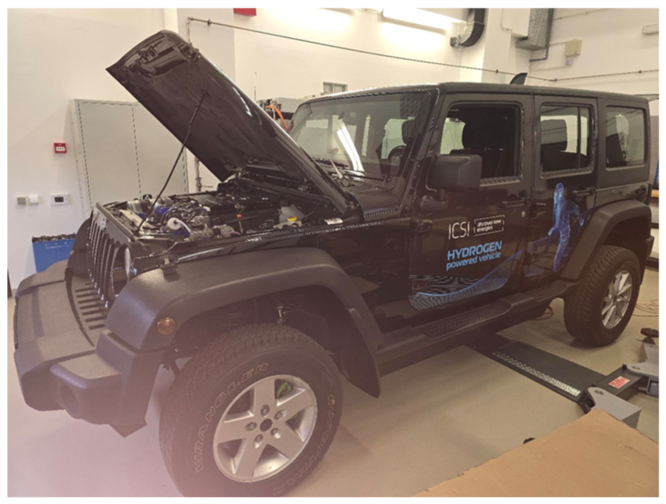
Figure 2.
CompactRIO controller integrated into the FCHEV powertrain (Jeep Wrangler-based).
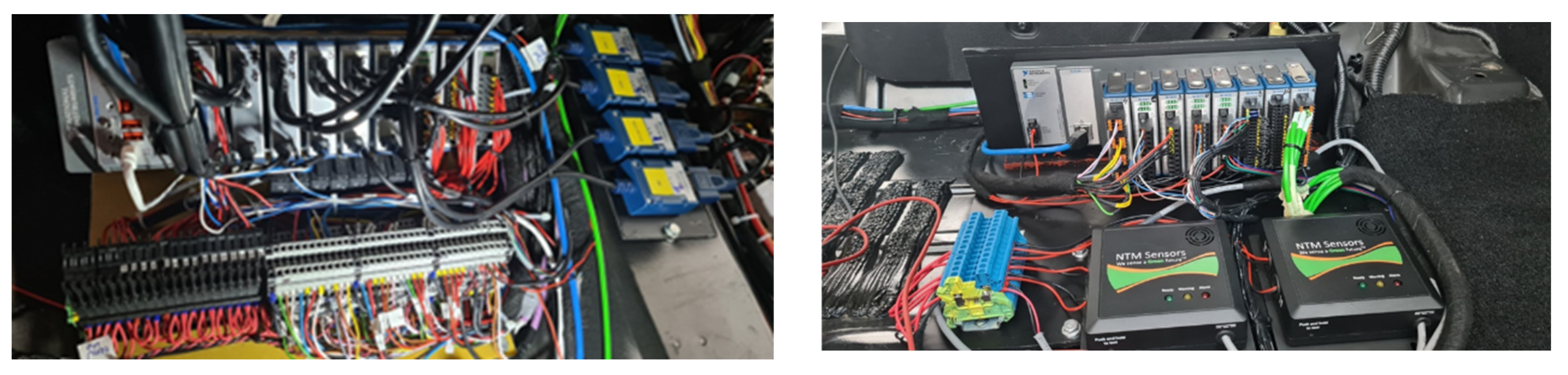
Figure 3.
EMS operating map.
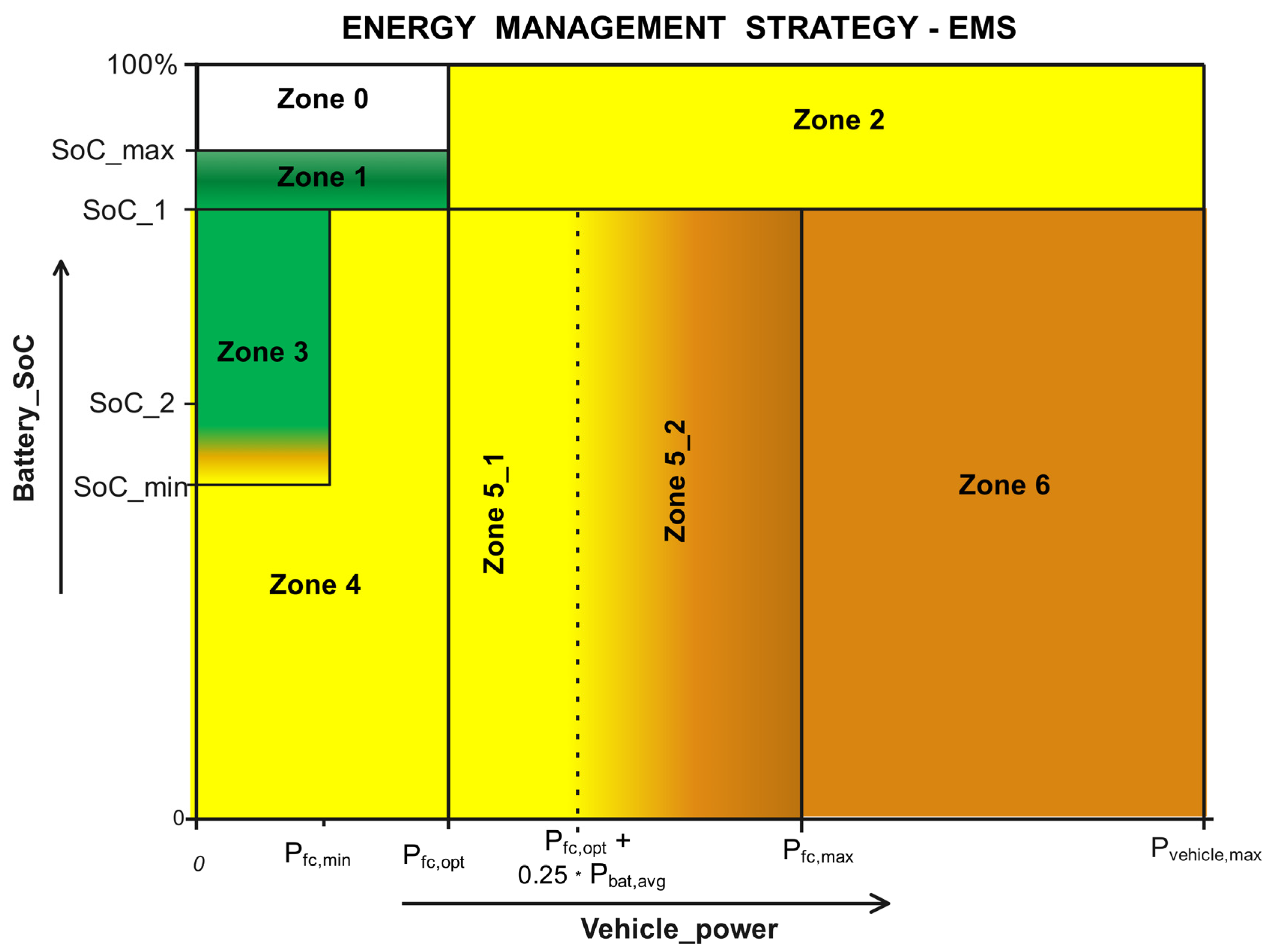
Figure 4.
Simulink model architecture used for the simulation of the Fuel Cell Hybrid Electric Vehicle (FCHEV).
Figure 4.
Simulink model architecture used for the simulation of the Fuel Cell Hybrid Electric Vehicle (FCHEV).
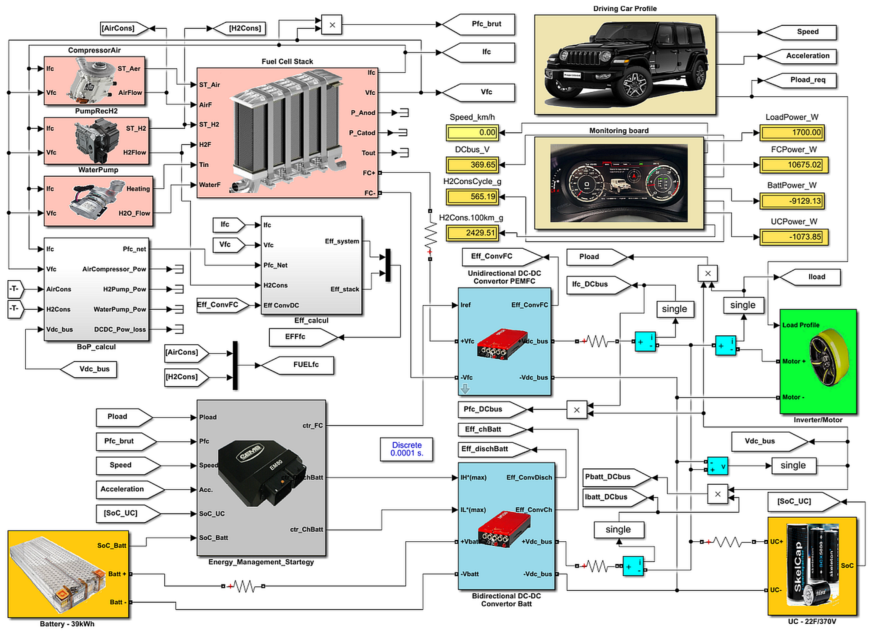
Figure 5.
Vehicle speed profile and power evolution during the WLTC Cycle 1.
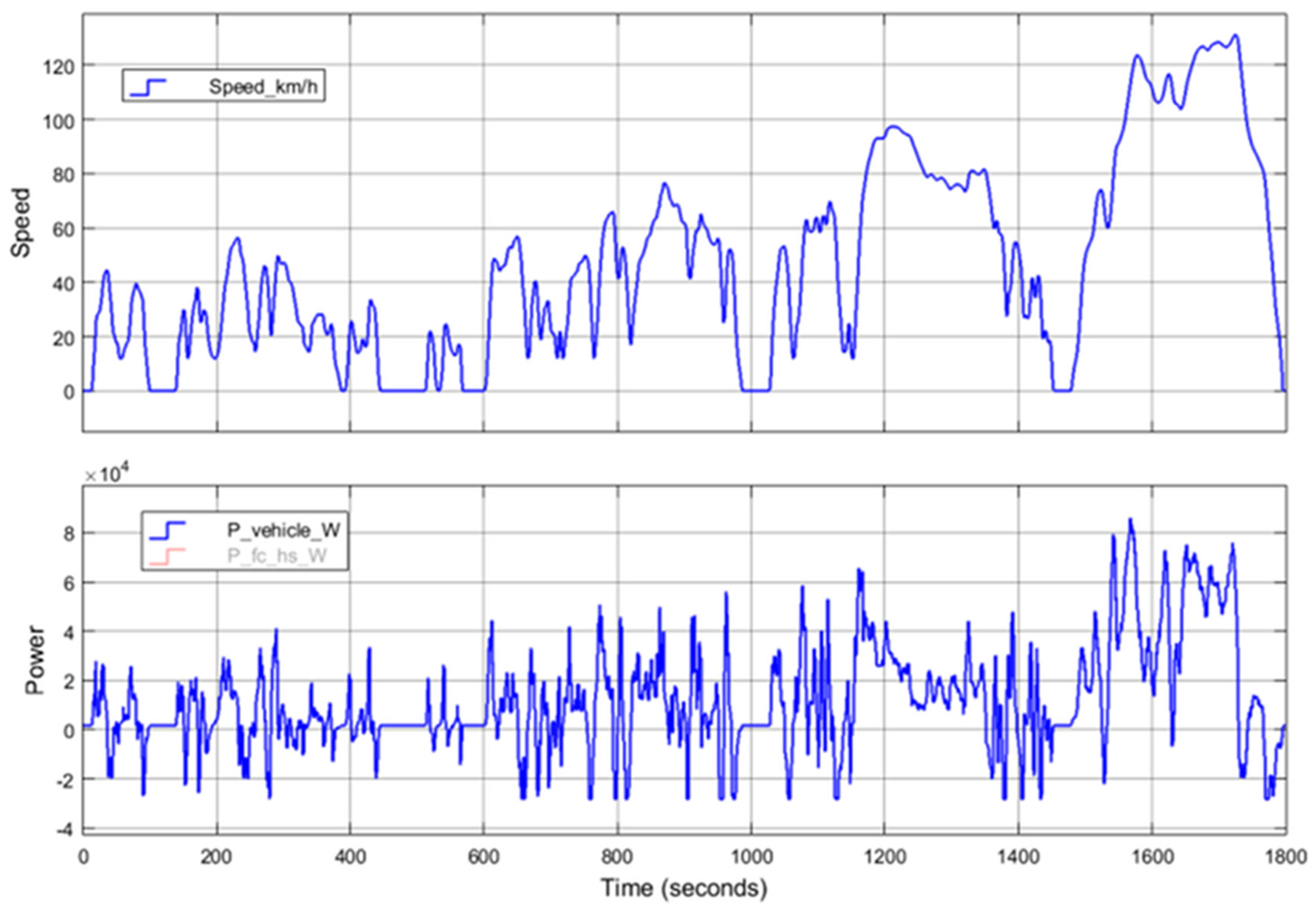
Figure 6.
HV-bus power profiles for WLTC Cycle 1: battery (P_batt_hs_W), ultracapacitor (P_uc_W), and fuel cell (P_fc_hs_W) contributions relative to vehicle power demand (P_vehicle_W).
Figure 6.
HV-bus power profiles for WLTC Cycle 1: battery (P_batt_hs_W), ultracapacitor (P_uc_W), and fuel cell (P_fc_hs_W) contributions relative to vehicle power demand (P_vehicle_W).
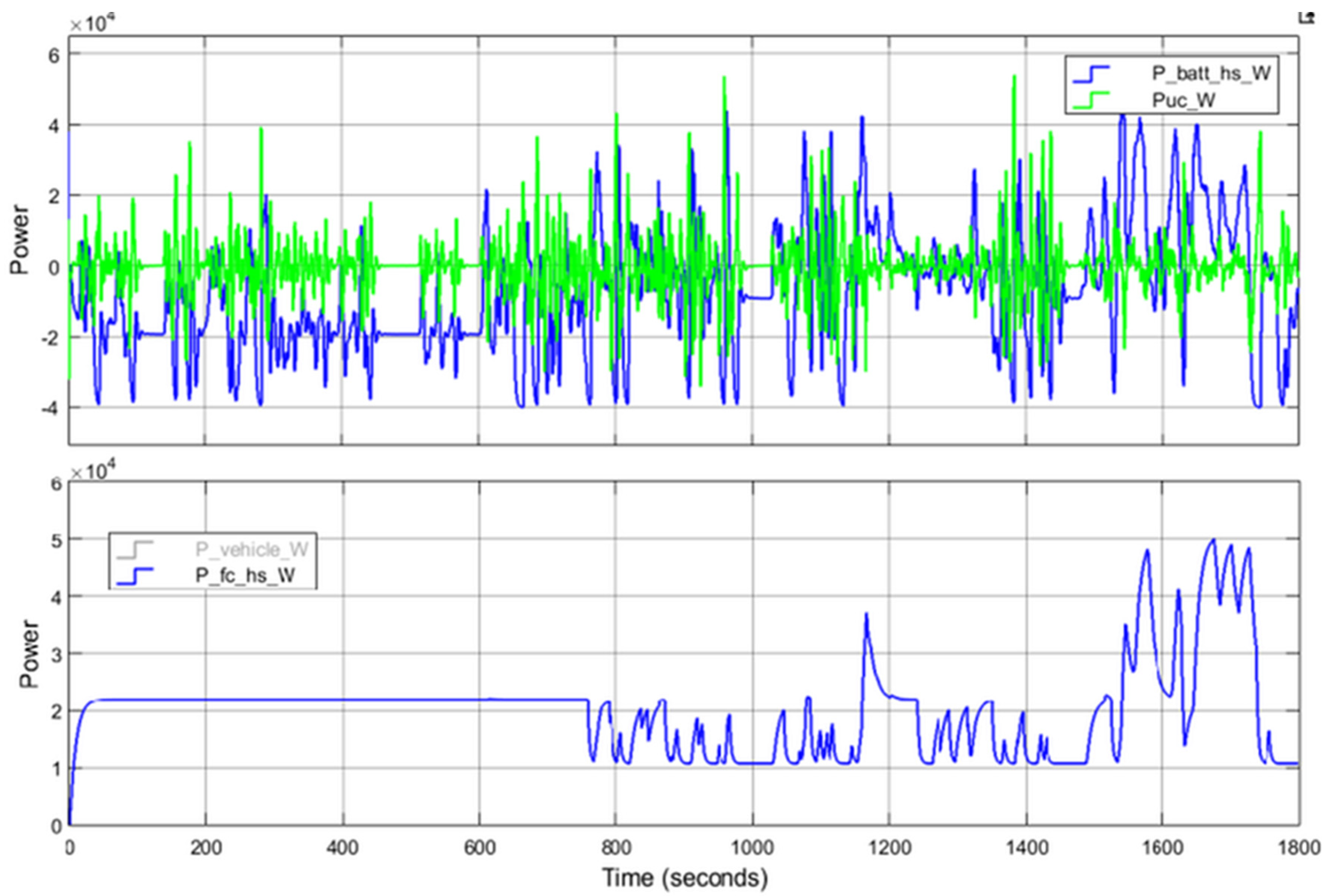
Figure 7.
Hydrogen consumption and battery state-of-charge evolution during WLTC Cycle 1.
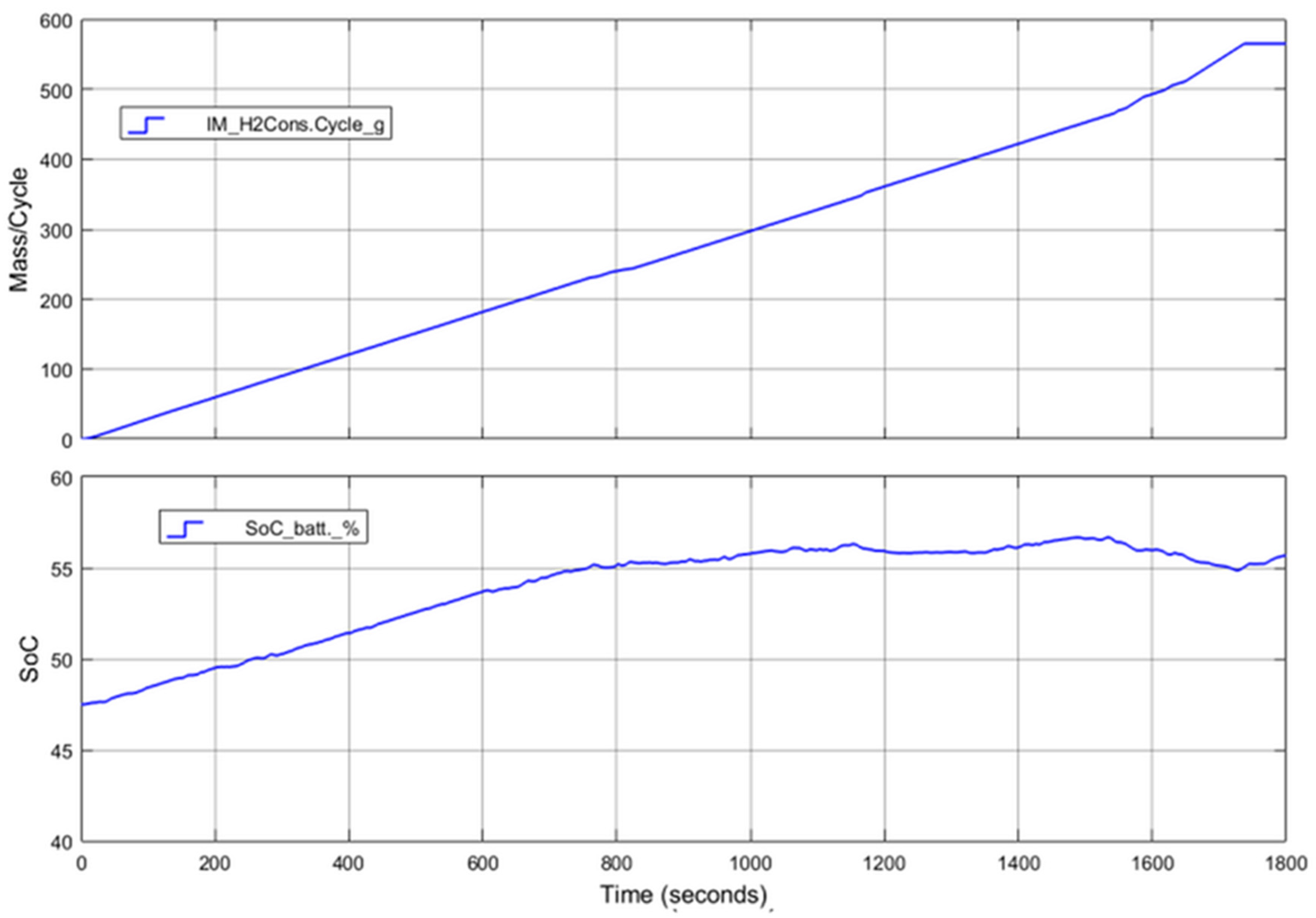
Figure 8.
Vehicle speed profile and cumulative distance.
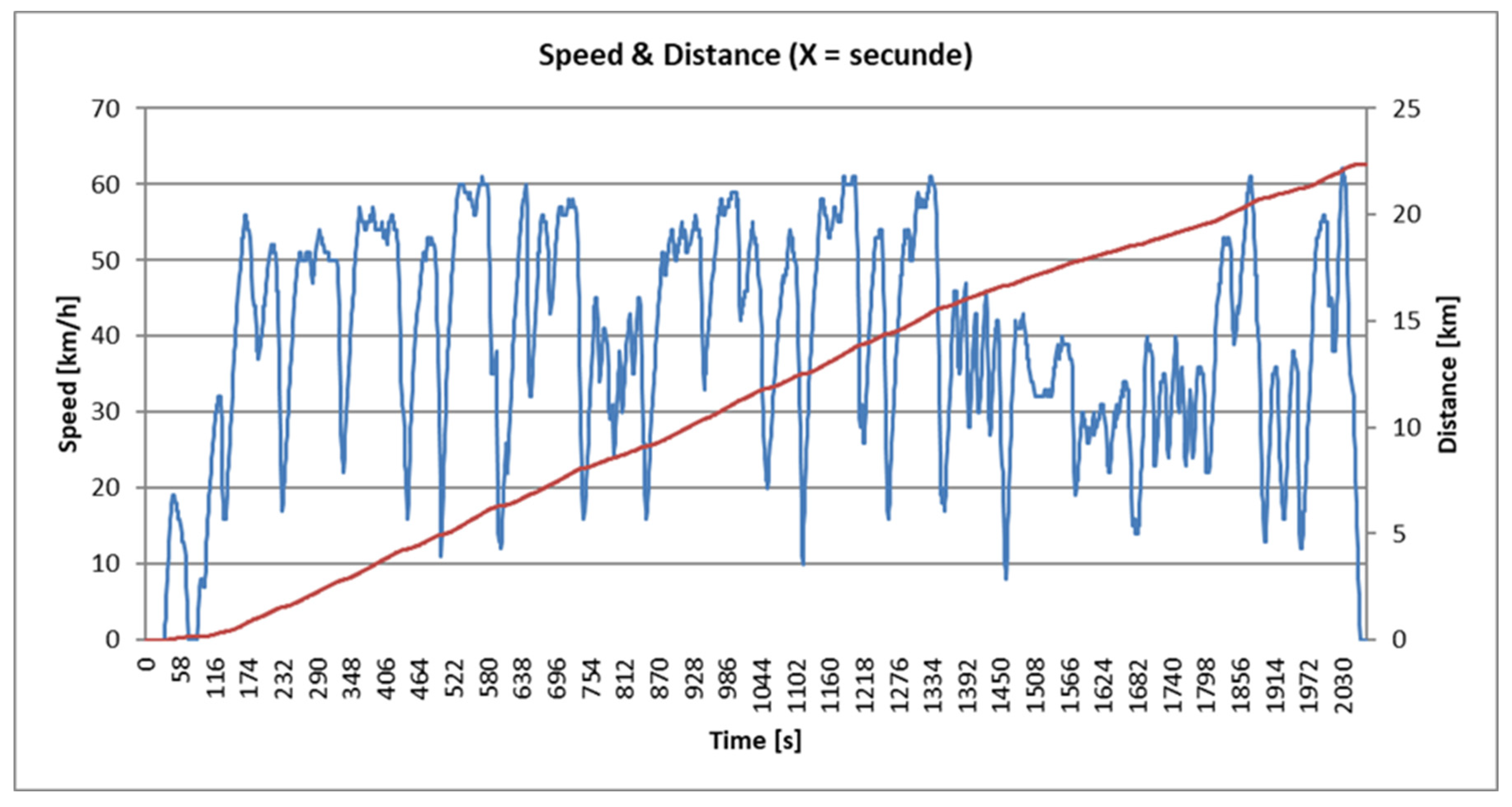
Figure 9.
Power split between fuel cell, battery, and traction load.
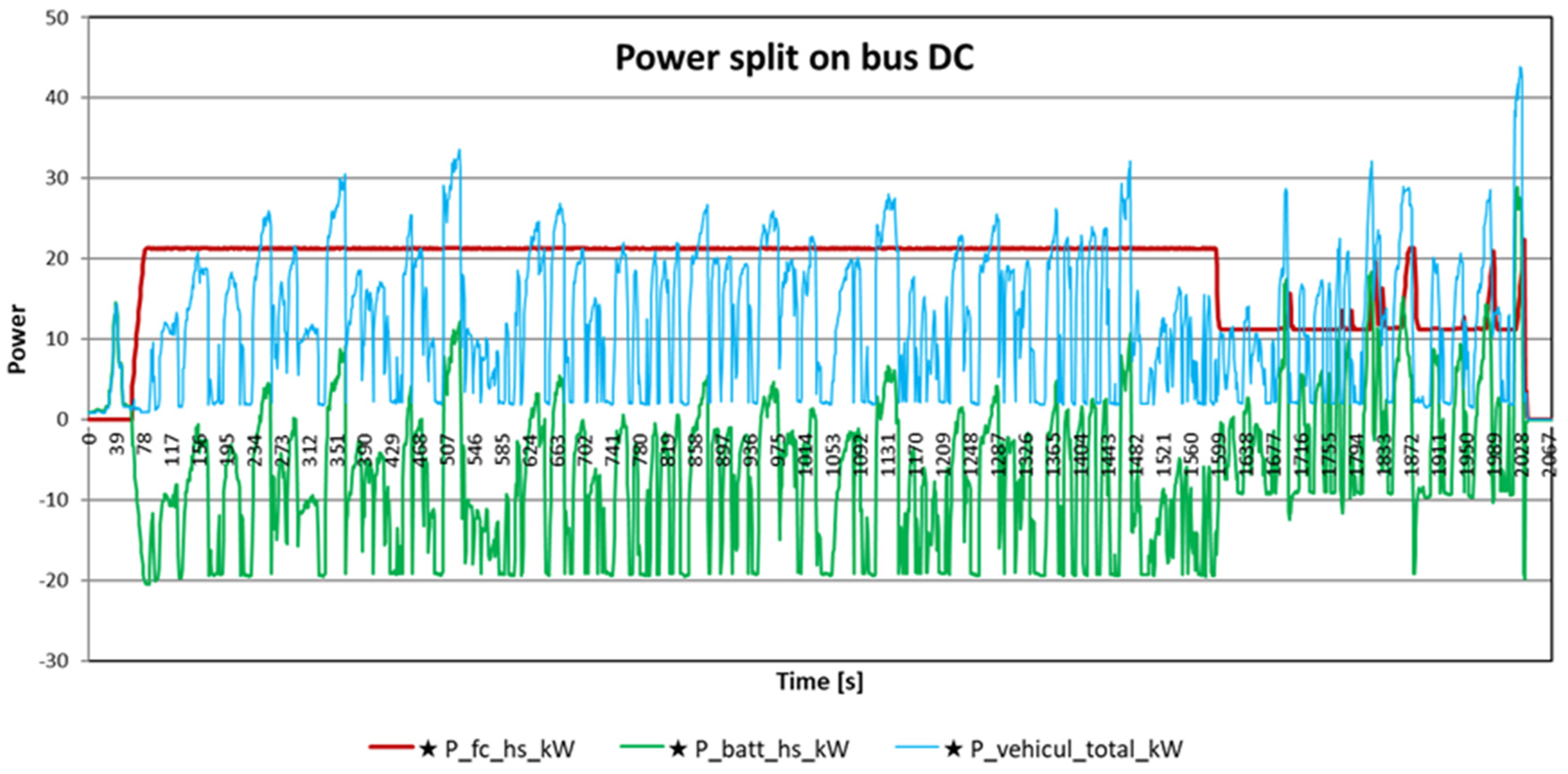
Figure 10.
Correlation between battery SoC and hydrogen flow.
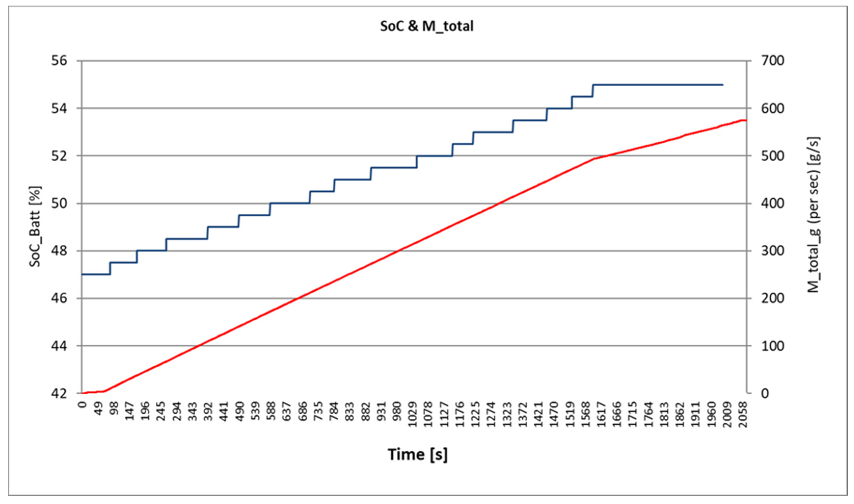
Figure 11.
Temporal distribution of the operating modes (Z0–Z6) recorded during the experimental test of the Wrangler FCHEV. The results show that the vehicle operated predominantly in Z3–Z5, corresponding to the high-efficiency zones of the fuel cell.
Figure 11.
Temporal distribution of the operating modes (Z0–Z6) recorded during the experimental test of the Wrangler FCHEV. The results show that the vehicle operated predominantly in Z3–Z5, corresponding to the high-efficiency zones of the fuel cell.
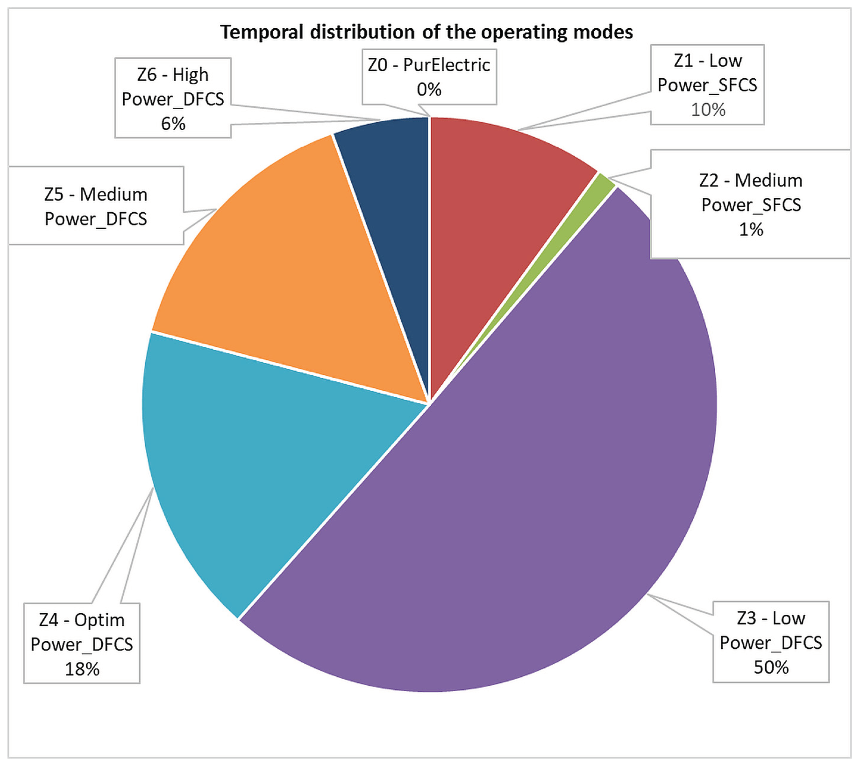

Table 1.
Summary of representative studies addressing EMS development for FCHEVs.
| No. | Objectives | Results | Advantages | Disadvantages |
|---|---|---|---|---|
| [4] | Review of sustainable powertrain architectures for FCHEVs | Overview of hybridization topologies and EMS trends | Broad comparison of EMS families | Lacks implementation details |
| [5] | Classification of EMS strategies for FC/HEV systems | Identified rule-based, optimization, and intelligent control classes | Good taxonomy and control structure overview | No experimental validation |
| [6] | Simulation of adaptive rule-based EMS for FCHEV | Reduced hydrogen consumption by 8% vs. baseline rule set | Real-time capable logic | Limited adaptability; no BoP coupling |
| [7] | Genetic algorithm (GA)-based EMS optimization | Achieved 10–12% efficiency improvement vs. rule-based | Automatic parameter tuning | High computational demand; offline optimization only |
| [8] | Dynamic programming (DP) benchmark for FCHEV | Global optimal reference results for fuel economy | Establishes EMS performance limits | Impractical for onboard execution |
| [9] | Model predictive control (MPC) for FC degradation minimization | 9% FC lifetime extension compared to rule-based | Integrates health management | Requires heavy computation and accurate prediction models |
| [10] | Adaptive ECMS for hybrid power distribution | Improved SoC tracking and H₂ efficiency under varying load | Good trade-off between optimality and simplicity | Sensitive to equivalence factor tuning |
| [11] | Reinforcement-learning (RL) EMS for FCHEV | Autonomous policy learning; improved hydrogen economy | Learns from data, adapts online | Requires large training datasets; poor interpretability |
| [12] | Neural network–based predictive EMS | Real-time power allocation with 3% hydrogen reduction | Fast and adaptive control | Needs continuous retraining; not vehicle-tested |
| [13] | Multi-objective EMS with durability and fuel economy targets | Balances degradation and efficiency objectives | Extends FC lifespan; efficient optimization | Complex cost function; calibration-dependent |
| [14] | Real-time EMS validation using CompactRIO controller | Demonstrated deterministic execution on embedded hardware | Fully real-time implementation | Simplified component modeling; no regeneration enabled |
| [15] | Dual-stack FCHEV EMS (simulation-based) | Explores stack load balancing and redundancy | Potential for power scalability | No experimental implementation or controller validation |
Table 2.
Comparative summary of recent EMS studies for FCHEVs (2023–2025).
| No. | Main Objective | Key Contributions | Identified Limitations |
|---|---|---|---|
| [25] | Adaptive rule-based EMS for FCHEV | Improved H₂ efficiency by 8%; simple calibration | No adaptability to unknown routes |
| [26] | GA-optimized RB EMS | 12% fuel saving; autonomous tuning | Offline optimization only |
| [27] | MPC for durability-aware EMS | 20% degradation reduction | High computational cost |
| [28] | Health-aware predictive control | Reduced aging effects; improved lifetime | Requires accurate degradation model |
| [29] | RL-based EMS | Learns policy; improves efficiency by 6% | Limited interpretability |
| [30] | Hybrid RL–ECMS controller | Dynamic equivalence factor adaptation | Tested only in simulation |
| [1] | Multi-physics FCS model validation | Validated model vs. Mirai CAN data (WLTC, US06) | High model complexity |
| [20] | Predictive ECMS with SoC planning | Integrated velocity prediction + NN SoC planner; 2–5% H₂ savings | Not validated on hardware |
| [31] | MPC with adaptive constraints (2024) | Health and temperature-aware control | High parameter sensitivity |
| [32] | Adaptive fuzzy ECMS (2025) | Self-tuning equivalence factor; 3% better H₂ use | Real-time instability at high load |
| [33,34] | Experimental EMS on CompactRIO | Deterministic embedded validation; dual-stack setup | Limited regenerative capability |
| [2] | Real-world calibration via CAN data | High-fidelity dynamic validation | Complex data preprocessing |
| [35] | Learning-based predictive EMS (2025) | Combines CNN and ECMS | Needs large dataset and GPU training |
Table 3.
Main technical specifications of the FCHEV demonstrator (Jeep Wrangler-based platform).
| Component | Specification |
|---|---|
| Vehicle mass | 2530 kg |
| Drag coefficient (Cd) | 0.58 |
| Frontal area (A) | 2.8 m² |
| Fuel cell stacks | 2 × PEM, 33 kW each |
| Battery pack | Li-ion, 170 V, 39 kWh |
| H₂ storage | 2 × 52 L Type IV @ 700 bar (~4.1 kg H₂) |
| Max traction power | 100 kW/150 kW peak-power (35 kW limited software for safety) |
Table 4.
Summary of EMS operating zones (Z0–Z6) defining the activation conditions, fuel-cell reference power levels, and functional objectives of the rule-based control strategy.
Table 4.
Summary of EMS operating zones (Z0–Z6) defining the activation conditions, fuel-cell reference power levels, and functional objectives of the rule-based control strategy.
| Zone | Active stacks | SoC range [%] | Vehicle Power Range [kW] | Fuel Cell Reference Power Pfc,ref [kW] | Description / Purpose |
|---|---|---|---|---|---|
| Z0 Pure Electric |
0 | > 85 | < 24.1 (P_fc,opt) | 0 | Battery and UC supply traction. FC off for high SoC / low load. |
| Z1 Low Power_SFCS |
1 | ≥ 80 | > 24.1 | 12.05 | One stack active; moderate load, SoC high; battery assists. |
| Z2 Medium Power_SFCS |
1 | 75 – 80 | > 24.1 to ≈ 28 | 24.1 | Single stack at optimal point; transients handled by battery/UC. |
| Z3 Low Power_DFCS |
2 | 55 – 75 | ≤ 24.1 | 24.1 (total ≈ 12 per stack) |
Dual stack recharges battery under low load; steady SoC control. |
| Z4A Optim Power_DFCS (Deep Recharge) |
2 | < 50 | < 24.1 | 24.1 | Both stacks at optimal power to recharge battery during low load. |
| Z4B Optim Power_DFCS (Nominal SoC) |
2 | 50 – 80 | 12.65 – 24.1 | 24.1 | Dual stack kept at efficiency optimum; surplus charges battery. |
| Z5_1 Medium Power_DFCS (Constant) |
2 | 55 – 80 | > 24.1 to ≈ 40 | 24.1 | DFCS held at optimum; battery covers excess load. |
| Z5_2 Medium Power_DFCS (Load-following) |
2 | 55 – 80 | > 35 – 55 | Only zone where FC tracks vehicle load; battery contributes ≈ 17 kW. | |
| Z6 High Power_DFCS |
2 | < 80 | > 35 | Both stacks at high output for traction and battery recharge; transients via UC. |
Table 5.
Cumulative energy flows, hydrogen consumption, and battery SoC evolution over eight WLTC cycles under EMS control.
Table 5.
Cumulative energy flows, hydrogen consumption, and battery SoC evolution over eight WLTC cycles under EMS control.
| Parameter | Cycle 1 | Cycle 2 | Cycle 3 | Cycle 4 | Cycle 5 | Cycle 6 | Cycle 7 | Cycle 8 | Total (8 cycles) |
|---|---|---|---|---|---|---|---|---|---|
| FC energy to bus [kWh] | 10.63 | 8.53 | 8.53 | 8.53 | 8.53 | 8.53 | 6.99 | 6.61 | 66.90 |
| Battery discharge [kWh] | 1.80 | 1.95 | 1.95 | 1.95 | 1.95 | 1.95 | 2.60 | 2.74 | 16.87 |
| Battery charge (regen) [kWh] | 6.43 | 4.48 | 4.48 | 4.48 | 4.48 | 4.48 | 3.59 | 3.35 | 35.79 |
| UC discharge [kWh] | 1.11 | 0.00 | 1.00 | 1.00 | 1.00 | 1.00 | 0.96 | 0.95 | 7.03 |
| UC charge (regen) [kWh] | 1.05 | 0.00 | 0.95 | 0.94 | 0.94 | 0.94 | 0.90 | 0.89 | 6.61 |
| Hydrogen consumption [kg] | 0.565 | 0.440 | 0.441 | 0.441 | 0.441 | 0.441 | 0.362 | 0.338 | 3.469 |
| Battery SoC initial [%] | 47.5 | 55.7 | 61.8 | 65.9 | 70.0 | 74.1 | 78.15 | 78.9 | – |
| Battery SoC final [%] | 55.7 | 61.8 | 65.9 | 70.0 | 74.1 | 78.15 | 78.9 | 78.92 | – |
Table 6.
Comparative performance of EMS strategies reported in the literature. Summary of hydrogen consumption and efficiency for FCHEV systems under WLTC conditions.
Table 6.
Comparative performance of EMS strategies reported in the literature. Summary of hydrogen consumption and efficiency for FCHEV systems under WLTC conditions.
| Reference | EMS type | Vehicle type/cycle | H₂ consumption [kg/100 km] | Normalised H₂ consumption [kg/100 km·m²] | Efficiency [%] | Remarks |
|---|---|---|---|---|---|---|
| [42] | Rule-based EMS | Sedan FCHEV / WLTC | 0.78–0.85 | 1.12 | 50–55 | Constant-P FC zones |
| [43] | Optimised EMS | SUV FCHEV / WLTC | 0.80 | 1.15 | 53 | Load-balanced dual-source |
| [41,44] | Fuzzy EMS | Mid-size FCHEV / NEDC | 0.82 | 1.20 | 54 | Single FC stack |
| [5] | Rule-based | Compact FCHEV / WLTC | 0.90–1.00 | 1.40 | 48 | No load-following |
| [40] | Adaptive control | SUV FCHEV / WLTC | 0.75–0.80 | 1.10 | 52 | Dynamic thresholding |
| This work | Rule-based (dual FC, hybrid) | Wrangler FCHEV demonstrator / 8×WLTC | 1.35 (sim.) / 1.67 (exp.) | 1.03 (normalised) | 52–58 | Dual-stack, load-following Z5₂ |
Table 7.
Experimental Energy and Hydrogen Summary (Wrangler FCHEV).
| # | Metric | Value |
|---|---|---|
| 1 | Total test duration [s] | 2074 |
| 2 | Total distance [km] | 22.37 |
| 3 | Total hydrogen mass [kg] | 0.574 |
| 4 | Hydrogen consumption [kg/100 km] | 2.567 |
| 5 | Normalised hydrogen consumption [kg/100 km·m²] (per Cd·A = 1.624) | 1.581 |
| 6 | Fuel cell DC output energy (∑PFC·dt) [kWh] | 13.1 |
| 7 | Battery net energy (∑Pbatt·dt) [kWh] (+: discharge, −: charge) | −0.9 |
| 8 | Traction/load energy (∑Pload·dt) [kWh] | 12.3 |
| 9 | Hydrogen chemical energy (LHV·mass) [kWh] | 19.13 |
| 10 | Average fuel cell DC efficiency (DC_out / H₂_in) [–] | 0.684 |
Disclaimer/Publisher’s Note: The statements, opinions and data contained in all publications are solely those of the individual author(s) and contributor(s) and not of MDPI and/or the editor(s). MDPI and/or the editor(s) disclaim responsibility for any injury to people or property resulting from any ideas, methods, instructions or products referred to in the content. |
© 2025 by the authors. Licensee MDPI, Basel, Switzerland. This article is an open access article distributed under the terms and conditions of the Creative Commons Attribution (CC BY) license (http://creativecommons.org/licenses/by/4.0/).
Copyright: This open access article is published under a Creative Commons CC BY 4.0 license, which permit the free download, distribution, and reuse, provided that the author and preprint are cited in any reuse.


