Submitted:
19 January 2026
Posted:
20 January 2026
You are already at the latest version
Abstract
With the rapid advancement of IoT devices, there is an increasing demand for MPU environments that are low in overall system resources while achieving low power consumption, high energy efficiency, and high performance.Such systems must be capable of controlling multiple sensors and wireless communication modules on minimal battery power, while retaining several days to weeks of logs even under unstable wireless conditions.In logging applications, sensor data are continuously generated and written to non-volatile memory.However, conventional file systems are not designed to handle these operations efficiently. This is because attempting to simultaneously achieve low power consumption, high performance, and power-failure resilience introduces significant overhead and complexity, ultimately degrading energy efficiency.In short, traditional file systems inherently face trade-offs between power efficiency, power-failure resilience functionality, and performance. In typical designs, achieving low power consumption, high performance, and power-failure resilience without relying on specialized modules or custom hardware components requires more resources—such as CPU cycles, power, circuit size, and component count—leading to increased complexity.Therefore, realizing these properties using only general-purpose resources remains a challenging task.Compact/logging type: The proposed time-locality-optimized, hardware-cooperative log-structured file system achieves low power consumption, high performance, and resilience to unexpected power loss using only common components and interfaces, without special or custom hardware.This study reconsiders the boundary design between file system control and hardware-cooperative control in a bare-metal environment without an operating system, and presents a deterministic storage control model based on temporal locality.
Keywords:
embedded systems
; IoT devices
; log-structured file system
; hardware-assisted optimization
1. Introduction
IoT devices are a category of embedded systems. In embedded system design, the choice of operating system (OS) is a critical consideration. Recently, from a security standpoint, adopting (Embedded) Linux has become the de facto standard—for example, enabling compliance verification through Software Bill of Materials (SBOM)–based security clearance.
However, under strict resource constraints, an approach that does not rely on an operating system can also be a practical and efficient solution. The module block configuration of the proposed system is shown in Figure 1.
1.1. Practical Operation Background
The file system proposed in this study has been embedded in equipment operating under strict power and computational resource constraints, and was field-tested in training equipment for racing competitions. The equipment requires long-term retention of sensor logs and rapid recovery from unexpected power loss.
Furthermore, the equipment is designed for battery-driven operation, capable of supplying instantaneous currents up to approximately 1 A at around 3.6 V, while average power consumption reduction is critical for long-term operation. The target board boosts 3.6 V to 5 V and supplies power to the RP2040’s VSYS. In this study, to continue logging under such power constraints, we adopted a design that confines append processing to the low-power processing system and separates GC/metadata adjustment to a relatively high-performance processing system.
This study aims to organize the design decisions required under these operational requirements (including the separation of responsibilities between append processing and GC/metadata adjustment) from a system software perspective and present them as design principles.
1.2. Bare-Metal Systems
For example, the pico-sdk for Raspberry Pi Pico is not an operating system, but provides a software development kit (SDK) that includes a ported LWIP (TCP/IP, UDP/IP protocols), hardware FIFO access, memory mapping, linker scripts, and device drivers for standard peripherals of the Pico W board.
However, it does not include a ported journaling file system such as ext4, nor embedded FAT-based file systems with mechanisms for resilience to unexpected power loss. Consequently, while it enables lightweight connectivity and control, it lacks robustness in non-volatile storage management.
1.3. Embedded Linux
By contrast, adopting Linux offers significant advantages, such as access to a stable, feature-rich, and versatile file system, a mature and reliable network protocol stack, and stable device drivers. These attributes make Linux the de facto standard for many embedded applications. Nevertheless, in scenarios where constraints and requirements—such as power consumption, limited memory space, the number of attached sensors, and network communication frequency—cannot tolerate the overhead of a full OS, a bare-metal approach becomes more effective.
This is particularly true when porting a file system to a target OS cannot satisfy performance or resource limitations inherent to the system design.
In this use case, the system must operate directly on hardware interfaces such as SPI- or NAND-based non-volatile memory, while satisfying requirements for data reliability, low power consumption, and tolerance to unexpected power loss.
2. Functional Requirements
2.1. Control of Multiple Sensors
The system is compactly designed to control multiple sensors while maintaining wireless communication capabilities. In scenarios where wireless connectivity is unstable or unavailable, the device must be capable of temporarily storing acquired sensor data in NAND flash non-volatile memory areas. Subsequently, when wireless conditions recover—or when the device switches to a wired connection such as USB—the accumulated data can be transferred.
2.2. Resilience to Unexpected Power Loss
The system must incorporate a file system with strong resilience to unexpected power loss, particularly in low-power, battery-driven environments. Such power-loss resilience is essential to prevent data corruption and ensure continuous data logging and recovery without the need for specialized hardware components.
2.3. Focus of This Study
This paper reports on the design and evaluation of the Data-Access / Temporal-Locality-Optimized / Hardware-Coordinated File System for logging-type IoT devices. The proposed system addresses the above functional requirements by combining efficient data access, time-locality optimization, and hardware-level coordination, providing both robustness and performance under strict resource constraints.

Table 1.
Comparison of Existing File Systems.
| File System |
Unexpec- ted Power Loss |
Mount/ Boot |
Wear Leveling |
Resource Size/ Footprint |
|---|---|---|---|---|
|
FAT (12,16,32,v) |
— | ◯/— | — | ◯/— |
| LogFS | ◯/— conditional |
— | ◯ | — |
|
This Paper MXFS |
◯ | ◯ | ◯ | ◯ |
2.3.1. Notes
- “◯” indicates that the property is explicitly addressed in design for the requirements targeted by this study.
- “—” indicates that the requirement is not a primary design goal, or generally does not satisfy the requirement.
- “◯/—” indicates conditional or partial support (e.g., LogFS may provide power-loss resilience under certain conditions but not universally).
- FAT-based systems (including TFAT) require operation that assumes no power loss (synchronous design, etc.), and are treated as not having power-loss resilience for this study’s requirements.
- “Unexpected Power Loss” in this table refers to resilience that holds structurally at the file system level, independent of external power design or operational (synchronous call) dependencies.
3. Existing Lightweight File Systems
3.1. littlefs
The existing embedded file system littlefs1 provides power-loss resilience on SPI Flash, but its design assumes block device abstraction and general-purpose file system semantics. In contrast, MXFS proposed in this study treats SPI Flash directly as physical log storage along the time axis, adopting an append-only model that does not require overwrites or rollbacks. With this design, power loss can be treated as an event where “the last log entry is interrupted in an incomplete state,” and recovery is possible by entry boundary detection (length information + commit marker) through skip/recovery. For wear-leveling, the basic structure cyclically uses the entire area through appending, and the state of each erase block and page is self-contained as described by valid/invalid bits held in their own headers. Therefore, the log structure does not assume write concentration to specific areas, resulting in mitigation of uneven usage per erase block. As described above, littlefs and MXFS differ in design premises and target usage environments, and this study adopts a design specialized for resource-constrained, power-loss-prone environments like the latter.
3.2. SPIFFS
SPIFFS2 is widely used as a lightweight file system for SPI NOR Flash, but its design focus is on operation under constraints such as minimum RAM usage, which differs from the premise of “data placement/recovery model that treats time axis (time locality) as a primary concept” emphasized in this study. Also, ESP-IDF documentation indicates that SPIFFS may be corrupted by power loss during file system operations, and recovery depends on the check mechanism esp_spiffs_check. Therefore, SPIFFS does not treat temporal consistency under power-loss-prone environments (determining recovery points consistent with time locality) as a primary design goal, and focuses on a different problem domain than what MXFS aims for.
3.3. Log-Structured File Systems
Log-Structured File Systems (LFS) express updates as append logs, having trade-offs between power-loss resilience and mount delay. Existing implementations such as F2FS and NILFS2 operate via block device layers, requiring reintroduction of fsync(2) and similar mechanisms. This study presents a structural design that avoids this problem by realizing LFS design principles through a direct append method.
4. Requirements and Characteristics
The target system is designed to operate in an environment with stringent power and resource constraints, while maintaining high performance and reliability. The key requirements and characteristics are as follows:
- High data access performance: Achieve fast read and write access for real-time or near-real-time processing of sensor information.
- Strong resilience to unexpected power loss: Maintain data integrity even in the event of sudden power interruptions.
- Small footprint and low power consumption: Both hardware and software components should be optimized for compactness and minimal energy usage.
- Multi-sensor control capability: Efficiently manage and synchronize multiple sensor inputs.
- Wireless communication support: Support integrated wireless connectivity for data transmission and remote monitoring.
- Over-the-Air (OTA) updates: Support secure OTA firmware updates; this topic is beyond the scope of this paper.
- Use of SPI/NAND flash memory: SPI/NAND flash is advantageous due to its stable supply chain, ease of integration, large capacity, and broad compatibility and availability.
- Temporal data locality: Provide access to sensor data stored in non-volatile memory for the past few days, ensuring temporal locality of reference.
- Graceful degradation on power loss: Loss of unsynchronized sensor data during unexpected power failure is acceptable.
- Low-power operation under poor connectivity: Continue data storage and deferred transmission even in environments with unstable or limited wireless connectivity.
5. Proposed Technique
The proposed technique mitigates these issues by introducing temporally distributed processing and employing coordinated software-hardware finite-state machine (FSM) control to manage SPI/NAND flash memory access permissions between two MPUs. The FSM circuit configuration is shown in Figure 2, the timing chart in Figure 3, the FSM coordination switch in Figure 4, and the protocol stack in Figure 5.
This coordinated approach effectively eliminates the mount-time problem observed in conventional log-structured file systems, providing an architecture suitable for resource-constrained environments.
5.1. FSM Circuit Configuration
The FSM circuit shown in Figure 2 consists of three modules: a high-speed domain controller (C1, Mother side), a low-speed domain controller (C2, Child side), and a Selector. The Child side can acquire bus ownership only in state , with the Mother side holding ownership by default.
5.2. Timing Chart and State Transitions
Figure 3 shows the signal transitions and state transitions during ownership switching between Mother/Child. This design structurally prevents undefined states and bus contention during transitions.
5.3. Physical Layer Switching Mechanism
Figure 4 shows the physical layer bus switching mechanism based on FSM control. The four signal lines of SPI/NAND flash memory (SCLK, MOSI, MISO, CS#) are connected to either the Mother side or Child side through an analog multiplexer.
The Moore machine output Q is directly connected to the multiplexer’s selection input, driving physical bus connection switching in synchronization with state transitions. This configuration guarantees the following characteristics:
- Electrical isolation: The non-selected MCU is completely disconnected from the SPI bus, preventing bus contention and shorts.
- Low power consumption: The SPI peripheral of the non-selected MCU can be disabled, minimizing leakage current.
- Deterministic switching: Output is finalized after Moore machine state transition completes, eliminating undefined behavior in intermediate states.
5.4. Testbench Verification
The proposed FSM was logic-simulated in a Verilog HDL testbench environment, and timing validity was confirmed in the normal operation model3. Functionally equivalent behavior was also confirmed in the GPIO-based prototype implementation.
6. Append Only Write (AOW)
In the proposed system, the flash write timing for user payloads to the non-volatile storage area is determined by the data size after differential compression, with writes performed in page-sized increments of 2,048 bytes. Sensor data that becomes incomplete due to unexpected power failures or other interruptions is simply skipped during subsequent read operations. Therefore, equivalents to msync(2) and fsync(2) are not required in this design and are not implemented. By guaranteeing consistency at the physical page level through AOW, application-level fsync(2) becomes unnecessary.
7. Fast Mount
After an unexpected power loss in typical IoT devices, the system must be capable of rapid restart and prompt resumption of data streams, with minimal downtime and data continuity. The mechanism to minimize target block/page scanning = mounting process; DMA overhead is shown in Figure 6.
Figure 7: When the first controller operates at the first clock frequency (e.g., 125 MHz) and the second controller operates at a second clock frequency higher than the first (e.g., 200 MHz), we measured that the first controller achieves fast mount in 6ms. The wear-leveling mechanism in the proposed system, essential for long-lifetime architecture, is shown in Figure 8.
Delta compression design is also essential for long-lifetime architecture. The layer/differential architecture is shown in Figure 9.
8. Unexpected Power Loss
In common open-source file systems (FATxx, ext4, log-structured variants, etc.), journaling (as in ext4) and log-structured architectures are established approaches for improving resilience against unexpected power loss. However, neither of these solutions is well-suited for low-resource MPUs. Selecting ext4 often results in resource exhaustion, while adopting a log-structured file system incurs significant mount-time overhead. Several commercial or open implementations for RTOS environments claim to provide resilience against unexpected power failures. However, most of these systems are essentially derivatives of journaling file systems, typically employing techniques such as compressed transaction logs or distributed writes across multiple blocks or pages. None of these designs are fundamentally robust against unexpected power loss.
The only file system currently suitable for small-footprint IoT devices that offers both compactness and power-failure resistance is Reliance Edge (Tuxera Reliance Edge Tiny Power-Failsafe File System). However, it was deemed economically impractical for this system due to the time and cost overhead associated with its licensing process. The resilience design against unexpected power loss is shown in Figure 10.
8.1. LFS via Block Devices and Power-Failure Resilience Issues
Originally, log-structured file systems (LFS) treat all updates as append-only logs, requiring no transactions or journals to maintain consistency, and are structurally robust against unexpected power failures. However, implementations widely used in embedded Linux environments, such as F2FS and NILFS2, operate through the Linux kernel’s page cache and block device driver layers. This structure causes the LFS’s inherent temporal log consistency to depend on the device-side Flash Translation Layer (FTL) cache and OS buffering, leaving the possibility that unsynchronized data or meta-information immediately before power failure may be lost. As a result, these systems must reintroduce fsync(2) and transaction resynchronization processing that was originally unnecessary in LFS, effectively losing the structural power-failure resilience advantage that LFS possesses. The proposed MXFS eliminates this problem fundamentally by removing the block abstraction layer and adopting a direct append method that minimizes memory caching, maintaining a consistent log structure even after power failure.
9. Interfaces
Table 2.
POSIX Interfaces.
| Interface | Description |
|---|---|
| open | Generate or open a file. |
| close | Close a file. |
| read | Read data from a file descriptor into a buffer. |
| write | Write data from a buffer to a file descriptor. |
| create/release | Initialize or release the file system, including mount, unmount, and boot processes. |
Table 3.
This Paper’s Interfaces.
| Interface | Description |
|---|---|
| append | Append data to a specific layer (flush is automatic). |
| create/release instance |
Initialize/Release file system, mount/unmount, including boot. |
Processes related to file names and path resolution associated with file descriptors are excluded to eliminate unnecessary overhead. Timestamps are compressed and stored within the payload header using an initial value and incremental step method, reducing metadata size and access latency.
10. DMA Performance
As the measurement results indicate, the memory access performance in both NAND flash read and write operations is proportional to the DMA transfer size.
Figure 11.
DMA, API Performance.
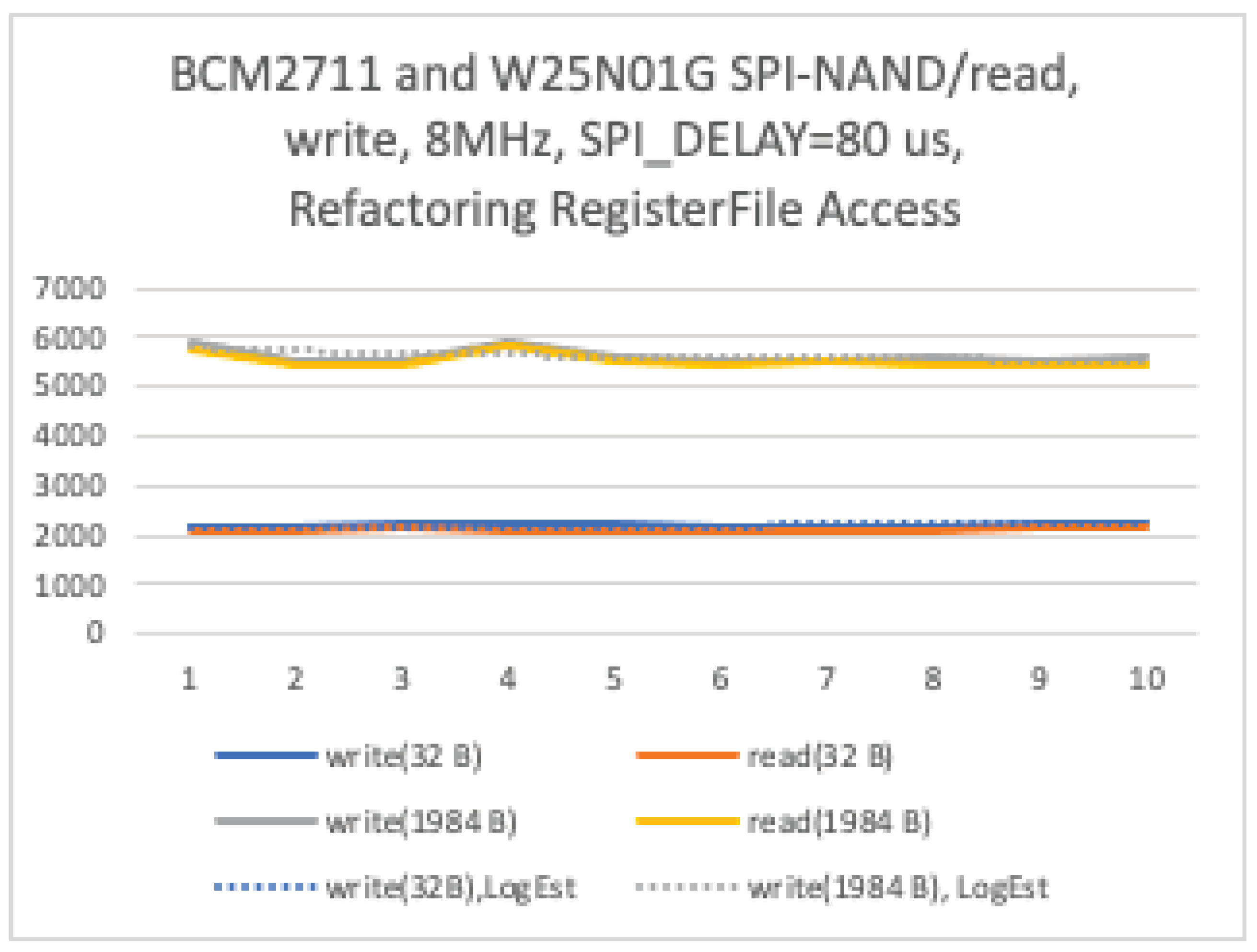
DMA and API performance directly affect scan time during mount and write latency during append. For example, with a page size of 2048B, read speed of approximately 5.5MB/s provides the lower bound for target block scan time (approximately N_page × 0.37ms) in the fast mount shown in Figure 6. This represents the fundamental performance limit indicator for this file system.
11. E2E Power Consumption
In this implementation, due to the physical configuration of RP2040 and CYW43, transitioning the wireless module to DeepSleep requires DeepSleep of the entire SoC. Therefore, power consumption during normal operation is dominated by CYW43, and the power difference due to MXFS I/O processing becomes secondary at the system level.
Figure 12.
Functional Blocks, Software Stack.
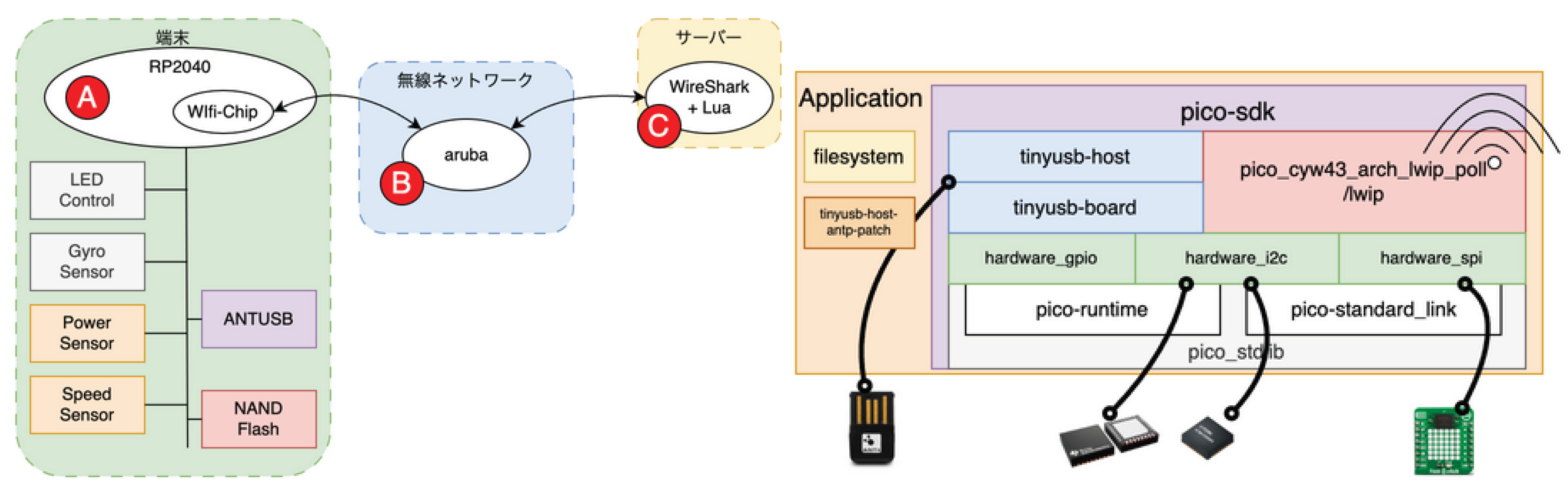
The evaluation was conducted in the same environment as the implementation configuration shown in Figure 19. We measured the power line current of the entire system during wireless operation of the RP2040 (excluding BCM2711) simultaneously with RSSI at each measurement point.
As distance from the Wi-Fi access point increased, the Received Signal Strength Indicator (RSSI) at the IoT terminal decreased. In indoor environments with few obstructions, the reflection and diffraction effects of radio waves caused non-uniform spatial distribution of reception power, and it was confirmed that dead zones tend to occur at specific distances where reception sensitivity drops.
Figure 15.
Wireless Signal Strength by Area.
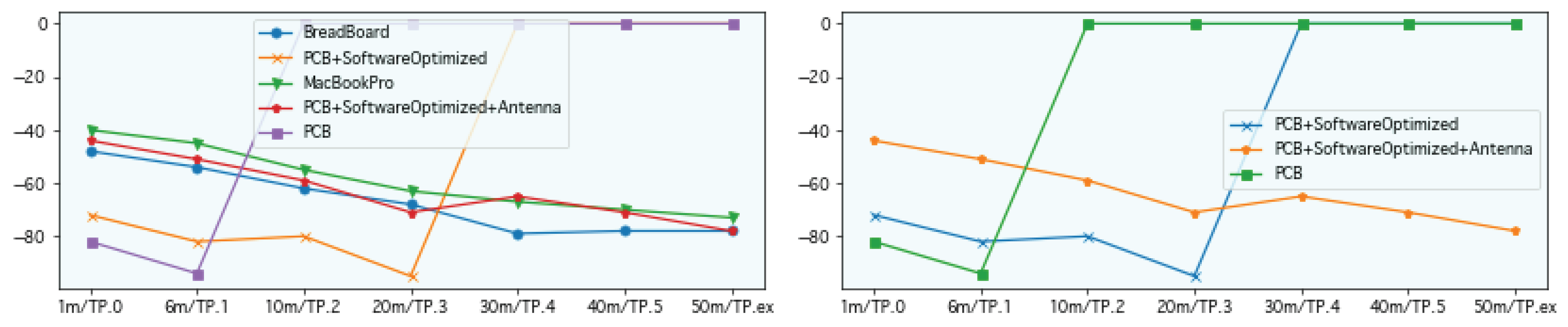
A correlation was observed between RSSI variation observed at the terminal and overall system power consumption, suggesting that power consumption variation is primarily attributable to the transmission/reception operation of the wireless communication module.
From the above, in this system, current fluctuations associated with wireless module transmission/reception processing and accompanying FSM processing dominate overall system power consumption. This result indicates that power efficiency in low-resource log-structured file systems like MXFS should be considered as “system coordination design” including power domain and processing responsibility separation, rather than algorithm-level optimization such as append processing or GC.
In this PoC, we did not adopt the RP2040’s DeepSleep function (Figure 16). Details are described as future work later.
12. Related Works
12.1. Penalties in Block Interfaces
Typical flash-based SSDs are provided as block devices, and non-sequential writes trigger garbage collection (GC) inside the Flash Translation Layer (FTL), causing serious Write Amplification (WA). This WA is known to cause performance degradation and latency instability. In A Zoned Storage Optimized Flash Cache on ZNS SSDs, [1] proposes a cache mechanism using Zoned Namespace SSD (ZNS SSD) to eliminate such semantic gaps in block interfaces. ZNS SSDs allow only sequential writes to each zone and erase all data at once through zone reset. Compared to conventional SSDs, this achieves higher write performance and lower cost per GiB due to reduced OP (Over-Provisioning) for internal GC, addressing performance and durability issues in flash caches. MXFS proposed in this study shares commonalities with this zone-based storage design philosophy, while having originality in systematizing file system design for general-purpose SPI/NAND flash not limited to ZNS SSDs, targeting resource-constrained environments. This work has been filed as Japanese Patent Application No. 2025-186101.
12.2. Log-Structured File System Basics
The concept of a Log-Structured File System (LFS) was originally proposed by Rosenblum and Ousterhout in their seminal work, The Design and Implementation of a Log-Structured File System [2]. LFS was designed to address the widening imbalance between CPU speed and disk seek latency by treating the entire storage device as a sequential log. All modifications—file data, metadata, and directory updates—are appended sequentially to the log, thereby minimizing random seeks and improving overall write throughput.
The original LFS architecture, as implemented in Sprite LFS, introduced three key mechanisms: (1) segmentation of the log into fixed-size segments, (2) a segment cleaner that compacts live data to maintain large contiguous free areas, and (3) checkpointing combined with roll-forward recovery to restore a consistent state after a crash. This design demonstrated that LFS could utilize up to 70% of the raw disk bandwidth for writes—an order of magnitude higher than traditional Unix FFS—while achieving efficient recovery and high throughput for small-file workloads.
However, the recovery model in Sprite LFS assumes a continuously powered, resource-rich environment, such as workstation-class systems with sufficient CPU and memory resources and stable disk I/O. In contrast, applying the same LFS model directly to embedded or IoT systems is impractical due to (a) limited CPU frequency, (b) constrained RAM, (c) the use of SPI- or NAND-based flash memory with high access latency, and (d) frequent power interruptions. In such power-volatile environments, metadata updates must be deferred until the system enters a stable state, while sensor payloads and other data may still be appended to the log without guaranteeing immediate consistency. Recovery is therefore context-dependent: it occurs only when the system transitions to a stable power domain or is temporarily coupled to a higher-performance controller capable of checkpointing and log reconciliation.
In our implementation, this transition is supported by a hardware design that enables shared and switchable SPI-based access to the origin memory source, allowing a high-performance processor to participate in recovery only when stable power and sufficient computational resources are available.
12.2.1. Disconnection of Philosophy in LFS via Block Devices
Recently, in embedded Linux environments, log-structured file systems (LFS) such as F2FS and NILFS2 have been widely adopted. However, all these implementations operate through generic block device driver interfaces (NVMe, eMMC, SATA, etc.). While this abstraction provides portability and device generality, it disconnects the temporal and structural locality that exists between the file system layer and the physical storage layer. As a result, the upper LFS and lower FTL each maintain independent “log structures,” and the philosophy that LFS originally aimed for—“a single temporal append structure”—is lost. In other words, LFS operating via block devices bears the name “Log-Structured” but does not retain its conceptual essence—the fusion of file system and storage temporal structure. The MXFS proposed in this study is characterized by eliminating this inter-layer disconnection at the hardware level and reconstructing temporal locality and power domain consistency on a single control plane that integrates FTL and file system.
12.3. Generic FTL
A Flash Translation Layer (FTL) provides a logical abstraction between file systems and raw NAND flash memory, managing logical-to-physical address translation, wear-leveling, bad-block management, and garbage collection [3]. Traditional FTLs, as summarized by Alahmadi and Chung [3], are typically implemented in firmware and optimized for general-purpose SSDs and eMMC devices under continuous power conditions. Their taxonomy includes page, block, and hybrid mapping schemes, all of which rely on maintaining large mapping tables in volatile memory to ensure consistency during crash recovery.
While these FTL-based systems are effective for enterprise or consumer-grade flash storage, they assume (1) stable power availability, (2) sufficient DRAM resources for address mapping, and (3) a unified hardware controller that performs both garbage collection (GC) and wear-leveling internally. In contrast, the proposed architecture takes an approach of dividing and delegating the main functions of FTL by integrating time-locality and hardware-level cooperation between heterogeneous MCU domains (Mother/Child nodes). Garbage collection and metadata consolidation are offloaded to a stable power domain (Mother board) equipped with sufficient resources, whereas low-power sensor nodes (Child boards) execute only append and read operations without performing GC. Thus, by relocating FTL responsibilities from temporal/power-domain perspectives (temporal/power-domain relocation), overall consistency and efficiency are achieved.
This approach effectively eliminates the dual-overhead problem of FTL and FS layering observed in conventional systems [3], while maintaining consistency through a hardware-assisted finite state machine (FSM) that arbitrates SPI/NAND ownership and ensures deterministic synchronization across nodes.
Therefore, the proposed system does not “replace FTL” but rather is a new responsibility separation model that divides and relocates existing FTL functions based on time and power domains. This model aims to align FTL abstraction components with the temporal locality of the entire system while assuming reuse of FTL abstraction.
The novelty of this work lies in:
- Unifying FTL and FS responsibilities into a single log-structured control plane under severe resource constraints (less than 10 KB RAM).
- Introducing a hardware-cooperative FSM mechanism for safe multi-MCU NAND access.
- Delegating crash recovery and GC to a power-stable domain, rather than an always-on firmware process.
- Achieving high endurance and energy efficiency in IoT-class devices without external controllers or firmware-managed FTL layers.
12.3.1. Structural Degradation Caused by Block Device Abstraction
In typical embedded Linux environments, LFS (e.g., F2FS, NILFS2) adopts a structure that cooperates with the FTL layer via block device interfaces, causing file system-side metadata updates to concentrate on specific logical blocks, resulting in compromised wear-leveling uniformity. In this structure, the “logical log” managed by the LFS layer and the “physical log” held by FTL are duplicated, with segment information and superblock updates at the LFS layer and mapping tables and garbage collection at the FTL layer each operating independently. As a result, frequently rewritten metadata is physically unevenly distributed, and the hot block degradation seen in FAT and ext4 recurs. Furthermore, the FTL’s internal wear-leveling also fails to function adequately for physical wear distribution by misrecognizing the logical continuity of the LFS layer as “sequential access.” Additionally, because both layers independently hold mapping information, metadata update volume, RAM consumption, and I/O traffic are duplicated, and the “problem of update localization and wear concentration” that LFS originally tried to solve structurally recurs.
The proposed MXFS eliminates these redundant layers and realizes structurally uniform wear distribution and low-overhead writes by appending all I/O including metadata in chronological order in physical block and page units of SPI/NAND. Through this design, the philosophy of append-type log structure is consistently maintained down to the physical media layer, fundamentally resolving the lifetime degradation problem inherent in conventional LFS via block devices.
12.4. A Survey of Data Recovery on Flash Memory
Tran and Park [4] presented a comprehensive survey on data recovery in flash-based storage, covering both Flash Translation Layer (FTL) algorithms and Power Loss Recovery (PLR) mechanisms. Their work categorized prior studies into three principal groups: (1) B-tree–based index buffer recovery methods (e.g., BFTL, IBSF, MR-tree), (2) index-segment log directory schemes (e.g., BISLD, T*-ISLD), and (3) hybrid PLR approaches (e.g., A-PLR, HYFLUR, C-HYFLUR). These solutions collectively form the foundation of FTL/PLR research, aiming to preserve metadata consistency, minimize mapping-table reconstruction latency, and maintain data integrity under power-loss conditions.
However, all of these conventional architectures share a fundamental assumption: a single homogeneous processing domain—typically one CPU clock domain or MCU controlling the entire flash subsystem. As a result, the FTL and PLR operations (such as garbage collection, wear-leveling, and recovery checkpointing) are serialized in time, bounded by the performance and power envelope of a single controller.
In contrast, the proposed system in this study extends beyond the conventional FTL/PLR model. It introduces a multi-domain cooperative flash management architecture, where multiple MCUs with distinct frequency and power domains operate on the same SPI/NAND interface under strict ownership arbitration. This architecture is shown in Figure 17. Specifically:
- Child boards (low-resource, low-frequency domain) perform high-speed sensor logging and sequential append() operations only when they temporarily own the SPI/NAND bus, ensuring minimal latency during active sensor sampling.
- Mother boards (high-resource, stable-power domain) assume SPI/NAND ownership asynchronously to execute computationally intensive tasks such as garbage collection (GC), wear-leveling, and power-loss recovery (PLR).
This division of responsibilities enables temporal decoupling of FTL and PLR functions across heterogeneous domains. Unlike prior schemes where GC or PLR must occur synchronously in the same execution context, this architecture allows such operations to occur only when the system is in a stable power and frequency domain. The coordination is governed by a hardware-level finite state machine (FSM) that arbitrates bus access and guarantees deterministic state transitions during ownership switching.
Consequently, the proposed design does not discard FTL/PLR concepts, but rather extends and redefines them to operate across asynchronous hardware domains with temporal locality optimization.
- FTL mapping and PLR recovery are preserved as functional principles,
- but their execution timing and resource domains are decoupled and re-scheduled according to hardware-level temporal locality and power stability.
Thus, this study positions its contribution not as an alternative to FTL/PLR, but as an evolutionary framework that advances beyond them—integrating their logical roles into a cooperative, distributed control model that unifies log-structured file semantics, time-locality, and hardware-assisted power-domain coordination.
13. Conclusion
The data timing chart of the proposed system is shown in Figure 18.
The management-side module writes bitmap metadata into the headers of each block and page. Bitmap entries are utilized by the device-side module to enable fast booting and efficient block scanning.
The sensor-side module minimizes the frequency of write operations to non-volatile memory, reducing wear and improving overall system longevity.
Operation Under Resource-Constrained Conditions: The system operates with less than 10 KB of RAM, and the file-system code size is constrained to 1 KB or less.
Deep Sleep Behavior: On the management side, the system spends the majority of its time waiting for flash-memory ownership transfer, being active for only 14.75% of the total cycle.
This paper describes a log-structured file system optimized for resource-constrained environments, employing a shared architecture that physically switches between SPI and NAND flash connections. The design leverages cooperative control between hardware and software finite state machines (FSMs) and exploits temporal locality to achieve high efficiency under strict resource limitations.
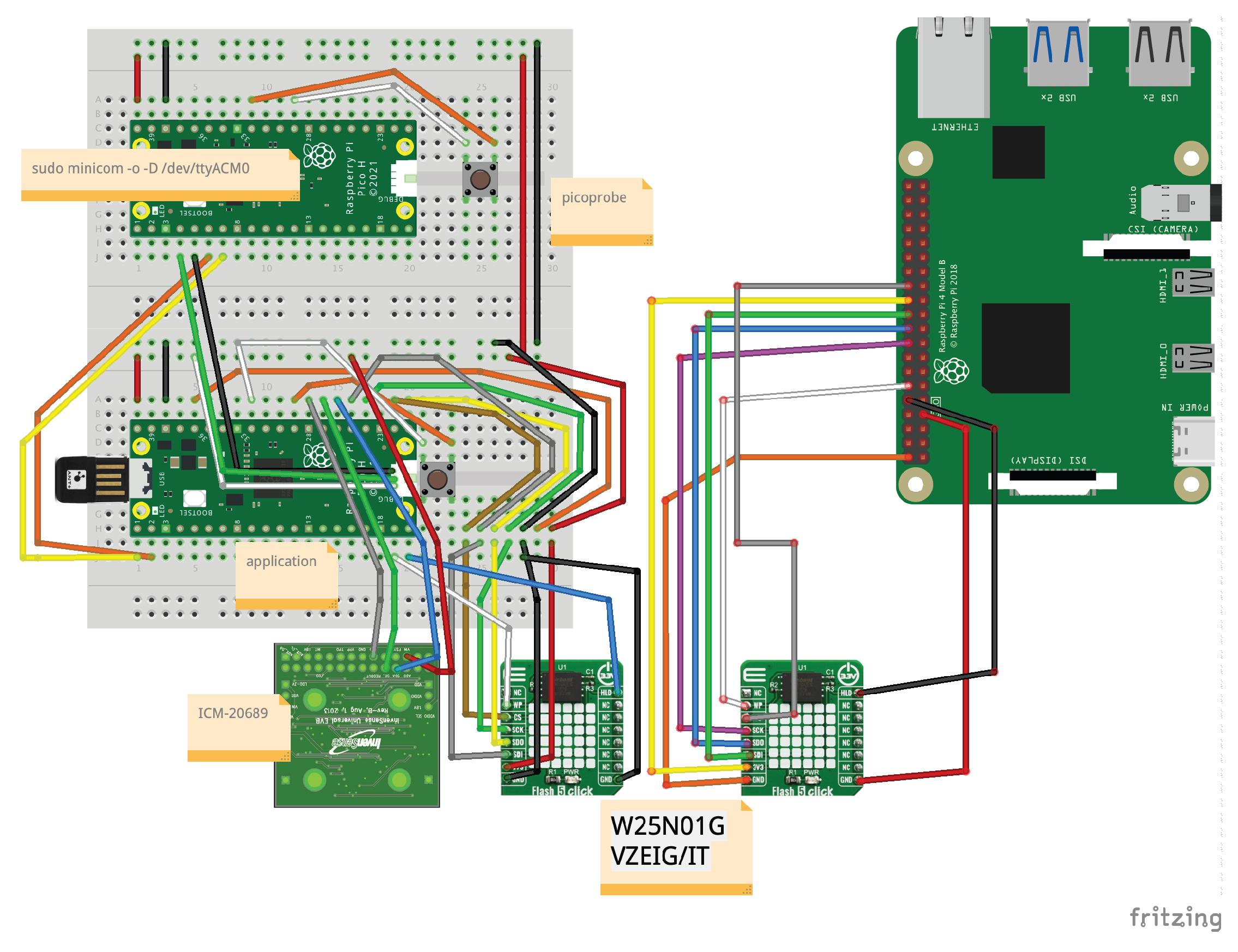
In this study, we constructed a prototype system to verify the feasibility of the proposed architecture. We adopted RP2040 (Raspberry Pi Pico) as the Child board, implementing low-power sensor logging processing using dual-core Arm Cortex-M0+ (133MHz) and 264KB SRAM. For the Mother board, we adopted BCM2711 (Raspberry Pi 4), executing computationally intensive tasks such as garbage collection, wear-leveling, and metadata consolidation with quad-core Arm Cortex-A72 (1.5GHz). W25N01GV (128MB SPI/NAND Flash) was used as shared non-volatile storage. The circuit connection image during Mother and Child board debugging is shown in Figure 19.
Due to budget constraints, full implementation of the hardware FSM coordination circuit was deferred, and evaluation was conducted using software-based mutual exclusion as an alternative implementation. Switching of SPI/NAND access rights between both boards was designed and implemented using a handshake mechanism via GPIO signals. Complete hardware FSM circuit-based deterministic ownership switching is left as future work, and this prototype demonstrated the basic principles of temporal locality optimization and multi-domain coordination. A loosely coupled file system for IoT devices—composed of microcontrollers with general-purpose interfaces and readily available SPI/NAND flash memory, without reliance on specialized components or instructions—is considered to have competitive advantages in specific domains from an economic rationality standpoint, particularly in terms of resilience to unexpected power loss.
14. Future Work
14.1. Integration of DeepSleep Function
In this PoC, RP2040’s DeepSleep function for long-term operation through low power consumption was not adopted (Figure 16). This was because the reset and reinitialization processing of the wireless communication module (CYW43) in RP2040 was judged to be too complex at the PoC stage. A design that achieves both the wireless module reinitialization sequence upon return from DeepSleep state and MXFS log continuity is an important future challenge.
14.2. Full Implementation of Hardware FSM
The FSM proposed in this study (Figure 2, Figure 3 and Figure 4) was logic-simulated in a Verilog HDL testbench environment, and timing validity was confirmed in the normal operation model. However, timing variations during power-on in actual hardware and initialization delays caused by sensor module state changes were not sufficiently evaluated in real operational environments. Additional verification through power control sequence testing and clock synchronization experiments during hardware implementation is required.
15. Source Code Publication
The source code for the proposed file system (MXFS) is publicly available at: https://github.com/xander-jp/mxfs 4
Repository structure:
- hw/ — Simulation for logical evaluation of FSM planned for hardware implementation
- sw/child/ — Child-side file system implementation (RP2040, BCM2711, macOS compatible)
- sw/parent/ — Parent-side formatter and verification tools
Appendix A. Reference: Power Consumption of Other Peripherals
The power consumption of peripheral devices used in this implementation is shown for representative devices. The inertial sensor (ICM-20689)5 has an active current consumption of approximately a few mA, and the LP39436-based LED driver similarly consumes approximately 0.35 mA in Active mode. The external non-volatile memory SPI-connected NAND Flash (W25N01GV) used has an operating current consumption of approximately 25 mA7. Furthermore, the ANT USB Stick (ANT+ dongle)8 is a low-power USB bus-powered device designed within the Low-power device range of USB 2.0 specification (maximum 100 mA, 5 V). In actual use, it typically operates at a current consumption of a few mA to 10 mA, making its contribution to overall system power consumption small.
All of these are smaller values compared to the power consumption dominated by the wireless communication module in this configuration, and are not major factors in overall system power consumption evaluation.
Appendix B. Reference: Commercial FS List
Table A1.
Small Footprint Commercial File Systems (Appendix).
| Tuxera Reliance Edge | |
|---|---|
| Log-structured + transactional, combining journal and log-structured approaches | |
| Renesas FAT File System | |
| Implements power-failure support within the scope of the FAT specification | |
| OSS no-OS FatFS(SD/SPI/RPi Pico) | |
| Implements power-failure support within the scope of the FAT specification | |
| HITACHI UltraFile | |
| Implements power-failure support within the scope of the FAT specification | |
References
- Yang, C.; Guo, C.; Zhao, M.; Cao, Z. A Zoned Storage Optimized Flash Cache on ZNS SSDs. arXiv. Oct 2024. Available online: https://arxiv.org/pdf/2410.11260.
- Rosenblum, M.; Ousterhout, J. K. The Design and Implementation of a Log-Structured File System. ACM Transactions on Computer Systems 1992, 10(No. 1), 26–52. [Google Scholar] [CrossRef]
- Alahmadi, A.; Chung, T. S. Crash Recovery Techniques for Flash Storage Devices Leveraging Flash Translation Layer, A Review. Electronics 2023, 12(6), 1422. [Google Scholar] [CrossRef]
- Tran, V. D.; Park, D. J. A Survey of Data Recovery on Flash Memory. International Journal of Electrical and Computer Engineering (IJECE) 2020, 10(no. 1), 360–376. [Google Scholar] [CrossRef]
| 1 | |
| 2 | |
| 3 | |
| 4 | |
| 5 | |
| 6 | |
| 7 | |
| 8 |
Figure 1.
Module Blocks.
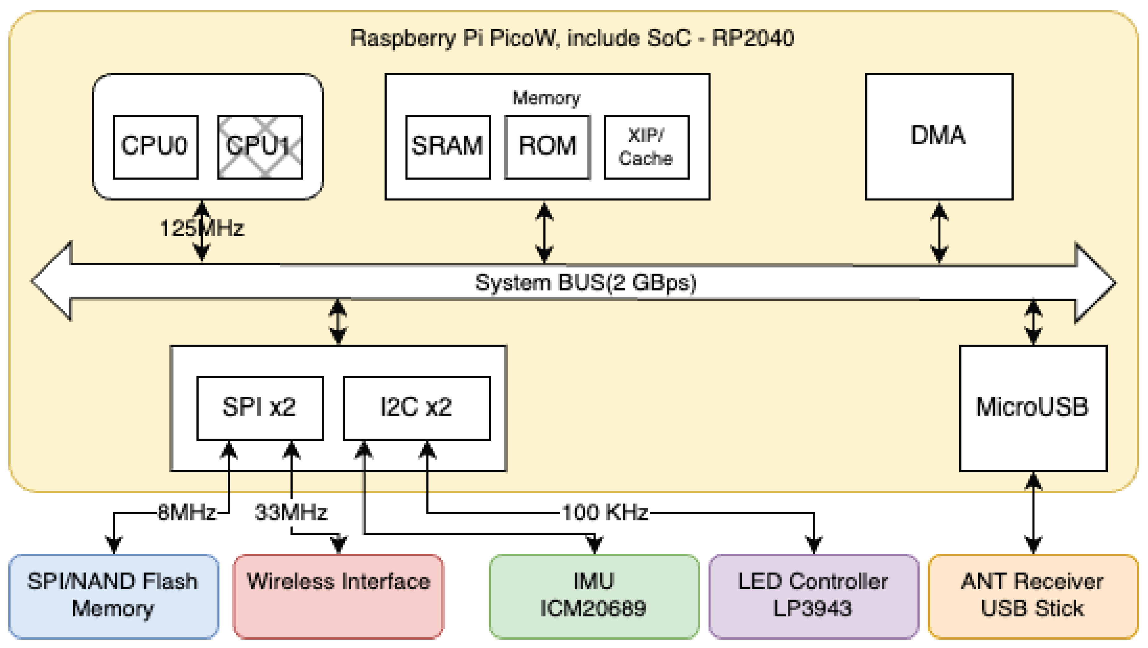
Figure 2.
FSM Circuit: C1 (Mother), C2 (Child), and Selector constitute a Moore machine.
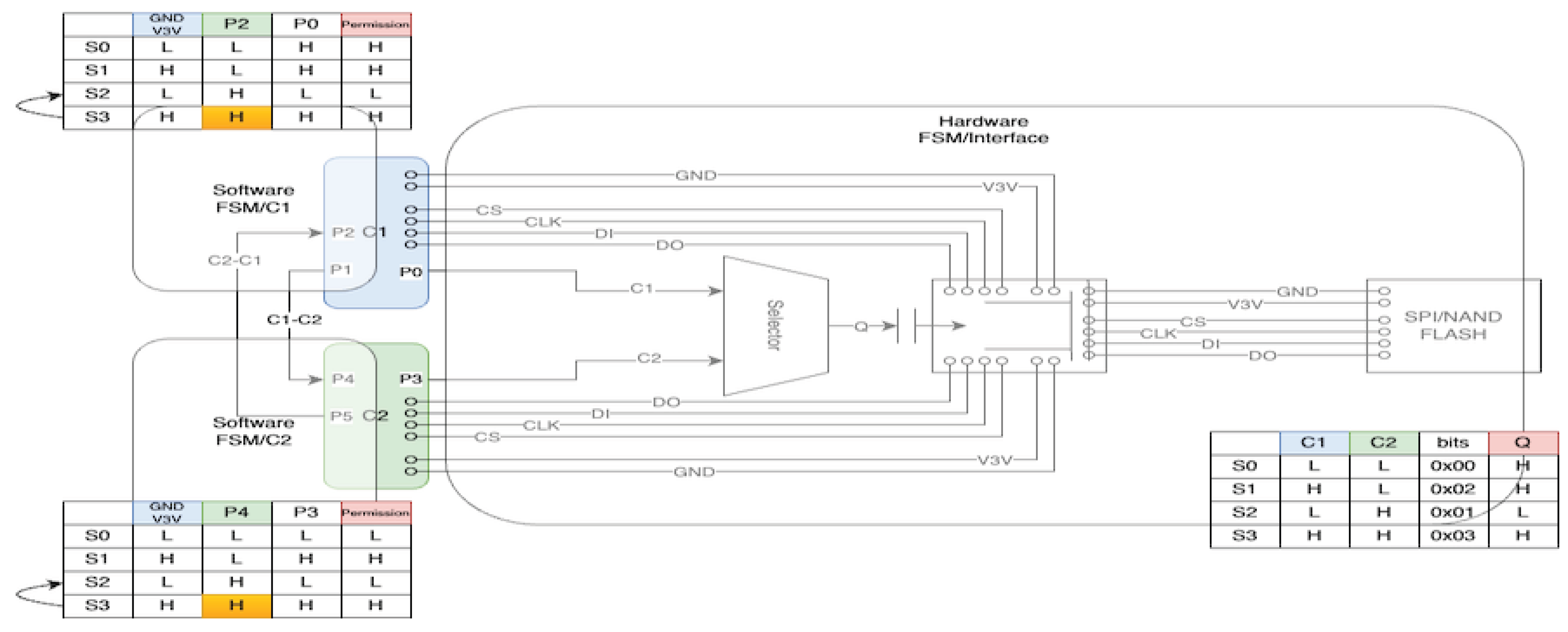
Figure 3.
Timing Chart: State Transitions, Ownership Switching.
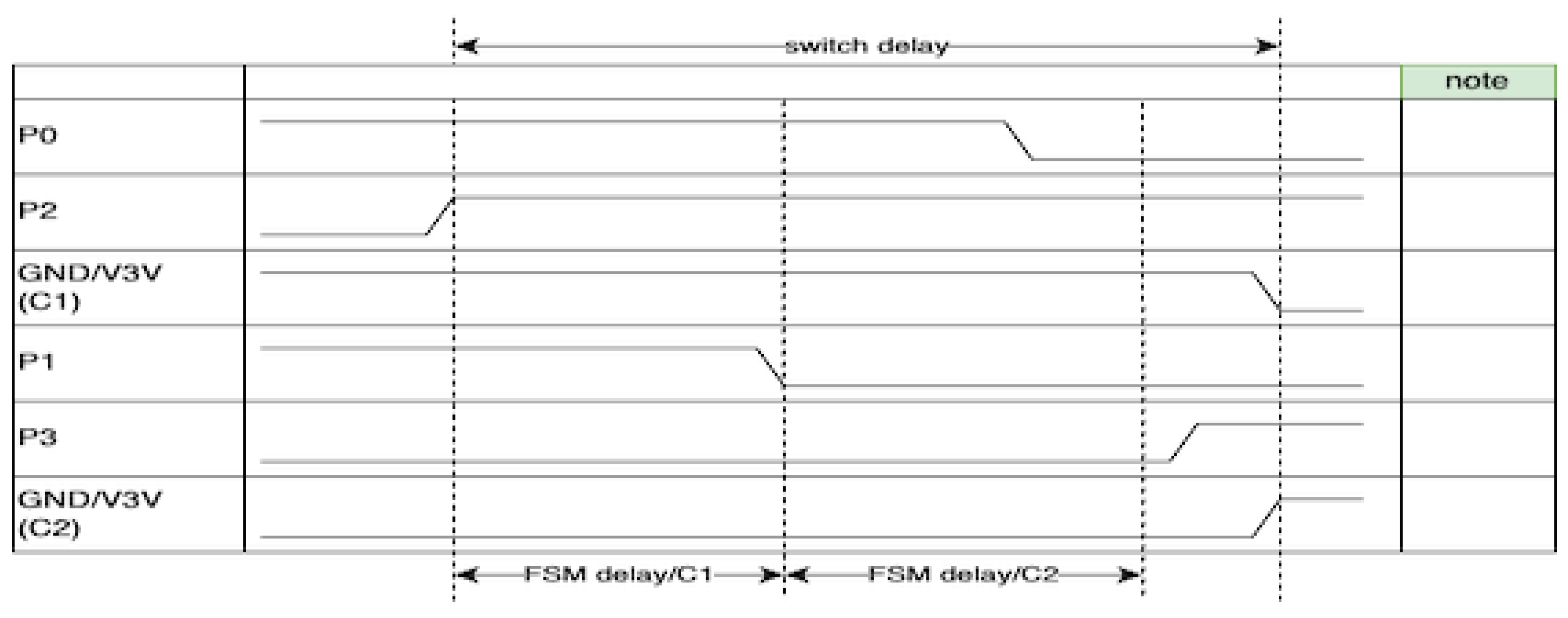
Figure 4.
FSM Coordination Switch: Physical switching of SPI bus via analog multiplexer.
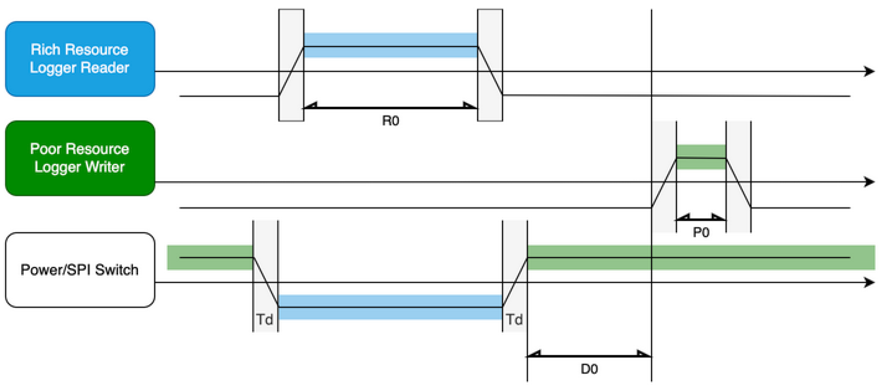
Figure 5.
Protocol Stack.
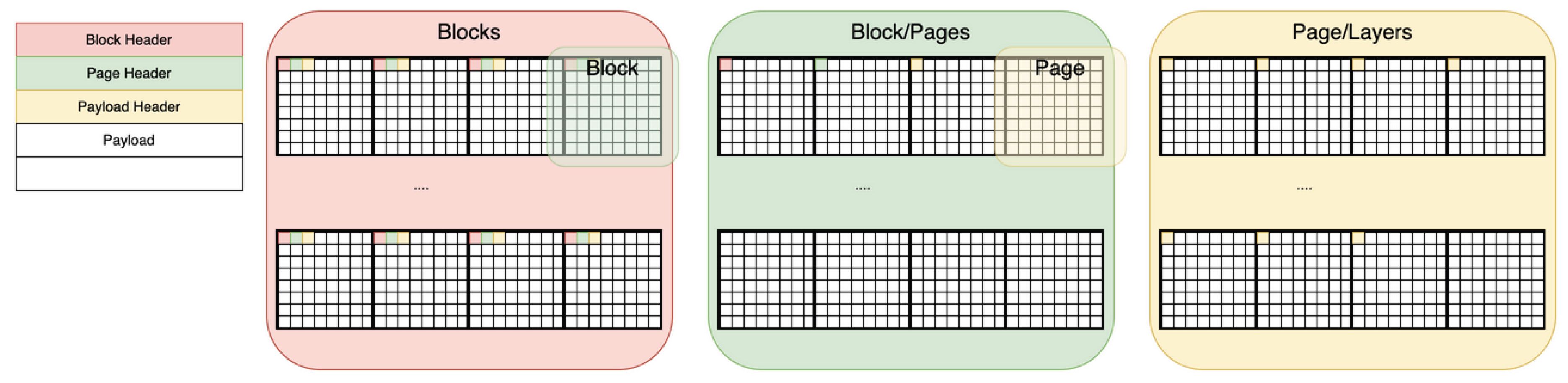
Figure 6.
Fast Mount Sequence.
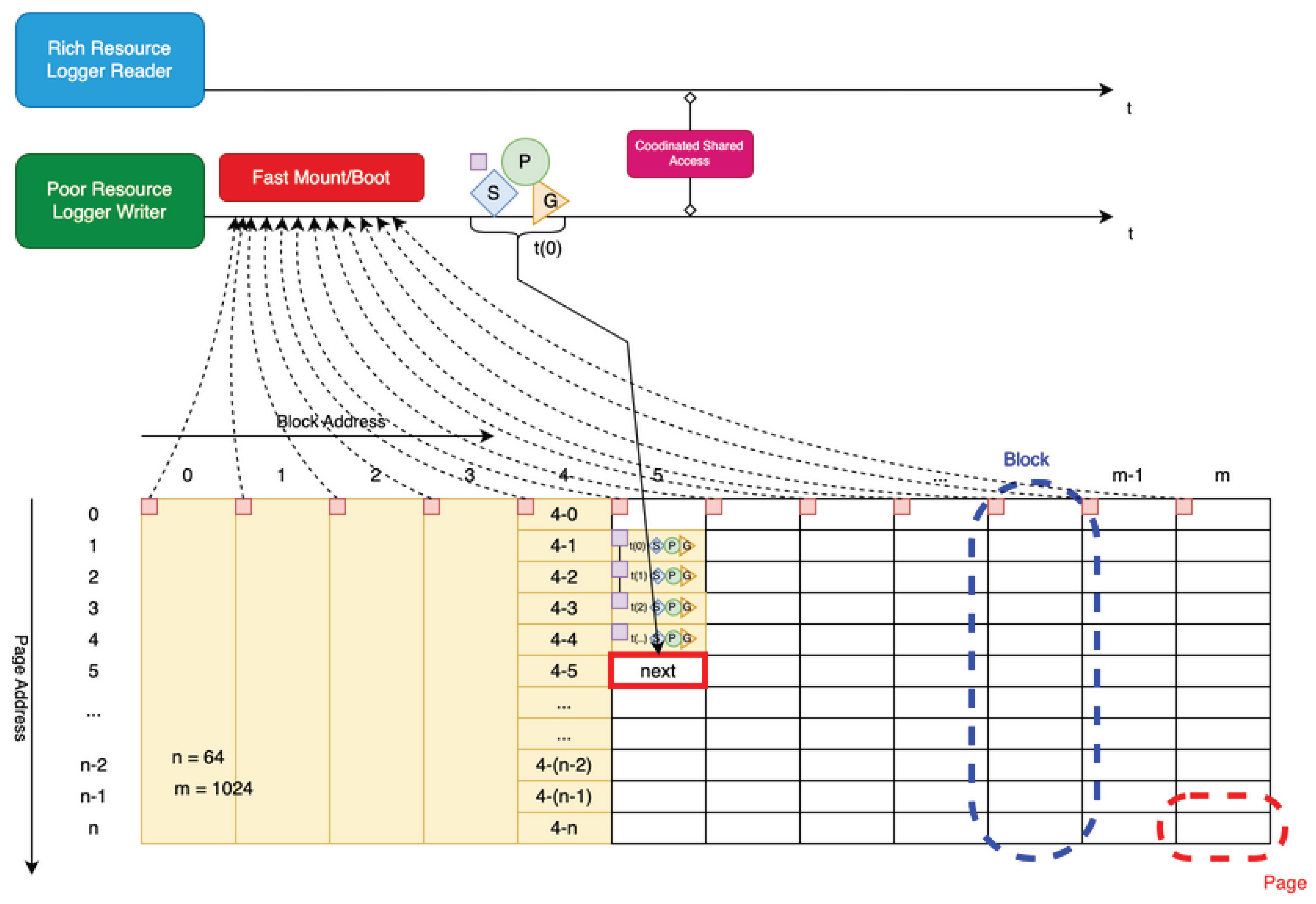
Figure 7.
Fast Mount Level.
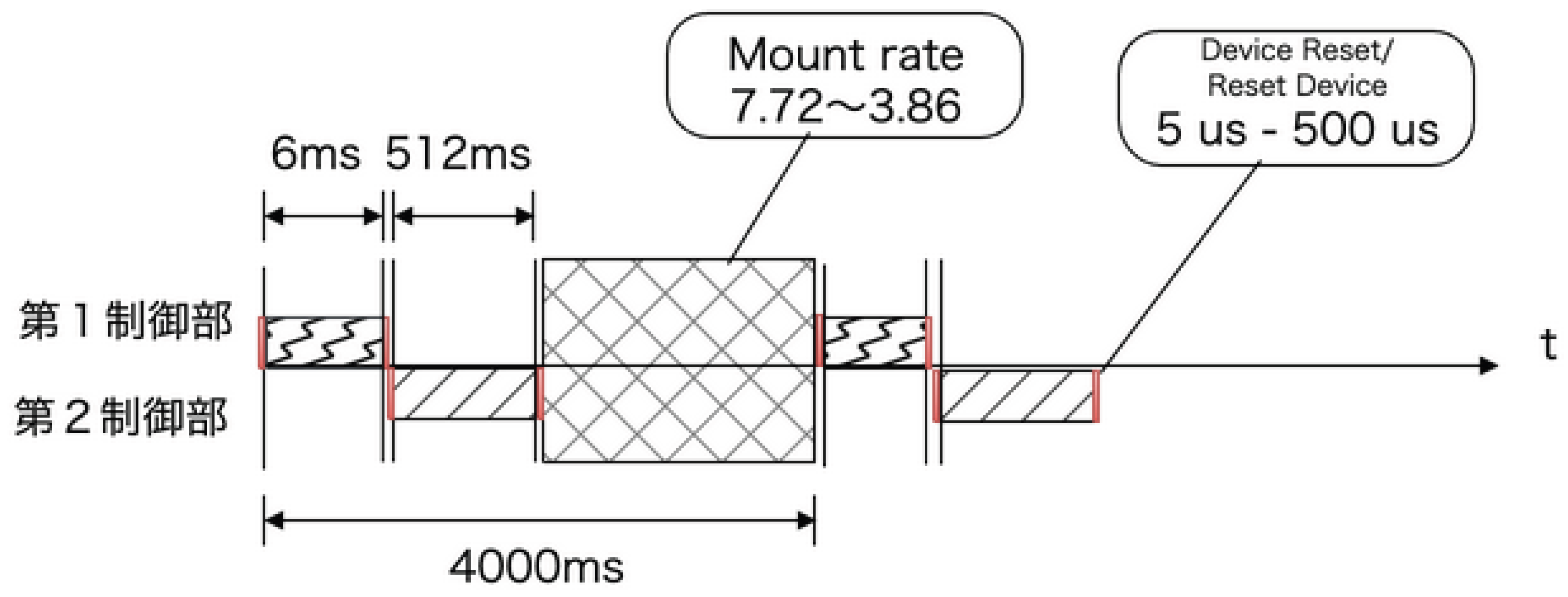
Figure 8.
Wear Leveling.
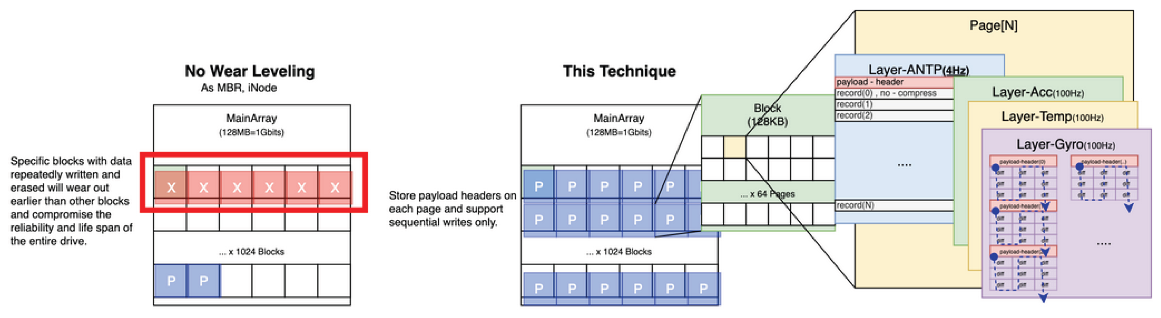
Figure 9.
Layer/Differential Architecture.

Figure 10.
Unexpected Power Loss.
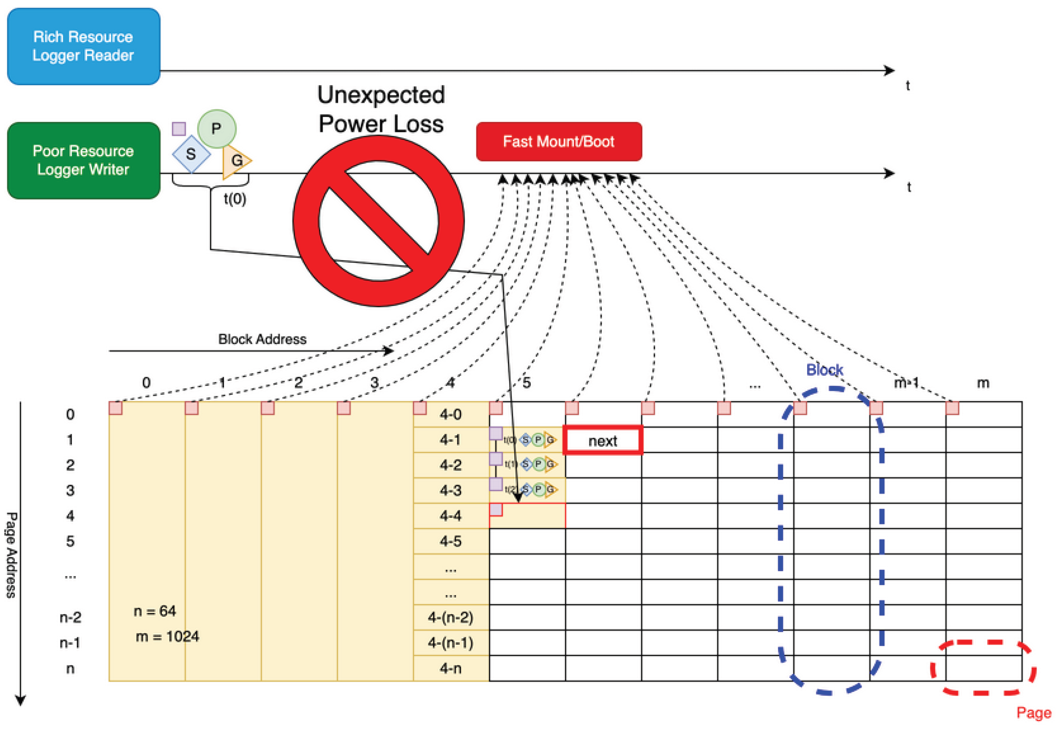
Figure 13.
Measurement Points.
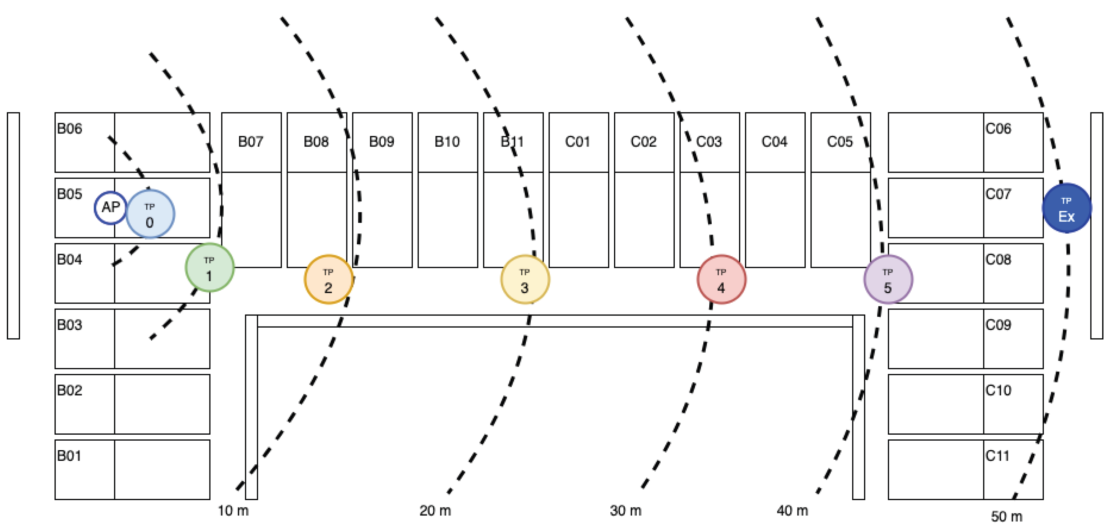
Figure 14.
Power Consumption by Area.

Figure 16.
Deep Sleep.
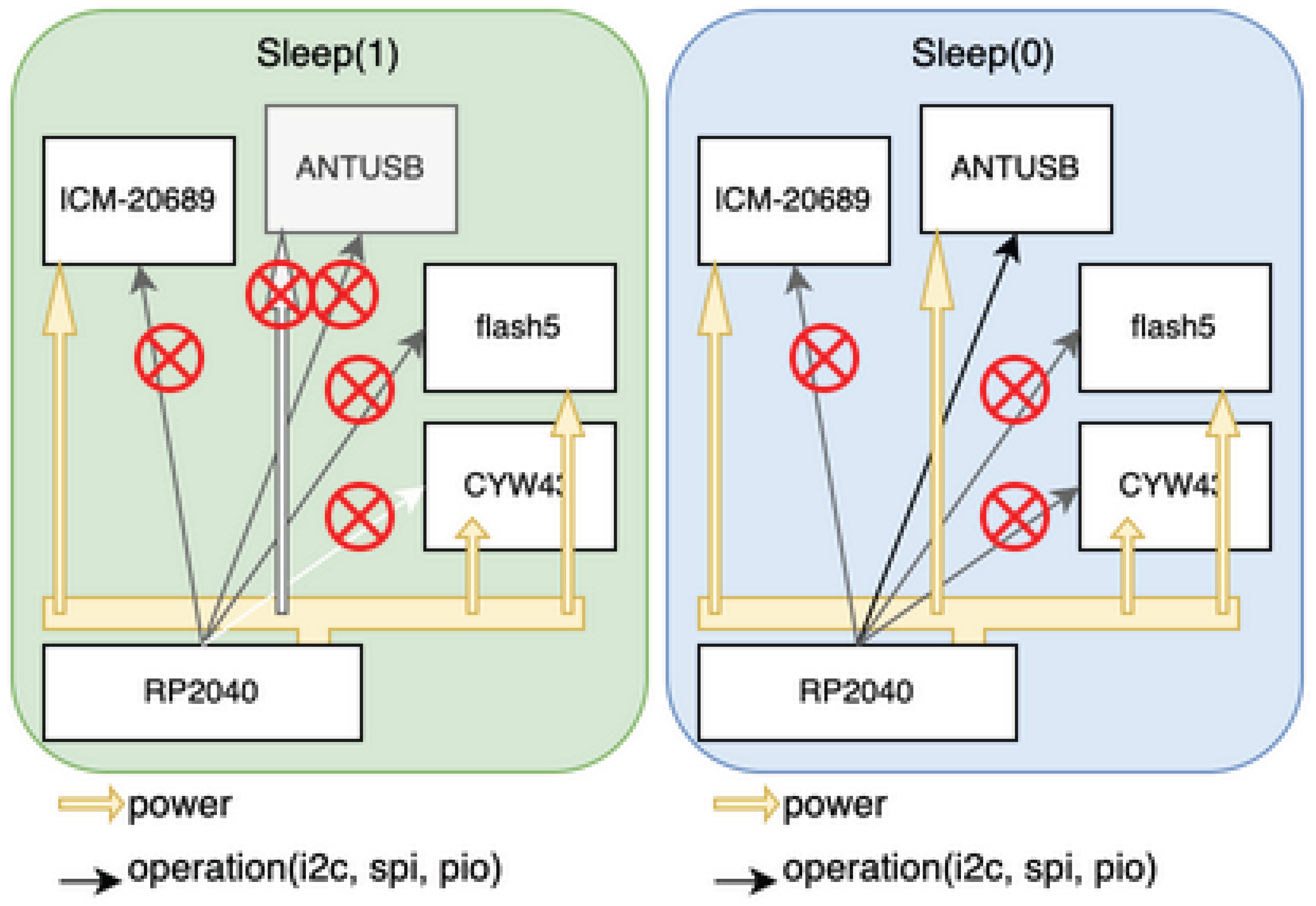
Figure 17.
Hardware-Cooperative Architecture.
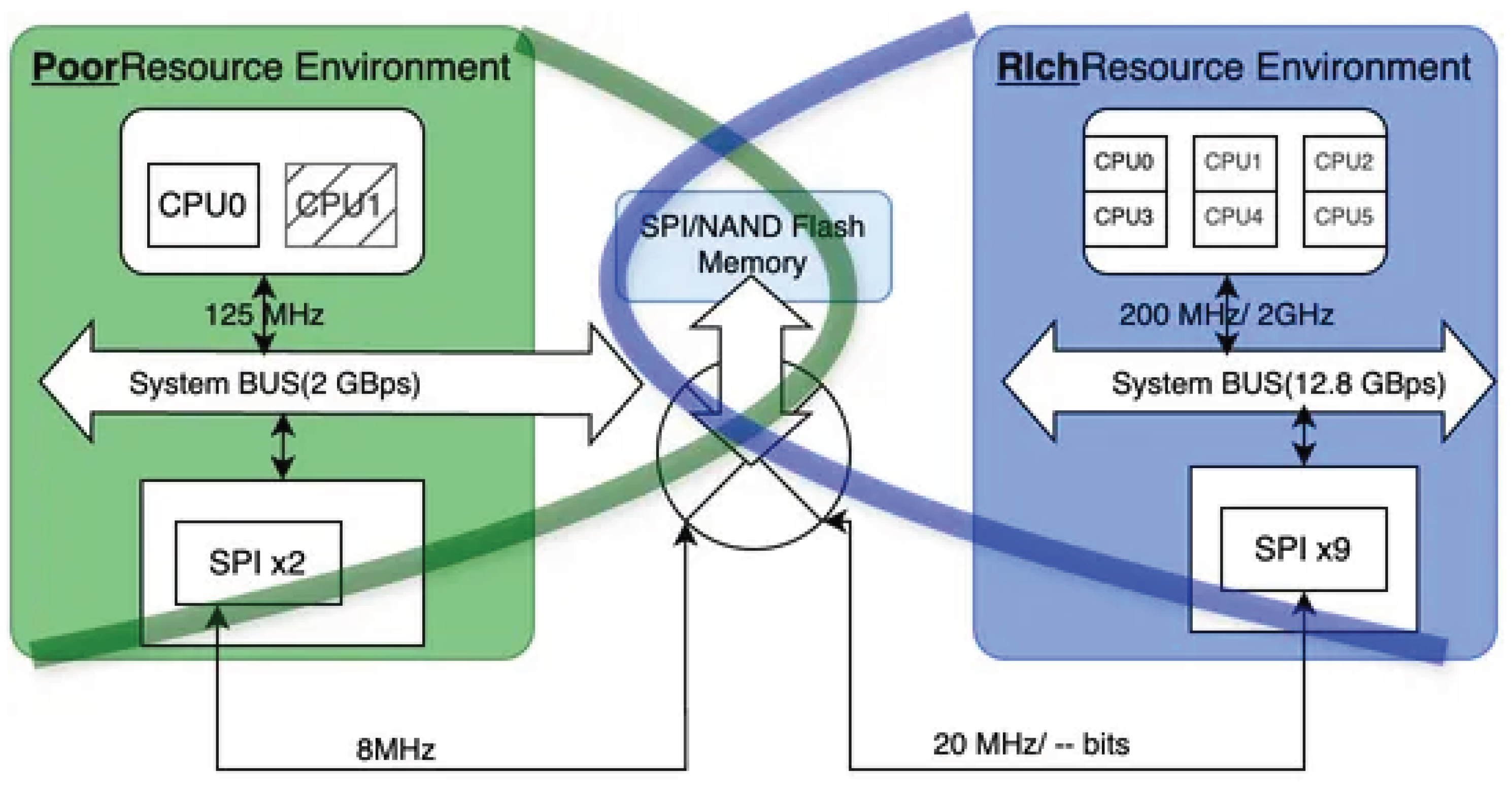
Figure 18.
Data Timing Chart.
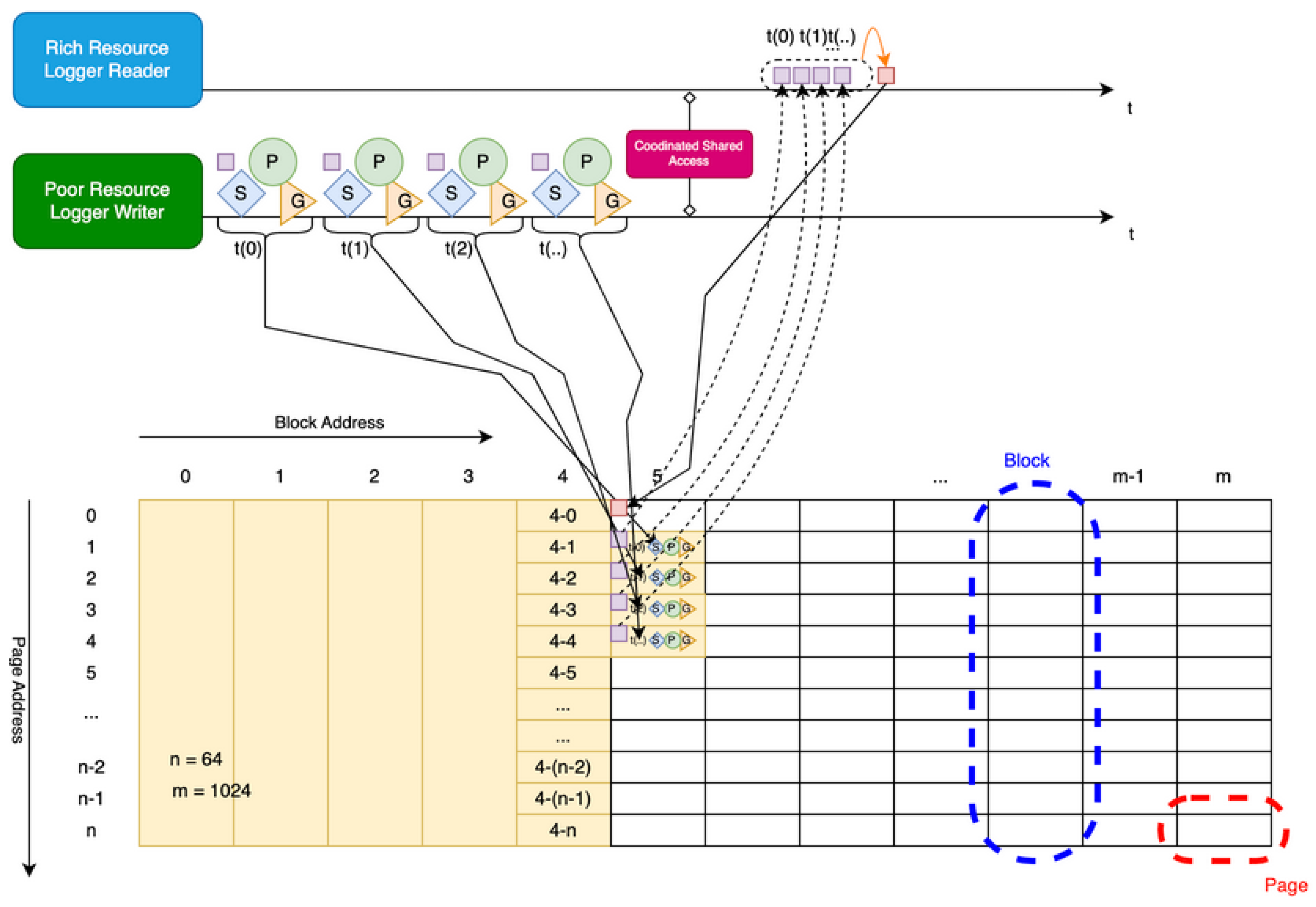
Figure 19.
Mother, Child Board Circuit Connection Image During Debugging.
Disclaimer/Publisher’s Note: The statements, opinions and data contained in all publications are solely those of the individual author(s) and contributor(s) and not of MDPI and/or the editor(s). MDPI and/or the editor(s) disclaim responsibility for any injury to people or property resulting from any ideas, methods, instructions or products referred to in the content. |
© 2026 by the authors. Licensee MDPI, Basel, Switzerland. This article is an open access article distributed under the terms and conditions of the Creative Commons Attribution (CC BY) license (http://creativecommons.org/licenses/by/4.0/).
Copyright: This open access article is published under a Creative Commons CC BY 4.0 license, which permit the free download, distribution, and reuse, provided that the author and preprint are cited in any reuse.


