

Submitted:
14 October 2025
Posted:
15 October 2025
You are already at the latest version
Abstract
Drones are becoming a very frequent and useful tool for emergency responders in supporting disaster management actions, but most emergency responders' fleets end-up in a plethora of drones with heterogeneous performances. In case of a major disaster all available resources are welcome. The allocation of task to each drone must be done taking into account the characteristics of the vehicle and of the payload, and must be done fast. In this work we present a methodology for the planning of drone trajectories for the surveillance of an area, using each available asset according to its potential and with the objective to obtain the full area scanned in the fastest possible time. This methodology accounts for no-fly zones that drones must completely avoid. Results show that, in less than 2 minutes, the trajectories of all the drones of an heterogeneous fleet can be generated to efficiently cover the area with a uniform precision, and less flight distance compared to the best state-of-the-art methods. The comparison of different area partition algorithms shows that it may be better to simplify the area for a better split despite the increase of area to cover.
Keywords:
drone
; emergency management
; disaster risk reduction
; area decomposition
; trajectory generation
1. Introduction
Based on reports from the Office for Disaster Risk Reduction (DRR) of the United Nations (UN) [1], over the last twenty years, 7,348 natural disaster events were recorded throughout the world. In total, disasters affected a total of over 4 billion people, with casualties summing up approximately million lives, an average of 60,000 per year. Furthermore, disasters cost approximately US$ trillion in economic losses worldwide. These concern only natural-hazard-related disasters, excluding biological, technological, and other human-related disasters. The current climate change situation predicts that the number of disasters will increase in the following years. UN Sustainable Development Goals aim to reverse climate change, but in the process the Earth needs to develop resilience strategies to reduce the risk of these catastrophic events.
Based on the Sendai Framework for Disaster Risk Reduction (DRR) 2015 - 2030 [2], the creation of knowledge and tools is needed to achieve the UN sustainability and resilience objectives. Sendai addresses the disaster risk reduction strategy in three dimensions: to prevent the creation of new risk, to reduce existing risk, and to increase resilience. In all three dimensions, the adoption of new technologies is essential to foster the success of the Sendai strategy.
Technologies that are well known in disaster risk management are computerised control centres from where commanders and politicians manage the emergencies. The quality of the decisions are directly related with the situational awareness, the existence and knowledge of actuation plan, and the assets available to deploy in the terrain. Satellites and Internet of Things (IoT) sensors help in the creation of situational awareness. However, satellites can be absent at the area of interest in the moment of the disaster, or visibility at the moment of maximum approach of the orbit can be reduced due to clouds, smoke, or lack of daylight. Ground sensors can be destroyed, or the communication network can have failures in the event of disasters. The use of drones is ideal to replace missing assets, providing data with high accuracy and at the desired time and place [3].
During the eruption of the Cumbre Vieja volcano in La Palma in 2021, drones played a crucial role in emergency response efforts [4]. They were deployed to monitor the progression of lava flows and assess the extent of damage in real-time. High-resolution aerial imagery helped authorities create accurate maps, allowing for better decision-making regarding evacuations and resource allocation. In addition, drones were used to measure air quality by detecting toxic gases, ensuring the safety of emergency teams working in hazardous areas.
After Hurricane Ian caused widespread devastation across Florida in 2022, drones became essential tools for damage assessment and recovery [5]. Emergency teams used drones to survey flooded areas and assess infrastructure damage, identifying the most critical locations in need of assistance. Search and rescue operations benefited from drones equipped with thermal imaging cameras, which helped locate stranded survivors, particularly in areas that were difficult to access by boat or helicopter. Utility companies also leveraged drones to inspect damaged power lines and expedite electrical restoration, significantly reducing the time required for repairs.
Following the devastating earthquake that struck Türkiye and Syria in 2023, drones played a key role in search and rescue missions [6]. Equipped with thermal cameras, they scanned collapsed buildings to detect signs of life, allowing rescue teams to focus their efforts on areas with the highest probability of finding survivors. Drones were also used for logistical support, transporting emergency medical supplies to areas that were inaccessible due to debris and infrastructure damage. In addition, in regions where communication networks had collapsed, drones provided temporary relay connections, allowing emergency teams to coordinate more effectively.
The PANTHEON project [7] is developing a digital twin to test emergency plans and train first responders about the correct use of collaborative decision making tools. Drones are recognised as an emerging asset for the situational awareness of an area under an emergency situation. As part of the PANTHEON toolset, planning the fleet of drones, in connection with the Command and Control Center (C2C), is a relevant contribution. This paper evaluates several methods for the allocation of area surveillance task to fleets of heterogeneous drones of different rescue teams, taking into account the characteristics of the vehicle and its payload. It proposes a new method for planning drone trajectories in a non-convex region while avoiding restricted areas. The final objective is to obtain the complete situational awareness of the disaster area in the minimum time, using all available resources.
This paper is organised as follows: Section 2 presents a literature review. Section 3 presents the methodology of the use of fleets of heterogeneous drones in emergency situational awareness, including contributions in requirements assignment, area decomposition, and trajectory generation. The results of the methodology for 100 areas worldwide using diverse composition of drone fleets and a comparison with a best-in-class Coverage Path Planning method for non-heterogeneous fleet of drones are presented in Section 4. Finally, the Section 5 discusses the results obtained for the different comparisons and concludes with future work.
2. Previous Works
The use of drones for emergencies has a huge background. Surveys [8,9,10] are a good summary and show the potential of drone applications in disaster management, search and rescue, and emergency deliveries. For instance, Inès et al. [11] propose a system that expands the capabilities of drones for remote and real-time sensing in emergencies, drones need to be integrated in the C2C as any other asset. Authors build a collaborative data delivery scheme able to transfer very accurate information to the C2C in near real-time. In [12] the authors evaluate several algorithms that divide an area and generate the trajectories to find the one that minimizes the power consumption of the drones. The challenge is to optimize the paths for efficiency, by minimizing the time and energy required to cover the entire area, which directly depends on the path length and the number of turns. In another recent article [13], as part of the initiative Automatic Fire Extinguishing and Prevention using Drones of the Department of Civil Defense of Jordan, authors propose the use of drones equipped with thermal cameras, sensors, and fire-suppressant delivery mechanisms to detect fire outbreaks early and respond instantly.
The challenge is identified in the literature as a Coverage Path Planning (CPP) problem [14]. A CPP problem involves finding a path that ensures that the entire space of a confined area is covered. In CPP the goal is to plan a route that allows a robot or agent to traverse all parts of the area without unnecessary repetition, while avoiding obstacles and restricting the amount of overlapping as needed for the image reconstruction.
The area can be simple and regular, with no holes, or can be complex like a non-convex area and have holes inside. For a simple and regular region it is sufficient to adopt a regular path pattern like back-and-forth survey, spiral, etc. Most proposed methods for complex areas are based on geometric division [15], on micro shifts following potential field forces [16,17], on particle swarm optimization (PSO) [18], and leader-follower models [19,20].
To solve the CPP problem with a multiple robot system (or swarms) different schemes have been proposed. Most of the literature addresses fleets of ground robots, but the proposed algorithms can also be applicable to drones. The geometric division is a common strategy and consists of two steps: first, the area to cover is divided into regions, and then an individual path planning is applied to each drone. By using more than one drone this strategy allows for the coverage of a very large area. Partition is also useful when the area is very complex because partition can simplify the geometry of the area into less-complex regions. Finding the most convenient partition is an additional challenge that previous literature has identified as a Polygon Partition Problem (PPP). For a good partition, the size of the resulting regions has to match the capabilities of the available drones of the fleet.
The classical planar polygon partition is extensively used. It is based on swap lines crossing the polygon from border to border. The improved sweep line Hert Lumelsky algorithm [21] has an open version extended for non-uniform partitions and non-convex polygons and is available under the name PODE. For convex polygons, an analytical method (PDAN) is proposed in [22]. This analytical method optimizes the compactness of the regions using also sweep line division, but directly from derivative formulae. It demonstrates to find optimal polygon decomposition in very fast execution time.
The Distributed Autonomous Robot Planning (DARP)[23] applies local optima decisions at the individual drone level, based on the shared knowledge of the environment. The method is able to generate the non-overlapping trajectory of each vehicle, for non-convex, complex-shaped areas using a grid-based division. Three optimization terms are considered: the completeness of the area coverage, the size of the grid nodes on the border of the polygon, and the alignment of the paths with the polygon’s borders. For each partition, the trajectory with fewer turns is generated, with some overlapping allowed. Compared with other state of the art methods, DARP reduces the length of the trajectories and the number of turns, at the cost of losing some small percent of the area coverage. The method is proposed for fix flight altitude and tested with ground vehicles. Apostolides et al. [15] extended the use of DARP for the heterogeneous division of an area.
A swarming formation scheme is proposed in [24] using the leader-follower model. The method is assessed for in-situ optimizing the collaboration of drones to provide a trusted situation awareness of an area under a disaster emergency. However, the particularities of aerial trajectories and the heterogeneity of the vehicles in the fleets are not fully exploited.
Miah et al. [25] provide a real-time implementation of an area coverage optimization algorithm for a team of heterogeneous mobile robots. These are small ground robots and heterogeneous in the sense that they have different actuator limits, physical dimensions, and processing capabilities. The method is based on geometric Voronoi tessellation and the application of state-feedback control law for actuator inputs of each robot that optimizes energy consumption.
The use of heterogeneous fleet of drones is the focus of this other survey [26]. It addresses specifically the collaborative use of multiple drones with real flight experiences and reports use cases of fleets of drones for floods and forest fires. It concludes that training is needed for commanders to understand the utility of drones and that tools need to be developed to facilitate optimal drone deployment over the terrain in stressful situations. Authors of [27] propose a conceptual design of a human-centered wildfire emergency response system including software, hardware, human components, their interactions, and their interfaces. But they only consider swarms composed of quasi-identical drones, and do not present training as an essential part of their system.
3. Materials and Methods
The objective of this work is to build a tool embedded in PANTHEON disaster risk reduction (DRR) platform to rapidly plan the deployment of a fleet of heterogeneous drones. The tool will target full reconnaissance of an area in a disaster scenario. The parameter to optimize is the time needed to cover the area. Since time depends on the flight distance and the number of turns, and those depend on the compactness of the region, we consequently will optimize those. As a result of this optimization, the energy consumption will also be reduced in most cases. The drone flights shall return a set of images that cover the full area with a specific pixel resolution, given as a ground sampling distance input value.
To effectively cover the specified area, we employ a three step method: first, the specifications of the available drones in the fleet are analyzed and compared against the area; second, we decompose the area into regions with defined proportions; and finally we plan the 4-dimensions trajectories (4DT) of each drone in each region, including the round trip trajectory from and to the drone take-off location.
3.1. Fleet analysis
The fleet is assumed to consist of heterogeneous drones. Basically, different range, speed, camera field of view and pixel resolution. Figure 1 shows the performance metrics that influence the calculation of the maximum area that a given drone can fly. Sensor characteristics, required image overlapping, and the desired ground sampling distance are used to set the flight altitude and the spacing between flight tracks in the back-and-forward drone trajectory, forming a collection of parallel sweep lines. Given this input, the drone’s maximum range and its corresponding speed, we calculate the maximum covered area.
The formalization of the process is as follows: first, we identify the desired ground sampling distance for the images to be captured. This value is determined by the size of objects that need to be detected in the images, such as people, vehicles, or infrastructure damages, such as debris or cracks. This value, along with some characteristics of the camera, namely the vertical and horizontal fields of view and the output image resolution, will determine the drone’s flight altitude, which is essential for flight planning. For simplicity, it is assumed that the camera maintains a nadir (downward-facing) orientation. A more advanced method that accounts for the pitch angle of the camera is detailed in Zerrouk’s thesis [28]. For a more straightforward approach, equations 1, 2 and 3 illustrate how to derive the altitude Above Ground Level from the desired ground resolution .
where is the Horizontal Footprint and HIR is the Horizontal Image Resolution.
The is calculated as follows (eq 2):
where is the height Above Ground Level and is the Horizontal Field of View.
The for each drone is then obtained using the formula in eq 3:
Other parameters to determine before planning are: the sweep spacing that separates two adjacent flight lines and the capture distance that separates two consecutive image captures on the same flight line. These two distances are used to transform the area of interest into a grid of points. These will be later referenced by the horizontal and vertical separation distances of the grid points.
Calculating these two distances involves a mapping-specific parameter: the between captures. For zero , the sweep lines are separated by a distance equal to the horizontal ground footprint , whereas for non-zero , the sweep lines are separated by a distance less than . The formulas for calculating these distances are Equations 4, 5, 6 and 7:
with:
and
Finally, once is determined, eq 8 is also used to calculate the maximum area that the drone can cover :
where is the Maximum Flight Distance provided for each drone.
The first-respondent stations provide the take-off point from which the drones depart and to which they return after the flight. They can correspond to buildings hosting a fire brigade, a police station, or also to mobile stations, such as drones that are transported and operated from a truck. In most cases, these stations are located outside the area of interest.
During this first step and to determine the distance to reach the area, the initial location of the fleet is used as a starting point. Since the area has not yet been partitioned, there is no information about which region each drone will be assigned to. Considering the worst case, the solution consists of taking the farthest point of the polygon as the entry point. The length of the two routes, towards and back from the region to scan, are subtracted from the drone’s range to ensure that it does not run out of power.
Finally, if the sum of for all drone i is greater than the polygon area then a proportional reduction is applied to all of them. Conversely, if the sum is less than the area, a new area requirement is added that will represent the area that cannot be covered with the current resources. We will tag this area as ’Not Assigned’.
At the end of this step, a list of drones’ names and their respective area requirements is returned.
3.2. Area decomposition
The decomposition process utilizes as input the polygon that delimits the area of interest. This polygon may include holes (i.e. restricted zones) that specify no-fly zones. Other external no-fly zones can be specified as input. The second input is the list of the available drones and their capabilities (e.g. the area that an UAV can cover). The objective of the decomposition process is to create partitions of suitable sizes. These partitions can be non-convex and shall exclude any existing holes within the area of interest.
We use several polygon partition algorithms: a grid-based bottom-up algorithm (NPD) from [29], the improved sweep line Hert Lumelsky algorithm (PODE)[21] and the analytical decomposition (PDAN) [22], with the latter running only over the convex-hull of the original polygon. All of them split a polygon into two regions according to the area requirements. Executing the split algorithm iteratively for all drones completes the area partition.
The main contribution on this part is the addition of a preliminary step in which the order of the split requirements follows a balanced strategy. This is a recursive algorithm that takes the list of the not-yet-assigned area requirements and divides them into two sets. The objective is to obtain two sets with similar area requirements to avoid small regions at the beginning.
The strategy starts sorting all area requirements from the largest drone capabilities to the smallest; for each of them, a greedy policy assigns each new requirement to the set that has less accumulated area; finally the split algorithm creates the most compact division for the areas of the two sets. The method is recursively repeated for each region that it is still composed of more than one drone. The subdivision continues until the area requirements belong to one of the original drone requirements. Figure 2 shows an example with five drones with different capabilities. They are initially divided into two sets for a first division, and further subdivisions are recursively done until there is a region for each drone.
3.3. Path Planning
The proposed path planning method uses as input one or more polygons that delimit the regions to cover. These polygons may include holes (i.e. obstacles or restricted zones) that specify no-fly zones. Other inputs are information on the available drones, their assigned region, and their performance characteristics.
Our path planning method is able to manage convex and non-convex input polygons. It generates multiple potential paths and then selects the one with the minimum turns and a short distance. It ensures maximum area coverage while avoiding restricted zones. The path planning process is carried out in two main stages. First, a grid of points and a set of undirected graphs are generated for a rotated version of the polygon at various rotation angles. Then, trajectories are computed within these rotated polygons and the best trajectory is selected. The final part of this section will provide details on how no-fly-zones are avoided.
Stage a) Grid and graph creation
Each region generated by the area decomposition algorithm is represented as a polygon. The polygon is assumed to lie in a planar coordinate system with the Y-axis oriented toward the north and the X-axis toward the west. For every segment of this polygon, the planning algorithm first computes the rotation angle  required to align the segment with the X-axis of the plane. This alignment angle is then added to the N discrete angles of the set where N is a configurable parameter of the algorithm. The resulting N angles are used to rotate the polygon accordingly, as shown in Figure 3.
For each rotated polygon with the summed angles (angle for alignment and angle from the set), the algorithm creates a grid of points parallel to the X-axis of the plane. These points start at from the bottom point of the polygon boundaries and are vertically separated at a distance interval of . Points in the same horizontal line start and end at from the outermost boundaries of the polygon. They are distanced by except for the last point that can be distanced by less than .
Grids transform the environment into a discrete structure, significantly simplifying the application of graph-based algorithms. This discrete approach is one of the key reasons grids are widely adopted in path planning methods. Their effectiveness has been thoroughly investigated in numerous studies [30,31,32].
All points located within the polygon are classified as pass points, whereas any points outside the polygon are considered no-pass points. Examples of no-pass points include those lying within holes in the polygon or those positioned between two segments that form a concave angle. Figure 4 shows different grids resulting from different rotation angles.
Points in the same horizontal line represent a sweep line of the drone trajectory, and every pass point marks the position where the camera captures each new image.
Upon generating the complete set of points for a given rotated polygon, an undirected graph is constructed, wherein the nodes are the external and internal vertices of the polygon (internal vertices are those defining any holes). Initially, the graph edges consist of the polygon segments (external border and, if relevant, internal perimeter of the holes). The graph structure may be augmented at this step by introducing two pass points surrounding every no-pass points’ segment along the same sweep line as auxiliary nodes (this helps define a route in the graph to go around the no-pass points). These nodes are then linked to existing graph vertices to facilitate the computation of a shortest path between them (see Figure 5).
Stage b) Path calculation
In this stage, for each rotated polygon and its associated points obtained during the Grid and graph creation stage, two paths are calculated as potential drone trajectories. Each path begins at the drone’s starting position and leads to one of the entry points represented in Figure 4. These points are endpoints of the line that starts at the bottom of the polygon. That line will be referred to as the lowest sweep line. If a path crosses one or more no-fly zones, an alternative path is computed to avoid them. More details on area avoidance will be provided later in this section.
Arriving at an endpoint of the lowest sweeping line, each path continues following a systematic back-and-forth pattern from the bottom to the top, passing through each point designated as a pass point. When two pass points are separated by one or more no-pass points, or the segment connecting them is not entirely contained within the polygon (i.e., it intersects the edges of the polygon), both points, whether adjacent or not, are added as nodes in the graph. They are then connected to polygon vertex nodes that can be reached without crossing any internal or external polygon boundaries (see Figure 5, right plot).
After updating the graph with these two auxiliary nodes, the algorithm searches for the shortest path that connects them, restricted to traverse exclusively through the polygon vertices. This shortest path search is performed using the A* algorithm, selected for its computational efficiency and its proven ability to quickly determine optimal paths. The resulting shortest path is then integrated into the global trajectory currently being constructed.
Once all pass points have been visited, the point corresponding to the initial position of the drone is appended as the final destination to the global trajectory. If this return path intersects one or more no-fly zones, an alternative route is computed to ensure complete avoidance of restricted areas like before.
Figure 6.
Two trajectories generated for a rotated partition, each entering from a different endpoint of the lowest sweeping line and avoiding any crossing with polygon boundaries.
Figure 6.
Two trajectories generated for a rotated partition, each entering from a different endpoint of the lowest sweeping line and avoiding any crossing with polygon boundaries.
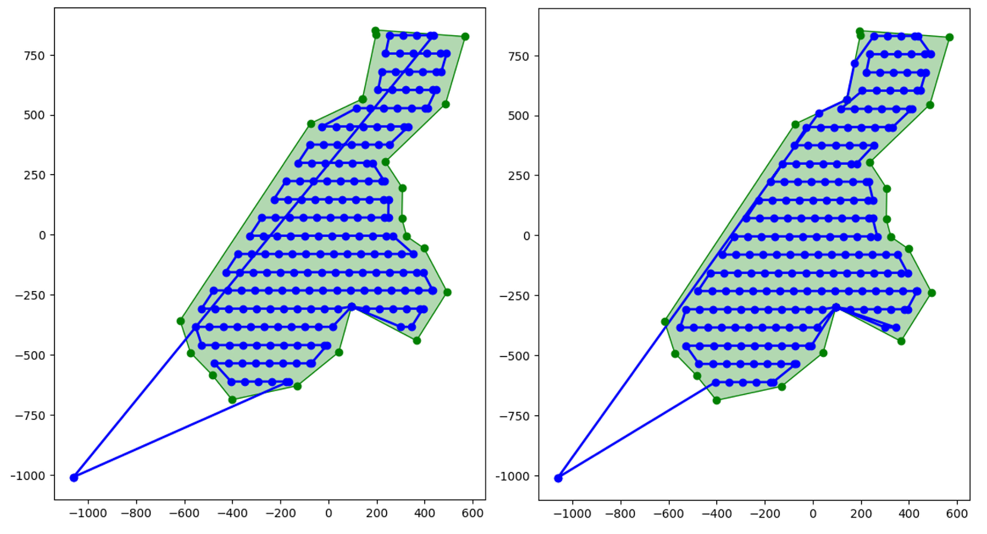
The two trajectories, each passing from different endpoints of the lowest sweeping line, lead to a different number of turns and different flying distances. These trajectories are evaluated against each other, as well as against trajectories generated for the same partition under different rotation angles. The trajectory selected for a partition polygon is the shortest among the possible solutions with the lowest number of turns.
where is a function that sorts a list of trajectories by their distances and calculates the number of turns for a trajectory t.
After computing the optimal trajectories for all partitions, the overall performance of the mission is evaluated based on a set of predefined metrics. These metrics include the percentage of area coverage, the total number of turns, the cumulative flight distance across all drone paths, and the mission duration, defined as the maximum flight time among all individual drone trajectories.
Trajectory refinement: Avoidance of no-fly zones
This refinement is applied when the drone encounters one or more restricted areas, both while heading toward the partition from its initial position and when returning to it after completing the partition scan. It is part of the path calculation stage.
Restricted areas can vary in number and configuration. They can be holes within the polygon to be scanned or adjacent polygons that may be located along a flight path. For all cases, a detour path must be computed to avoid them.
For this, we construct a visibility graph [33] where each node is a vertex of the polygons that define the restricted areas. Edges are added between nodes only if the straight line connecting them does not intersect the interior of any restricted zone.
Once all valid connections are established, the graph is ready to be used to calculate avoidance paths for any trajectory generated by the algorithm. In fact, to connect the starting position of a drone to an entry point in its partition, we simply add two new nodes that represent these positions in the graph. Each is then linked to all accessible nodes that do not require crossing restricted areas (see Figure 7). The shortest path between these two new nodes is then computed using the A* algorithm.
3.4. Example of Fyli Scenario
This section presents an example of the complete process using the Fyli scenario setup, on one of the pilots prepared in the PANTHEON project [7]. It defines an area of interest that needs to be urgently monitored after a disaster. The scenario also defines the available resources (the drones, their characteristics, and their base station).
3.4.1. Area of Interest
The city of Fyli, Greece, has been selected as the area that needs to be monitored after a disaster. Fyli is in the North-West of Athens that had some emergency episodes in the past and has been selected as one of the PANTHEON project pilots. Figure 8 shows Fyli and its surroundings.
The municipality of Fyli has almost 50 thousands of inhabitants and an area of . The area of interest in case of an emergency is the populated area, highlighted in the figure. This area is contained within a polygon of .
The example assumes a first-responder station located in the east of the area and excludes a non-populated area in the north-west (see Figure 8).
3.4.2. Drones fleet
We assume that the first-responder crew in charge of the emergency has a diverse drone fleet with heterogeneous performances. On day-by-day activities they may use the drone with the best performance, but in a large-scale emergency all available drones will be deployed because this can help to react faster.
Table 1 shows a list of seven drones with their characteristics, selected for the Fyli showcase. These are typical small drones (except for the Yuneec H520E) that may be used by many firefighters or police crews today. Some values were obtained directly from the official documentation, while others were derived based on available technical information. In cases where specific data were unavailable, reasonable approximations were made to support the calculation of drone capability.
The drone speeds listed in Table 1 are those used to determine the Maximum Flight Distance and will serve as a reference for all subsequent calculations.
3.4.3. Algorithm Steps
The first step is to calculate the area that each drone model can cover. We need to subtract twice the distance between the drone initial position and the farthest point of the polygon. Then, assuming a target equal to , the remaining range capability is converted to area using the calculated sweep distance (SD).

Table 2.
Maximum surface of each drone, and area required once proportionally reduced to cover the Fyli area (265.5 ha)
Table 2.
Maximum surface of each drone, and area required once proportionally reduced to cover the Fyli area (265.5 ha)
| Drone type | Maximum surface (ha) | Area requirement (ha) |
|---|---|---|
| Parrot Anafi AI | 136.5 | 44.8 |
| DJI MINI 4 Pro | 101.3 | 33.2 |
| DJI Phontom 4 Pro V2.0 | 64.2 | 21.0 |
| DJI Air3 | 134.2 | 44.0 |
| Skydio X2E Color | 59.1 | 19.4 |
| Skydio X10 | 250.3 | 82.0 |
| Yuneec H520E | 63.3 | 20.1 |
The second step is the partition of the area according to the values obtained above. Three potential partitions are shown in Figure 9 using different partition algorithms: On the left PODE, on the middle NPD and on the right PDAN, this last using the convex-hull and ignoring the holes. The first row shows the non-balanced results of the decomposition algorithm and the second row the balanced partitions.
Observe that the most clean partition is PDAN with the proposed balanced strategy. Nevertheless, the area polygon has been converted into its convex hull, since PDAN can only manage non-convex polygons with no holes. Note also that PODE is not programmed for the balanced strategy. Finally, the effects of the balanced strategy on NPD seem unclear. More details about partition results will be presented in Section 4.
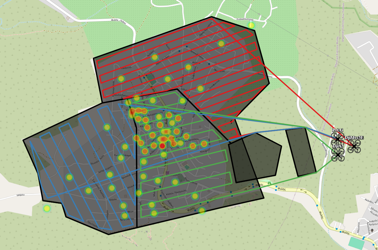
The trajectory generation step follows after the polygon partition. The results of this third step are the trajectory lines shown in Figure 10. All trajectories (lines in blue) depart from and return to the first responder’s unique location. Note that the density of the capture points (shown as points within the path lines) and the separation of the sweep lines are very different, depending on the quality of the camera onboard each drone. Additionally, the Figure 10 highlights several no-fly zones that drones must avoid in order to successfully reach the designated area.
4. Results
4.1. Metrics and Evaluation Setup
Generalization of the goodness of the algorithm needs to be done using objective metrics. The most essential metric is the total time required to obtain images of the full area of interest. This includes the flight time of all drones (see in eqn 10), from the first departure () to the last return (). The time required to obtain the complete map of the area from the images taken by the drones is beyond the scope of this work.
The partition algorithms aim at maximising the region compactness. We also define the Compactness (C) as the average compactness of all regions assigned to drones (see eqn 11).
where is the compactness for the region R assigned to drone d, defined as:
We will also look at the number of turns () and the total flight distance () by accumulating the individual values of each drone trajectory. While corresponds directly to the length of the trajectories, the number of turns is determined by counting the angles formed by each three consecutive points on the trajectory that are not equal to .
Finally, the metric accounts for the quality of the result, showing the percent of the total area explored. It is determined based on both the and the . It also takes into account the yaw rotation of the drone at the time each image is captured. This metric considers all captured images and evaluates the percentage of the area effectively covered by these images. Some scenarios may end with an area that is not visited during the unique flight of the drone fleet if its combined range is not high enough. In others, coverage may come very close to 100% without fully achieving it, mainly due to tiny regions with negligible area that are missed by drone imagery. When these small gaps are absent and the number of drones is sufficient, the full coverage is achieved.
4.2. Evaluation Set-Up
To evaluate the effectiveness of the proposed method, a comprehensive series of tests was performed for each stage under a variety of scenarios.
The parameters of the path planning algorithm, the ratio and the number of rotation angles N, are set to 0.5 and 3, respectively. The flight altitude is computed as described in Equation 3 for a equal to . We set an additional parameter, the maximum allowable flight altitude, at 120 meters, to comply with the current regulation. If exceeds it, the value is truncated.
For the partition algorithms, we need to define the area tolerance. This is the difference margin allowed between the requested area and the actual region obtained, and particularly for NPD, the number of Steiner points used to set the triangulation grid size. The default parameter values are for the tolerance and 30 for the number of Steiner points.
4.3. Homogeneous Fleet Algorithm Validation and Comparison
We evaluated the performance of our combined methods against the Energy Aware MultiUAV Coverage (EAMC) algorithm proposed in [12], in which a cell decomposition is followed by a solver to compute the multiple set traveling salesman problem. The code is open and the solution works for homogeneous drone fleets. We used the original paper test scenarios and extended the test by adding the Fyli scenario used in Section 3.4, as shown in Figure 11.
The drone model selected for the Fyli scenario is Parrot ANAFI AI. Its corresponding battery model and other physical characteristics were recovered from [34] while the other scenarios preserved their original drone settings. We also assume that all drones take off from the same starting location for the two algorithms.
The algorithms are tested using an equal number of drones and identical sweep distances in each scenario, as presented in Table 3. The distance that separates the trajectories from the polygon boundary maintained during flight is set to 50% of the sweep distance. This distance is designated as the lateral offset in Table 3.
Both methods use the rotation operation. The EAMC uses two parameters: the number of rotations applied to the polygon, which is set to 3, and the rotation per cell, with values provided in Table 4. In our method, the number of rotation per segment N, defined in the Grid and graph creation stage, has been also set to 3. For the decomposition algorithm, EAMC uses Boustrophedon decomposition, and we use NPD with the balanced approach.
Additional configuration options related to the algorithms and their implementation are summarized in Table 4. They were adjusted for convenience to the shape and size of the original polygon.
The results of the two algorithms are summarized in Table 5. Each line has the result of one of the scenarios. On the left are the results of the EAMC and on the right our method. For EAMC, we computed the number of turns and the flight distance for comparison. Our method also provides flight time and coverage percentage as quality metrics.
Observe that the best metrics values are highlighted in bold. The number of turns in all but two scenarios is higher for EAMC, and the proposed algorithm consistently yields shorter flight distances compared to the benchmark algorithm. In the island scenario, the only one where the flight distance is higher in our method, only one drone is used without any decomposition. Since the polygon contains a hole, the trajectory must navigate around it, resulting in a longer travel distance. The area coverage metric, not given in EAMC, is consistently near-complete or fully achieved by our method. The time to end the mission is between a minute and 25 minutes, depending on the size of the area and the number of drones used, but very good for an emergency response and situational awareness construction.
4.4. Heterogeneous Fleet Performance Analysis
The results for the heterogeneous fleets is divided into five subsections: first subsection presents the dataset used, then there is a subsection with the partial results of each of the 3-step of the method. Finally, subSection 4.4.5 provides some insight of the algorithm complexity.
4.4.1. Dataset and Scenario Generation
We perform further analysis using 100 polygons created ad hoc for this work. The dataset is publicly available[35] and contains polygons created from cities all over the world and named after them. The areas range from million to 30 million and can have holes inside, up to a maximum of 2. Figure 12 shows an example of four of them. Convex hull is needed for the PDAN algorithm, which can only manage partitions of convex polygons without holes. Comparing the size of the areas with the area of their convex hull we obtain an average increase of of the area.
From each polygon, we created 4 scenarios with random fleets selected from a drones dataset and an increasing number of vehicles (5, 10, 15 and 20 drones). The position of the fleet is somewhere around the polygon, always out of its borders.
4.4.2. Area Requirements Calculation
Before the area partition, the range of the drones is conveniently updated to ensure that drones will be able to reach the polygon and return to the base independently of the assigned area. is set to 2 and the sweep line distance (SD) and the capture distance (CD) are calculated for each drone. With all of this data, the maximum surface area that each drone could fly is calculated.
The plot in Figure 13 shows the box plots of the total area of the polygons and the total area that each fleet of small drones can cover. Observe that there are some scenarios where the area that a fleet can cover is lower than the area of the polygon, especially for the fleets with less drones.
In consequence, a number of the generated scenarios have not sufficient resources to cover the area. Table 6 shows them per fleet size. Observe that, in general, the fleets of 5 to 10 drones can not handle the coverage of more than half of the areas generated. Even for the largest fleet size, with 20 drones, almost one third will fail.
4.4.3. Partition Algorithm Comparison
We tested three split algorithms, PODE[21], NPD[29] and PDAN[22] and calculated the ability of each to perform the best area assignment. We also evaluate the benefits of applying the balanced strategy.
Figure 14 shows the distribution of the area coverage (in percentage) for each of the 3 algorithms and for each of the 4 sizes of the fleets. For all algorithms, the first quartile of the area coverage increases as the number of drones increases, but NPD is the one where better coverage is obtained when the number of partitions grows. On the contrary, PDAN has the worst results, as expected given the increase of the convex hull area.
To further analyze the algorithms quality Figure 15 shows the differences between the area distribution entered as a requirement to the split algorithm and the final area assigned to each drone. Results are given as box plots per each algorithm and per each fleet size.
Observe that the medians are zero or very close to zero, which shows the good quality of all the hetereogeneous split algorithms. We can also observe that the distribution of the values of the differences is less as the number of drones increases, because the choices of the algorithm also increase. By comparing the amplitude of the box plots and the number of outliers, we can conclude that NPD is the best algorithm when adjusting the area requirements with the assigned area.
Next, we evaluate the balanced strategy presented in Section 3.2 showing the results of compactness for two of the three algorithms. Figure 16 shows side-by-side the compactness box plots obtained by the original (NPD and PDAN) and the balanced split (B_NPD and B_PDAN). On the top for NPD and on the bottom for PDAN, and detailed per fleet sizes. Looking at the differences, we observe that the balanced strategy always increases compactness. The balanced strategy gets also much less negative outliers (those with very low compactness). The strategy applied to the PDAN algorithm has even more positive effects with compactness medians growing from to . In consequence, the rest of the results of the section use the balanced strategy in NPD and PDAN.
Figure 17 shows the final results of the three partition algorithms tested, with the average compactness of the regions. The plot is a box plot showing quartiles, outliers and median, and is organized by algorithm and per fleet size. Observe that the PODE shows the worst compactness, while PDAN has the best, at the cost of flying more area that strictly needed.
4.4.4. Trajectory Generation Metrics
We measured the number of turns and the total distance to flight as defined in Section 4.1 for all algorithms and all fleet sizes. Figure 18 shows the number of turns (left) and the distance to flight (right) as average (top) and box plots (bottom). We observe that both turns and total distance grow as the number of drones increase and that the best algorithm again is PDAN despite the increase of the total area to cover of the convex hull.
But the most important result from the perspective of the end users, who need to have situational awareness as fast as possible of the emergency area, is the total mission time as shown in eq. 10 which measures the flight time from the departure of the first drone til the landing of the last drone. Figure 19 shows the average for the 100 polygons of the total mission time detailed by partition algorithm and grouped by fleet size. Observe that PDAN generally provides faster flight times, although the differences are not very significant.
It is worth noting that the time reduction when using four times more resources (increasing the fleet from 5 to 20 drones gives only time reduction) is clearly below expectations. We further analyzed the time distribution of each scenario by dividing the time to go towards the region of the polygon to be covered, the time to flight a scan pattern over the region and the time to return to base once the region is covered.
Figure 20 shows the mission time for each flight phase per each algorithm and per fleet size. The behavior for the three algorithms is the same: the times to route to and to get back from the region are practically constant through the different fleet sizes, while the scan time is the only part that decrements. Note that the time minutes in this plot are all lower than those in Figure 19. The reason is that in this plot we calculate the average of all drones, while in the other the total mission time is calculated using the time of the slowest drone.
Finally, we present the mission time results considering only those scenarios in which the fleet has the capacity to cover the full area. Refer to Table 6 to see that this subset represents almost half of the scenarios: From the original 100 polygons, only 29 polygons can be covered by the fleet of five drones, while 73 by the fleet of 20 drones. Evaluating only these polygons, we can observe (see Figure 21) that the time reduction of the full mission is more appreciable with the introduction of new resources.
4.4.5. Computational Performance
Figure 22 shows the execution times of the method,separating phases 2 (polygon partition) and 3 (trajectory generation), with the execution time of phase 1 included in phase 3. Phase 2 executions have been performed with an Intel i5-1135G7 (4 Cores) laptop with 16 GB of RAM, while phase 3 was executed with Intel(R) Core(TM) i5-7300HQ CPU @ 2.50GHz 4-Core laptop with 8GB of RAM.
The largest execution of the partition algorithm is less than 7 seconds (PODE, 5 drones), and the median is in seconds. In comparison, the trajectory execution time is longer, with medians around 15 seconds and the worst cases reaching more than 90 seconds. In any case in less than 2 minutes, the method is able to produce the flight plan of up to 20 drones for any area. Note that PODE split and trajectory generation times have low sensitivity to the number of drones in the fleet. Also, observe that the trajectory generation runs faster for PDAN, the method that produced regions with highest compactness.
5. Discussion
In the event of an emergency, all available resources can help to facilitate the task of first responders and speed up the correct decision-making with the situational awareness that drones can provide. Speed is very important and it is advisable having a fleet planning tool that integrates the method proposed in this paper. During the first phase of the method, one can already know if the available fleet is sufficient and, if not, request more resources from other teams. Alternatively, a new polygon of smaller size can be created to better delimit the area with the highest interest, so that the available fleet can progress according to the experts’ criteria.
The requirement for using the method is to have an up-to-date database with the drone fleet characteristics. Then, at the moment of emergency, some operator has to create the shape of a polygon that contains the area to cover and set the current position of the fleet. Any geographical information system (GIS) can be used for this. The algorithm accepts geojson format, but any other similar standard format for geographical shapes could be used.
If the polygon is convex, the results show that Balanced PDAN is the best option for the split. If it is non-convex, but flying outside of the polygon or disregarding the holes is possible, then balanced PDAN over the convex hull is again the best option. The first responders in charge shall make a decision about this. If holes and polygon limits shall be kept, then we recommend the Balanced NPD. In any case, the balanced strategy has shown to improve the results.
For path planning, the presented method outperforms the best state-of-the-art method to the moment, creating trajectories that cover to 100 % of the area with fewer turns and less distance, and being able to avoid any forbidden area inside and outside the region to scan.
The method still has some improvements to make it more practical to first responders. When the available fleet has not enough capabilities to cover the area it may be necessary to plan the replacement of batteries as part of the task allocation algorithm. New fleet information, specifying the time to recharge or replace batteries of each drone shall be specified and used in the new planning.
The take-off location was assumed to be shared for all the vehicles of the fleet, but in a large-scale emergency more than one first responders bodies will be collaborating, each with their own fleet that will probably have different departure points. The partition algorithms can improve their response adding a new constraint: to split the area taking into consideration also the distance from the departure point. This new constraint can also help to speed-up the time to reach the area, which in this work is in sequence of vehicles. Separating the fleet strategically in different departure points will allow to reach the area by flying in parallel.
The terrain surface altitude, the wind direction or the sun reflections may also be taken into consideration when generating the trajectories. None of this elements have been considered but they are very relevant for the quality of the images and the actual flight time. Current trajectories calculate the altitude as relative to ground, but for terrains with high slopes this can imply a flight with many ascend and descend that consumes batteries faster, while following the terrain contour lines could be more efficient.
The compactness is a metric that has been largely used in decomposition algorithms, but further analysis about the relationship between flight time and compactness is desired. A new metric could be defined to better anticipate the flight time of the drones fleet and that could produce a better version of the analytical algorithm.
Finally, the emergency responders have a special necessity to know about status of the ground transportation network after a disaster. The ground transportation network (roads, railways, streets) are the main resource used to massively evacuate large number of people. A new strategy to follow a network of segments could to be very helpful at the second phase of the emergency, once the situation awareness is achieved, the damages are known and well-located, and first responders start their movements on the territory. A fleet of drones maintaining the information about the status of the ground transportation network will help to avoid the collapsed ways.
Author Contributions
Conceptualization, investigation and writing, I.Z., E.S. and C.B.; methodology, C.B.; software, I.Z., E.S., C.B. and G.H.; validation, resources and supervision, G.H and E.P.; All authors have read and agreed to the published version of the manuscript.
Funding
This work has been partially funded by the European Union’s Horizon Europe program under PANTHEON project with grant number 101074008, the Ministry of Science, Innovation and Universities of Spain under grant PID2023-152053OB-C21
Data Availability Statement
One hundred polygons have been generated around cities from all around the world. Polygons are generally non-convex and can have holes inside. Each polygon has the original shape and its convex-hull, and has been extended with 4 fleets of increasing size, from 5 to 20 UAS, creating a total of 800 scenario files. Finally, the polygons have been partitioned with 3 algorithms, resulting in a total of 1200 sets of trajectories. Datasets with polygons, drone fleet, partitions, and trajectories are available at ZENODO at https://doi.org/10.5281/zenodo.15746579. ALL DATA are in GEOJSON format.
Acknowledgments
Authors acknowledge the support given by Toni Calvo in creating the 100 polygons dataset, Jim Sharples and Michail Karamousadakis for their active participation in the project, and Younes Moumen for his valuable technical advice.
Conflicts of Interest
The authors declare no conflicts of interest.
Abbreviations
The following abbreviations are used in this manuscript:
| 4DT | 4-dimension trajectory |
| C2C | Command and Control Center |
| CPP | Coverage Path Planning |
| DARP | Distributed Autonomous Robot Planning |
| DRR | Disaster Risk Reduction |
| EAMC | Energy Aware MultiUAV Coverage |
| GSD | Ground Sampling Distance |
| IoT | Internet of Things |
| NPD | Non-convex Polygon Decomposition |
| PDAN | Polygon Decomposition by Analytics |
| PODE | Polygon Decomposition |
| PPP | Polygon Partition Problem |
| UAV | Unmanned Aerial Vehicle |
| UN | United Nations |
References
- Van Loenhout, J.; Below, R.; McClean, D. The human cost of disasters: an overview of the last 20 years (2000–2019). Technical report, Centre for Research on the Epidemiology of Disasters (CRED),United Nations Office for Disaster Risk Reduction (UNDRR), 2020.
- Center, A.D.R. Sendai framework for disaster risk reduction 2015–2030. Technical report, United Nations Office for Disaster Risk Reduction: Geneva, Switzerland, 2015.
- Kucharczyk, M.; Hugenholtz, C.H. Remote sensing of natural hazard-related disasters with small drones: Global trends, biases, and research opportunities. Remote Sensing of Environment 2021, 264, 112577. [Google Scholar] [CrossRef]
- Román, A.; Tovar-Sánchez, A.; Roque-Atienza, D.; Huertas, I.; Caballero, I.; Fraile-Nuez, E.; Navarro, G. Unmanned aerial vehicles (UAVs) as a tool for hazard assessment: The 2021 eruption of Cumbre Vieja volcano, La Palma Island (Spain). Science of The Total Environment 2022, 843, 157092. [Google Scholar] [CrossRef] [PubMed]
- Manzini, T.; Murphy, R.; Merrick, D. Quantitative Data Analysis: CRASAR Small Unmanned Aerial Systems at Hurricane Ian. In Proceedings of the 2023 IEEE International Symposium on Safety, Security, 2023, and Rescue Robotics (SSRR). IEEE; pp. 7–12.
- Ozturkcan, S. Technology and Disaster Relief: The Türkiye-Syria Earthquake Case Study. In Innovation; IntechOpen: Rijeka, 2023. [Google Scholar]
- Grabmaier I, Bittner S, K.S.e.a. Enhancing community participation in Disaster Risk Management: Recommendations for an inclusive approach. Open Res Europe. [CrossRef]
- Sanz-Martos, S.; Lopez-Franco, M.D.; Alvarez-Garcia, C.; Granero-Moya, N.; Lopez-Hens, J.M.; Camara-Anguita, S.; Pancorbo-Hidalgo, P.L.; Comino-Sanz, I.M. Drone applications for emergency and urgent care: a systematic review. Prehospital and disaster medicine 2022, 37, 502–508. [Google Scholar] [CrossRef] [PubMed]
- Daud, S.M.S.M.; Yusof, M.Y.P.M.; Heo, C.C.; Khoo, L.S.; Singh, M.K.C.; Mahmood, M.S.; Nawawi, H. Applications of drone in disaster management: A scoping review. Science & Justice 2022, 62, 30–42. [Google Scholar] [CrossRef] [PubMed]
- Kumar, K.; Kumar, N. Region coverage-aware path planning for unmanned aerial vehicles: A systematic review. Physical Communication 2023, 59, 102073. [Google Scholar] [CrossRef]
- Inès, J.; Annett, W.; Simone, D. Manual for CEMS-rapid mapping products. Publications Office of the European Union, Luxembourg, 2020. [Google Scholar]
- Datsko, D.; Nekovar, F.; Penicka, R.; Saska, M. Energy-aware multi-uav coverage mission planning with optimal speed of flight 2024. 9, 2893–2900. [CrossRef]
- Alkhatib, A.A.; Jaber, K.M.; Al-Madi, M. A Proposed Automatic Forest Fire Extinguishing and Prevention System Using Drones. In Proceedings of the 2024 IEEE International Humanitarian Technologies Conference (IHTC). IEEE; 2024; pp. 1–6. [Google Scholar]
- Cao, Z.L.; Huang, Y.; Hall, E.L. Region filling operations with random obstacle avoidance for mobile robots. Journal of Robotic Systems 1988, 5, 87–102. [Google Scholar] [CrossRef]
- Apostolidis, S.D.; Kapoutsis, P.C.; Kapoutsis, A.C.; Kosmatopoulos, E.B. Cooperative multi-UAV coverage mission planning platform for remote sensing applications. Autonomous Robots 2022, 46, 373–400. [Google Scholar] [CrossRef]
- Iqbal, M.M.; Ali, Z.A.; Khan, R.; Shafiq, M. Motion Planning of UAV Swarm: Recent Challenges and Approaches. In Aeronautics; IntechOpen: Rijeka, 2022. [Google Scholar]
- Wu, Y.; Yin, H.; Chen, X.; Zhang, M. Multicircuit route planning for UAVs performing the terrain coverage task. IEEE Internet of Things Journal 2024, 11, 23765–23779. [Google Scholar] [CrossRef]
- Skrzypecki, S.; Tarapata, Z.; Pierzchała, D. Combined PSO methods for UAVs swarm modelling and simulation. In Proceedings of the Modelling and Simulation for Autonomous Systems: 6th International Conference, MESAS 2019, Palermo, Italy, October 29–31, 2019, Revised Selected Papers 6. Springer, 2020. pp. 11–25.
- Lee, J.H.; Jeong, S.K.; Ji, D.H.; Park, H.Y.; Kim, D.Y.; Choo, K.B.; Jung, D.W.; Kim, M.J.; Oh, M.H.; Choi, H.S. Unmanned Surface Vehicle Using a Leader–Follower Swarm Control Algorithm. Applied Sciences 2023, 13. [Google Scholar] [CrossRef]
- Wang, J.; Wang, D. Particle swarm optimization with a leader and followers. Progress in Natural Science 2008, 18, 1437–1443. [Google Scholar] [CrossRef]
- Skorobogatov, G.; Barrado, C.; Salamí, E.; Pastor, E. Flight planning in multi-unmanned aerial vehicle systems: Nonconvex polygon area decomposition and trajectory assignment. International Journal of Advanced Robotic Systems 2021, 18, 1729881421989551. [Google Scholar] [CrossRef]
- Skorobogatov, G.; Barrado, C.; Salamí, E. Multi-Robot workspace division based on compact polygon decomposition. IEEE access 2021, 9, 165795–165805. [Google Scholar] [CrossRef]
- Kapoutsis, A.C.; Chatzichristofis, S.A.; Kosmatopoulos, E.B. DARP: Divide areas algorithm for optimal multi-robot coverage path planning. Journal of Intelligent & Robotic Systems 2017, 86, 663–680. [Google Scholar] [CrossRef]
- Papakostas, L.; Geladaris, A.; Mastrogeorgiou, A.; Sharples, J.; Hattenberger, G.; Chatzakos, P.; Polygerinos, P. Optimized Area Coverage in Disaster Response Utilizing Autonomous UAV Swarm Formations. In Proceedings of the 2025 33rd Mediterranean Conference on Control and Automation (MED); 2025; pp. 630–635. [Google Scholar] [CrossRef]
- Miah, M.S.; Knoll, J. Area coverage optimization using heterogeneous robots: Algorithm and implementation. IEEE Transactions on Instrumentation and Measurement 2018, 67, 1380–1388. [Google Scholar] [CrossRef]
- Skorobogatov, G.; Barrado, C.; Salamí, E. Multiple UAV systems: A survey. Unmanned Systems 2020, 8, 149–169. [Google Scholar] [CrossRef]
- Sadrabadi, M.T.; Peiró, J.; Innocente, M.S.; Rein, G. Conceptual design of a wildfire emergency response system empowered by swarms of unmanned aerial vehicles. International Journal of Disaster Risk Reduction, 2025; 105493. [Google Scholar]
- Zerrouk, I. Contribution à la détection d’objets sur photos aériennes en temps réel et embarquée sur drone en utilisant les réseaux de convolution (CNN). PhD thesis, Mohamed I University, Oujda, Morocco, 2024.
- Skorobogatov, G.; Calvo, T.; Barrado, C.; Salamí, E. Compact Workspace Decomposition Based on a Bottom-Up Approach. IEEE Access 2025, 13, 3917–3928. [Google Scholar] [CrossRef]
- Khiati, W.; Moumen, Y.; Zerrouk, I.; Berrich, J.; Bouchentouf, T. Air Surveillance Planning Approach for Large Areas. In Proceedings of the 2019 Third International Conference on Intelligent Computing in Data Sciences (ICDS); 2019; pp. 1–6. [Google Scholar] [CrossRef]
- Khiati, W.; Moumen, Y.; Habchi, A.E.; Zerrouk, I.; Berrich, J.; Bouchentouf, T. Grid Based approach (GBA): a new approach based on the grid-clustering algorithm to solve a CPP type problem for air surveillance using UAVs. In Proceedings of the 2020 Fourth International Conference On Intelligent Computing in Data Sciences (ICDS); 2020; pp. 1–5. [Google Scholar] [CrossRef]
- Ghaddar, A.; Merei, A.; Natalizio, E. PPS: Energy-Aware Grid-Based Coverage Path Planning for UAVs Using Area Partitioning in the Presence of NFZs. Sensors 2020, 20, 3742. [Google Scholar] [CrossRef] [PubMed]
- Bellingham, J.; Tillerson, M.; Richards, A.; How, J.P. Multi-Task Allocation and Path Planning for Cooperating UAVs. In Cooperative Control: Models, Applications and Algorithms; Butenko, S., Murphey, R., Pardalos, P.M., Eds.; Springer US: Boston, MA, 2003; pp. 23–41. [Google Scholar] [CrossRef]
- Bauersfeld, L.; Scaramuzza, D. Range, Endurance, and Optimal Speed Estimates for Multicopters 2022. 7, 2953–2960. [CrossRef]
- Calvo, T.; Salamí, E.; Barrado, C.; Zerrouk, I. Dataset: Polygons for testing disaster scenarios and UAS swarms usage, 2025. [CrossRef]
Figure 1.
Parameters that define the maximum drone area.
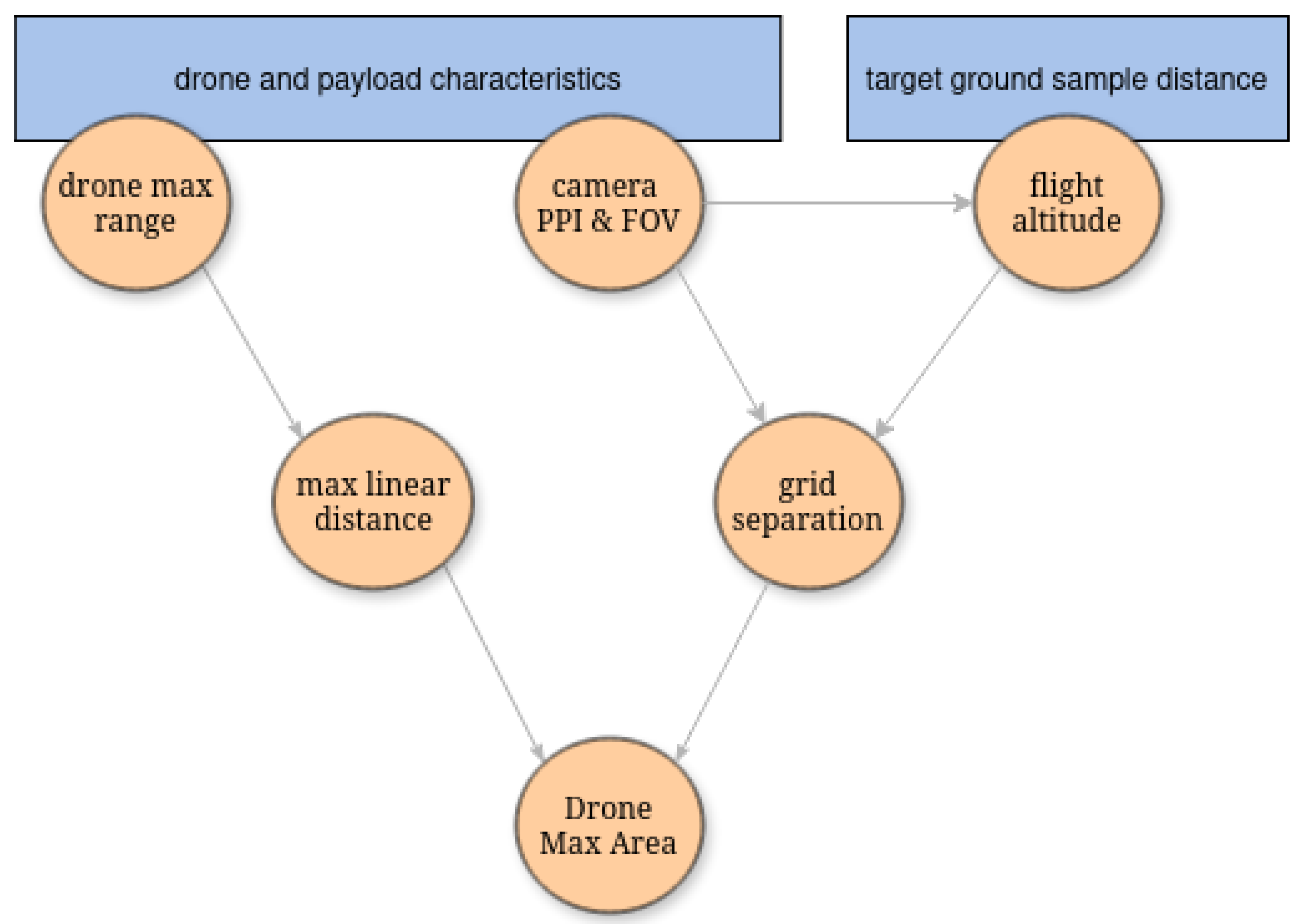
Figure 2.
Balanced split example.
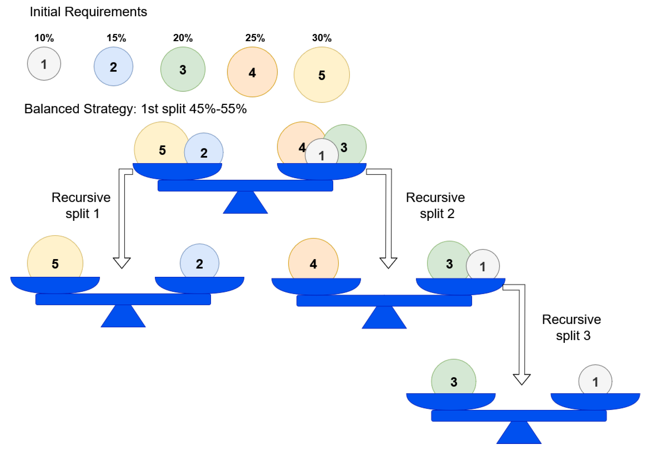
Figure 3.
An original and its rotated partitions by angles relative to the red segment.
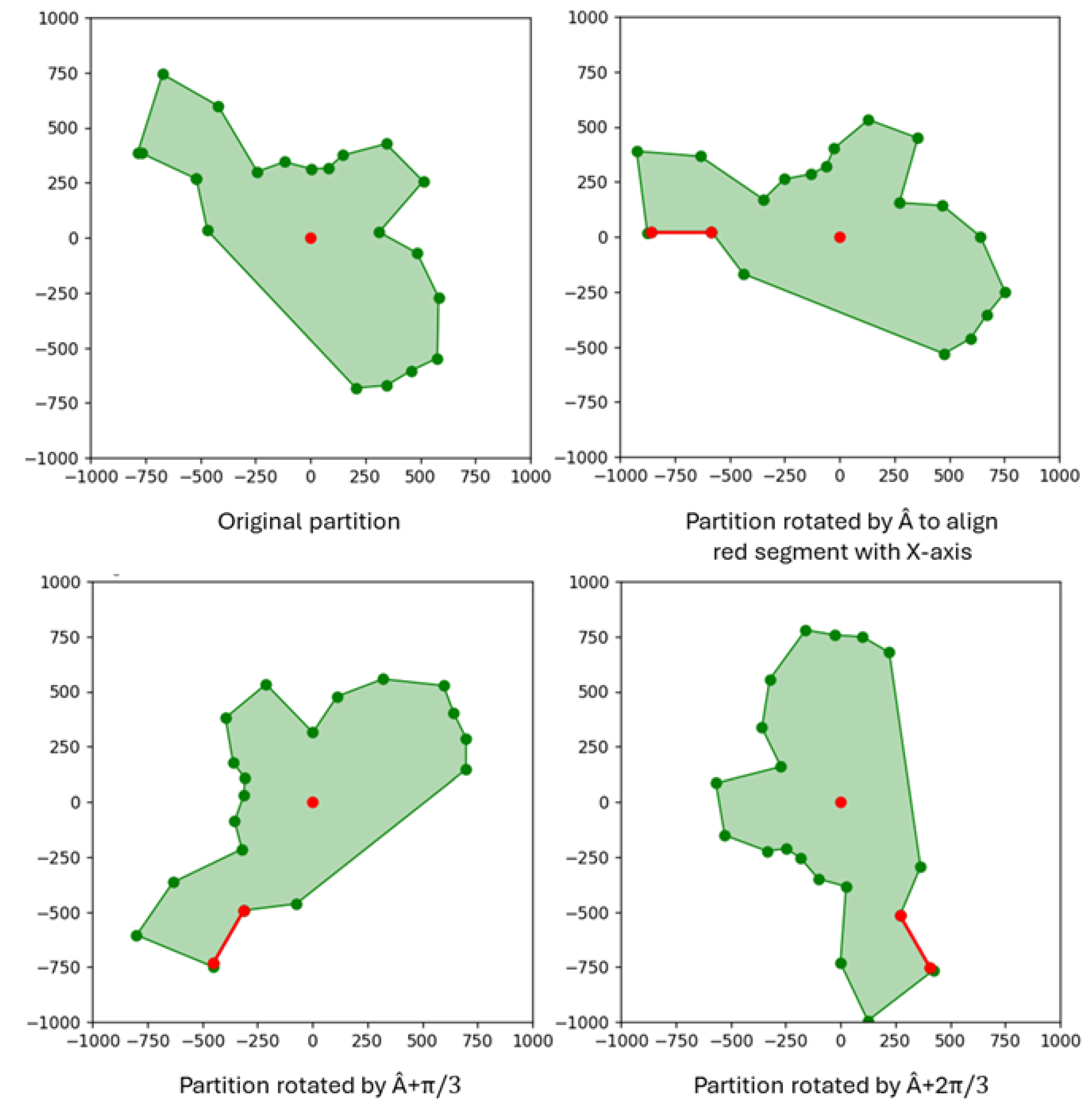
Figure 4.
Point grids generated for a partition with different rotations. Blue points are pass points, red points are no pass points, and yellow points are entry points belonging to the lowest line.
Figure 4.
Point grids generated for a partition with different rotations. Blue points are pass points, red points are no pass points, and yellow points are entry points belonging to the lowest line.
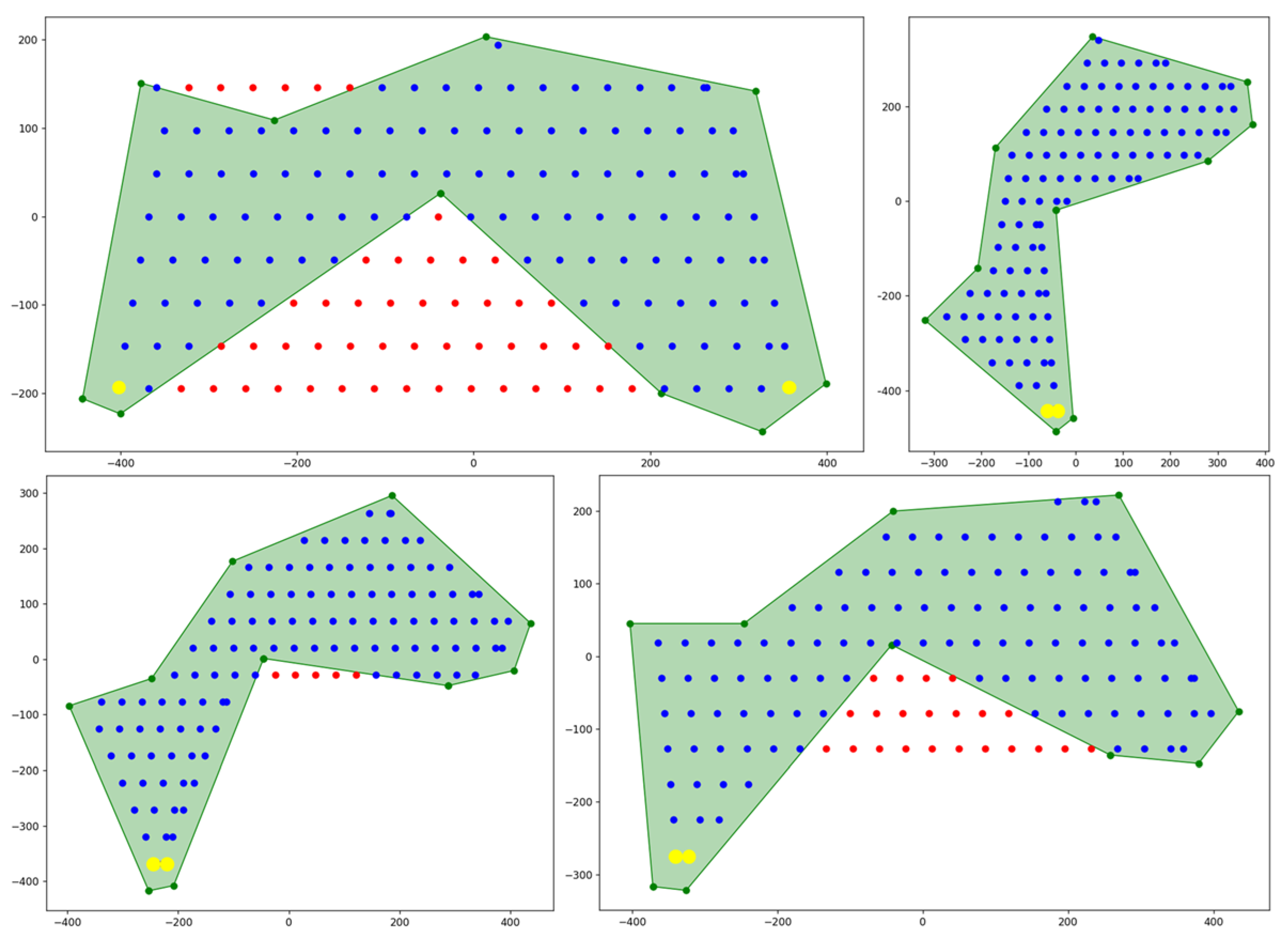
Figure 5.
Left: A graph connecting the polygon vertices. Right: the initial graph with two auxiliary nodes connected to the existing nodes. Blue circles represent nodes and black segments represent edges.
Figure 5.
Left: A graph connecting the polygon vertices. Right: the initial graph with two auxiliary nodes connected to the existing nodes. Blue circles represent nodes and black segments represent edges.
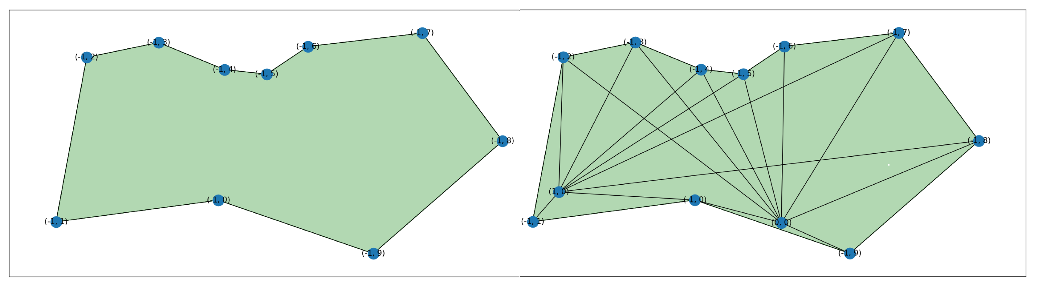
Figure 7.
Left: A graph constructed to avoid crossing any restricted areas. Right: Forward and backward paths generated to access a partition while avoiding restricted zones, using the graph on the left.
Figure 7.
Left: A graph constructed to avoid crossing any restricted areas. Right: Forward and backward paths generated to access a partition while avoiding restricted zones, using the graph on the left.
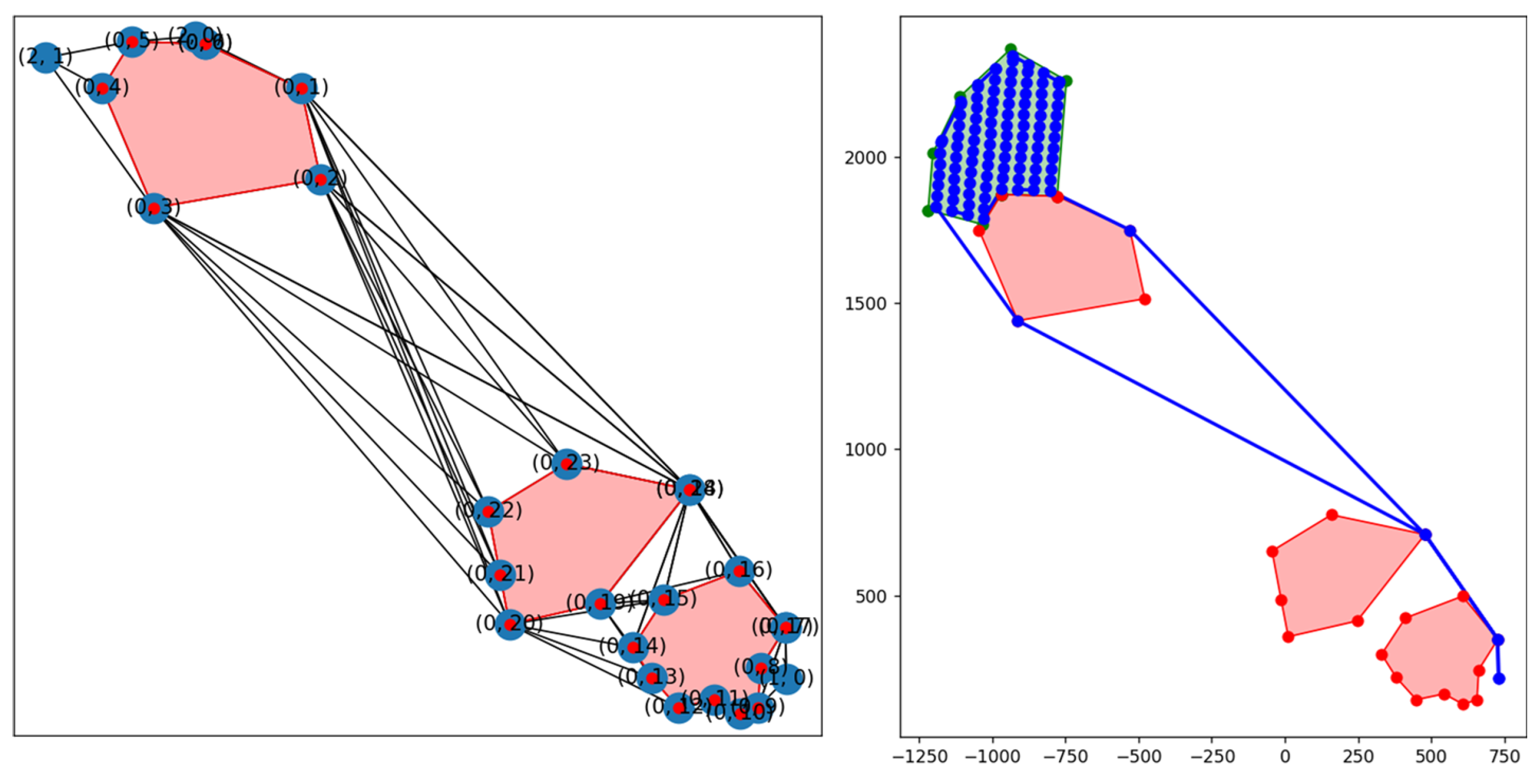
Figure 8.
Fyli area, in Greece, used in PANTHEON as the planning scenario of an earthquake disaster. On the right the polygon with the area of interest in grey and the initial location of the drones fleet.
Figure 8.
Fyli area, in Greece, used in PANTHEON as the planning scenario of an earthquake disaster. On the right the polygon with the area of interest in grey and the initial location of the drones fleet.
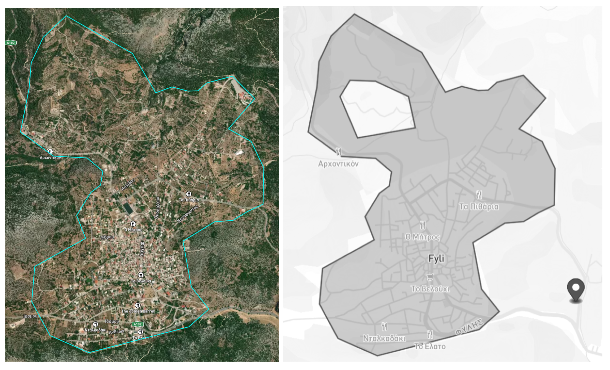
Figure 9.
Example of Fyli polygon partition using 3 different algorithms: PODE (left), NPD (middle) and PDAN (right). Original (top) and balanced (bottom).
Figure 9.
Example of Fyli polygon partition using 3 different algorithms: PODE (left), NPD (middle) and PDAN (right). Original (top) and balanced (bottom).
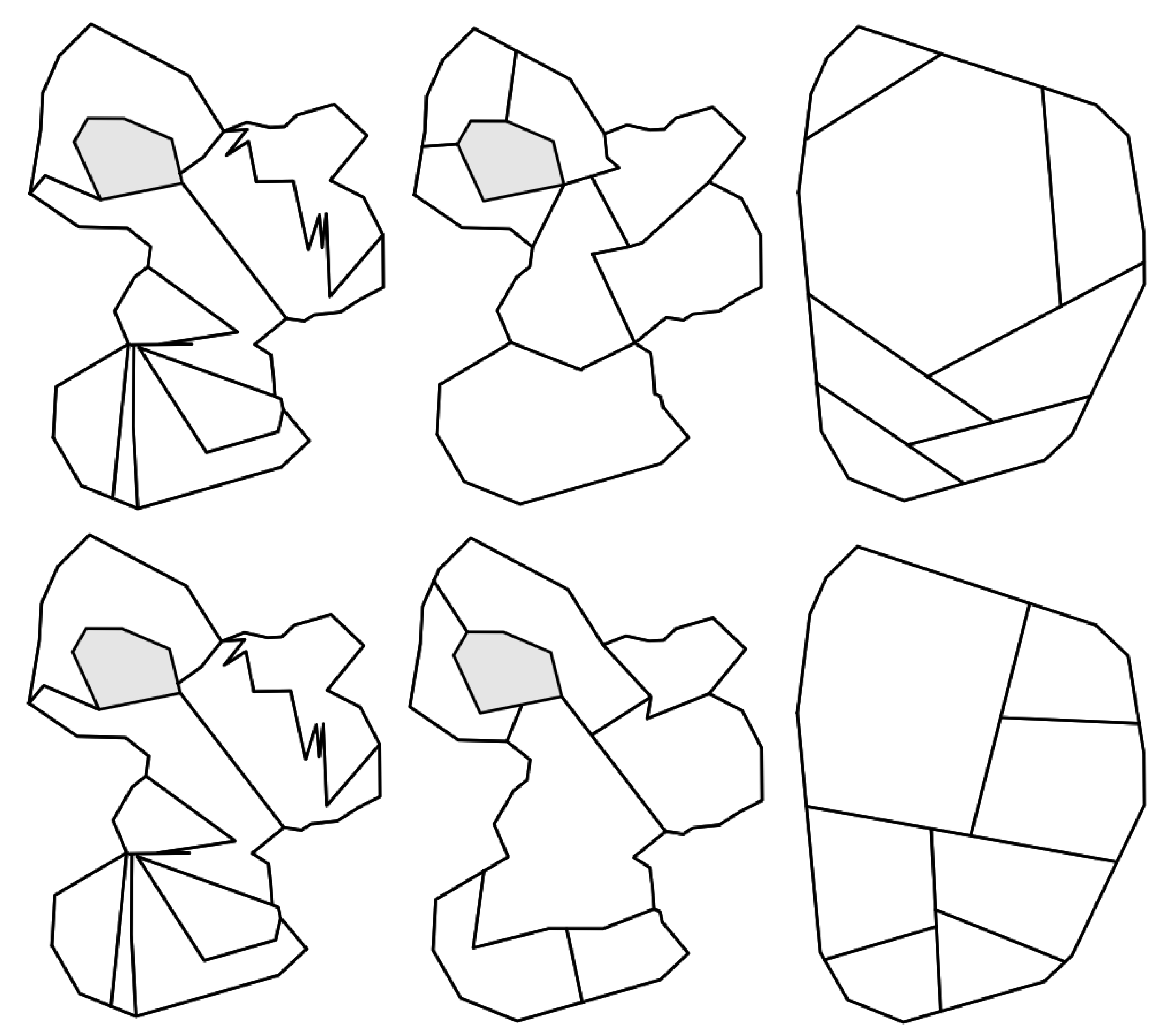
Figure 10.
Generated trajectories for the area of interest while avoiding no-fly zones. Left: Trajectories for the decomposed area using (non-balanced) NPD. Middle: A polygonal hole representing a no-fly zone, with avoidance paths. Right: Multiple external polygons as no-fly-zones, with corresponding avoidance trajectories.
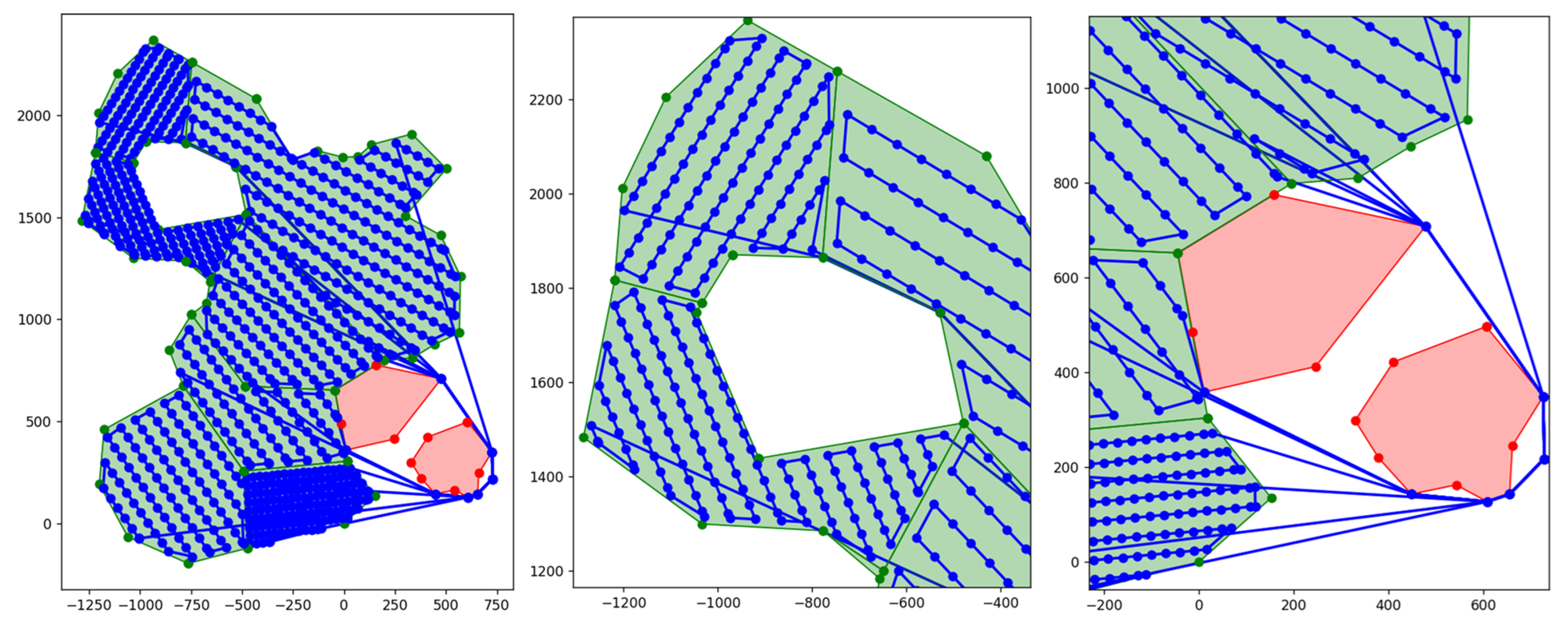
Figure 11.
Test areas for the comparison of our algorithm with EAMC[12].
Figure 11.
Test areas for the comparison of our algorithm with EAMC[12].
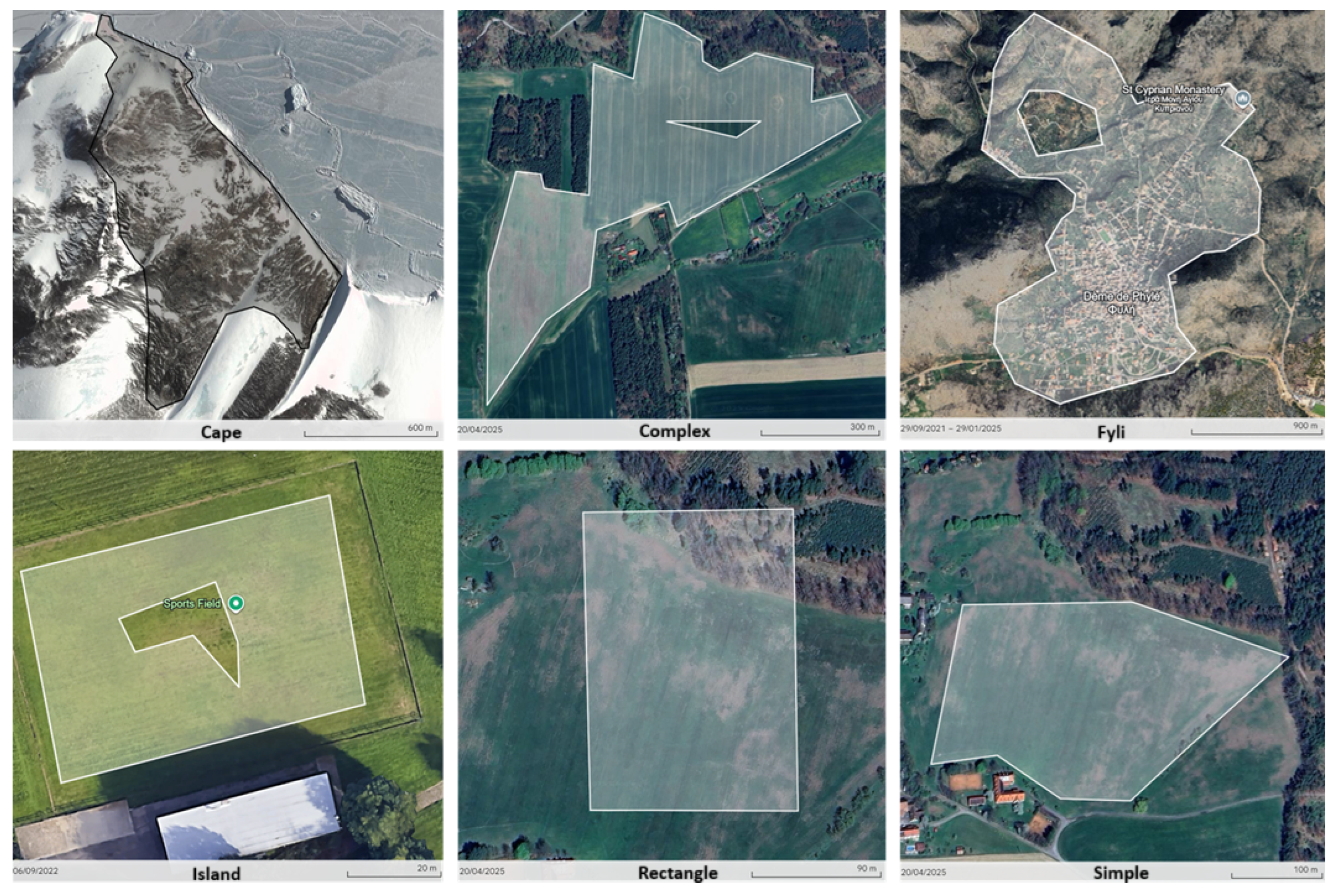
Figure 12.
Four examples of polygons dataset[35].
Figure 12.
Four examples of polygons dataset[35].
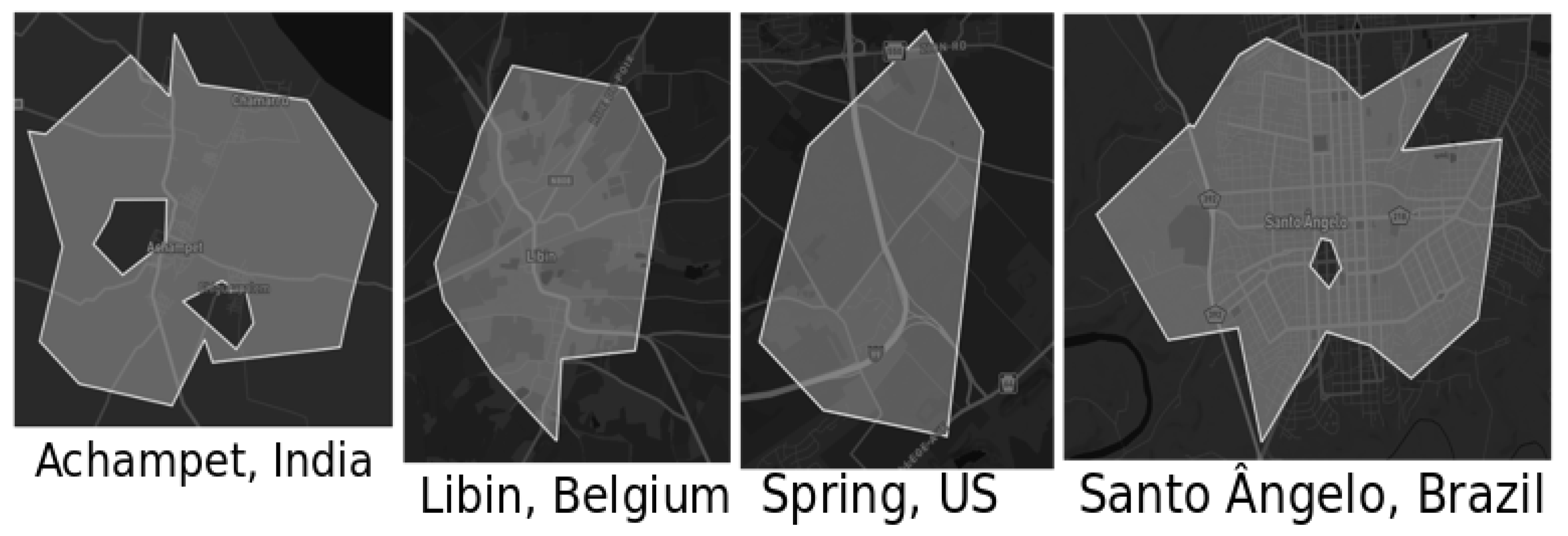
Figure 13.
Area of the polygons and capacities of the fleets.
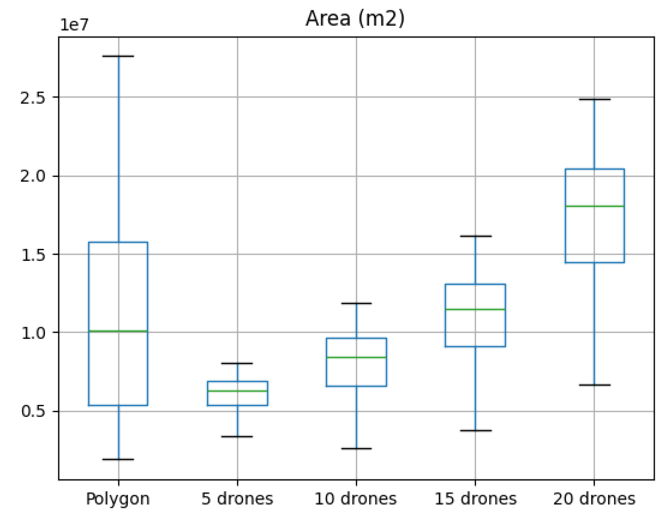
Figure 14.
Percent of the area covered, per algorithm and per fleet size.
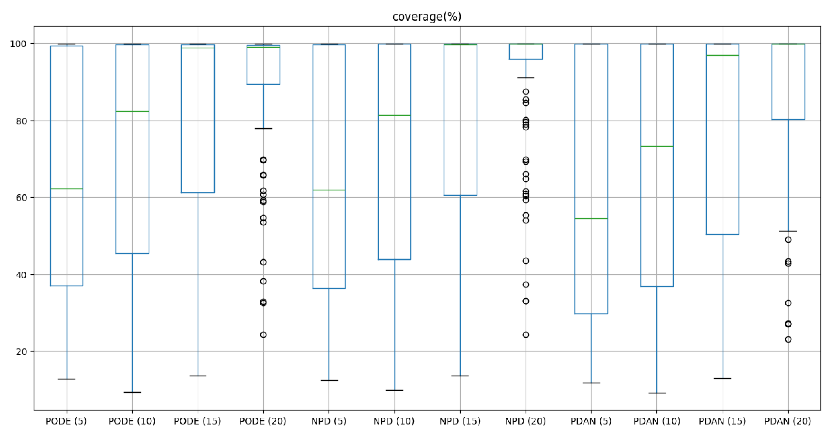
Figure 15.
Accuracy of the area assignment of each algorithm.
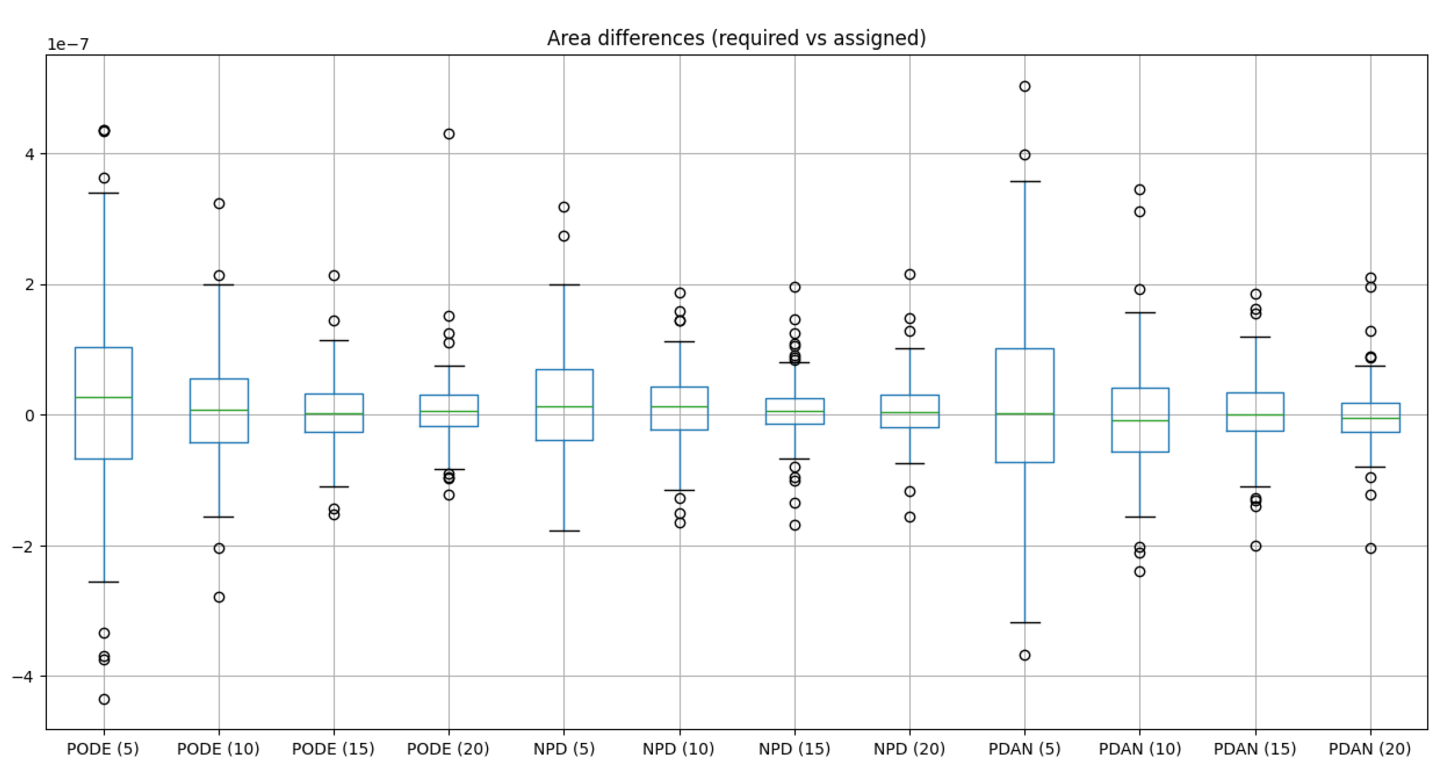
Figure 16.
Evaluating the balanced strategy: NPD in the left, PDAN in the right.
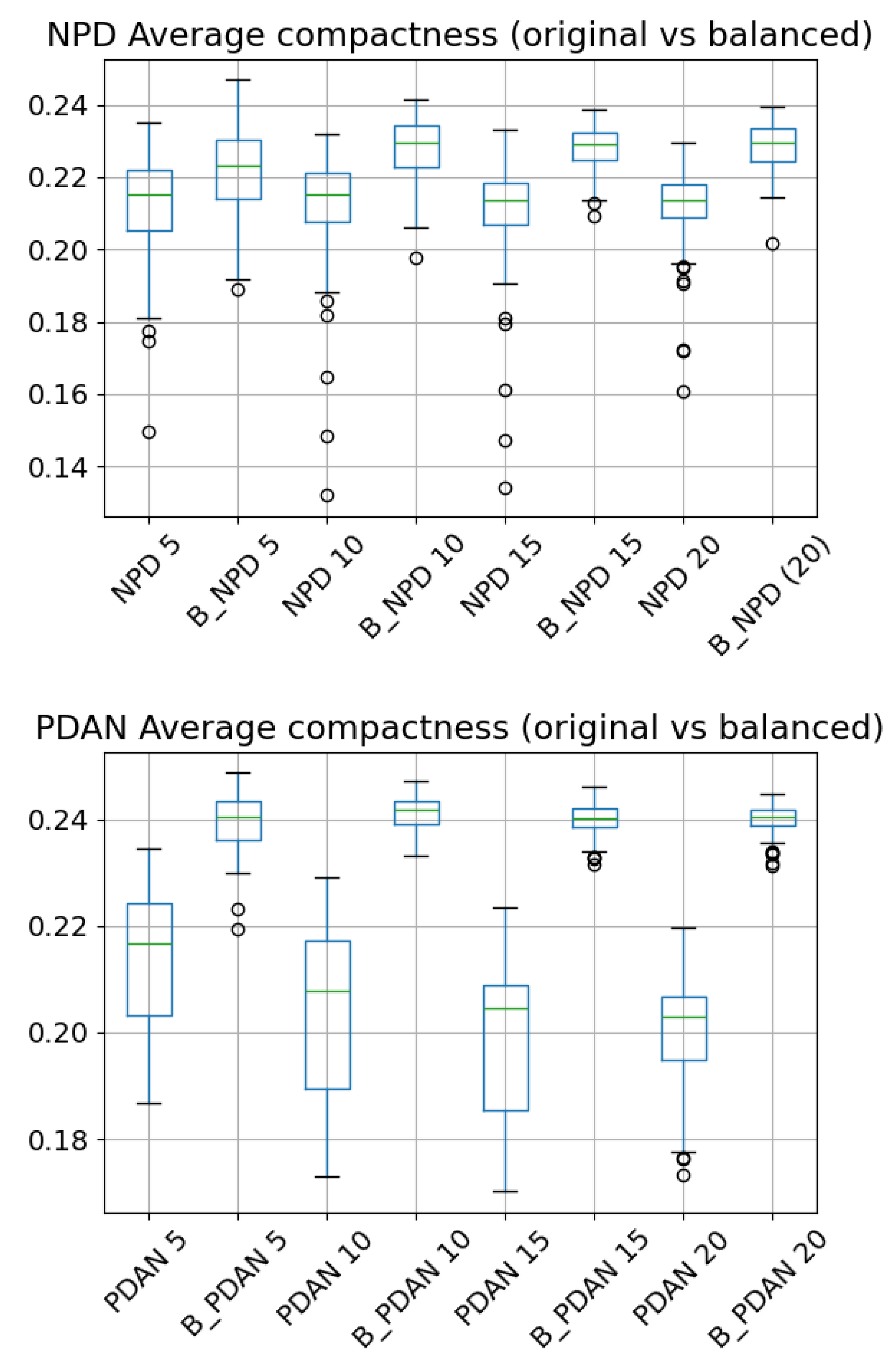
Figure 17.
Compactness per algorithm and per fleet size.
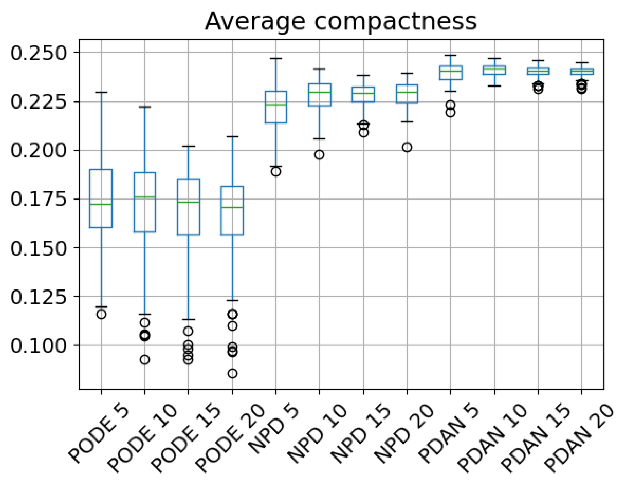
Figure 18.
Characterization of the generated trajectories.
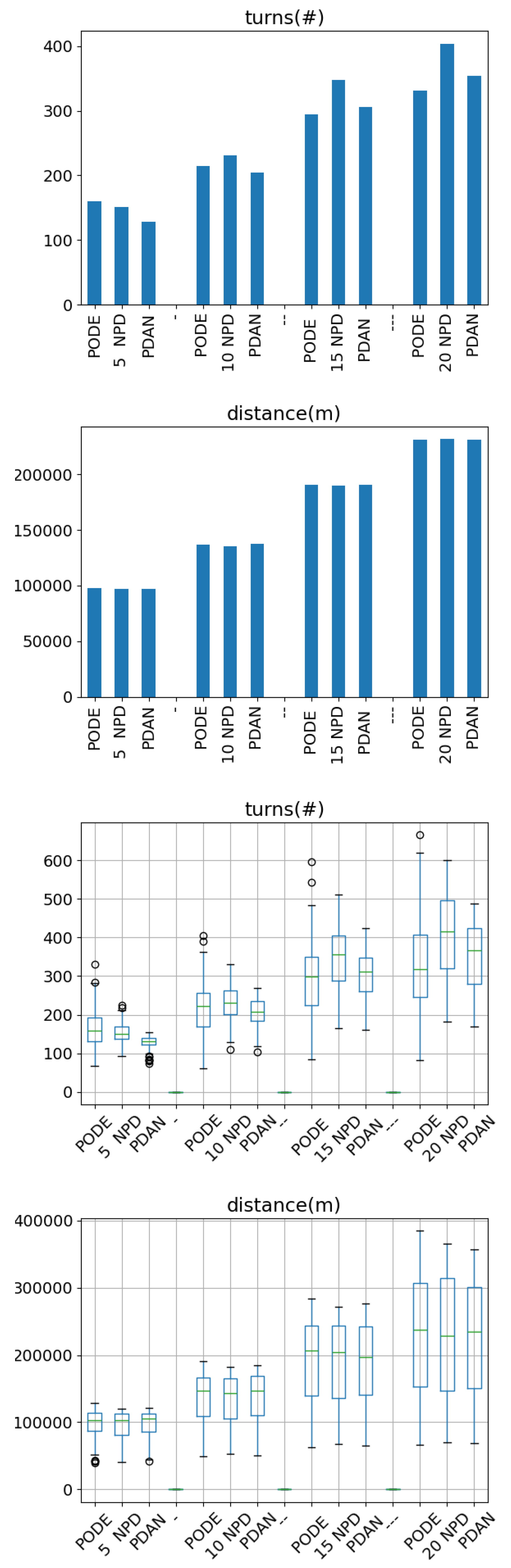
Figure 19.
Average total mission time (in flight minutes).
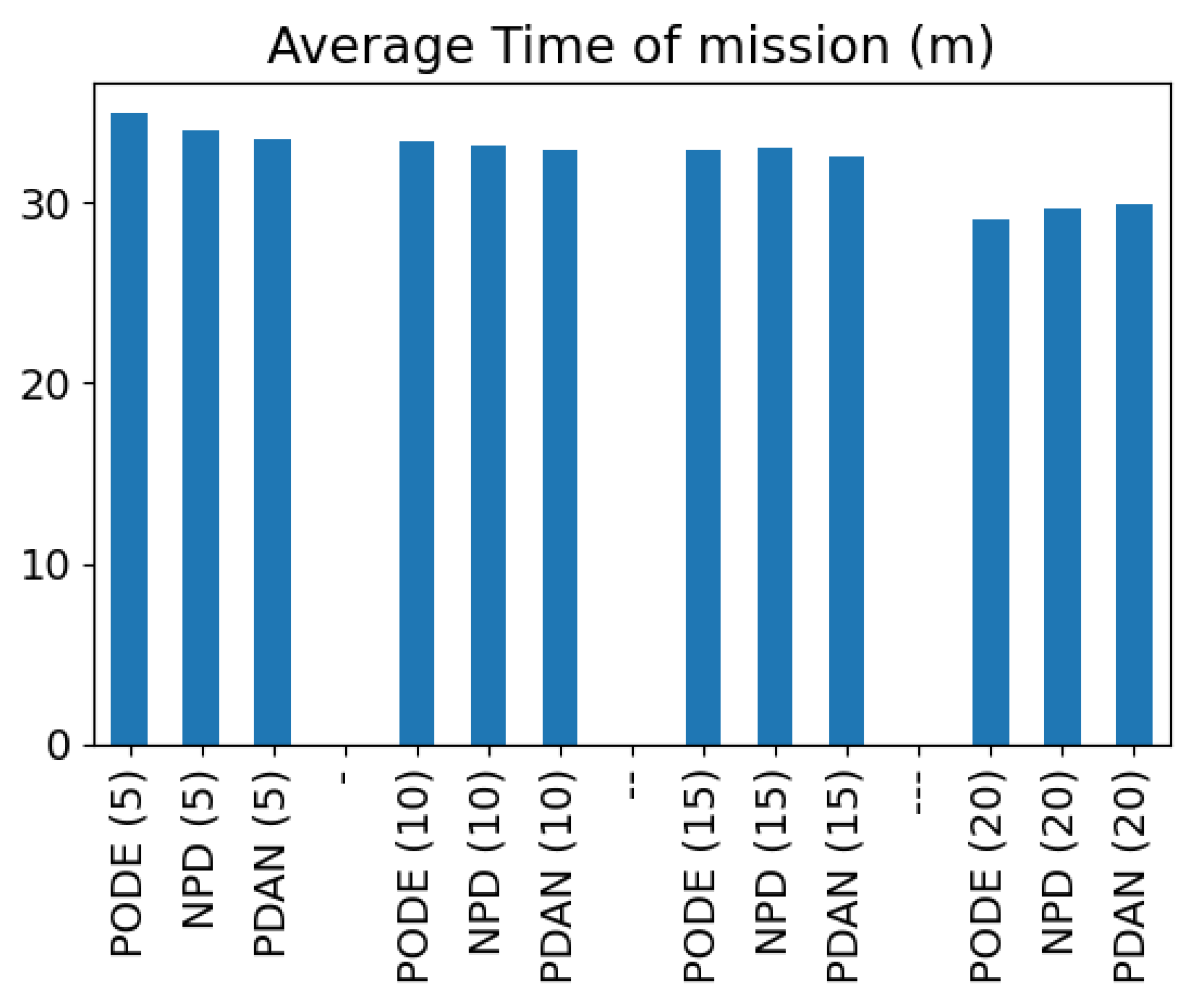
Figure 20.
Distribution of the flight time across different flight phases of the mission
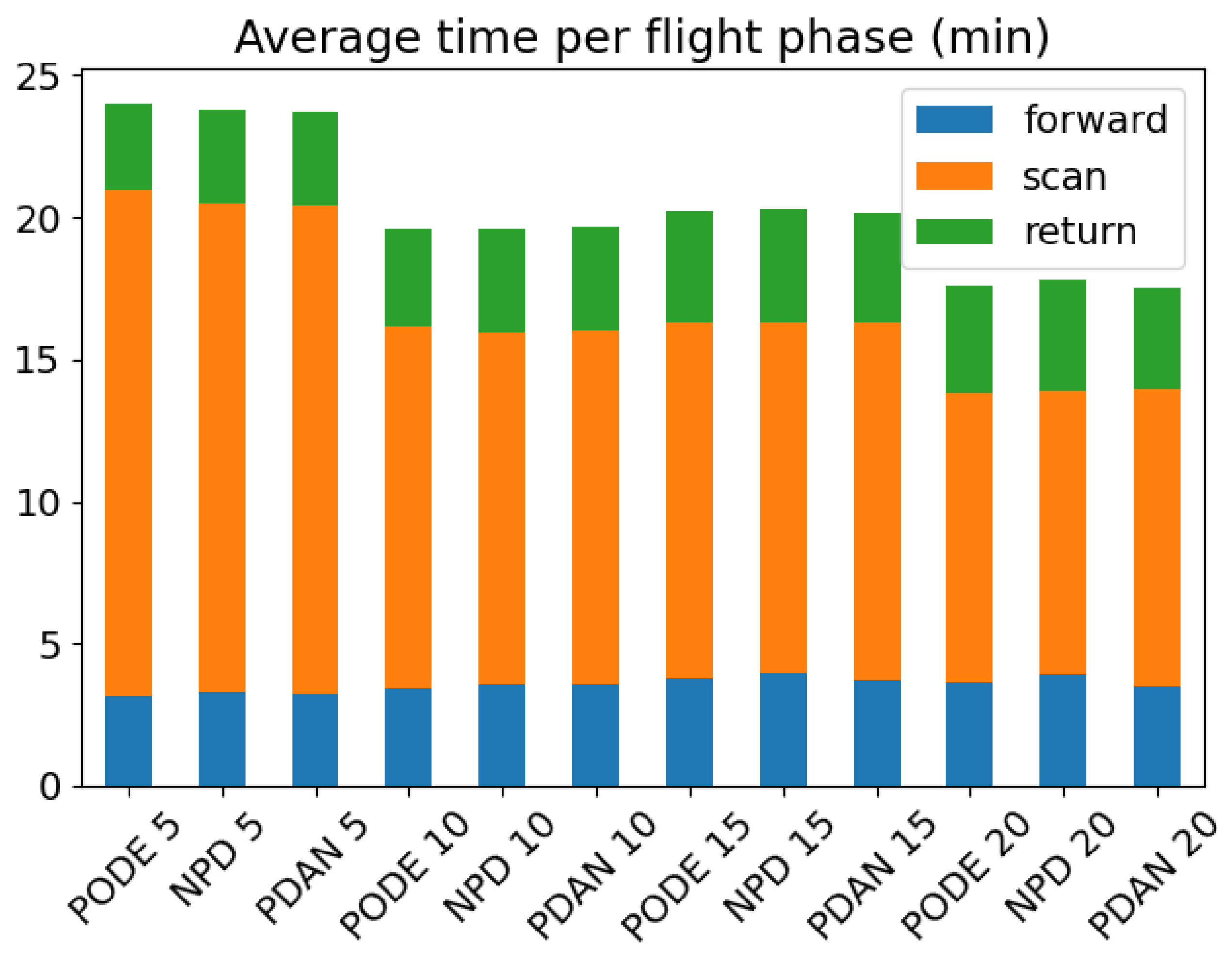
Figure 21.
Total mission time for scenarios under the fleet capabilities.
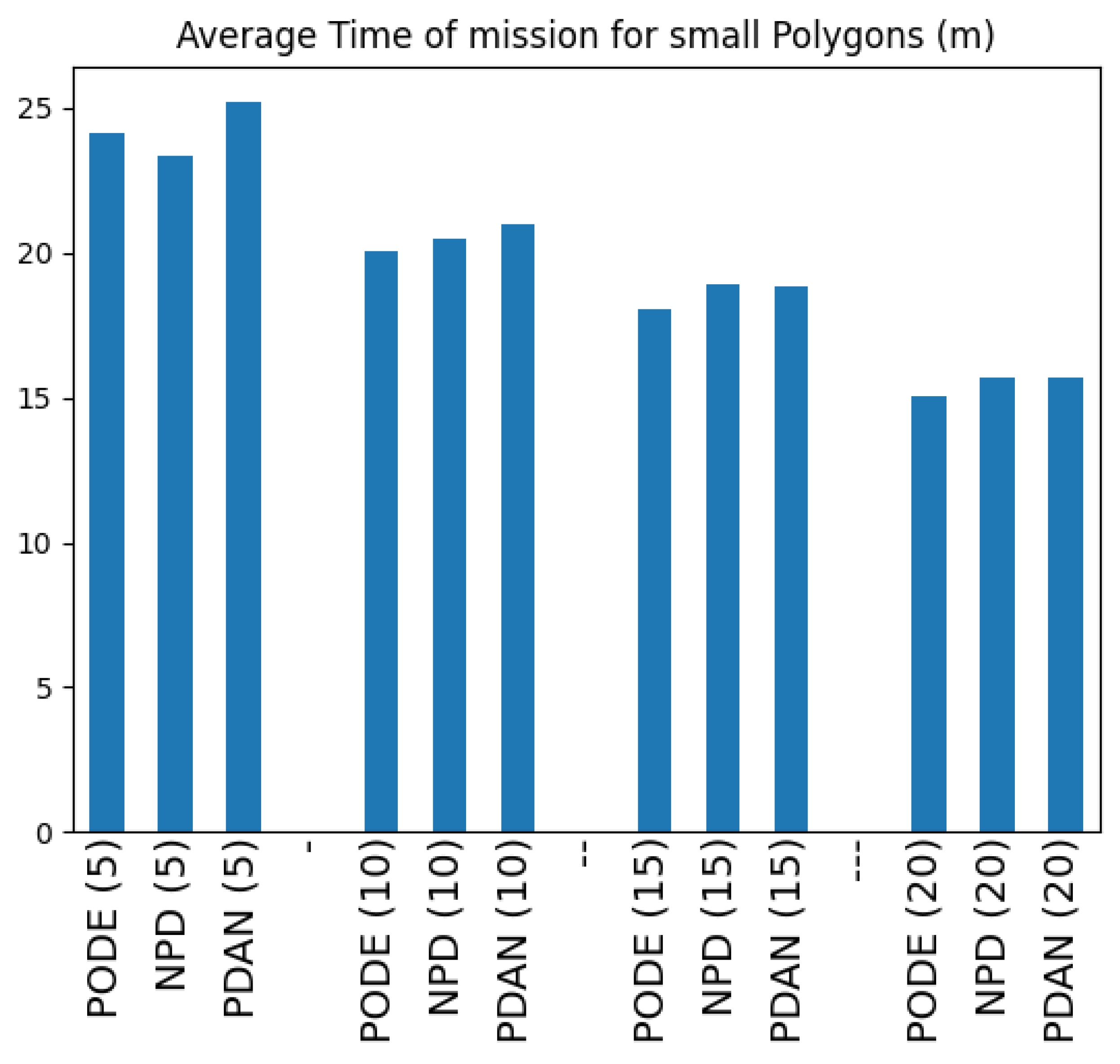
Figure 22.
Execution times: partition algorithm on the left and trajectory generation on the right.
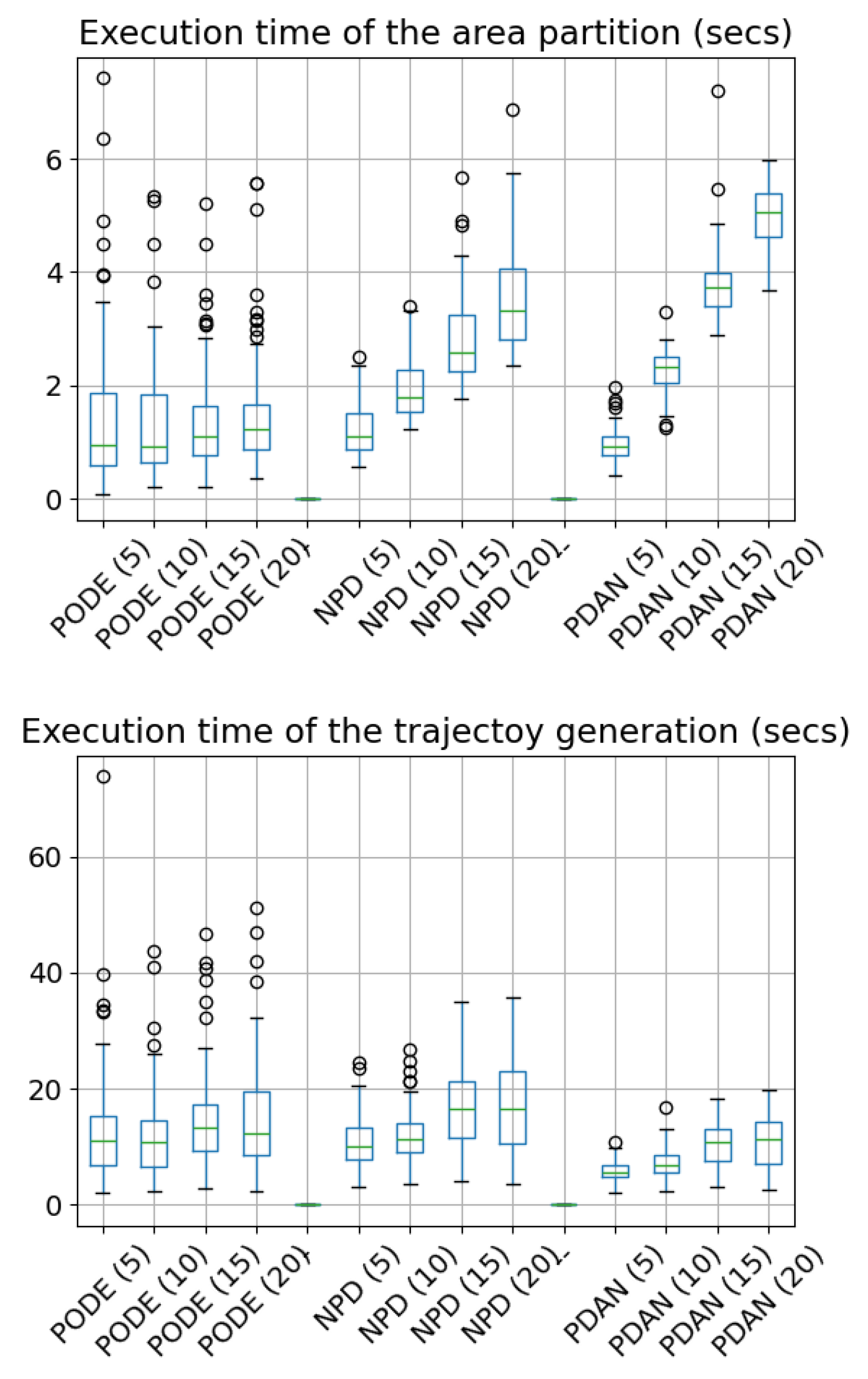
Table 1.
List of the seven drone models used in the Fyli test scenario. The values in italic are approximate.
Table 1.
List of the seven drone models used in the Fyli test scenario. The values in italic are approximate.
| Drone type | Maximum Flight Distance | Speed | Field of View H, V | Image resolution |
|---|---|---|---|---|
| (km) | (m/s) | (deg) | (pixels) | |
| Parrot Anafi AI | 22.5 | 14 | 64.6, 50.7 | 8000 x 6000 |
| DJI MINI 4 Pro | 18 | 11.3 | 69.7, 55.1 | 8064 x 6048 |
| DJI Phontom 4 Pro V2.0 | 18.63 | 10.35 | 71.5, 56.7 | 4864 x 3648 |
| DJI Air3 | 22.08 | 8 | 69.6, 55 | 8064 x 6048 |
| Skydio X2E Color | 20 | 8.3 | 67.7, 53.4 | 4056 x 3040 |
| Skydio X10 | 36 | 15 | 80.2, 64.6 | 8192 x 6144 |
| Yuneec H520E | 17.01 | 10.125 | 78.3, 62.8 | 4864 x 3648 |
Table 3.
Configuration of the scenarios
| Scenario name | cape | complex | fyli | island | rectangle | simple |
|---|---|---|---|---|---|---|
| Number of drones | 3 | 3 | 3 | 1 | 3 | 3 |
| Sweep distance | 35 m | 10 m | 55 m | 5 m | 8 m | 6 m |
| Lateral offset | 17.5 m | 5 m | 27.5 m | 2.5 m | 4 m | 3 m |
Table 4.
Algorithms specific configurations
| Algorithm | parameter | cape | complex | fyli | island | rectangle | simple |
|---|---|---|---|---|---|---|---|
| EAMC [12] | Minimum subpolygons per UAV | 4 | 3 | 3 | 1 | 1 | 1 |
| Rotations per cell | 4 | 3 | 3 | 5 | 3 | 5 | |
| Our 3-step method | Number of Steiner points | 70 | 45 | 35 | 35 | 70 | 35 |
Table 5.
Comparison of EAMC and our path planning algorithm for homogeneous fleet of drones
| Scenarios | EAMC | Our 3-step method | ||||||
|---|---|---|---|---|---|---|---|---|
| Number of turns | Flight distance | Flight time | Coverage | Number of turns | Flight distance | Flight time | Coverage | |
| (m) | (s) | (%) | (m) | (s) | (%) | |||
| cape | 162 | 35,633.6 | _ | _ | 97 | 35,254.87 | 871.42 | 100.0 |
| complex | 291 | 36,331.1 | _ | _ | 240 | 34,287.51 | 841.12 | 99.99 |
| fyli | 127 | 59,665.7 | _ | _ | 139 | 59,358.95 | 1,466.05 | 100.0 |
| island | 38 | 615.489 | _ | _ | 35 | 694.91 | 49.63 | 100.0 |
| rectangle | 54 | 4,373.02 | _ | _ | 54 | 4315.18 | 106.56 | 100.0 |
| simple | 103 | 10,580.8 | _ | _ | 138 | 9,981.93 | 245.32 | 99.99 |
Table 6.
Number of areas not covered by the fleet of drones for different sizes
| Fleet size | Not fully covered |
|---|---|
| 5 | 71 |
| 10 | 60 |
| 15 | 43 |
| 20 | 27 |
Disclaimer/Publisher’s Note: The statements, opinions and data contained in all publications are solely those of the individual author(s) and contributor(s) and not of MDPI and/or the editor(s). MDPI and/or the editor(s) disclaim responsibility for any injury to people or property resulting from any ideas, methods, instructions or products referred to in the content. |
© 2025 by the authors. Licensee MDPI, Basel, Switzerland. This article is an open access article distributed under the terms and conditions of the Creative Commons Attribution (CC BY) license (http://creativecommons.org/licenses/by/4.0/).
Copyright: This open access article is published under a Creative Commons CC BY 4.0 license, which permit the free download, distribution, and reuse, provided that the author and preprint are cited in any reuse.