Submitted:
14 October 2025
Posted:
15 October 2025
You are already at the latest version
Abstract
Hydrogen has the potential to become a key component of the global economy by reducing reliance on fossil fuel imports, enhancing energy independence, and mitigating climate change. Its future role depends on factors such as availability, cost competitiveness, supportive legislation, public-private collaboration, and advancements in catalyst development for electrolyzers and fuel cells. In this study, carbon-supported multimetallic MoFeNiP catalysts were developed as cost-effective, platinum-free electrocatalysts for the hydrogen evolution reaction (HER), via polymer-metal gel precursors and subsequent pyrolysis at different temperatures. The catalysts were evaluated in both acidic (0.5 M H₂SO₄) and alkaline (1 M KOH) media, revealing that C-MoFeNiP-1200 performed best in alkaline conditions, while C-MoFeNiP-1000 showed superior activity in acidic media. Electrochemical analyses confirmed favorable kinetics, efficient charge transfer, and good long-term stability. These results demonstrate that tuning pyrolysis temperature allows precise control over catalyst structure, surface properties, and performance, offering a sustainable and practical approach for designing efficient HER electrocatalysis.
Keywords:
transition metal phosphides
; carbon-based materials
; hydrogen evolution reaction
; electrocatalysis
1. Introduction
Hydrogen is widely recognized as a clean and sustainable energy carrier with the potential to play a key role in the transition towards low-carbon energy systems [1]. Among various hydrogen production methods, electrochemical water splitting offers a promising route for high/purity hydrogen generation, particularly when powered by renewable electricity [2]. However, the sluggish kinetics of the hydrogen evolution reaction (HER), especially in alkaline media, necessitate the development of efficient and durable electrocatalysts [3]. While noble metals such as platinum exhibit excellent HER activity, their high cost and scarcity limit large-scale deployment [4].
Carbon-based electrocatalysts for HER attract special attention due to their high electronic conductivity, high resistance to acidic and basic environments, and the possibility of obtaining them in different forms that increase surface area and exposure of active sites [5]. However, pristine carbon-based materials often do not have a sufficient number of active centers for HER, so their modification is necessary [5].
Modification of carbon materials with transition metals and their compounds has proven to be one of the effective approaches for achieving high electrocatalytic activity and stability [5,6]. The carbon matrix provides mechanical stability, a large specific surface area, and good electronic conductivity, while the metal particles form active sites for HER. The carbon matrix not only prevents the agglomeration of metal particles but also enables efficient charge transfer, which leads to the reduction of overpotentials and the improvement of HER kinetics. In addition to structural effects, the interaction between the carbon phase and metal particles leads to optimization of the electronic structure of the catalyst, which improves the hydrogen binding energy.
In the last decade, transition metal phosphides (TMPs) have emerged as a particularly interesting class of electrocatalytic materials for HER, which combine favorable electrical conductivity, tunable electronic structure, and good chemical stability [7]. Their high activity comes from the favorable electronic structure and the synergistic effect between metal and phosphorus. The presence of phosphorus changes the electronic structure around the metal centers, which optimizes the adsorption energy of hydrogen and accelerates the kinetics of the reaction. [8,9] In addition, multi-metallic TMP systems show pronounced synergistic effects between different metals, which enable fine-tuning of the electronic structure and optimization of activity [10,11]. Incorporation of TMP particles into the carbon matrix provides additional stability and electronic conductivity of the system, prevents the growth of particles during the synthesis, enables homogeneous distribution of active centers, and enables efficient HER over a wide pH range [12]. In this way, a combination of high electrical conductivity, stability, and optimized surface chemistry is achieved, which makes TMP/carbon composites a suitable basis for the development of efficient HER catalysts.
However, challenges remain in the precise control of composition and microstructure, as well as in the uniform distribution of elements and the avoidance of phase separation. An additional problem is the frequent use of cobalt, which, in accordance with the European classification of raw materials from 2023, is classified as a critical metal [13]. This is why in this paper, we focused on the combination of iron, nickel, and molybdenum. Iron and molybdenum are not classified as critical or strategic, while nickel is considered a strategic but not a critical element. This choice allows for a reduction in reliance on elements with high supply risk, while preserving electrocatalytic efficiency thanks to the complementary electronic and structural contributions of each metal.
Recently, carbon aerogels and xerogels have attracted growing attention due to their 3D porous architectures, ultralow density, high surface area, and excellent conductivity, which make them versatile platforms for applications in energy storage and conversion [14]. Our previous studies were focused on precursor gel comprising polyacrylonitrile (PAN) and the metal salts to obtain TMP nanofibers, either as pure phosphides [15] or as TMPs embedded in a carbon matrix [16,17,18]. In this work, the same precursor was applied to obtain non-fibrous, sponge-like composite resembling xerogels, providing a basis for future comparison of fibrous and non-fibrous morphologies and their influences on catalytic performance in HER.
Therefore, here, we present a systematic study on the synthesis and electrochemical performance of carbon-based electrocatalysts incorporating a MoFeNiP trimetallic phosphide (C-FeNiMoP), derived from PAN-based polymer-metal precursor gels. The dried gels were subjected to a three-step thermal processing: (i) stabilisation at 270 °C, (ii) pyrolysis in argon at three different temperatures (800 °C, 1000 °C, and 1200 °C) to investigate the influence of thermal treatment on the structural evolution and catalytic properties of the resulting materials, and (iii) treatment in a reducing atmosphere (Ar/H2) at 780 °C to finalize the formation of the active MoFeNiP phosphide phase. Particular emphasis was placed on elucidating the relationships between pyrolysis temperature, carbon structure, metal phosphide phase composition, and electrocatalytic activity towards HER. The catalysts were evaluated in both acidic and alkaline media to assess their bifunctional performance. This study not only deepens the understanding of C-MoFeNiP catalyst systems but also introduces a sustainable and scalable synthesis approach for designing efficient HER electrocatalysts suitable for diverse electrochemical environments.
2. Materials and Methods
2.1. Chemicals
Polyacrylonitrile (PAN, Sigma-Aldrich, Mw = 150 000 Da), iron (III) chloride nonahydrate (FeCl3×9H2O, Sigma-Aldrich), nickel (II) chloride hexahydrate (NiCl2×6H2O, Sigma-Aldrich) and molybdenum pentachloride (MoCl5, Sigma-Aldrich), dymethylformamide (DMF, Sigma-Aldrich), phosphoric acide (H3PO4, Sigma-Aldrich, 85% solution in water) were used for the prearation of the precursor gel. Nafion 117 containing solution (Sigma-Aldrich, 5% in a mixture of lower aliphatic alcohols and water), and Isopropyl alcohol (Merck, 99.7%), were used for preparation of catalytic ink. Sulfuric acid (Merck, 96% p.a.), and potassium hydroxide (Merck, p.a.), were used as electrolytes to investigate performance in acidic and alkaline media, respectively. All reagents were used without any further purification.
2.2. Preparation of the Catalysts
2.2.1. Preparation of the Precursor Gel
The precursor solution was prepared in three consecutive stages. First, the ceramic precursor components were mixed. Iron(III) chloride nonahydrate (2.73 g), nickel(II) chloride hexahydrate (2.39 g), and molybdenum pentachloride (2.70 g) were dissolved in 40 g of DMF (dimethylformamide) in an equimolar ratio and stirred magnetically for one hour. The resulting translucent emerald-green solution was then mixed with 0.96 mL of H₃PO₄ (phosphoric acid) for an additional hour, causing the color to change to a dark green. In the second stage, PAN (polyacrylonitrile) was dissolved in DMF at 85 °C for five hours under constant stirring to yield a viscous solution with a concentration of 16 wt.%. After cooling, the two solutions were blended in a 1:1 mass ratio in the third stage. The final mixture was thoroughly stirred, cast into petri dishes, and left to dry in a venting hood for 96 hours. During this drying period, hydrolysis by atmospheric moisture and solvent evaporation occurred, leading to the formation of a polymer-based gel that solidified into a bittle mass. The MoCl5 hydrolysis can be described by the following chemical reaction: MoCl5(s)+H2O(air mositurel)⟶MoOCl3(s)+2HCl(g). The hydrophobic polymer graft hinders the moisture penetration along with the entrapment of the formed HCl gas. In this way initiates the formation of pores inside the gel.
2.2.2. Preparation of the Carbon-Based Catalysts
The dried gels were milled into small granules and transferred to aluminum oxide crucibles. The granules were first stabilized in a lab oven at 270 °C. Following this stabilization, the material underwent heat treatment in a furnace under an argon flow, with the temperature sequentially increased to 800 °C, 1000 °C, and 1200 °C and treatment in a reducing atmosphere (Ar/H2) at 780 °C.
The resulting carbon-based material was then ground into a fine powder using an agate mortar for subsequent characterization.
2.2.3. Preparation of the Inks
Catalyst inks were prepared by dispersing 50 mg of the synthesized material in 1 mL of a solvent mixture consisting of isopropyl alcohol and deionized water in a 3:1 volume ratio, along with 10 μL of 5 wt% Nafion solution. The resulting suspension was ultrasonicated for 30 minutes to achieve a uniform dispersion. Before the ink deposition, the rotation disk glassy carbon electrode (GC-RDE, 5 mm diameter) was mechanically polished using alumina slurry, rinsed with deionized water, and dried. A total of 20 μL of the catalyst ink was drop-cast onto the cleaned GC-RDE surface in two successive layers (2 × 10 μL), allowing each layer to dry under ambient conditions. The resulting catalyst loading was approximately 1 mg / 5 mg cm-2.
2.3. Characterization
The phase composition of the final phosphide powders was determined by X-ray diffraction (XRD) analysis using a Cu Kα radiation source (Philips X'Pert Pro) operating at 40 kV and 50 mA. Diffraction patterns were recorded over a 2θ range of 10° to 120°. The morphology and porosity of the sample were examined using a scanning electron microscope (SEM, Zeiss Dual beam SEM/FIB Auriga compact) equipped with an energy-dispersive X-ray analyzer (EDX). The thermal degradation of the precursor samples was analyzed using differential thermogravimetric analysis (DTG) combined with thermogravimetric analysis (TG) (NETZSCH STA449F3 Jupiter). Measurements were performed at a heating rate of 10 °C·min⁻¹ up to 1200 °C in an Al₂O₃ crucible under an argon atmosphere. Before the analysis, the samples were processed under vacuum. Raman spectra were recorded by the Horiba Explora One Raman microscope.
The electrocatalytic performance toward the hydrogen evolution reaction was evaluated using a potentiostat VIONIC in a standard three-electrode configuration. A glassy carbon rotating disk electrode (RDE, 5 mm diameter) with drop-casted catalytic ink served as the working electrode, a platinum plate as the counter electrode, and an Ag/AgCl (3M KCl) electrode as the reference electrode. All potentials were converted to the reversible hydrogen electrode (RHE) scale using Equation 1:
Where is the measured potential using the Ag/AgCl (3 M KCl) reference electrode, and is the potential of Ag/AgCl (3 M KCl) versus the normal hydrogen electrode (NHE), i.e., 0.1976 V. Before each measurement, the GCE was mechanically cleaned and cycled in 0.5 M H2SO4. Linear sweep voltammetry (LSV) was performed at a scan rate of 1 mV s⁻¹ within the potential range of 0.5 to –1.0 V in both electrolytes, with rotation rates of 500 rpm in 1 M KOH and 1000 rpm in 0.5 M H₂SO₄. All electrochemical data were iR compensated. Tafel slopes were derived from the LSV curves by plotting overpotential vs. the logarithm of current density. Electrochemical impedance spectroscopy (EIS) was conducted in the frequency range of 100 kHz to 0.1 Hz at an overpotential of -0.485 V (1 M KOH) and -0.589 V (0.5 M H2SO4) to evaluate the charge transfer resistance. Cyclic voltammetry (CV) was performed in the non-faradaic region at different scan rates to estimate the double-layer capacitance (Cdl). Stability tests were conducted using chronoamperometry (CA) for 22 hours at -0.285 V in alkaline media and -0.229 V in acidic media.
3. Results and Discussion
3.1. Structural and Morphological Characterization
The most critical step in the preparation of MoFeNiP catalysts was found to be the heat treatment process. The heating program for the polymeric precursor sample was determined based on differential scanning calorimetry (DSC) and thermogravimetric analyses (TGA). Figure 1 shows the TG and DSC profiles of the polymeric sample, recorded under an argon atmosphere from 0 °C to 1200 °C, to observe the thermal behavior and the formation of the oxide phase of the future trimetallic MoFeNiP phase.
From a thermochemical perspective, the degradation of the precursor gel comprising of PAN/H₃PO₄ and the metal chlorides NiCl₂·6H₂O, FeCl₃·9H₂O, and MoCl₅ (hydrolize) can be divided into three main stages: i) Stabilization (pre-oxidation) of the polymer. This occurs between 23 °C and 233 °C. In this stage, a sharp exothermic peak at 233 °C is observed, which corresponds to oxidation reactions and the combustion of the polymer matrix [6,19]. At this stage, the loss of water from the ceramic precursors is also taking place. The process involves the simultaneous hydrolysis and decomposition of metal chloride precursors within a hydrophobic, non-water-soluble PAN-based polymer matrix. Critically, the polymer's structural integrity prevents the typical dissolution and collapse of the chloride salts in their own crystallization water, allowing the formed gel to retain its desired structure. Specifically, the thermal decomposition of FeCl3·9H2O and the rapid hydrolysis of MoCl5 both release HCl gas, forming species like Fe(OH)2Cl and molybdenum oxychlorides, respectively. This evolved HCl, along with water and other gases originating from the PAN stabilization, becomes entrapped within the matrix. These gaseous byproducts act as effective porogens, creating a robust micro/macroporous architecture in the final material. This phase is coupled with the thermal stabilization of the PAN polymer, initiating molecular cyclization and aromatization, simultaneously achieving the essential incorporation of phosphorus into the nascent carbonaceous network [17]. This stage is responsible for the major weight loss observed during the overall thermal degradation process. ii) Decomposition of metal chlorides and their previously formed crystallohydrates decomposition products. Occurring between 233 °C and 600 °C, this stage involves a slow exothermic process, visible as a gradual decline in the TG curve. It includes the stepwise dehydration of crystalline water from NiCl₂·6H₂O and Fe(OH)2Cl and possible FeCl₃·9H₂O leftovers, followed by further dehydrochlorination and dechlorination reactions [20]. iii) Final decomposition and phase formation. From 600 °C to 800 °C the final decomposition of the dehydrated metal chlorides and oxychlorides occurs, releasing Cl₂ gas. Beyond this temperature, only a negligible weight loss is detected also mostly originating from PAN final carbonisation. The remaining gradual decrease in mass is attributed to slow gradual dechlorination of metal chlorides leftovers and releasing of the entrapped gasess, leading to the formation of MoFeNi(PO₄)₂ within the graphitic carbon substrate network. This final product represents approximately 48 wt% of the original starting materials. Based on the results described above, three different temperatures 800 °C, 1000 °C, and 1200 °C were tested for the preparation of phosphate intermediates containing all three metals. Drawing from our previous experience, these intermediates were subsequently subjected to a reduction in a Ar/H2 atmosphere at 780 °C to form the final multimetal phosphides [18].
The structural analysis of the final MoFeNiP powdered electrocatalysts, sintered at three different temperatures, is presented in Figure 2.
All samples exhibited nearly identical X-ray diffraction (XRD) patterns, indicating the successful incorporation of all metallic elements into an orthorhombic and hexagonal crystal structure supported on a carbon matrix. According to database references, two distinct crystalline phases were identified: MoFeP, crystallizing in the orthorhombic system with space group Pnma (ICDD 04-001-4637; a = 5.922 Å, b = 3.663 Å, c = 6.790 Å), characterized by prominent reflections at 2θ ≈ 39.6° (112), 42.0° (211), 43.7° (103), and 50.4° (020) and NiMoP, crystallizing in the hexagonal system with space group P6̅2m (ICDD 04-008-7245; a = b = 5.861 Å, c = 3.704 Å), with the most intense diffraction peaks observed at 2θ ≈ 39.2° (111), 43.1° (201), and 47.4° (210). In addition, graphitic carbon with a hexagonal structure belonging to space group P6₃/mmc (ICDD 04-007-8496; a = b = 2.430 Å, c = 6.940 Å). The most intense peaks corresponding to this phase were observed at 2θ ≈ 25.6° and a weaker reflection at 45°, attributed to the (002) and (101) planes, respectively. In summary, although the fundamental crystal lattice remains unchanged, increasing the sintering temperature leads to changes in peak intensities in the 2θ range of 40–43°, along with more pronounced diffraction signals. This variation in the C-MoFeNiP pattern can be attributed to improved crystallization at higher temperatures.
The structural nature and disorder level of the carbon component were investigated using Raman spectroscopy (Figure 3).
The Raman spectra exhibit two characteristic bands indicative of graphitic carbon (Figure 3): the G band at 1586 cm⁻¹, corresponding to the in-plane stretching vibration of sp²-hybridized C–C bonds in an ordered graphitic lattice, and the D band at 1340 cm⁻¹, which arises from the breathing modes of sp² carbon rings and is activated by structural disorder or defects within the carbon matrix. The intensity ratio ID/IG, which reflects the degree of disorder and defect density in the graphitic structure, was found to be approximately 1 across all samples, with only minor variations observed. This consistent ratio suggests the formation of a similar hexagonal graphitic carbon phase in all samples, independent of the sintering temperature applied. Furthermore, the ID/IG ratio close to 1 indicates a high degree of structural disorder, characterized by a significant presence of defects, vacancies, grain boundaries, edge sites, and possible interlayer misalignment within the graphitic domains. This disorder may also point to the presence of partially reduced graphene-like structures, or alternatively, indicate that the sintering temperature was insufficient to promote full graphitization into a more ordered carbon structure. Notably, such disordered carbon materials with abundant edge sites and structural defects are advantageous for electrocatalytic applications, as these features contribute to an increased number of electrochemically active sites, thereby enhancing catalytic performance.
The morphology and elemental distribution of all synthesized samples were examined using SEM coupled with EDX analysis (Figure 4). The SEM images reveal a uniform dispersion of particles both within and on the surface of the carbon matrix, exhibiting a broad particle size distribution ranging from 30 to 600 nm (Figure 4 a,b).
This size range remained relatively consistent across all sintering temperatures, indicating good thermal stability of the particle morphology. A slight deviation was observed in the sample sintered at 800 °C (C-MoFeNiP-800), where a reduced number of particles were detected on the carbon surface, suggesting possible changes in particle matrix interactions at elevated temperatures. Notably, increasing the sintering temperature led to a subtle morphological evolution from predominantly spherical to slightly ellipsoidal particle shapes (Figure 5).
This transformation is attributed to enhanced atomic mobility and anisotropic growth mechanisms at higher temperatures phenomena that are well-established in nanomaterial systems. Furthermore, elevated thermal energy drives the improved interdiffusion and mixing of metallic species within the phosphide phase, resulting in the development of more homogeneous and structurally integrated metal phosphide domains [21].
EDX mapping analysis confirmed the preferential localization of metal elements (Mo, Ni, and Fe) along with phosphorus at the positions corresponding to the observed particles in the SEM overview. This spatial correlation indicates the successful incorporation of Mo, Ni, and Fe into the phosphide phase. Furthermore, the carbon matrix was identified as a supportive framework for the formation and stabilization of the trimetallic phosphide micro/nanoparticles, serving as both a dispersing medium and a structural support. Table 1 summarized the elemental composition of the prepared sample.
It is evident a little lower content of Mo given the molar ratio of the input salts which was equimolar. This observation may be attributed to the intrinsic properties of molybdenum, which has a significantly higher melting point and lower diffusivity compared to Fe and Ni. At the given sintering temperatures, these factors can hinder the efficient diffusion and incorporation of Mo into the phosphide structure. Additionally, if Mo is more deeply embedded within the carbon matrix, the carbon may attenuate or absorb part of the emitted X-rays during EDX analysis, leading to an underestimation of Mo content. This effect is particularly relevant when analyzing heavier elements, such as Mo, in a light-element matrix like carbon.
3.2. Electrochemical Characterization
The electrocatalytic properties of C-MoFeNiP materials synthesised at different pyrolysis temperatures were systematically investigated for HER in both alkaline (Figure 6 and Table 2) and acidic Figure 7 and Table 3) media. In alkaline conditions, catalytic performance improved with increasing pyrolysis temperature, with C-MoFeNiP-1200 exhibiting the highest HER activity (η₁₀ = 321 mV). In contrast, in acidic media, optimal performance was observed for C-MoFeNiP-1000 (η₁₀ = 228 mV). The difference in optimal catalysts between alkaline and acidic environments is consistent with previous reports, but its mechanistic origin remains not fully understood [11].
Further electrochemical characterization revealed that the best-performing catalysts also exhibited the most favorable kinetic parameters, including the lowest Tafel slopes and highest charge transfer coefficient (α), indicating faster reaction kinetics, as well as the smallest charge transfere resistence (Rct), reflecting more efficient charge transfer at the catalyst–electrolyte interface.
A closer examination of the Tafel slopes provides additional mechanistic insight. Depending on the synthesis temperature, the Tafel slopes decreased with increasing pyrolysis temperature from around 120 mV dec⁻¹ to 93 mV dec⁻¹ (C-MoFeNiP-1200 in alkaline media) and 98 mV dec⁻¹ (C-MoFeNiP-1000 in acid), indicating that the appropriate choice of temperature can improve the Volmer step and thereby enhance overall HER kinetics [22].
EIS further elucidated charge-transfer behavior. In both alkaline media and acidic media, Nyquist plots fitted with an equivalent circuit comprising solution resistance (Rs), Rct, and a constant phase element (CPE) revealed similar Rs values (between 4-5 Ω) for all catalysts.
In alkaline media, Rct increased with decreasing pyrolysis temperature (5.3 Ω, 9.6 Ω, and 13.7 Ω for C-MoFeNiP- 1200, -1000, and -800, respectively), indicating more efficient charge transfer for higher temperature samples, while in acidic media, Rct followed a different trend (4.5 Ω, 3.6 Ω, and 7.6 Ω for C-MoFeNiP- 1200, -1000, and -800, respectively) with the lowest Rct for C-MoFeNiP-1000 correlating with its superior HER activity.
Furthermore, capacitance analysis provided insight into the nature of active sites in C-MoFeNiP. While the Cdl, determined from non-faradaic CV measurements, showed no correlation with HER activity, the effective capacitance (Ceff), extracted from EIS measurements under faradaic conditions, demonstrated a clear correlation. This observation aligns with recent reports highlighting that Cdl often does not reflect the true number of active sites, as it includes contributions from both inactive and active regions of the catalyst [22], while Ceff more reliably reflects the sites involved in the reaction [23] These results suggest that the carbon primarily serves as a conductive and stable support, while the actual HER activity originates from metallic phosphide phases [5].
Differences in HER performance among the catalysts obtained at different pyrolysis temperatures can be attributed to structural and compositional changes. XRD and EDX analyses revealed that the increasing pyrolysis temperature promotes both the improved crystallization and interdiffusion and mixing of metallic species within the phosphide phase of C-MoFeNiP (Figure 2). Although the Raman spectra did not reveal any significant changes in the degree of disorder within the carbon matrix, the increase in temperature clearly indicates enhanced crystallinity of phoshide phases (Figure 2) and notable alterations in particle morphology, particularly at 1200 °C (Figure 5). These results indicate that the observed variations in HER activity of C-MoFeNiP obtained at different temperatures are mainly governed by the crystalline phase and composition of the metal phosphides.
Chronoamperometric stability tests of C-MoFeNiP-1200 in alkaline media revealed an increase in current density during the initial 10 h, followed by steady-state behavior. In acidic media, the chronoamperometric test revealed a stable current response over time, indicating good electrochemical stability of C-MoFeNiP-1000 (Figure 8).
However, the observed current densities were significanlty lower than in alkaline media, likely due to gas bubble accumulation on the electrode surface despite forced convection (1000 rpm). SEM analysis at lower magnification did not reveal any significant morphological changes compared to the material prior to the stability test (Figure 9a,c), indicating overall structural integrity. However, high-resolution imaging clearly shows surface disruption in both samples. In particular, under acidic conditions, leaching of the carbon matrix was observed, leading to the exposure of embedded phosphide particles. A comparable effect was noted under alkaline conditions, where increased porosity of the carbon matrix was evident (Figure 9b,d).
Overall, the combined electrochemical analyses demonstrate that the HER performance of C-MoFeNiP catalysts is strongly influenced by pyrolysis temperature, which governs the crystalline phase and composition of the metal phosphides, the kinetics of the Volmer step, and the charge-transfer properties at the catalyst-electrolyte interface.
The C-MoFeNiP electrocatalyst, being a multimetallic phosphide system, exhibits distinct electrocatalytic behavior in acidic and alkaline media due to differences in HER mechanisms, adsorption properties, and the influence of pH on active site functionality.
It has been previously reported that TMP-based catalysts exhibit different behaviors in alkaline and acidic environments during HER. In an alkaline medium, where the HER is generally the slowest step due to the water dissociation step, P can dissolve, leaving the remaining metal to transform into hydroxides and oxides. Wei et al. [24] reported that Mo oxides formed on MoFeNiP enhance HER activity, while Zhang et al. [25] emphasised that this increase in activity is apparent because the formed metal oxides drastically increase the ECSA, and when activity is compared by ECSA instead of geometric surface area, a decrease in activity is observed rather than an increase. To confirm this, more detailed characterisation before and after the stability test is needed to further optimise HER performance of C-MoFeNiP in alkaline media.
Regarding the behaviour of TMP in acidic media, generally with a fast Vomer step, it has already been shown that both metal and P dissolve, but the dissolution is proportional, so the activity is maintained. However, the retention of H₂ bubbles creates a resistive barrier, which significantly reduces the activity of the catalyst. Addressing this issue will require optimizing the hydrophilic and hydrophobic properties of C-MoFeNiP to facilitate bubble release [11].
4. Conclusions
This work represents an extension of our prevous studies, where polyacrylonitrile (PAN)-based precursor gel containing metal chlorides were used to obtain transition metal phosphide (TMP) nanofibers. In the present study, the same precursor system was applied to syntesize non-fibrous, structures.
Through controlled pyrolysis at different temperatures, the PAN-polymer based precursor was successfully converted into carbon-based MoFeNiP catalysts (C-MoFeNi-x, x = 800, 1000, and 1200 °C).
The obtained catalysts were systematically evaluated for their HER performance in both alkaline and acidic media. The results revealed that catalyst performance strongly depends on the pyrolysis temperature. In alkaline media, C-MoFeNiP-1200 exhibited the best performance, while in acidic media, C-MoFeNiP-1000 was the most active. Electrochemical analyses demonstrated that the most active catalysts also possessed the most favorable kinetic parameters, characterized by lower Tafel slopes, higher charge transfer coefficient values, and smaller charge-transfer resistance.
Capacitance and impedance studies further confirmed that the carbon framework primarily serves as a conductive support, while the metallic phosphide phases act as the true active centers for HER.
Structural characterization confirmed that performance variations of catalysts obtained at different temperatures originate from differences in the crystalline phase and composition of the metal phosphides. Higher temperatures promote improved crystallinity, interdiffusion and mixing of metallic species within the phosphide phase, and the formation of more homogeneous and structurally integrated metal phosphide domains, which together govern the enhanced catalytic performance.
EIS and stability measurements revealed efficient and durable charge transfer at the catalyst–electrolyte interface, with C-MoFeNiP-1200 showing excellent stability in alkaline media and C-MoFeNiP-1000 maintaining stable activity in acidic conditions.
SEM analysis after the stability test revealed no significant morphology degradation, confirming the overall structural integrity of the catalysts. However, localized surface changes were observed under different pH conditions. In alkaline media, increased porosity of the carbon matrix was evident, which may have caused the observed activity enhancement during the stability test. In contrast, in acidic media, leaching of the carbon matrix and exposure of embedded phosphide particles were observed, yet the catalysts maintained stable activity during prolonged measurement. However, significantly lower current density in acidic media were observed, most likely due to gas bubble accumulation on the surface. This indicates limited wettability and suggests the need for further optimization of the catalyst surface.
Overall, this study demonstrates a feasible and scalable approach for synthesizing efficient and durable non-fibrous C-MoFeNiP catalysts derived from PAN-based polymer precursors. The results confirm that control of pyrolysis temperature plays an important role in tuning the structural, surface, and electrochemical properties of the resulting materials. The carbon matrix ensures electronic conductivity and mechanical integrity, while the embedded MoFeNiP phases are responsible for the catalytic activity. The catalysts exhibit high stability and HER performance in both acidic and alkaline conditions, confirming their pH-universal applicability. However, further optimization of surface wettability, particularly for operating C-MoFeNiP catalysts under acidic media, is needed to minimize gas bubble accumulation and enhance overall HER performance.
In addition, this study provides a basis for future work focused on comparing the catalytic behavior of fibrous and non-fibrous-based materials, contributing to a deeper understanding morpholgy- HER performance relationships in polymer-derived HER catalysts.
Author Contributions
Conceptualization, T.M, A.G. and MS.; methodology, I.S. and E.M; software, O.M..; validation, T.M. and A.G; formal analysis, I.S. and E.M.; investigation, T.M, A.G and M.S.; resources, M.S.; data curation, O.M.; writing—original draft preparation, T.M and A.G.; writing—review and editing, M.S.; visualization, T.M, A.G and M.S.; supervision, M.S.; project administration, M.S.; funding acquisition, M.S.
Funding
This research was Funded by the EU NextGenerationEU through the Recovery and Resilience Plan for Slovakia under the project No. 09I04-03-V02-00006 and an Innovative Strategy for Enhancing Photo- and Electrocatalysts for the Hydrogen Evolution Reaction.
Data Availability Statement
All data supporting the findings of this study are available within the article.
Acknowledgments
This research was Funded by the EU NextGenerationEU through the Recovery and Resilience Plan for Slovakia under the project No. 09I04-03-V02-00006. The author TM acknowledges the support of the Ministry of Science, Technological Development and Innovation of the Republic of Serbia (Contract No: 451-03-136/2025-03/200026).
This study contributes to the achievement of the United Nations Sustainable Development Goals, specifically Goal 7 (Affordable and Clean Energy), Goal 9 (Industry, Innovation and Infrastructure), Goal 12 (Responsible Consumption and Production), and Goal 13 (Climate Action) by promoting sustainable hydrogen production through waste valorization and the use of non-critical, earth-abundant elements in catalyst design.
Conflicts of Interest
The authors declare no conflicts of interest
References
- urner, J.A. Sustainable Hydrogen Production. Science (80-. ). 2004, 305, 972–974. [Google Scholar] [CrossRef]
- Seh, Z.W.; Kibsgaard, J.; Dickens, C.F.; Chorkendorff, I.; Nørskov, J.K.; Jaramillo, T.F. Combining Theory and Experiment in Electrocatalysis: Insights into Materials Design. Science (80-. ). 2017, 355, eaad4998. [Google Scholar] [CrossRef] [PubMed]
- Zheng, Y.; Jiao, Y.; Vasileff, A.; Qiao, S.-Z. The Hydrogen Evolution Reaction in Alkaline Solution: From Theory, Single Crystal Models, to Practical Electrocatalysts. Angew. Chemie Int. Ed. 2018, 57, 7568–7579. [Google Scholar] [CrossRef]
- Subbaraman, R.; Tripkovic, D.; Strmcnik, D.; Chang, K.-C.; Uchimura, M.; Paulikas, A.P.; Stamenkovic, V.; Markovic, N.M. Enhancing Hydrogen Evolution Activity in Water Splitting by Tailoring Li+-Ni(OH)2-Pt Interfaces. Science (80-. ). 2011, 334, 1256–1260. [Google Scholar] [CrossRef]
- Ahmed, K.; Hameed, S.; Patchigolla, K.; Dawood, N.; Ghouri, Z.K. Carbon-Based Electrocatalysts for Hydrogen Evolution Reaction. Energy Convers. Manag. X 2025, 26, 100892. [Google Scholar] [CrossRef]
- Zhou, W.; Jia, J.; Lu, J.; Yang, L.; Hou, D.; Li, G.; Chen, S. Recent Developments of Carbon-Based Electrocatalysts for Hydrogen Evolution Reaction. Nano Energy 2016, 28, 29–43. [Google Scholar] [CrossRef]
- Yin, H.; Rong, F.; Xie, Y. A Review of Typical Transition Metal Phosphides Electrocatalysts for Hydrogen Evolution Reaction. Int. J. Hydrogen Energy 2024, 52, 350–375. [Google Scholar] [CrossRef]
- Liu, P.; Rodriguez, J.A. Catalysts for Hydrogen Evolution from the [NiFe] Hydrogenase to the Ni2P(001) Surface: The Importance of Ensemble Effect. J. Am. Chem. Soc. 2005, 127, 14871–14878. [Google Scholar] [CrossRef]
- Wexler, R.B.; Martirez, J.M.P.; Rappe, A.M. Active Role of Phosphorus in the Hydrogen Evolving Activity of Nickel Phosphide (0001) Surfaces. ACS Catal. 2017, 7, 7718–7725. [Google Scholar] [CrossRef]
- Lee, Y.; Jeong, W.; Hwang, Y.J.; An, B.; Lee, H.; Jeong, H.; Kim, G.; Park, Y.; Kim, M.; Ha, D.-H. Basics, Developments, and Strategies of Transition Metal Phosphides toward Electrocatalytic Water Splitting: Beyond Noble Metal Catalysts. J. Mater. Chem. A 2024, 12, 28574–28594. [Google Scholar] [CrossRef]
- Bhunia, K.; Chandra, M.; Kumar Sharma, S.; Pradhan, D.; Kim, S.-J. A Critical Review on Transition Metal Phosphide Based Catalyst for Electrochemical Hydrogen Evolution Reaction: Gibbs Free Energy, Composition, Stability, and True Identity of Active Site. Coord. Chem. Rev. 2023, 478, 214956. [Google Scholar] [CrossRef]
- Kamaruzaman, N.A.; Khairul, W.M.; Md Saleh, N.; Yusoff, F. Advancements in Carbon-Based Transition Metal Compounds for Enhanced Hydrogen Production via Electrochemical Water Splitting. Int. J. Electrochem. Sci. 2024, 19, 100740. [Google Scholar] [CrossRef]
- Commission, E. Study on the Critical Raw Materials for the EU. Available online: https://op.europa.eu/en/publication-detail/-/publication/57318397-fdd4-11ed-a05c-01aa75ed71a1 (accessed on 10 June 2025).
- Tomić, D.; Radinović, K.; Mladenović, D.; Milikić, J.; Santos, D.M.F.; Pombeiro, A.J.L.; Paul, A.; Šljukić, B. Carbon Aerogels and Xerogels: Next-Generation Materials for Sustainable Energy and Environmental Solutions. Chem. Commun. 2025, 61, 15510–15523. [Google Scholar] [CrossRef]
- Bera, C.; Streckova, M.; Orinakova, R.; Guboova, A.; Bystron, T.; Girman, V.; Kromka, F.; Podobova, M.; Bouzek, K. NiCoP Fibers as Novel Catalysts for Hydrogen Evolution in Alkali and Acidic Environment. Int. J. Hydrogen Energy 2024, 60, 118–132. [Google Scholar] [CrossRef]
- Streckova, M.; Orinakova, R.; Mudra, E.; Dankova, Z.; Sabalova, M.; Girman, V.; Kovalcikova, A.; Hovancova, J.; Heckova, M.; Kalavsky, F.; et al. Design of Electroactive Carbon Fibers Decorated with Metal and Metal-Phosphide Nanoparticles for Hydrogen Evolution Technology. Energy Technol. 2018, 6, 1310–1331. [Google Scholar] [CrossRef]
- Streckova, M.; Mudra, E.; Orinakova, R.; Markusova-Buckova, L.; Sebek, M.; Kovalcikova, A.; Sopcak, T.; Girman, V.; Dankova, Z.; Micusik, M.; et al. Nickel and Nickel Phosphide Nanoparticles Embedded in Electrospun Carbon Fibers as Favourable Electrocatalysts for Hydrogen Evolution. Chem. Eng. J. 2016, 303, 167–181. [Google Scholar] [CrossRef]
- Streckova, M.; Petrus, O.; Guboova, A.; Orinakova, R.; Girman, V.; Bera, C.; Batkova, M.; Balaz, M.; Shepa, J.; Dusza, J. Nanoarchitectonics of Binary Transition Metal Phosphides Embedded in Carbon Fibers as a Bifunctional Electrocatalysts for Electrolytic Water Splitting. J. Alloys Compd. 2022, 923, 166472. [Google Scholar] [CrossRef]
- Rahaman, M.S.A.; Ismail, A.F.; Mustafa, A. A Review of Heat Treatment on Polyacrylonitrile Fiber. Polym. Degrad. Stab. 2007, 92, 1421–1432. [Google Scholar] [CrossRef]
- Mishra, S.K.; Kanungo, S.B. Thermal Dehydration and Decomposition of Nickel Chloride Hydrate (NiCl2·xH2O). J. Therm. Anal. 1992, 38, 2417–2436. [Google Scholar] [CrossRef]
- Lizunova, A.; Mazharenko, A.; Masnaviev, B.; Khramov, E.; Efimov, A.; Ramanenka, A.; Shuklov, I.; Ivanov, V. Effects of Temperature on the Morphology and Optical Properties of Spark Discharge Germanium Nanoparticles. Materials (Basel). 2020, 13. [Google Scholar] [CrossRef]
- Anantharaj, S.; Sugime, H.; Noda, S. Why Shouldn’t Double-Layer Capacitance (Cdl) Be Always Trusted to Justify Faradaic Electrocatalytic Activity Differences? J. Electroanal. Chem. 2021, 903, 115842. [Google Scholar] [CrossRef]
- Xie, Z.; Qu, W.; Fisher, E.A.; Fahlman, J.; Asazawa, K.; Hayashi, T.; Shirataki, H.; Murase, H. Capacitance Determination for the Evaluation of Electrochemically Active Surface Area in a Catalyst Layer of NiFe-Layered Double Hydroxides for Anion Exchange Membrane Water Electrolyser. Materials (Basel). 2024, 17. [Google Scholar] [CrossRef]
- Wei, Y.; Shin, C.-H.; Gyan-Barimah, C.; Tetteh, E.B.; Park, G.; Yu, J.-S. Positive Self-Reconstruction in an FeNiMo Phosphide Electrocatalyst for Enhanced Overall Water Splitting. Sustain. Energy Fuels 2021, 5, 5789–5797. [Google Scholar] [CrossRef]
- Zhang, Y.; Gao, L.; Hensen, E.J.M.; Hofmann, J.P. Evaluating the Stability of Co2P Electrocatalysts in the Hydrogen Evolution Reaction for Both Acidic and Alkaline Electrolytes. ACS Energy Lett. 2018, 3, 1360–1365. [Google Scholar] [CrossRef] [PubMed]
Figure 1.
Thermogravimetric (TG) and differential scanning calorimetry (DSC) analysis profiles recorded for the precursor gel sample.
Figure 1.
Thermogravimetric (TG) and differential scanning calorimetry (DSC) analysis profiles recorded for the precursor gel sample.
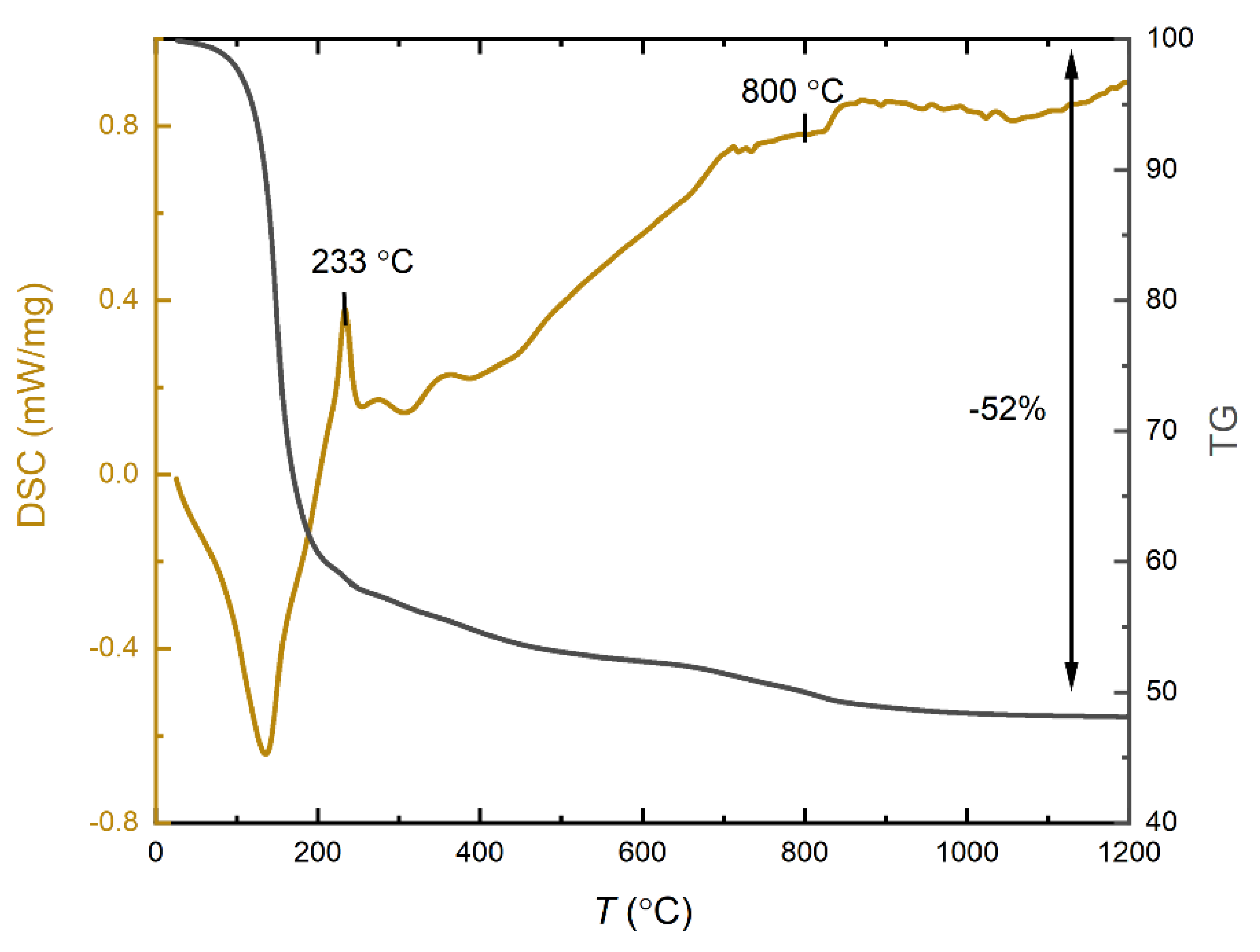
Figure 2.
XRD of C-MoFeNiP samples heat treated at different temperatures.
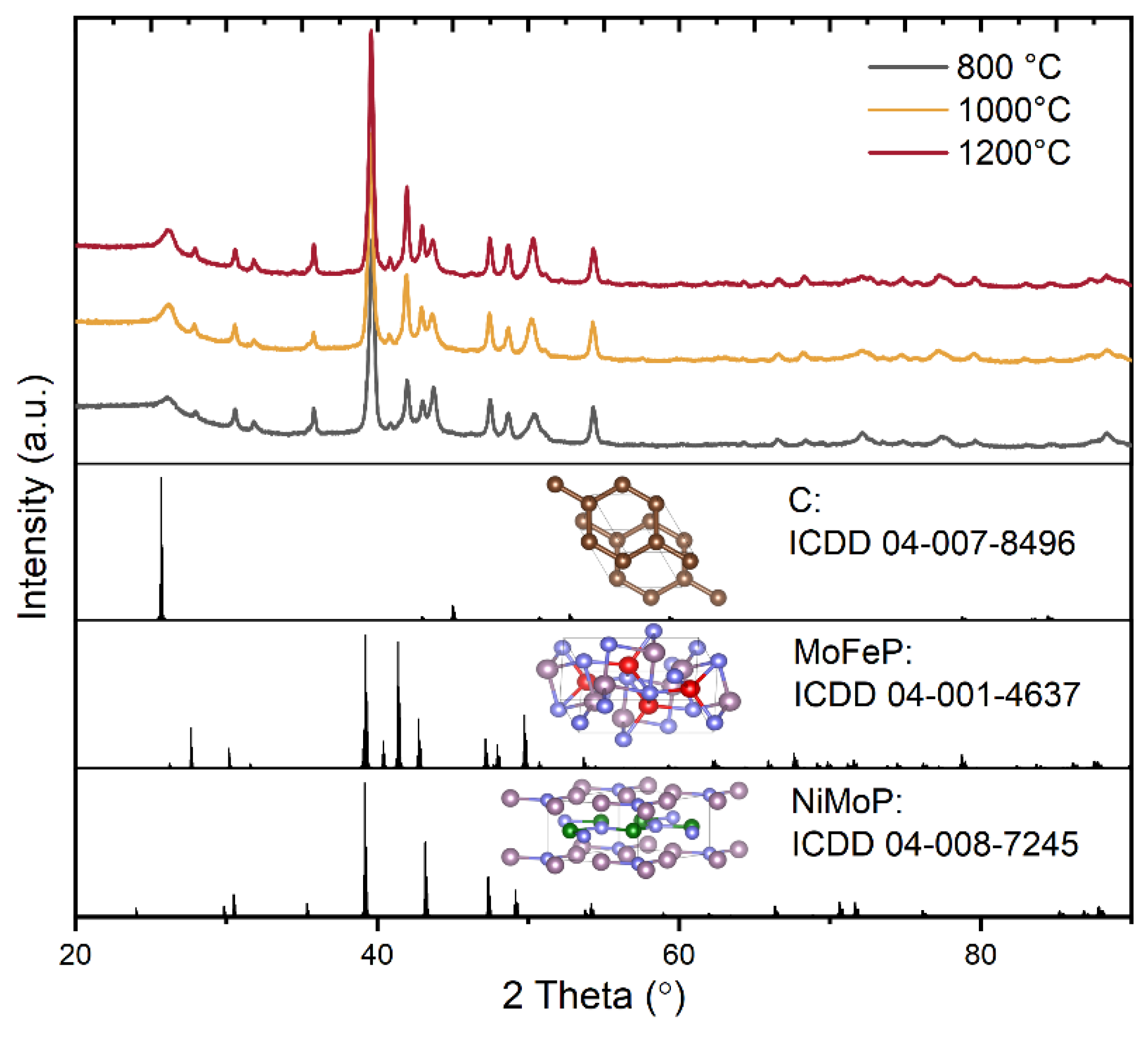
Figure 3.
Raman spectra of C-MoFeNiP samples treated at different temperatures with the ID/IG ratio.
Figure 3.
Raman spectra of C-MoFeNiP samples treated at different temperatures with the ID/IG ratio.

Figure 4.
SEM image of the C-MoFeNiP-1000: (a) dispersion of MoFeNiP particle within the carbon matrix, (b) size particle distribution.
Figure 4.
SEM image of the C-MoFeNiP-1000: (a) dispersion of MoFeNiP particle within the carbon matrix, (b) size particle distribution.
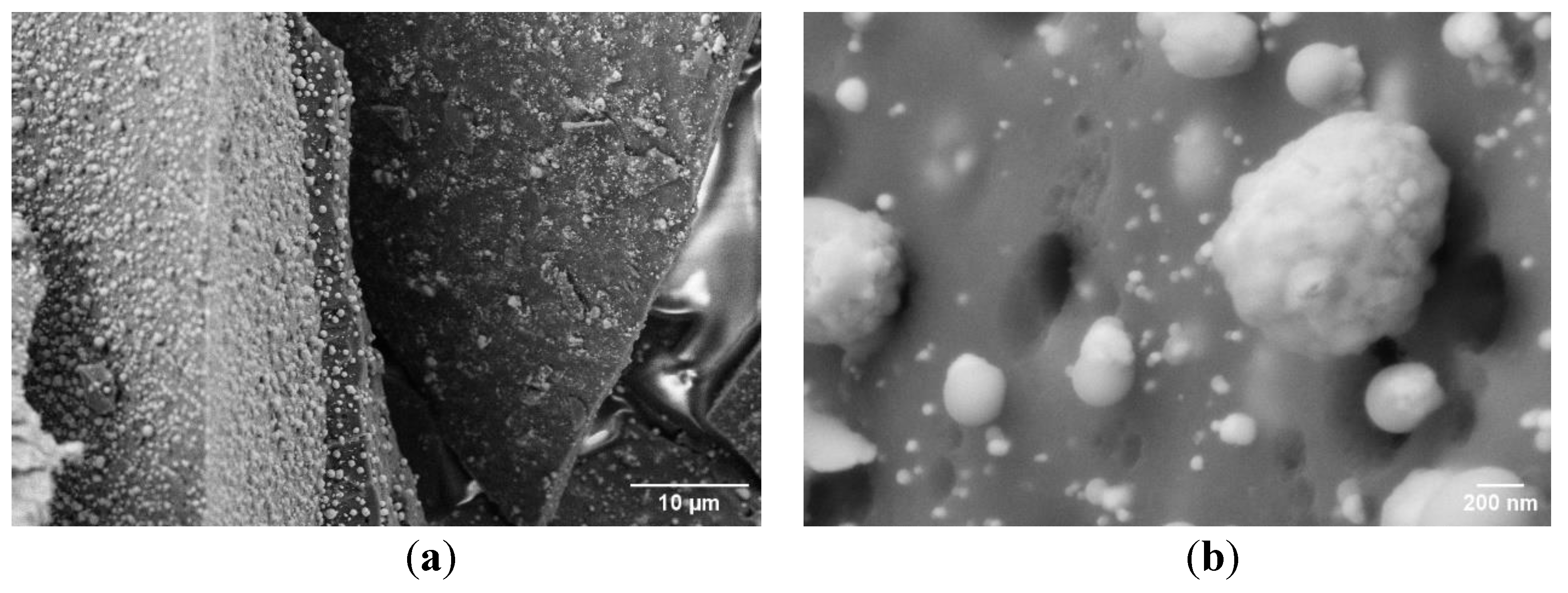
Figure 5.
SEM images and coressponing mappings for (a) MoFeNiP-800, (b) MoFeNiP-1000, and (c) MoFeNiP. Elemental distributions are color-labeled as Mo (purple), Fe (red), Ni (blue), P (green), C (orange), and O (yellow).
Figure 5.
SEM images and coressponing mappings for (a) MoFeNiP-800, (b) MoFeNiP-1000, and (c) MoFeNiP. Elemental distributions are color-labeled as Mo (purple), Fe (red), Ni (blue), P (green), C (orange), and O (yellow).
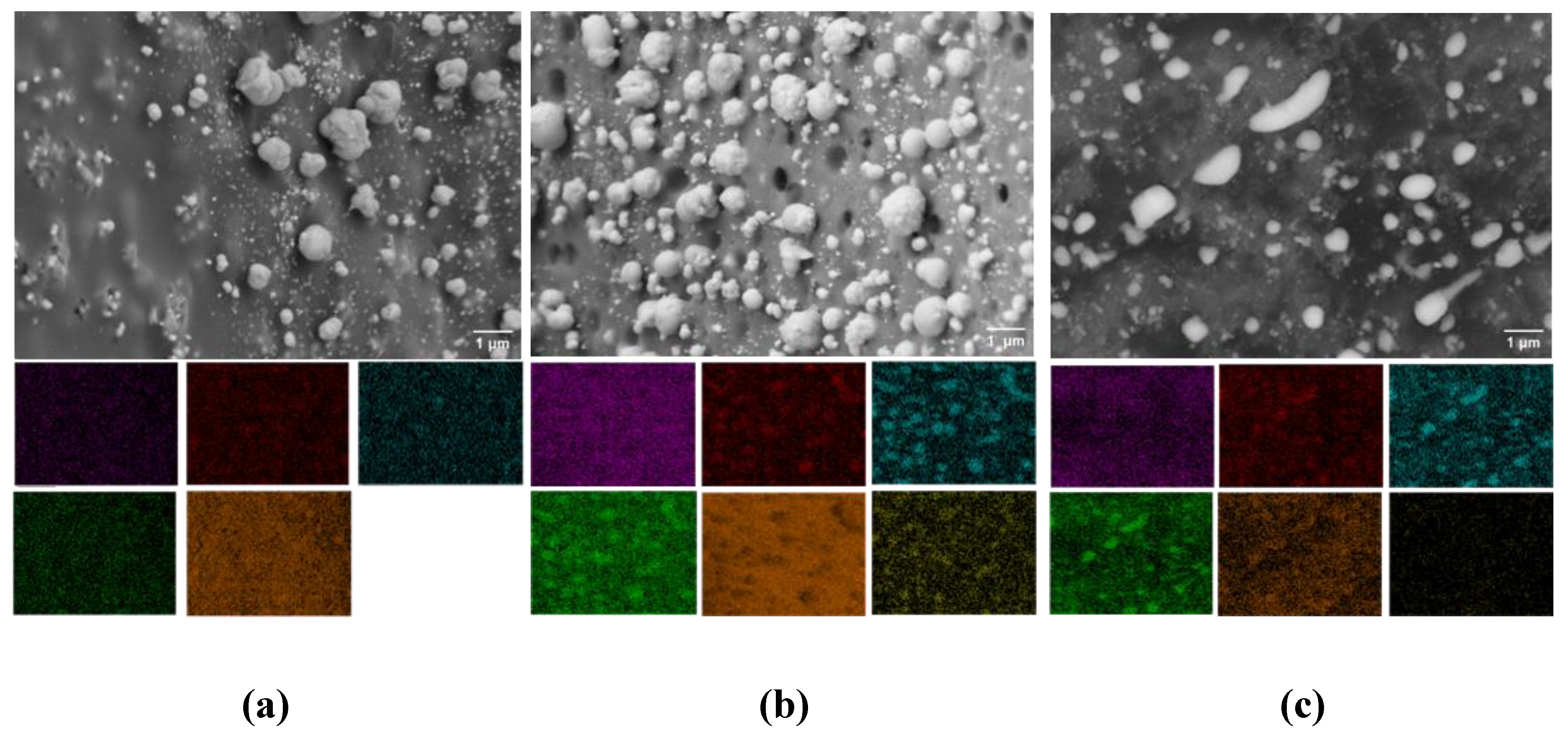
Figure 6.
(a) LSV curves of C-MoFeNiP catalysts treated at different temperatures, measured in 1 M KOH (scan rate of 1 mV s⁻¹ and rotation speed of 500 rpm); (b) Corresponding Tafel plots; (c) EIS recorded in 1 M KOH at –485 mV with the inset showing the equivalent circuit; (d) Capacitance current density vs. scan rate with Cdl values.
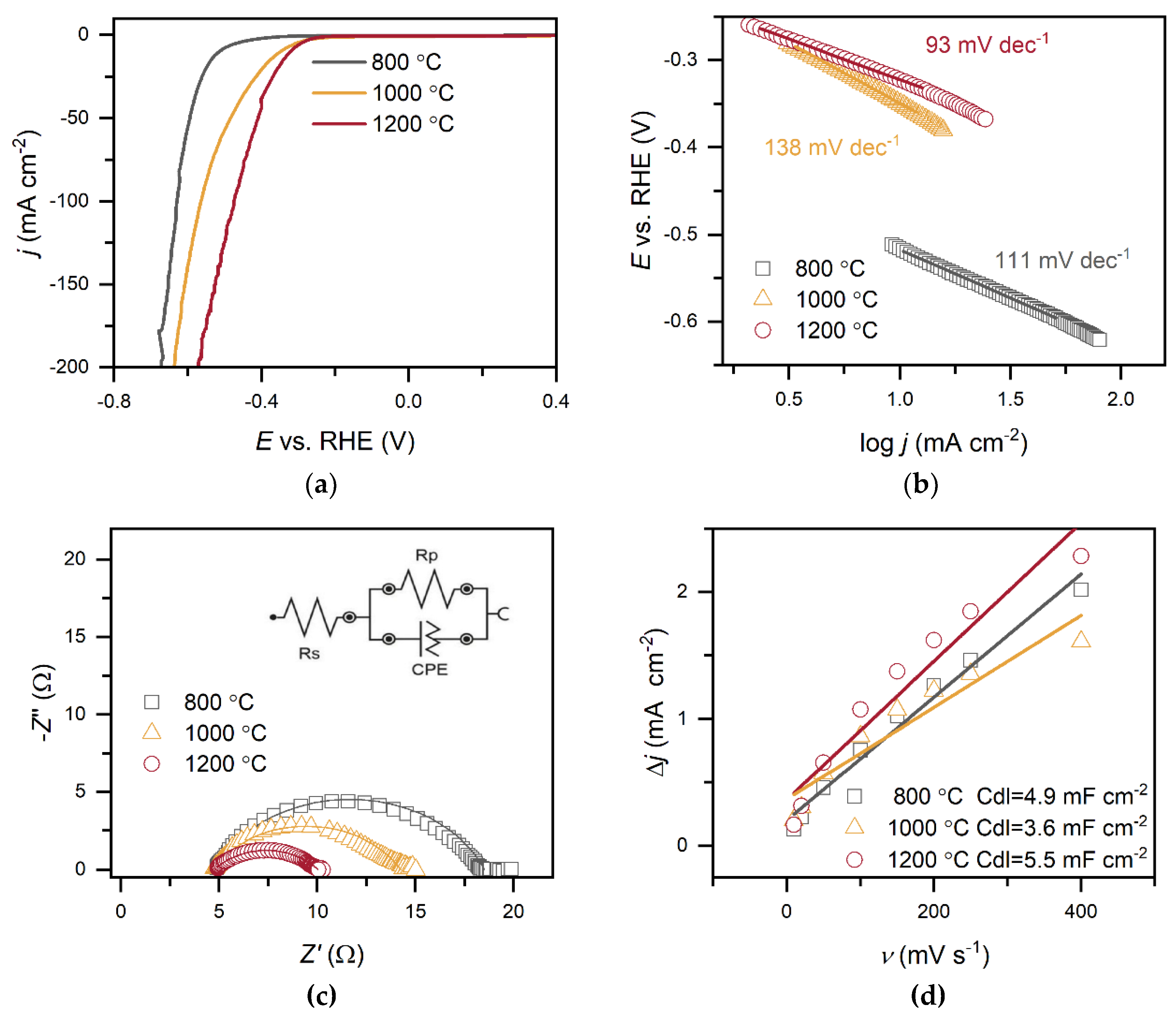
Figure 7.
(a) – (d) Electrochemical characterization of C-MoFeNiP catalysts identical as in Figure.6 performed in 0.5 M H2SO4 (LSV at 1000 rpm, EIS at –589mV) .
Figure 7.
(a) – (d) Electrochemical characterization of C-MoFeNiP catalysts identical as in Figure.6 performed in 0.5 M H2SO4 (LSV at 1000 rpm, EIS at –589mV) .
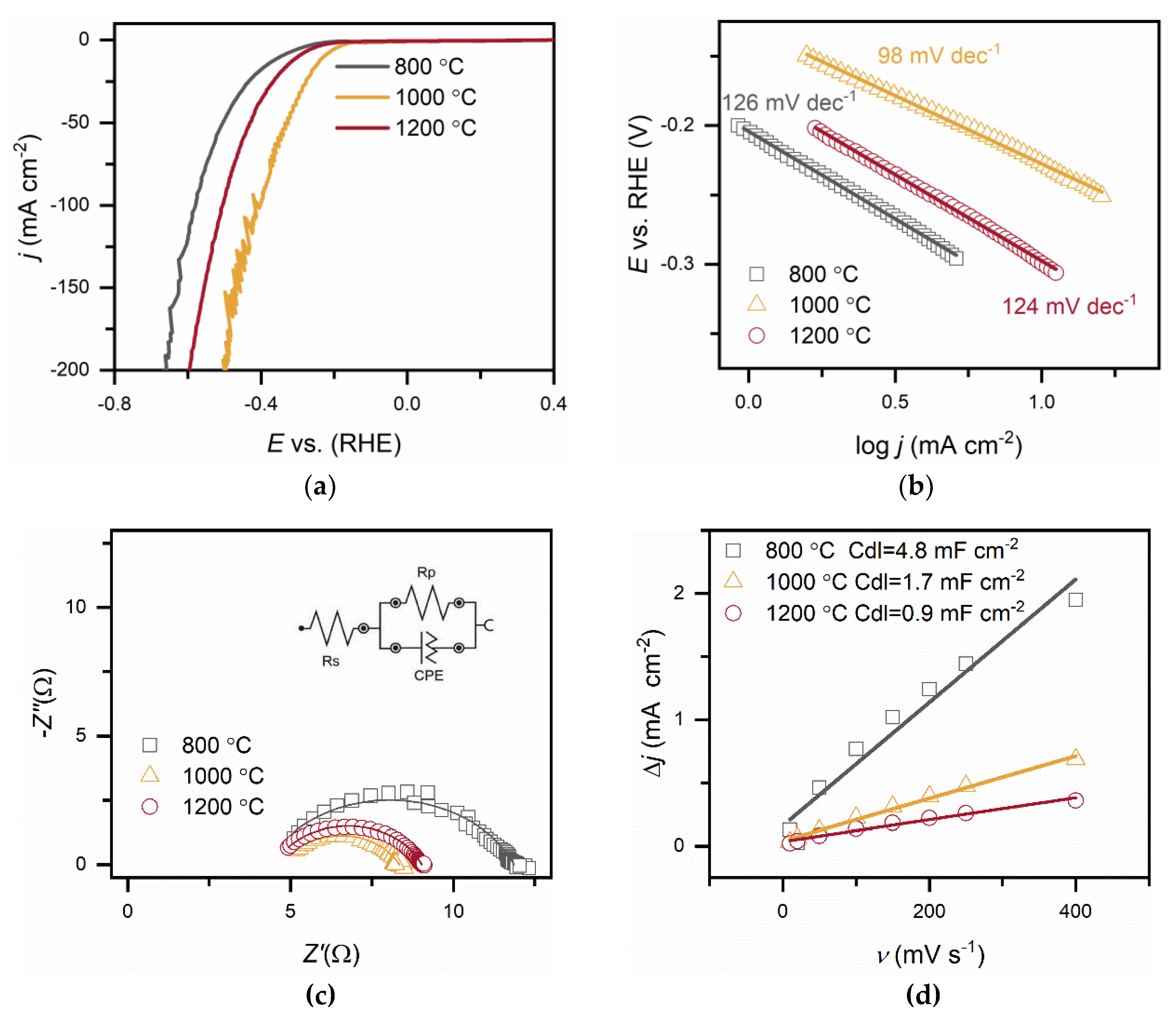
Figure 8.
Chronopotentiometric stability measurement for C-MoFeNiP for 22 hours (a) at -285 mV vs RHE in an alkaline environment, and (b) at -229 mV vs RHE in an acidic environment.
Figure 8.
Chronopotentiometric stability measurement for C-MoFeNiP for 22 hours (a) at -285 mV vs RHE in an alkaline environment, and (b) at -229 mV vs RHE in an acidic environment.
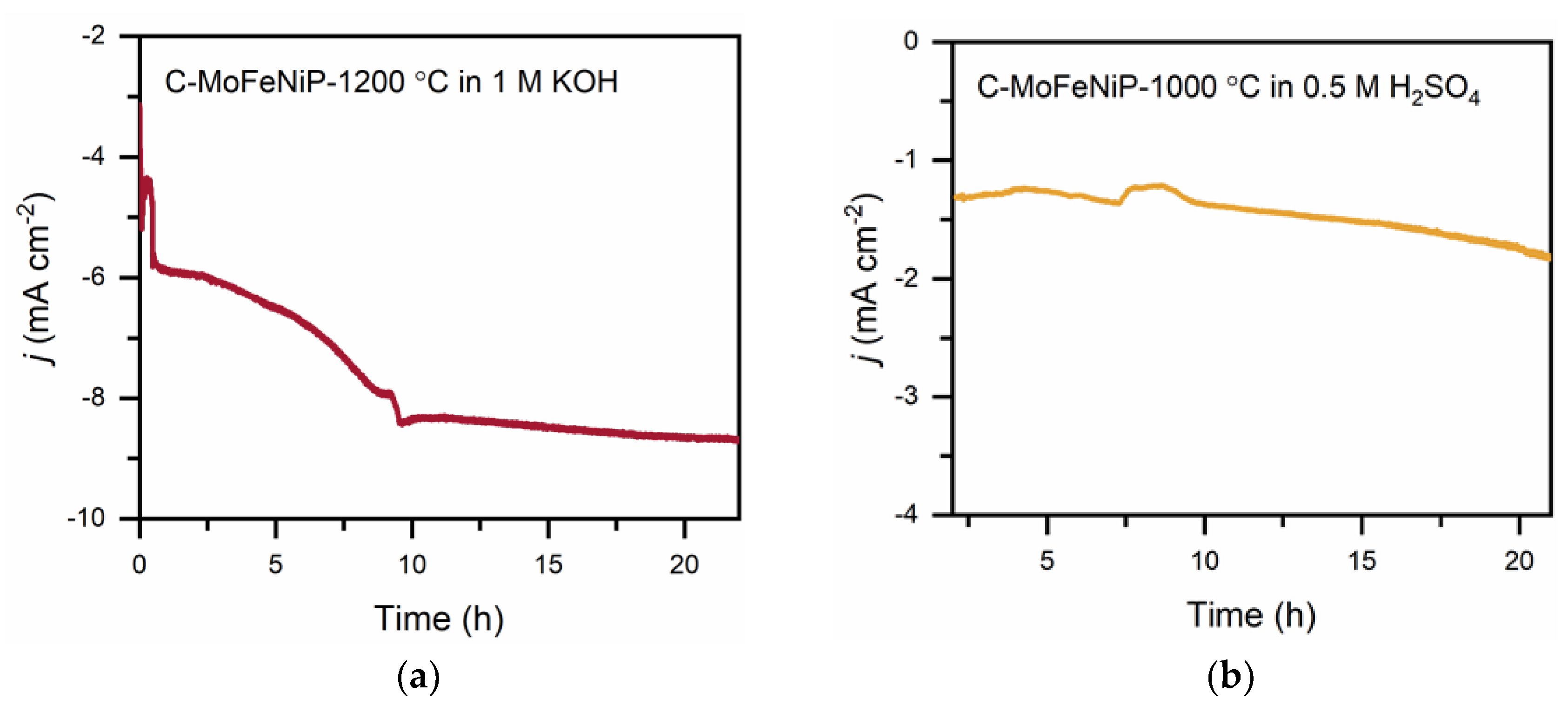
Figure 9.
SEM images of C-MoFeNiP after a 22-hour chronoamperometry stability test: a, b) post-test morphology in an acidic environment; c, d) post-test morphology in an alkaline environment.
Figure 9.
SEM images of C-MoFeNiP after a 22-hour chronoamperometry stability test: a, b) post-test morphology in an acidic environment; c, d) post-test morphology in an alkaline environment.
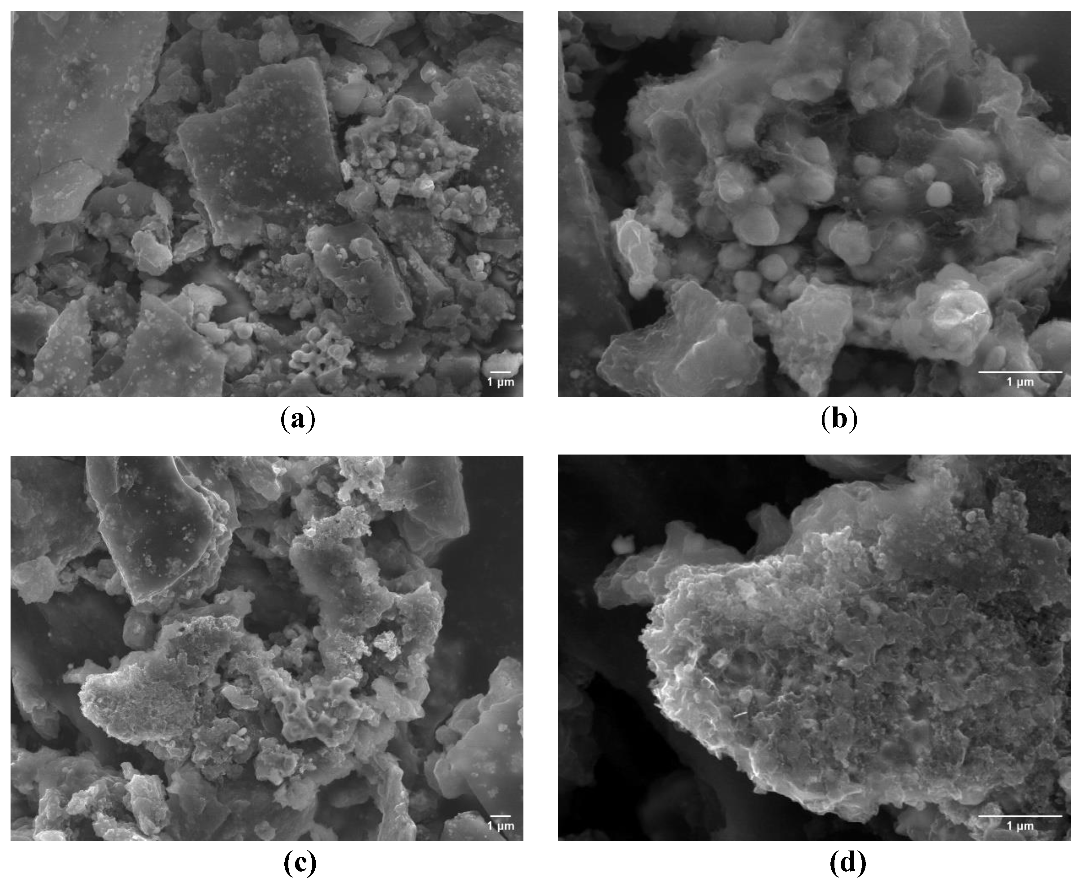

Table 1.
Elemental composition of C-MoFeNiP samples treated at different temperatures obtained from EDX analysis.
Table 1.
Elemental composition of C-MoFeNiP samples treated at different temperatures obtained from EDX analysis.
| Element (at%) | C-MoFeNi-800 | C-MoFeNi-1000 | C-MoFeNi-1200 |
|---|---|---|---|
| C | 89.6 | 90.2 | 82.9 |
| Ni | 2.3 | 1.3 | 5.6 |
| P | 0.9 | 1.3 | 3.6 |
| Fe | 2.2 | 0.8 | 3.2 |
| O | 4.4 | 5.6 | 2.8 |
| Mo | 0.6 | 0.8 | 1.9 |
Table 2.
Summary of electrochemical parameters measurements in 1 M KOH for C-MoFeNiP catalysts treated at different temperatures.
Table 2.
Summary of electrochemical parameters measurements in 1 M KOH for C-MoFeNiP catalysts treated at different temperatures.
| Parameters | C-MoFeNi-800 | C-MoFeNi-1000 | C-MoFeNi-1200 |
|---|---|---|---|
| LSV analysis | |||
| η10 (mV) | 522 | 349 | 321 |
| Tafel slop (mV dec-1) | 111 | 138 | 93 |
| j0 (mA cm-2) | 2.2·10-4 | 2.8 ·10-2 | 3.4·10-3 |
| α | 0.53 | 0.43 | 0.64 |
| EIS analysis | |||
| Y0-CPE (mS·sN) | 0.19 | 0.54 | 2.2 |
| Rct (Ω) | 13.7 | 9.6 | 5.3 |
| Rs (Ω) | 4.8 | 4.7 | 4.7 |
| N-CPE | 0.742 | 0.670 | 0.562 |
| Ceff (F) | 2.3·10-5 | 3.5·10-5 | 6.7·10-5 |
| χ² | 0.03 | 0.03 | 0.003 |
| CV analysis | |||
| Cdl (mF cm-2) | 4.9 | 3.6 | 5.5 |
* η10 (mV) - Overpotential at 10 mA cm⁻², j0 - Exchange current density, α- Charge transfer coefficient, CPE - constant phase element, Y0-CPE admittance, N – CPE exponent change, Rct – charge transfere resistance, Rs - Solution resistance, Ceff - Effective capacitance, χ² - Chi-squared fitting, Cdl - Double-layer capacitance.
Table 3.
Summary of electrochemical parameters measurements in 0.5 M H2SO4KOH for C-MoFeNiP catalysts treated at different temperatures.
Table 3.
Summary of electrochemical parameters measurements in 0.5 M H2SO4KOH for C-MoFeNiP catalysts treated at different temperatures.
| Parameters | C-MoFeNi-800 | C-MoFeNi-1000 | C-MoFeNi-1200 |
|---|---|---|---|
| LSV analysis | |||
| η10 (mV) | 349 | 228 | 300 |
| Tafel slop (mV dec-1) | 126 | 98 | 124 |
| j0 (mA cm-2) | 2.4·10-2 | 4.8·10-2 | 4.0·10-2 |
| α | 0.47 | 0.60 | 0.48 |
| EIS analysis | |||
| Y0-CPE (mS·sN) | 0.030 | 0.080 | 0.054 |
| Rct (Ω) | 7.6 | 3.6 | 4.5 |
| Rs (Ω) | 4.2 | 4.8 | 4.5 |
| N-CPE | 0.741 | 0.715 | 0.746 |
| Ceff (F) | 1.5·10-6 | 3.1·10-6 | 3.1·10-6 |
| χ² | 0.03 | 0.008 | 0.001 |
| CV analysis | |||
| Cdl (mF cm-2) | 4.8 | 1.7 | 0.9 |
* Abbreviations are the same as in Table 2.
Disclaimer/Publisher’s Note: The statements, opinions and data contained in all publications are solely those of the individual author(s) and contributor(s) and not of MDPI and/or the editor(s). MDPI and/or the editor(s) disclaim responsibility for any injury to people or property resulting from any ideas, methods, instructions or products referred to in the content. |
© 2025 by the authors. Licensee MDPI, Basel, Switzerland. This article is an open access article distributed under the terms and conditions of the Creative Commons Attribution (CC BY) license (http://creativecommons.org/licenses/by/4.0/).
Copyright: This open access article is published under a Creative Commons CC BY 4.0 license, which permit the free download, distribution, and reuse, provided that the author and preprint are cited in any reuse.


