
Submitted:
10 October 2025
Posted:
13 October 2025
You are already at the latest version
Abstract
Ammonia, widely regarded as the "hydrogen carrier of the future," offers high hydrogen content, ease of production, and a well-established infrastructure for handling and transportation on a global scale. Meanwhile, ammonia cracking requires heat supply at high temperatures and induction heating provides efficient, precise, and rapid heating to conductive materials of different shapes and sizes. Therefore, this work presents a proof of concept for ammonia cracking using induction heating with 3 different reactor configurations: (1) a 3D metal workpiece; (2) a 3D metal workpiece and Ni/Al2O3 catalyst; and (3) only Ni/Al2O3 catalyst. The performance of the inductively heated reactor is also compared to the one using an electric furnace. The results showed that the reactor configuration containing both the workpiece and the catalyst was the most efficient in terms of electric power usage to achieve high temperatures quickly; the least efficient configuration is the one with just the catalyst. While the workpiece surface showed minor structural changes after time on stream, the system’s performance was not affected. Overall, the introduction of the 3D workpiece allowed for fast and uniform conversion and heating within the reactor enabling efficient and dynamic process control when applying induction heating to chemical reactors.
Keywords:
ammonia cracking
; induction heating
; electrification
; hydrogen carrier
; 3D workpiece
; internal heating
1. Introduction
The need for the energy-intensive industry to decrease greenhouse gas emissions and reduce the use of fossil fuels, as well as the search for affordable energy, have created a strong driver for ammonia as an energy carrier [1,2]. As such, ammonia can be used as a fuel in combustion processes, be reformed into hydrogen, or indeed a combination of both[3,4]. The cracking of ammonia into hydrogen:
is an equilibrium-limited, endothermic process typically run between 400 °C and 900 °C in order to achieve high conversion [5]. Ammonia, or product purification off-gases, have been proposed as fuel for providing the required energy in burners. This however leads to a significant loss in efficiency when considering the energy balance over the value chain from renewable electricity to hydrogen at end-use [6]. [6]. Moreover, the process must be sufficiently flexible to follow the intermittent demand for hydrogen from NH3 crackers, whereas conventional burners are constrained by their limited turndown ratio[7]. Instead, electrified ammonia cracking offers a potentially higher overall efficiency while offering productivity benefits [8].
Many research and development efforts are currently directed at electrification of high-temperature industrial processes by resistive, induction, and dielectric heating. Good overviews have recently been published by Leicher et al.[9] and Masuku et al. [10], for example. Recent studies demonstrate the potential of induction heating to significantly enhance catalytic performance. Most of the current applications focus on directly heating the catalyst itself, which must contain ferromagnetic (nano)particles that are affected by the electromagnetic field, demonstrating enhanced reaction performance [11,12,13,14]. Accordingly, a recent study demonstrated that a Pt/Fe3O4 nanoparticle catalyst could be inductively heated to drive CO oxidation, resulting in a more than 25-fold increase in reaction rate compared to conventional external heating [12]. Meanwhile, another work developed a composite CO2 sorbent of zeolite 13X mixed with Fe3O4, enabling rapid induction heating for TSA (temperature swing adsorption) regeneration [14]. They reported that the inductive system could deliver a heat absorption rate up to 150 W per gram of Fe3O4 (at 171 A coil current) in the sorbent, allowing CO2 desorption in under three minutes. Even highly endothermic reactions like steam methane reforming (SMR) have been targeted by using Co–Ni alloy nanoparticles on alumina as both catalyst and magnetic susceptor for SMR, achieving >90% methane conversion at ~800 °C with induction heating [15].
However, this method of inductively heating the catalyst also comes with limitations. Effective induction heating of the catalyst bed requires the presence of ferromagnetic particles in sufficient concentration and with uniform dispersion. This limits the range of catalytic processes that can benefit from induction heating technology such as the processes with catalysts that are not ferromagnetic or too expensive to be present in high quantities. In addition, when catalysts are weakly ferromagnetic, high electrical inputs are needed to reach high temperatures, reducing the economic feasibility of the process. More often than not, direct catalyst heating requires the challenging development, validation, and scale-up of new catalyst materials. Accordingly, alternative solutions have been proposed that rely on heating metallic reactor tubes directly. This brings the advantage of being able to use conventional catalysts, but suffers in terms of efficiency: heating up only the tube surface increases heat loss to the environment and creates inefficient and non-uniform heating in the catalyst bed.
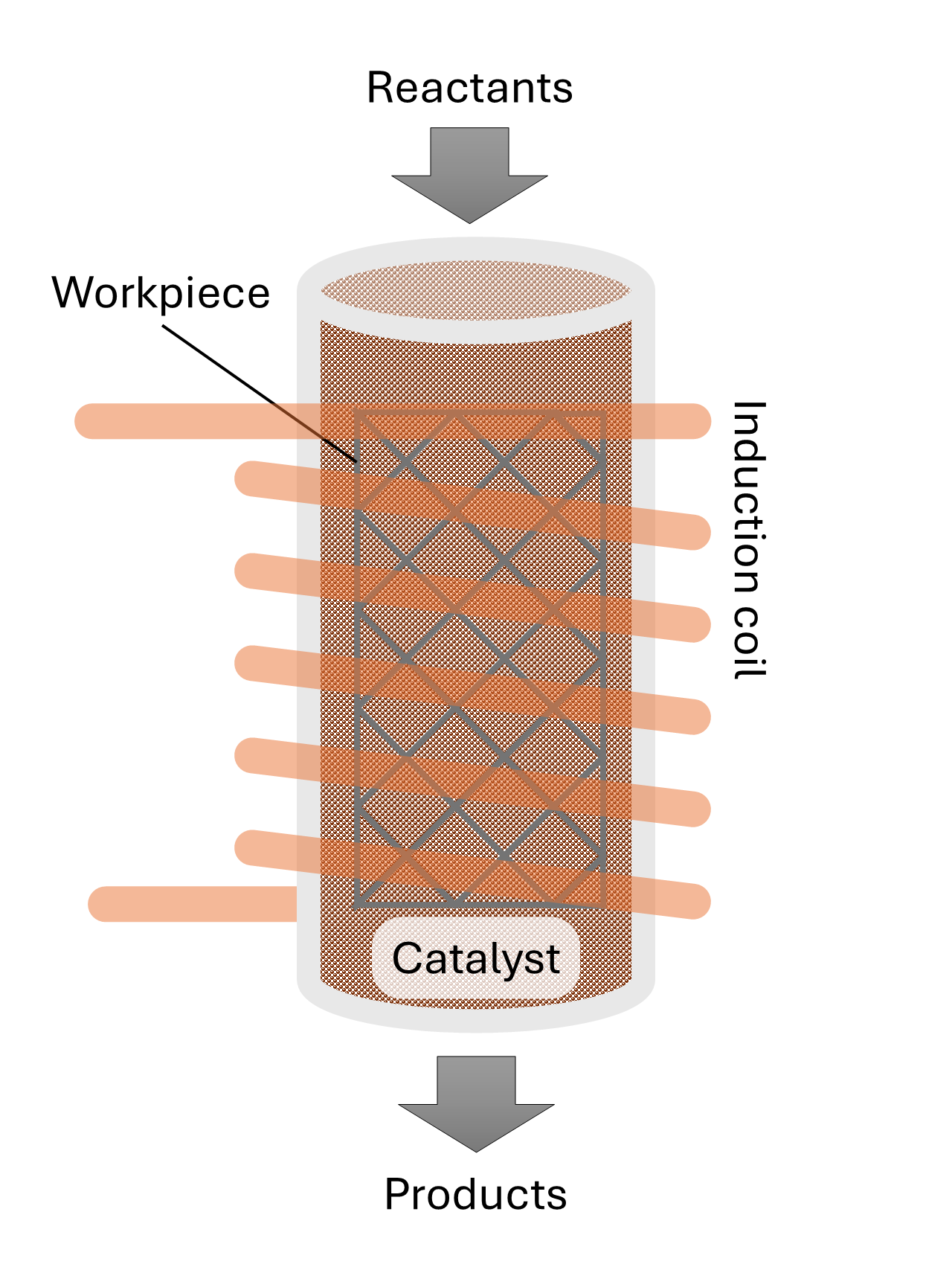
To overcome these limitations, we propose an innovative alternative design that provides high-temperature heat to thermocatalytic processes, schematically shown in Figure 1. The concept employs inductive heating through the use of a magnetically susceptible workpiece [16]In this concept, electromagnetic induction is being used to heat reactor internals without direct contact. The reactor thus comprises a non-metallic (e.g., quartz or ceramic) reactor surrounded by an induction coil, which generates alternating magnetic fields. These fields induce eddy currents in work piece, which heats up and transfers heat to the catalyst bed and the reactants inside the reactor, thereby improving energy efficiency and heating rates. A modular coil configuration additionally allows for spatially resolved heating zones. This means the temperature in the reactor can be finetuned while it also supports scalable reactor geometries. This makes the concept suitable for both laboratory-scale and industrial-scale operations. It is therefore particularly relevant for green chemistry processes, where clean, efficient, flexible and controllable heating is paramount. According to the novel concept, we focus in this study on the use of a thin, three-dimensional (3D) metal workpiece which is placed inside the catalytic bed of a quartz reactor. This design allows the catalyst to receive electromagnetic waves, and the 3D workpiece can be shaped in many forms to create a uniform and efficient heating of the bed, reducing heat loss and enhancing overall thermal efficiency.
The current paper describes experimental validation of ammonia cracking using induction heating in lab-scale experiments, employing a 3D metal structure as work piece inside the reactor as a direct heat source. The performance of the inductively heated reactor is also compared to experiments cracking ammonia in a conventional electric furnace. The electric power and current necessary to perform the experiments were measured and correlated to the temperature created inside the reactor. Finally, the energy efficiency was compared for inductive heating and conventional external heating, highlighting the benefit of induction heating in creating a more constant reactor temperature.
2. Materials and Methods
The goal of this study is to evaluate the performance of inductively heating an ammonia cracking process with a 3D metal workpiece located in the centre of a quartz reactor packed with Ni/Al2O3 (~ 65% Ni) catalyst. The experiments were performed with 3 different reactor configurations
- The metal 3D workpiece
- The metal 3D workpiece and the Ni/Al2O3 (~ 65% Ni) catalyst
- Only the the Ni/Al2O3 (~ 65% Ni) catalyst
2.1. Experimental Setup
The experimental setup used to perform the experiments can be seen in Figure 2 and the diagram detailing the different equipment can be seen in Figure 3.
In this experimental setup, a gas mixture composed of 10% ammonia and 90% argon is introduced at the bottom of a quartz reactor, which is operated in ambient pressure, and is tested in three different configurations: using only a metal 3D workpiece, using the workpiece together with a Ni/Al2O3 catalyst (containing approximately 65% nickel), and using the catalyst alone. The catalyst is mixture of Ni/Al2O3 containing approximately 65% nickel provided by Sigma-Aldrich with a surface area of around 175 m2/g and pelletized to a sieve fraction of 212–420 µm[17].
Temperature inside the reactor is measured using fiber optic sensors based on Fiber Bragg Grating (FBG) technology with 5 measurement points. This method was chosen since it is not made of metallic materials that can be affected by the electromagnetic field created by the induction heater. The signals are transmitted to a Sentea DM8125 interrogator, which supports up to eight fiber channels, each capable of reading ten sensors. The data is then sent to a computer where it can be read and analyzed.
The heating is controlled by an Ambrell Easyheat 8310 induction heater, which operates in the 150–450 kHz frequency range and delivers up to 10 kW of power and operates at frequencies between 238-247 kHz. The induction system is water-cooled, requiring a heat exchanger to manage thermal loads.
The electric power consumption is measured with a digital power meter for each experiments on all of the reactor configuration at different temperature levels. These measurements reflect the total power used by the induction heating system, also including the cooling box (Hyfra type Chilly 3-S) and the infrared pyrometer (Yokogawa UP55A), which is part of the setup for temperature monitoring, but was not used during the experiments.
The composition of the gas leaving the reactor is determined by a mass spectrometer (MS) Thermo Star from Pfeiffer Vacuum, which evaluates the signal of each component over time. The results are transferred to a computer for further interpretation.
For this work, the ammonia cracking reaction was also performed with the same catalyst and feed in an electric vertical placed furnace as seen in Figure 4. The reactor is made of steel and has similar dimensions to the quartz and the temperature measurement in this case is done by a thermocouple at the outer wall of the reactor.
2.2. Reactor Configuration
The reactor configuration used to perform the experiments can be seen in Figure 5, where the left image contains just the workpiece and the right one is filled with the Ni/Al2O3 catalyst. The detailed diagram of the reactor can be seen in Figure 6.
The glass optic fiber is placed at the center of the reactor and provides five temperature measuring points (FBG), which are represented by the red points in Figure 6. These FBGs are placed 8 mm apart from center to center, being able to determine the temperature profile along the reactor length. The workpiece is made of EN 1.0314 steel which is a is a non-alloy steel with a typical composition of 99.365 to 99.78% Iron (Fe), 0.2 to 0.4% Manganese (Mn), 0 to 0.1% Silicon (Si), 0.020 to 0.060% Aluminum (Al), and 0 to 0.030% Carbon (C). The workpiece was assembles by folding and welding a Mesh wire sheet with square grid opening of 3.918 X 3.918 mm and wire thickness of 700 µm.
3. Results
To evaluate the performance of the 3D workpiece in providing heat to the reaction zone, the three concepts will be compared in terms of temperature distribution inside the reactor, heating rates, and power consumption. Additionally, the gas outlet composition will be monitored through the MS, specifically the ammonia signal for both the catalyst-workpiece system and the catalyst alone. Finally, the ammonia conversion in the reactor using the workpiece-catalyst system will be compared with results from a similar analysis conducted in an electric oven to assess whether electromagnetic heating of the catalyst affects reaction performance.
3.1. Electric Power and Current
After the experiments were completed, the correlation between outlet temperature and electric power was created and can be seen in Figure 7.
The performance of using just the catalyst as heat source was measured and used as the benchmark of the direct catalyst heating concept as discussed in the Introduction. However, the heating in this case is highly inefficient since a lot of electric power is required to reach even lower temperatures in spite of the high nickel loading. For example, to reach a temperature of 116 °C, the configuration with only the catalyst requires 138 W, meanwhile the configurations with the workpiece require only 44 W to reach similar temperature.
The 2 configurations containing the workpiece present similar behavior until around 530 °C when the power curve of the reactor with just the workpiece start to rise steeply. This can be associated to increased heat losses at high outlet gas temperatures and the system needs to supply more electrical power to maintain the temperature. Meanwhile the power curve for the catalyst + workpiece keeps rising at a constant pace due to the catalyst contributing to distributing and retaining of heat across the reactor bed, reducing overall heat losses. Even with the lower magnetic susceptibility of the nickel catalyst, compared to that of the iron workpiece, the catalyst starts to contribute to the inductive heating. At around 650 °C the workpiece alone requires about 135 W, while the combined system reaches the same temperature using only 97 W, making this the most efficient reactor configuration for higher temperatures. However, at lower temperatures, the catalyst + workpiece reactor requires slightly less electric power since it only needs to heat up the reaction gas meanwhile when the catalyst is added, there is a higher mass that needs to be heated.
These results further validate our claims that relying on catalysts to provide heat is not always an effective strategy and the use of a workpiece can drastically improve the efficiency of the power usage.
Alternatively, the experiments with the electric tube oven demanded on average 225 W to heat up the furnace form 20 °C to 600 °C and later required 178 W to keep the furnace at 600 °C. Meanwhile, to operate the induction heating at 600 °C the reactors with the workpiece and with both workpiece and catalyst needed 110 W and 93 W, respectively.
These results indicate that, in terms of electric power usage, the most efficient reactor configuration at high temperatures is when the catalyst and workpiece are used together; followed by the workpiece alone; the electric furnace and the least efficient configuration is the one with just the catalyst.
3.2. Temperature Profile of the Reactor with Just the Workpiece
Figure 8 represents the heating rate of the reactor with just the workpiece inside to determine its performance without the effect of the catalyst.
These experiments involved increasing the power input of the induction heating device to determine the response time and heating rate inside the reactor, starting from ambient until the desired temperature. The reactor achieved an initial heating rate of 600 °C per minute, reaching the 650 °C setpoint in about 3 minutes and stabilizing at that temperature. The temperature inside the reactor was kept constant for the desired amount of time and the initial cooling rate was 434 °C per minute, requiring 7 minutes to return to ambient temperature from 650 °C.
When analyzing the temperature profile inside the reactor, it was observed that the three measurement points near the end of the reactor (FBG 3, 2 and 1) reached similar temperatures after the 370 °C setpoint. However, the temperature sensor near the inlet (FBG 5) showed significantly lower temperatures with up to 80 °C difference, due to the gas entering the reactor at ambient temperature. At the highest temperature setpoint, the temperature distribution along the reactor was uniform, except near the inlet.
Therefore, the induction heating of the reactor with just the workpiece proved to be highly effective in achieving rapid and uniform heating within the reactor. The rapid heating and cooling rates demonstrate the system’s potential for precise and dynamic temperature control.
3.3. Catalyst: Temperature Profile and Ammonia Signal
Figure 9 shows the temperature profile inside the induction heating reactor (left axis) and MS signal for ammonia with just the Ni/Al2O3 ( 65% Ni) catalyst heat source.
With the Ni/Al2O3 (~65% Ni) catalyst as the only heat source, the temperature profile in the middle region of the reactor (FBG 2, 3 and 4) rises higher than at the extremities (FBG 1 and FBG 5). This results show that the temperature profile in the reactor is not uniform for a maximum reactor operating temperature of 124 °C. The reaction temperature was not increased further due to elevated electric power demand, as seen in Section 3.1.
On the right axis of the reactor, the MS signal that indicates the ammonia content in the reaction gas can be found. For this catalyst, ammonia only starts being converted when temperatures are around 200 °C. The change in the signal is due to adsorption and desorption of the ammonia on the catalyst based on the temperature difference generated by the catalyst particles being heated by the induction heater. Initially, ammonia is adsorbed on the catalyst surface, and as the temperature increases, desorption peaks are observed
This phenomenon is also found in conventionally heated rectors, where energy is delivered from the outside of the reactor toward the catalyst bed, which results in slower temperature rise and more gradual desorption of ammonia across the surface. Making this desorption peak not easily noticeable. However in induction heating of a catalyst, the particles are directly heated, producing rapid and localized heating inside the bed, leading to more pronounced desorption peaks.
From the last ammonia signal change in Figure 9, there are 2 peaks, the first relates to the ammonia release before the entire reactor reaches its maximum temperature, because the local catalyst temperature has already risen enough to trigger desorption. Then the signal starts to drop until it reaches the signal corresponding to the ammonia flowing through the reactor, represented by the second peak. When the induction heating is turned off and temperature goes down, ammonia is again adsorbed on the catalyst surface, and the signal drops.
3.4. Catalyst + Workpiece: Temperature Profile and Product Composition
Figure 10 represents the heating rate of the reactor with the workpiece and the catalyst inside.
The reactor configuration with both the workpiece and the catalyst present shows that the behavior of the heating curves is a combination of both graphs, with each component present individually.
When compared to the concept with just the workpiece, one of the main differences is that the heating rate is much lower. At a temperature setpoint of around 590 °C, the combined workpiece–catalyst system achieves a rate of approximately 134 °C per minute, requiring nearly 13 minutes to reach the maximum temperature, but it does not fully stabilize. In contrast, when using only the workpiece, the reactor reached 581 °C at a rate of approximately 500 °C per minute, stabilizing at the target temperature in just 3.7 minutes. This shows that heating with both sources is roughly three times slower.
Another noticeable characteristic is that the temperature distribution along the reactor is less uniform, more similar to the results using just the catalyst. For similar temperature setpoints, the reactor with just the workpiece showed an average temperature difference between the coolest point near the inlet (FBG 5) and the hottest point in the reactor(FBG 1 or 2), is approximately 70 °C. In contrast, when the catalyst is added, this temperature difference increases to around 150 °C. The catalyst does not contribute significantly to the heating of the gas, as the electrical power is insufficient to cause any significant heating. The primary reason for this behavior is that when the catalyst is introduced in addition to the gas, a much larger solid mass needs to be heated making it more difficult for heat to spread evenly throughout the bed. As a result, the overall temperature distribution along the reactor becomes less uniform.
In Figure 11, the mass spectrometer signals of the components present in the gas leaving the reactor can be seen and correlated with the temperature profiles in Figure 10.
As discussed in chapter 3.3, the induction heating of the catalyst creates noticeable adsorption–desorption curves, but in the case of catalyst+ workpiece, this signal is significantly sharper, particularly at elevated temperatures.
At lower temperatures, the ammonia signal remains above zero even after the desorption peak because a constant flow of ammonia continues to pass through the reactor without being converted. The catalyst mainly adsorbs and releases ammonia, but the temperature is not yet high enough to complete the cracking of the feed, which remains unreacted. By contrast, at higher temperatures, the ammonia profiles become sharper and are immediately followed by a signal that drops to nearly zero. This indicates that after the initial burst of desorbed ammonia, the incoming feed is fully consumed through catalytic decomposition into nitrogen and hydrogen.
Furthermore, the conversion process appears to exhibit highly dynamic behavior. Each heating cycle produces a nearly immediate change in the chemical composition at the reactor outlet, which is directly linked to the temperature change created by the induction heating device. Once the reactor temperature is high enough to complete the reaction, the conversion from ammonia to hydrogen and nitrogen can rise from nearly zero to full within the same time frame. Such fast kinetics are difficult to achieve with conventional heating, where the temperature increases gradually from the wall to the center. The fast response of both the temperature and gas-phase signals reinforces the advantages of induction heating in catalytic systems.
3.5. Catalyst + Workpiece: Ammonia Conversion on Induction Heating and Electric Furnace
The conversion curves presented in Figure 12 show the relationship between outlet gas temperature and ammonia conversion for both induction heating (catalyst + workpiece) and a conventional electric furnace with a reactor tube filled with the same catalyst, plotted against the theoretical equilibrium line.
The conversion curves demonstrate that the Ni/Al2O3 catalyst achieves a steady increase in conversion with temperature, reaching complete decomposition above 500 °C. From these measurements, no significant differences in catalytic performance between the two heating methods are observed. This suggests that induction heating does not alter the performance of the catalyst used for the ammonia cracking reaction, or that the differences cannot be determined by the measurement method used in this study.
3.6. EDX/SEM Analysis of the Workpiece
In Figure 13, the images captured with scanning electron microscopy(left), highlighting surface morphology and Energy Dispersive X-ray Spectroscopy(right) containing the color-coded elemental maps indicating the presence of various elements. The top 2 pictures refer to the unused workpiece and the bottom 2 pictures refer to the workpiece after all of the experiments have been completed.
The unused workpiece displays a smoother surface with visible machining marks and limited localized defects. After the experiments, the workpiece exhibits a rougher texture, with more pronounced irregularities, indicating structural changes likely caused by thermal cycling and chemical interaction during the experiments. These transformations are typical in catalytic and high-temperature environments and reflect the material’s adaptation to stress and reactive conditions. The elemental mapping also highlights variations in the distribution of elements which can be seen in details in Table 1.
First noticeable change is the increase in Fe and the decrease in Cu surface composition in the used workpiece when compared to the unused. Initially, the workpiece consisted of mostly iron coated with a copper layer, this is a common practice from some manufacturers to protect the metal workpiece from corrosion before it can be used [18]. However, this copper layer was not visible anymore after the first experiments and almost completely removed after the end of the experimental campaign. Instead, it reveals the actual composition of the metal which is mainly made of iron with some other typical components typically found in metal alloys such as Ni, C, Mn, Cr. However, it is unclear if the Ni found in the used workpiece is only due to metal alloy composition or the Ni particles from the catalyst were deposited in the surface. The oxygen content also decreased, reflecting the reducing environment of ammonia cracking reaction, which strips away the surface oxides.
Overall, there were no critical changes in the workpiece after all of the experiments were completed. The only structural changes likely caused by thermal cycling and chemical interaction are to be expected from any chemical operation with this kind of material.
4. Discussion
The study successfully investigated the performance of inductively heated ammonia cracking reactor using a 3D metal workpiece as main heat source to overcome limitations of this technology present in in literature, which consists in heating up only the catalyst particles. The experiments showed that the reactor configuration containing both the workpiece and the catalyst was the most efficient in terms of electric power usage to achieve high temperatures; followed by the workpiece alone; the electric furnace; and the least efficient configuration is the one with just the catalyst.
The most studied catalysts for ammonia cracking contain either nickel or ruthenium as the active metals. Nickel-based catalysts are widely used for ammonia decomposition due to their balance of high activity, reasonable cost, and acceptable stability [19,20]. However in specific cases where selectivity or long-term stability is crucial other materials may be preferred such as ruthenium based catalysts, which exhibit excellent catalytic activity and selectivity for ammonia decomposition and high stability [21]. However, they are expensive and usually found in small amounts( ≤ 5% wt) and not enough to generate enough heat with induction heating.
As discussed in the Introduction, most of the current applications of induction heating in chemical processes focus on directly heating the catalyst itself. However, as seen in this paper, Ni/Al2O3 catalyst, even with 65% Ni particles, was not enough to generate heat to even start cracking the ammonia at low electric power usage. If a Ru based catalyst is used with a loading of 5% wt. or less, it is unlikely that the particles will generate enough heat in an uniform way inside the reactor. This makes this configuration unable to benefit from advantages of induction heating. Therefore, the introduction of the 3D workpiece increases the flexibility of applying induction heating to catalytic reactors while allowing the catalyst particles to benefit from the electromagnetic waves. In contrast to newly developed catalyst materials, it allows the use of a conventional catalyst, while still benefiting from the advantages of induction heating [22,23].
As seen in Section 3.2, the use of the 3D workpiece alone proved to be the most effective in achieving rapid and uniform heating within the reactor. This technology allows induction heaters to be applied to thermal cracking reactions and benefit from the precise, dynamic and stable temperature control that is provided. This will limit catalyst deactivation as recently extensively reviewed by Kim et al. [24]. Furthermore, different materials and 3D designs of the workpiece can be studied to create the most optimal and uniform temperature distribution in the reactor. Furthermore, the fast response of both the temperature and gas-phase signals reinforces the advantages of induction heating in catalytic systems. The conversion process with the catalyst + workpiece system appeared to exhibit a high dynamic behavior. Once the reactor temperature is high enough to complete the reaction, the ammonia conversion can rise from zero to full in a few minutes. Such fast kinetics are difficult to achieve with other heating methods, where the temperature increases gradually from the wall to the center.
The fast adsorption and desorption cycles created by the induction heating can benefit other applications, such as the ones that require rapid and efficient gas separation. For example Pressure Swing Adsorption and Temperature Swing Adsorption systems could benefit from induction heating since they rely on fast cycles to separate gases. Furthermore, the fast adsorption-desorption cycles can potentially enhance the efficiency of reactions by quickly removing by-products and regenerating the catalyst surface, extending its lifetime. However, further testing needs to be done to confirm these claims.
Finally, the workpiece itself requires further conceptual development as well as practical validation. The currently employed workpiece already presents an improvement over for example the use of steel beads [25] in terms of allowing accessible reactor volume for catalyst particles, and localizing the heat generation. In this work, physical changes were observed to the workpiece. While no performance degradation was observed, further long-term tests will be performed to confirm the stability of the system. Moreover, the proposed workpiece can be further optimized for heat generation in terms of wire thickness and mesh size. The addition of conductive strands can further contribute to the effective thermal conductivity of the bed, while not necessarily adding circuits for eddy currents [16]. In this respect, computational fluid dynamics modeling can be used to better understand heat and gas transport inside of the reactor and optimize the overall process efficiency. In this context, Noble et al. have recently proposed configurations for reactor diameters above 1 m in diameter, provided higher voltage radio frequency sources can be developed, for the production of chemical intermediates from renewable feedstocks [26]. This could help creating an optimal design of the 3D workpiece and material choice, making induction heating even more effective for ammonia cracking and similar reactions.
5. Conclusions
This study proved experimentally the benefits and efficiency of applying induction heating to the process of ammonia cracking in lab-scale experiments with 3 different reactor configurations: (1) a 3D metal workpiece; (2) a 3D metal workpiece and Ni/Al2O3 catalyst; and (3) Ni/Al2O3 catalyst only. The performance of the inductively heated reactor is also compared to the one using an electric furnace. The results showed that the reactor configuration containing both the workpiece and the catalyst was the most efficient in terms of electric power usage to achieve high temperatures quickly; followed by the workpiece alone; the electric furnace; and the least efficient configuration is the one with just the catalyst. The introduction of the 3D workpiece in the catalytic bed exhibited a high dynamic behavior, creating fast response of both the temperature and conversion levels. Furthermore, SEM/EDX analysis confirmed no significant structural or compositional changes in workpiece after all of the experiments were completed. Overall, the use of the 3D workpiece in inductively heated reactors enhances the overall performance of the process and presents a promising solution to the challenges associated with traditional heating methods. Future research should focus on optimizing the design and material composition of the workpiece to further enhance its effectiveness.
6. Patents
The work presented in this paper, specifically related to the use of a work piece in a heterogeneous catalyst bed, builds on a concept developed earlier. Patent WO2023126484A1 describes the use of heating structures within a reactor for inductive heating, which greatly improve the heating within the reactor [16]. Placing the heating structure results in a more homogenous temperature distribution throughout the reactor interior, which may lead to higher yields, better selectivities, faster adsorbent regeneration, reduced catalyst degradation rates and higher heating rates. The heating structure is formed by connected strands and has areas that are susceptible to induction heating.
Author Contributions
Debora de Figueiredo Luiz: Conceptualization; methodology; validation; formal analysis; investigation; data curation; writing—original draft preparation; writing—review and editing; visualization; project administration. Jurriaan Boon: Conceptualization; methodology; writing—original draft preparation; writing – review & editing, Supervision; project administration; funding acquisition. Martien Koppes: Methodology, Writing – review & editing, Supervision. Marija Saric: Writing – review & editing. All authors have read and agreed to the published version of the manuscript.
Funding
This project has received funding from the Dutch Ministry for Economic Affairs and Climate Policy.
Institutional Review Board Statement
Not applicable.
Informed Consent Statement
Not applicable.
Data Availability Statement
The original contributions presented in this study are included in the article/supplementary material. Further inquiries can be directed to the corresponding author(s).
Conflicts of Interest
The authors declare no conflicts of interest. The funders had no role in the design of the study; in the collection, analyses, or interpretation of data; in the writing of the manuscript; or in the decision to publish the results.
Abbreviations
The following abbreviations are used in this manuscript:
| SMR | Steam Methane Reforming |
| 3D | Three-dimensional |
| FBG | Fiber Bragg Grating |
| MS | Mass Spectrometer |
References
- Schmidt, J.; Gruber, K.; Klingler, M.; Klöckl, C.; Ramirez Camargo, L.; Regner, P.; Turkovska, O.; Wehrle, S.; Wetterlund, E. A new perspective on global renewable energy systems: Why trade in energy carriers matters. Energy Environ. Sci. 2019, 12, 2022–2029. [Google Scholar] [CrossRef]
- Fattahi, A.; Dalla Longa, F.; van der Zwaan, B. Opportunities of hydrogen and ammonia trade between Europe and MENA. Int. J. Hydrogen Energy 2024, 83, 967–974. [Google Scholar] [CrossRef]
- Valera-Medina, A.; Vigueras-Zuniga, M.O.; Shi, H.; Mashruk, S.; Alnajideen, M.; Alnasif, A.; Davies, J.; Wang, Y.; Zhu, X.; Yang, W.; et al. Ammonia combustion in furnaces: A review. Int. J. Hydrogen Energy 2024, 49, 1597–1618. [Google Scholar] [CrossRef]
- Hossein Ali, Y.R.; Shin, D. Green Hydrogen Production Technologies from Ammonia Cracking. Energies 2022, 15. [Google Scholar] [CrossRef]
- Ashcroft, J.; Goddin, H. Centralised and Localised Hydrogen Generation by Ammonia Decomposition : A technical review of the ammonia cracking process. Johnson Matthey Technol. Rev. 2022, 66, 375–385. [Google Scholar] [CrossRef]
- Kim, J.; Huh, C.; Seo, Y. End-to-end value chain analysis of isolated renewable energy using hydrogen and ammonia energy carrier. Energy Convers. Manag. 2022, 254, 115247. [Google Scholar] [CrossRef]
- Speelman, T. Ammonia utilization in the power sector. HyDelta. /: online: https.
- Deason, J.; Borgeson, M. Electrification of Industry: Potential, Challenges and Outlook. Curr. Sustain. Energy Reports 2019, 6, 131–139. [Google Scholar] [CrossRef]
- Leicher, J.; Giese, A.; Wieland, C. Electrification or Hydrogen? The Challenge of Decarbonizing Industrial (High-Temperature) Process Heat. J 2024, 7, 439–456. [Google Scholar] [CrossRef]
- Masuku, C.M.; Caulkins, R.S.; Siirola, J.J. Process decarbonization through electrification. Curr. Opin. Chem. Eng. 2024, 44, 101011. [Google Scholar] [CrossRef]
- Pavelić, J.S.; Gyergyek, S.; Likozar, B.; Grilc, M. Process electrification by magnetic heating of catalyst. Chem. Eng. J. 2025, 505. [Google Scholar] [CrossRef]
- Adogwa, A.; Chukwu, E.; Malaj, A.; Punyapu, V.R.; Chamness, O.; Glisson, N.; Bruce, B.; Lee, S.; Zachman, M.J.; Bruce, D.A.; et al. Catalytic Reaction Triggered by Magnetic Induction Heating Mechanistically Distinguishes Itself from the Standard Thermal Reaction. ACS Catal. 2024, 14, 4008–4017. [Google Scholar] [CrossRef]
- Ponikvar, Ž.; Likozar, B.; Gyergyek, S. Electrification of Catalytic Ammonia Production and Decomposition Reactions: From Resistance, Induction, and Dielectric Reactor Heating to Electrolysis. ACS Appl. Energy Mater. 2022, 5, 5457–5472. [Google Scholar] [CrossRef]
- Gholami, M.; Verougstraete, B.; Vanoudenhoven, R.; Baron, G. V.; Van Assche, T.; Denayer, J.F.M. Induction heating as an alternative electrified heating method for carbon capture process. Chem. Eng. J. 2022, 431, 133380. [Google Scholar] [CrossRef]
- Almind, M.R. Induction-heated catalytic hydrogen productiona magnetic investigation. Citation 2020. [Google Scholar]
- Boon, J.; James, J.D.; Sebastiani, F.; Marie, R.; Aris, T.; Elzinga, G. Inductive Heating Reactors 2025. US2025050295A1, 2025 Available online: https://worldwide.espacenet.com/patent/search/family/080122645/publication/US2025050295A1? 2025. [Google Scholar]
- Sigma-Aldrich Nickel on silica/alumina, ~65 wt% loading, powder. Merck KGaA, Darmstadt, Germany. [Online]. Available: https://www.sigmaaldrich.com/NL/en/product/aldrich/208779. 2087.
- Van der Berg, J.P.; Clayton, C.R.I. Coating Iron with Copper. Sci. Am. 1852, 8, 85–85. [Google Scholar] [CrossRef]
- MCCABE, R. Kinetics of ammonia decomposition on nickel. J. Catal. 1983, 79, 445–450. [Google Scholar] [CrossRef]
- Im, Y.; Muroyama, H.; Matsui, T.; Eguchi, K. Ammonia decomposition over nickel catalysts supported on alkaline earth metal aluminate for H2 production. Int. J. Hydrogen Energy 2020, 45, 26979–26988. [Google Scholar] [CrossRef]
- Su, T.; Guan, B.; Zhou, J.; Zheng, C.; Guo, J.; Chen, J.; Zhang, Y.; Yuan, Y.; Xie, W.; Zhou, N.; et al. Review on Ru-Based and Ni-Based Catalysts for Ammonia Decomposition: Research Status, Reaction Mechanism, and Perspectives. Energy & Fuels 2023, 37, 8099–8127. [Google Scholar] [CrossRef]
- Kirschning, A.; Kupracz, L.; Hartwig, J. New Synthetic Opportunities in Miniaturized Flow Reactors with Inductive Heating. Chem. Lett. 2012, 41, 562–570. [Google Scholar] [CrossRef]
- Wang, W.; Tuci, G.; Duong-Viet, C.; Liu, Y.; Rossin, A.; Luconi, L.; Nhut, J.M.; Nguyen-Dinh, L.; Pham-Huu, C.; Giambastiani, G. Induction Heating: An Enabling Technology for the Heat Management in Catalytic Processes. ACS Catal. 2019, 9, 7921–7935. [Google Scholar] [CrossRef]
- Kim, Y.T.; Lee, J.-J.; Lee, J. Electricity-driven reactors that promote thermochemical catalytic reactions via joule and induction heating. Chem. Eng. J. 2023, 470, 144333. [Google Scholar] [CrossRef]
- Ceylan, S.; Coutable, L.; Wegner, J.; Kirschning, A. Inductive Heating with Magnetic Materials inside Flow Reactors. Chem. – A Eur. J. 2011, 17, 1884–1893. [Google Scholar] [CrossRef] [PubMed]
- Noble, J.P.P.; Bending, S.J.; Hill, A.K. Radiofrequency Induction Heating for Green Chemicals Manufacture: A Systematic Model of Energy Losses and a Scale-Up Case-Study. ACS Eng. Au 2024, 4, 450–463. [Google Scholar] [CrossRef] [PubMed]
Figure 1.
Figure 1. Inductive heating of a chemical reactor using a workpiece.
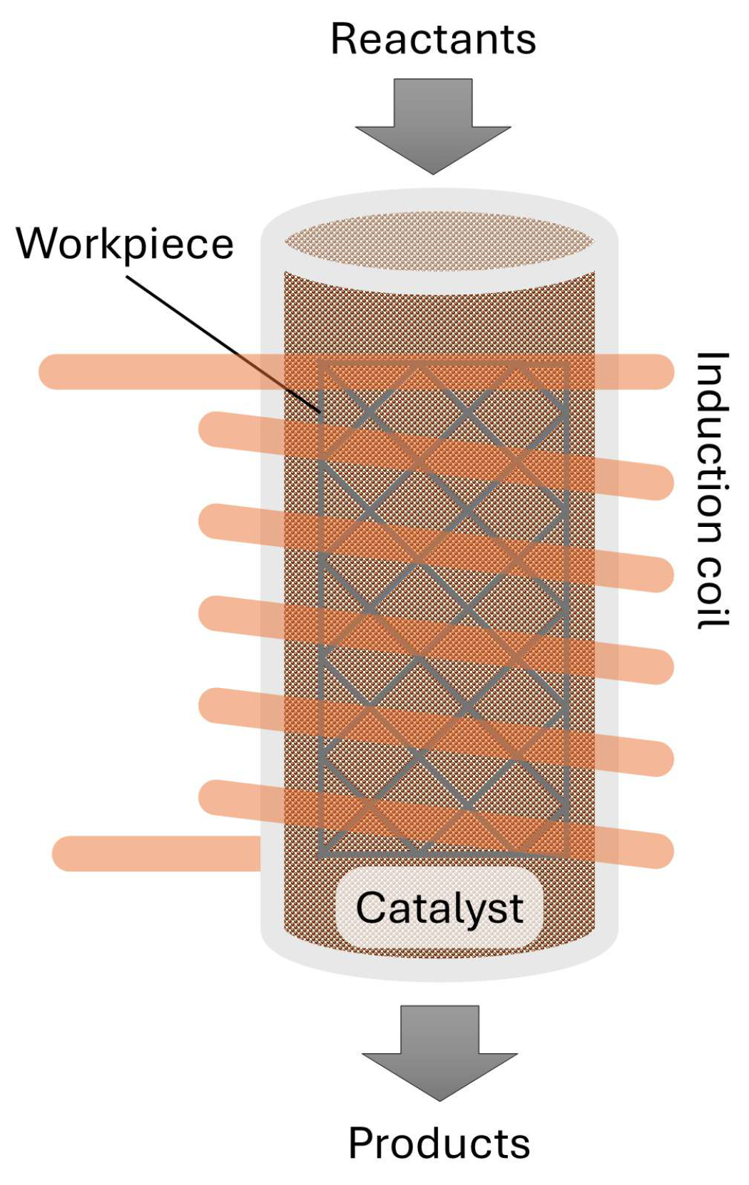
Figure 2.
Diagram of the experimental setup.
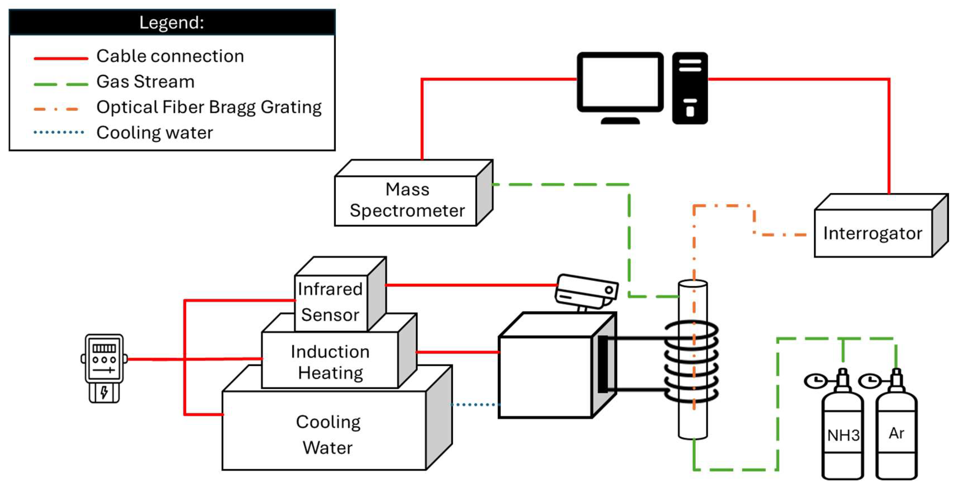
Figure 3.
Photo of the induction heating experimental setup.
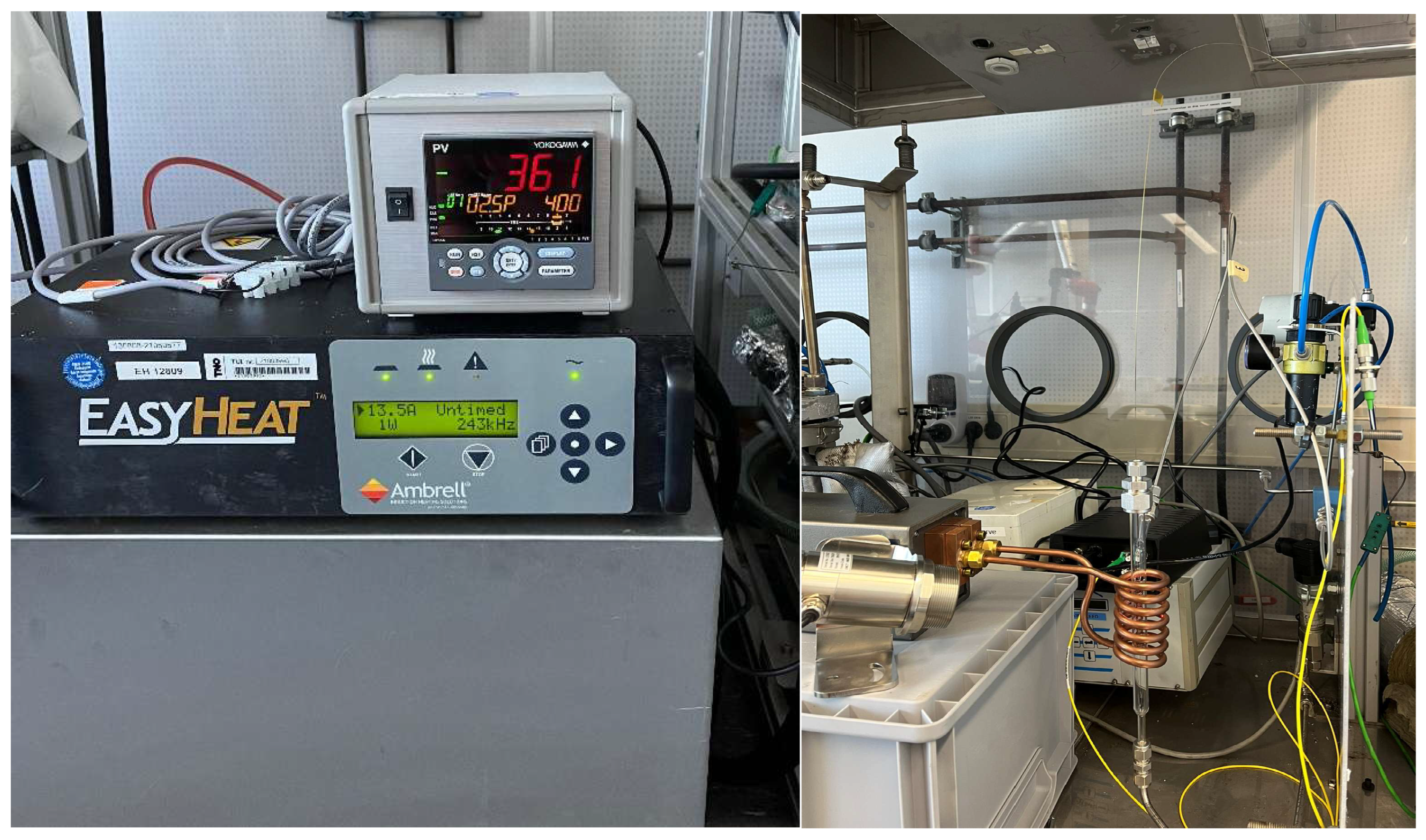
Figure 4.
Electric vertical placed furnace.
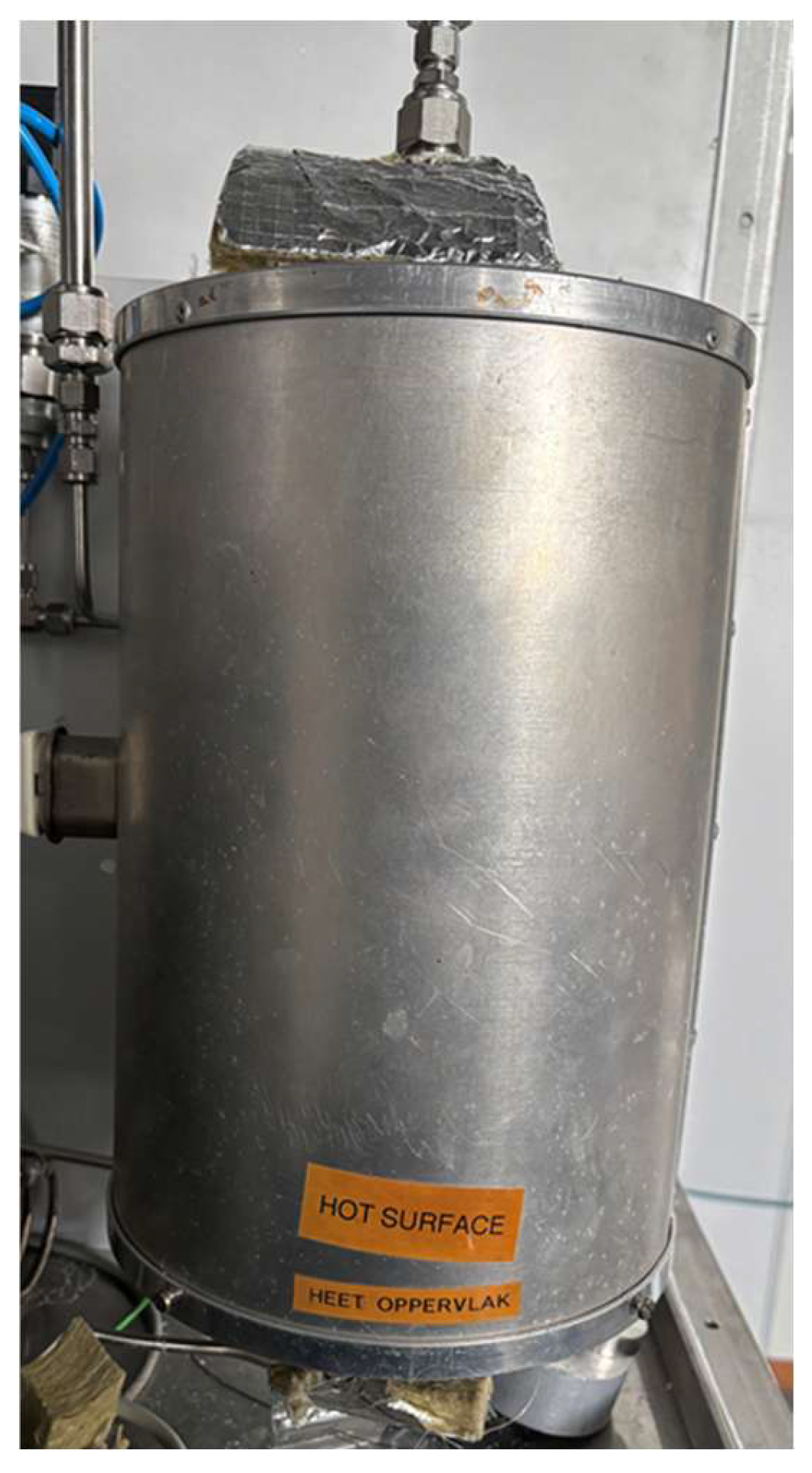
Figure 5.
Close up pictures of the quartz reactor with just the workpiece inside (left) and with the catalyst added (right) inside of the induction heating coil.
Figure 5.
Close up pictures of the quartz reactor with just the workpiece inside (left) and with the catalyst added (right) inside of the induction heating coil.
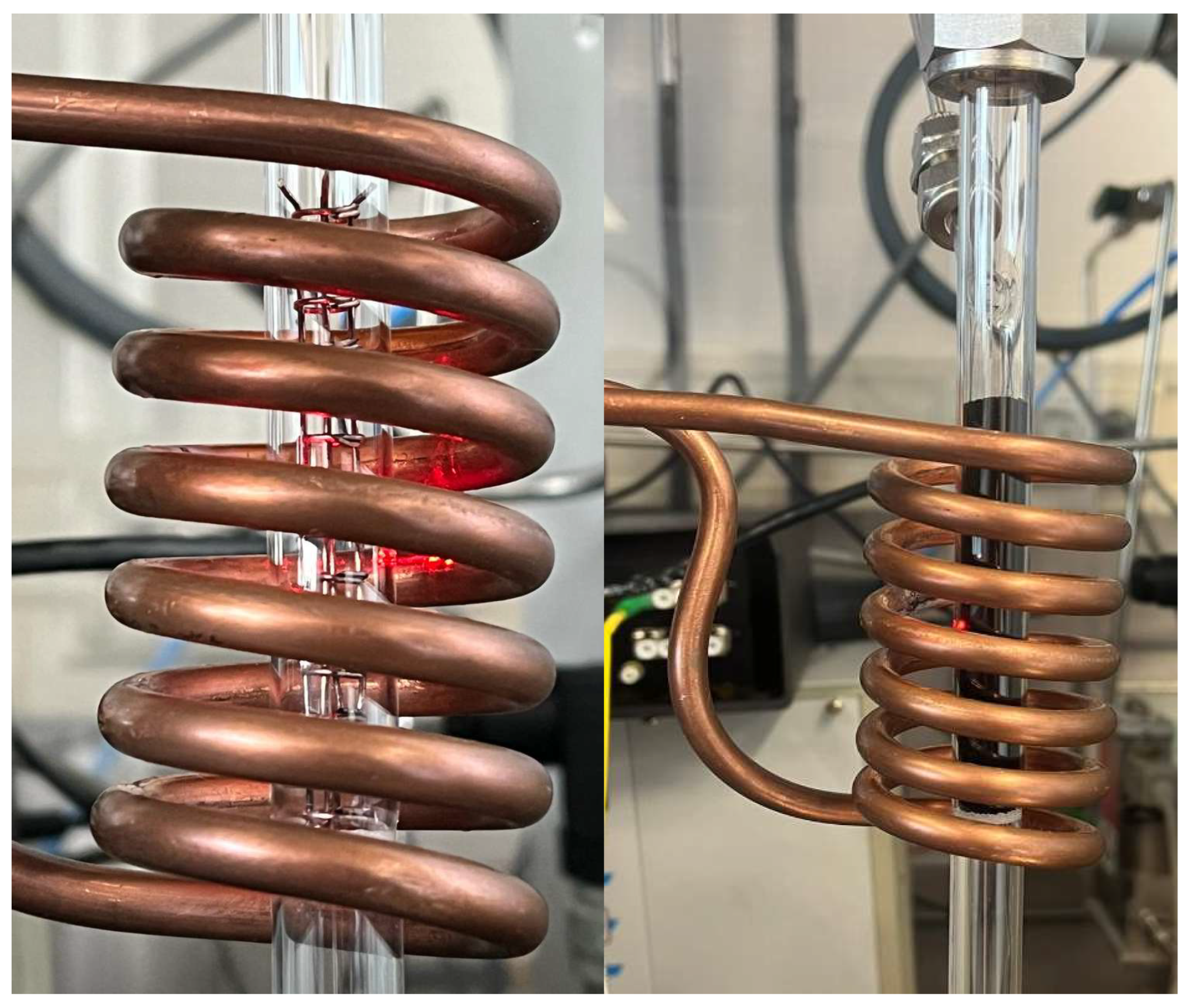
Figure 6.
Diagram with dimensions of the quartz reactor.
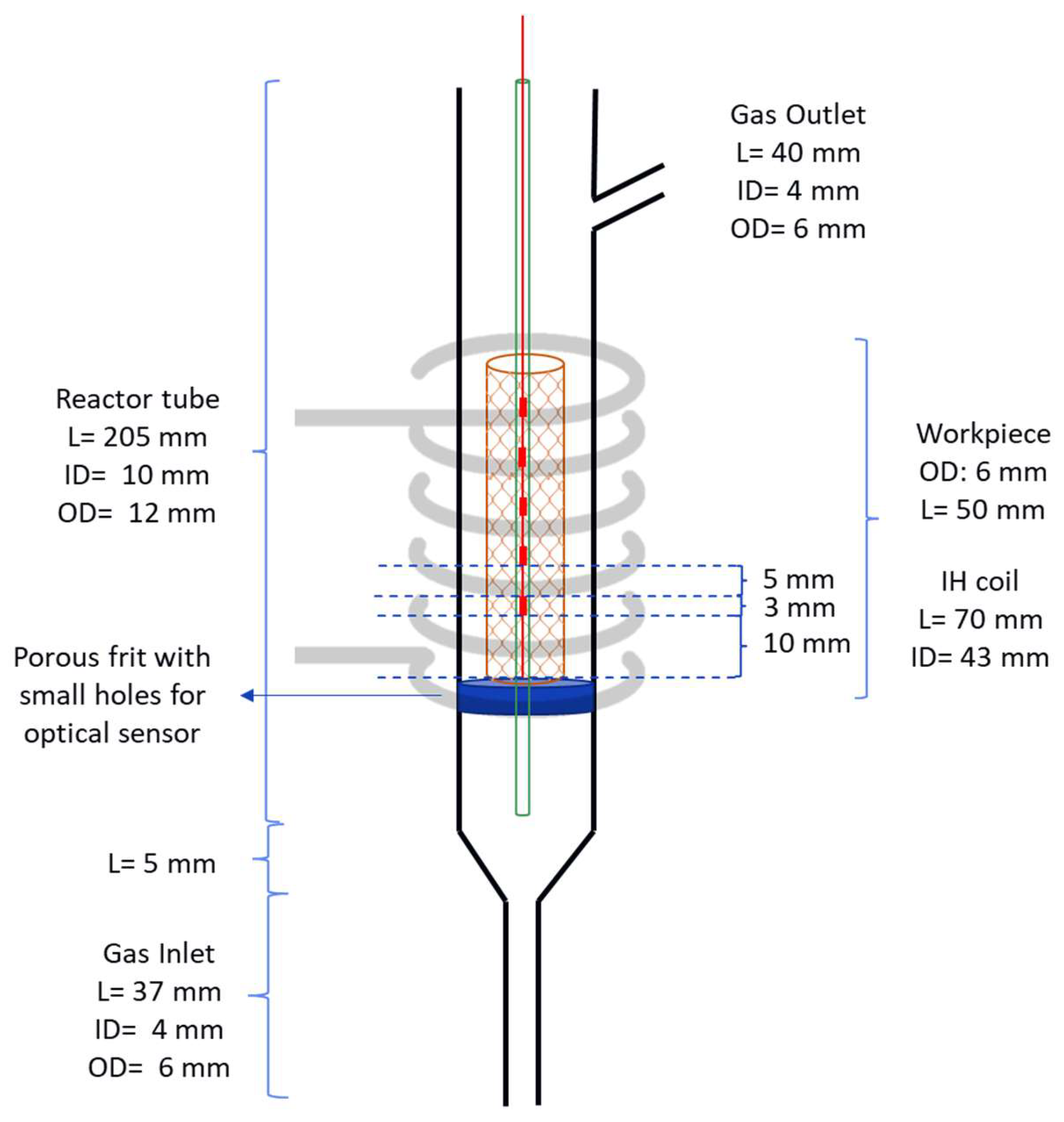
Figure 7.
Electric power necessary to heat up the reactor to a certain temperature.
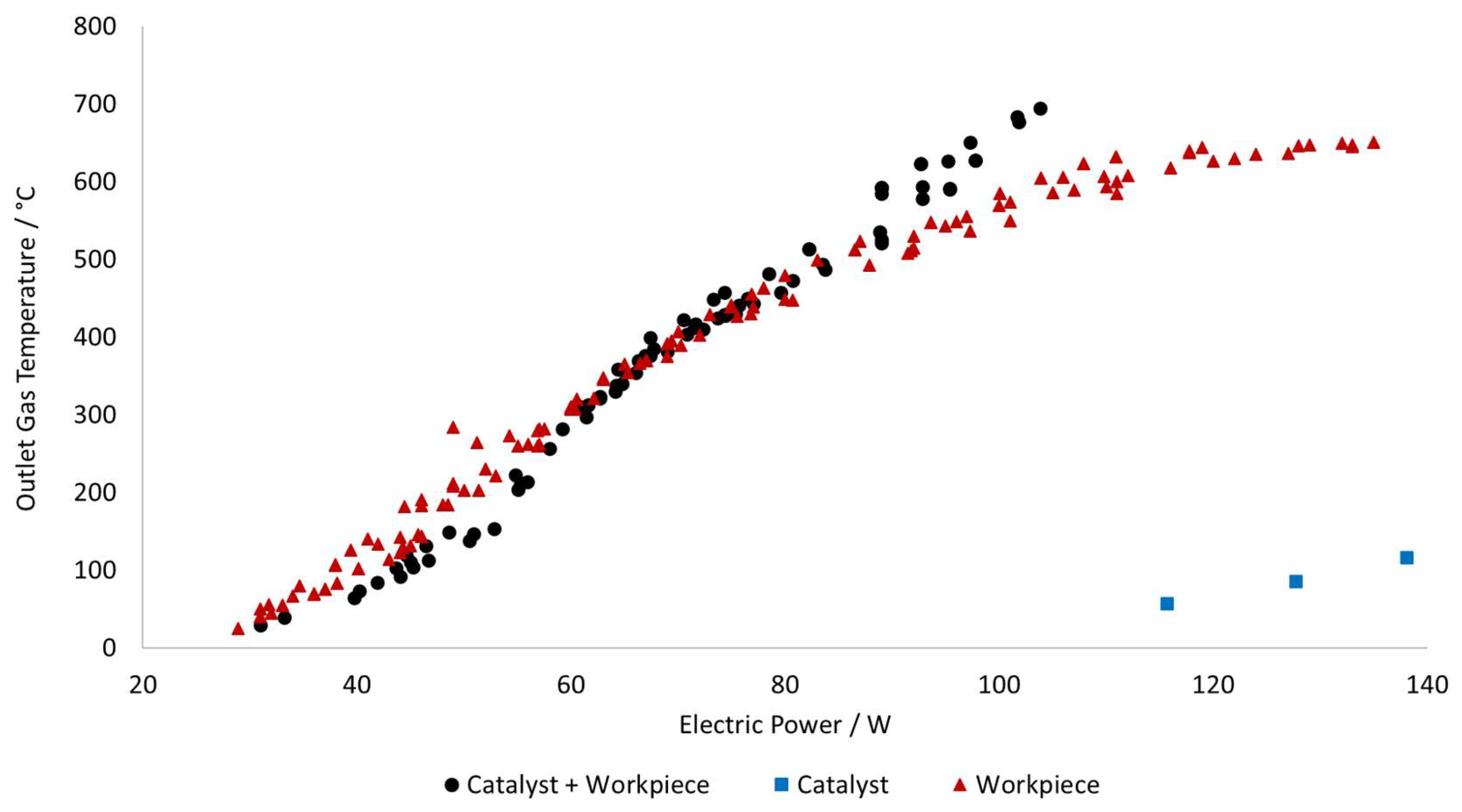
Figure 8.
Temperature profile inside the induction heating reactor with just the workpiece as heat source. FBG 1 is the measurement point closer to the outlet of the reactor and FBG 5 is the measurement point closer to the inlet of the reactor.
Figure 8.
Temperature profile inside the induction heating reactor with just the workpiece as heat source. FBG 1 is the measurement point closer to the outlet of the reactor and FBG 5 is the measurement point closer to the inlet of the reactor.
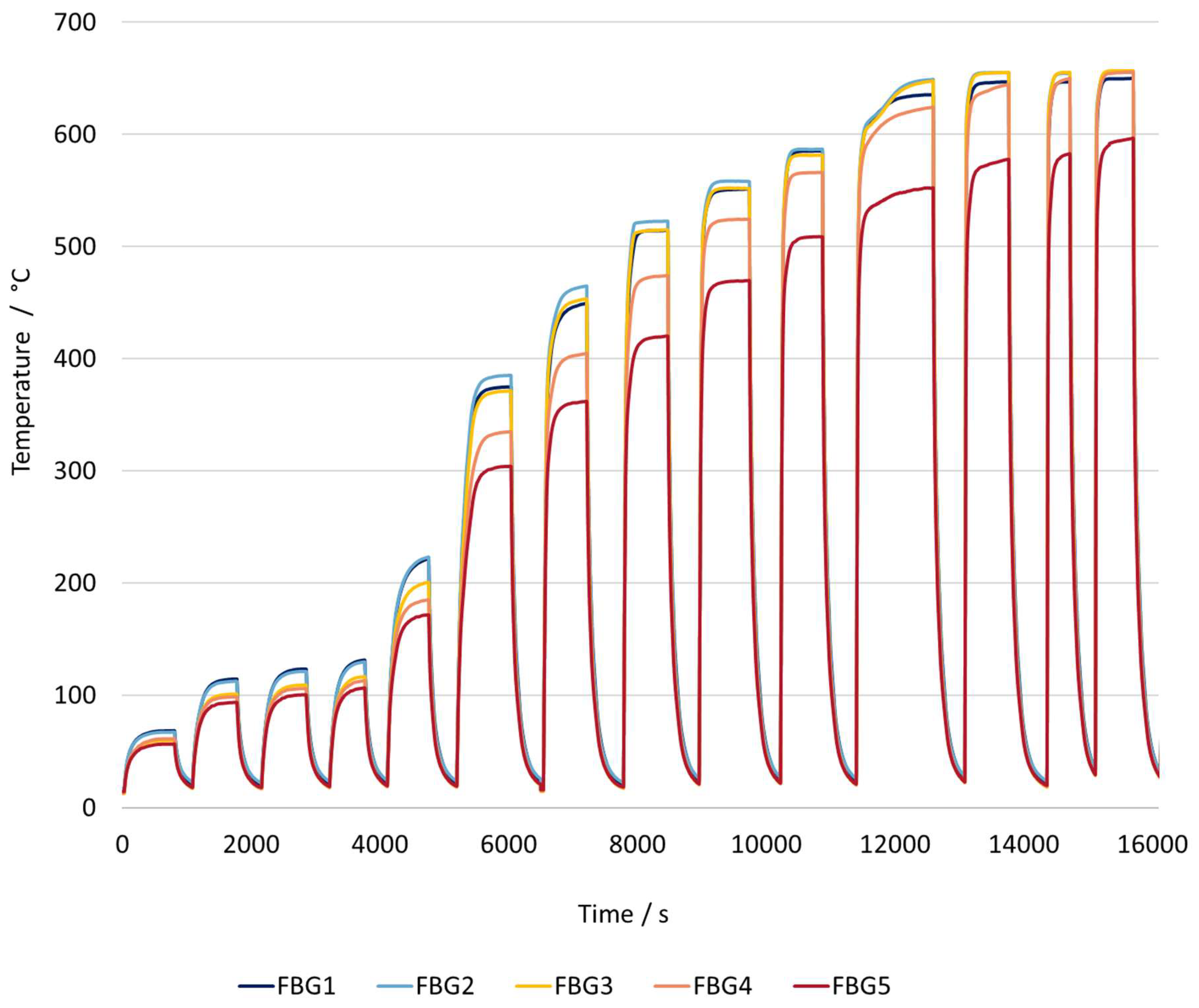
Figure 9.
Temperature profile inside the induction heating reactor(left axis) and MS signal for ammonia with just the Ni/Al2O3 (~ 65% Ni) catalyst heat source. FBG 1 is the measurement point closer to the outlet of the reactor and FBG 5 is the measurement point closer to the inlet of the reactor.
Figure 9.
Temperature profile inside the induction heating reactor(left axis) and MS signal for ammonia with just the Ni/Al2O3 (~ 65% Ni) catalyst heat source. FBG 1 is the measurement point closer to the outlet of the reactor and FBG 5 is the measurement point closer to the inlet of the reactor.
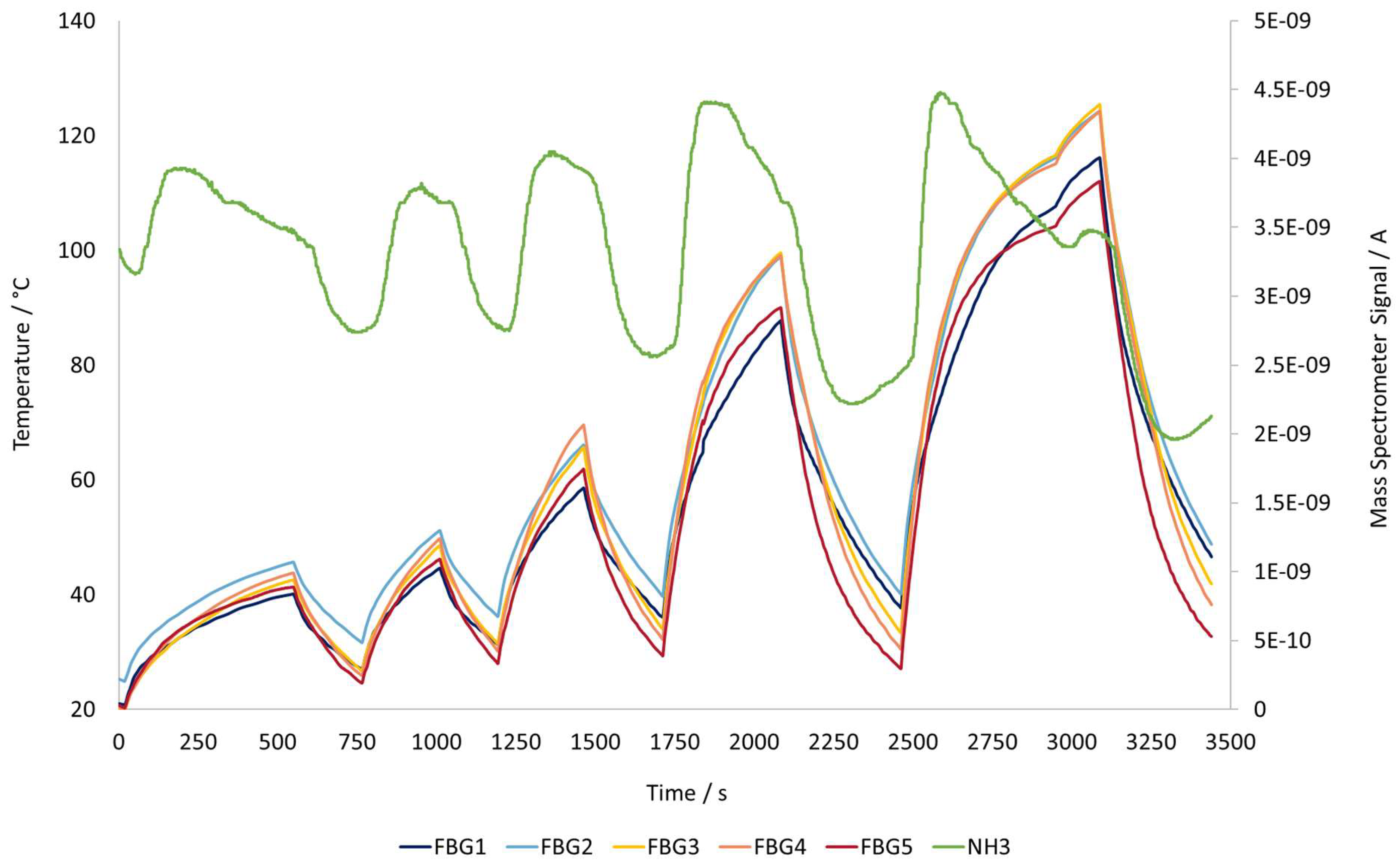
Figure 10.
Temperature profile inside the induction heating reactor with both the workpiece and catalyst as heat source. FBG 1 is the measurement point closer to the outlet of the reactor and FBG 5 is the measurement point closer to the inlet of the reactor.
Figure 10.
Temperature profile inside the induction heating reactor with both the workpiece and catalyst as heat source. FBG 1 is the measurement point closer to the outlet of the reactor and FBG 5 is the measurement point closer to the inlet of the reactor.
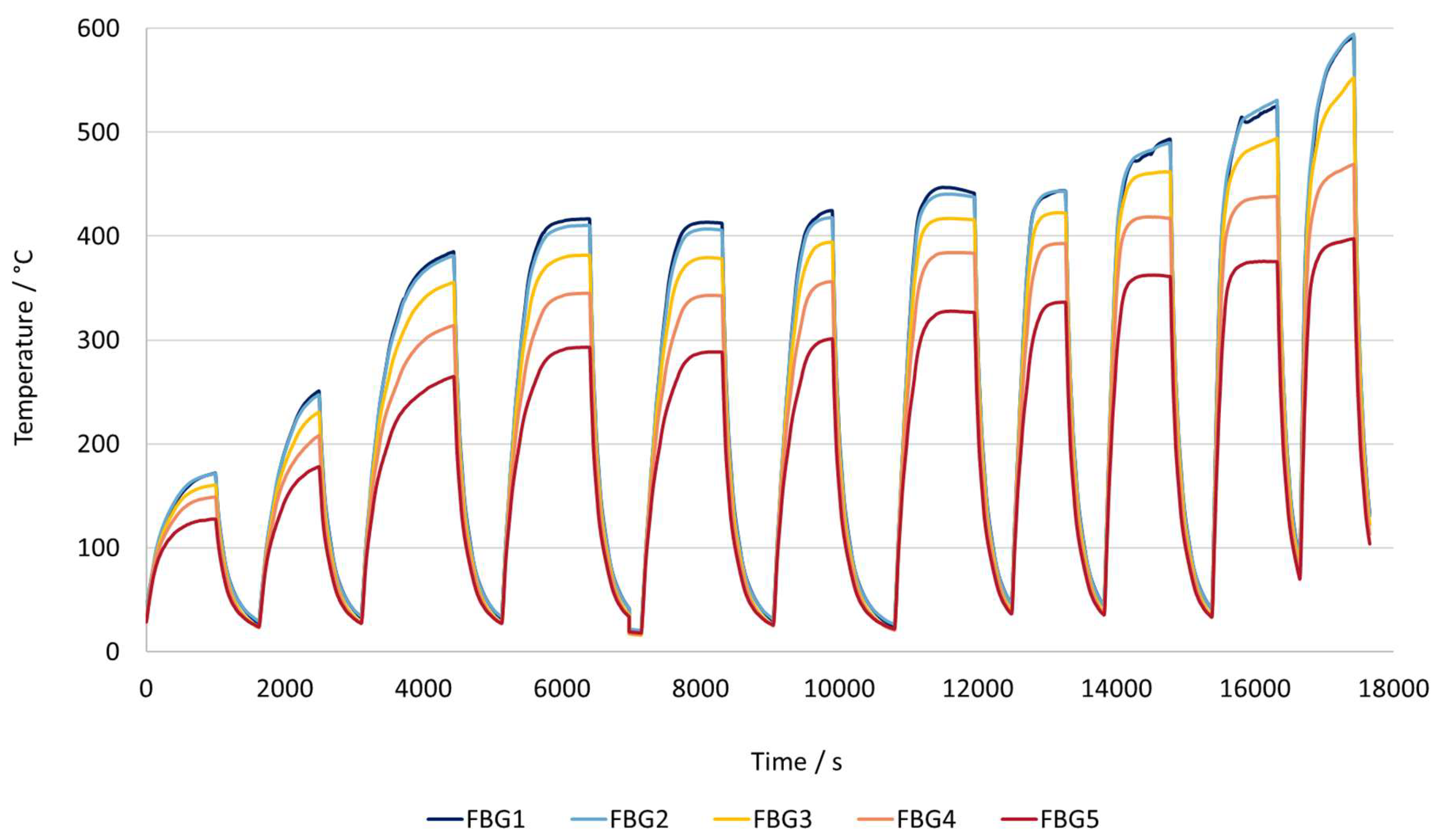
Figure 11.
Mass spectrometer signals of the components present in the gas leaving the reactor.
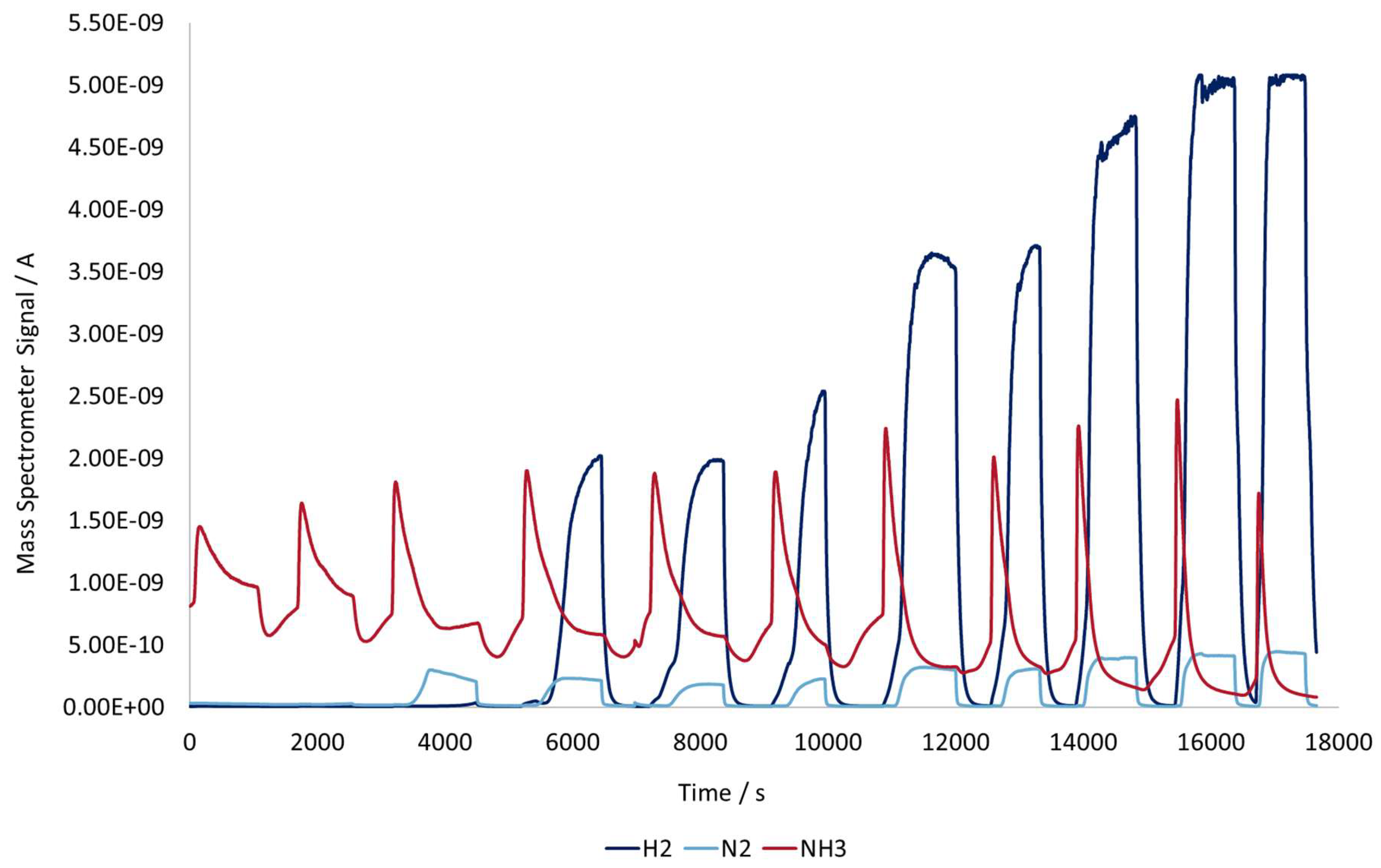
Figure 12.
Ammonia conversion curve as a function of the outlet gas temperature for induction heating reactor with the catalyst and workpiece compared to the conversion curve of the electric tube furnace and the theoretical equilibrium curve of the ammonia cracking reaction.
Figure 12.
Ammonia conversion curve as a function of the outlet gas temperature for induction heating reactor with the catalyst and workpiece compared to the conversion curve of the electric tube furnace and the theoretical equilibrium curve of the ammonia cracking reaction.
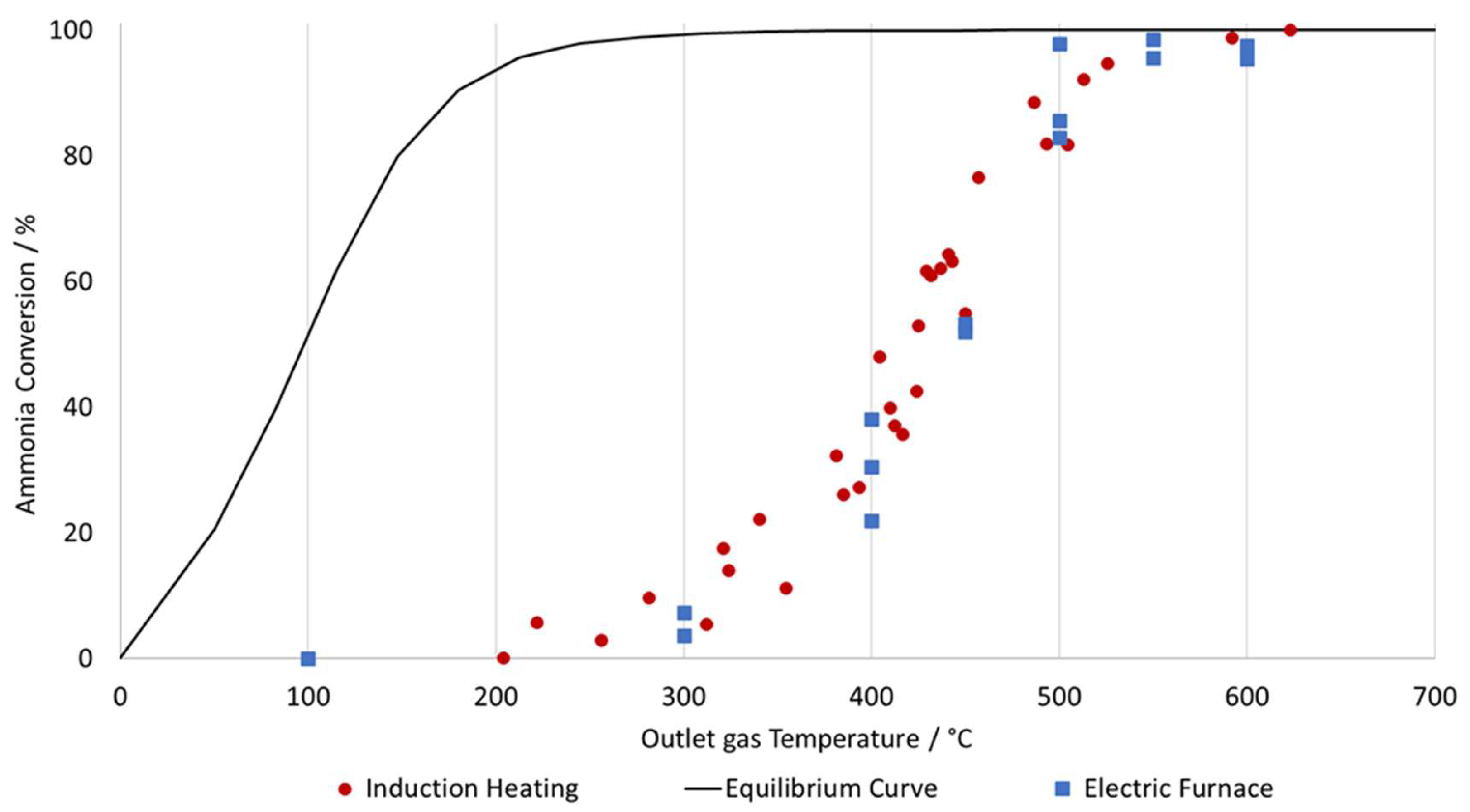
Figure 13.
Images captured with scanning electron microscopy(left) and Energy Dispersive X-ray Spectroscopy(right) containing the color-coded elemental maps indicating the presence of various elements. The top 2 pictures refer to the unused workpiece and the bottom 2 pictures refer to the workpiece after all of the experiments have been completed.
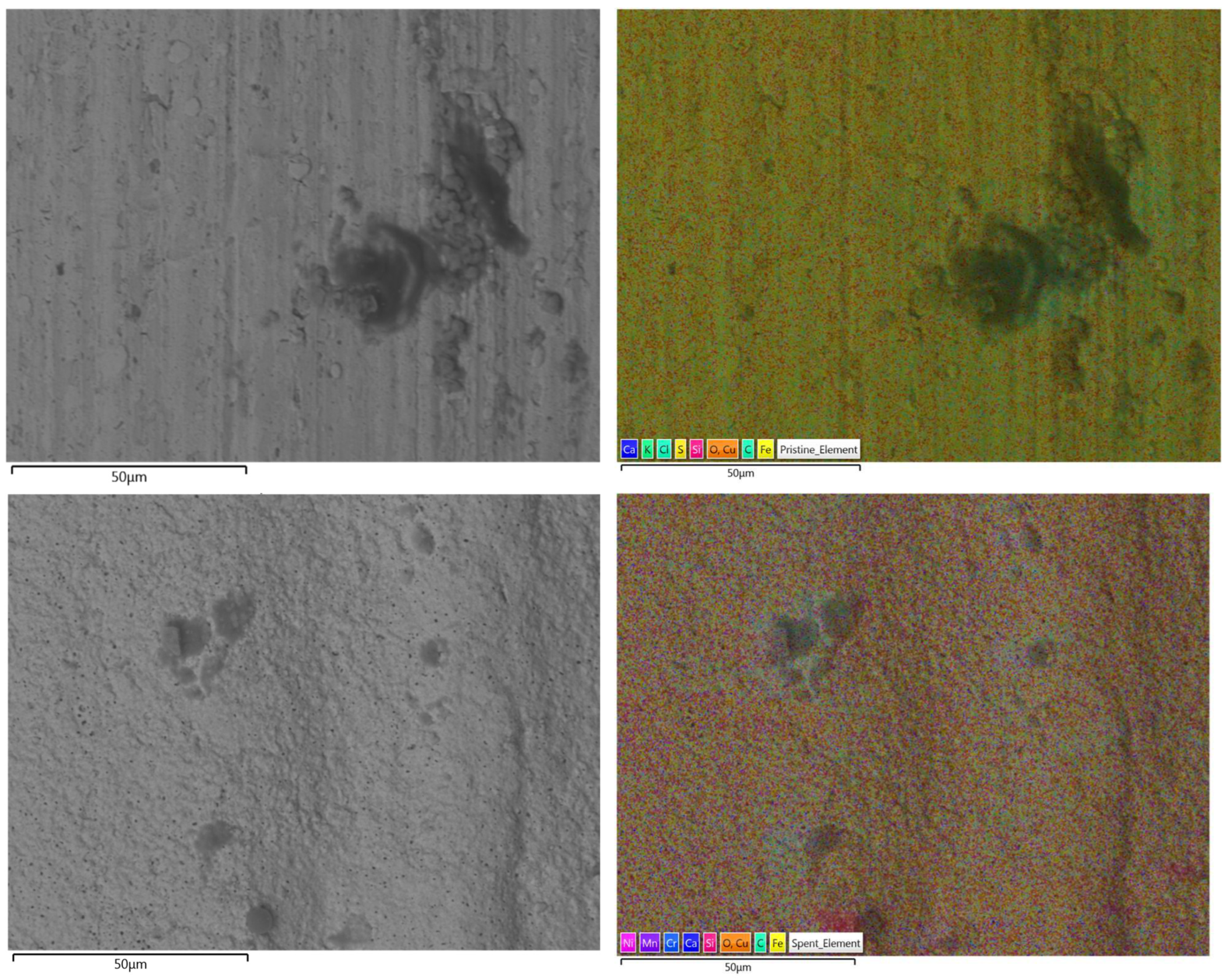

Table 1.
values related to the composition of the surface for both used and unused workpieces.
| Element | Unused Workpiece | Used Workpiece |
|---|---|---|
| Fe | 38.7 | 87.7 |
| Cu | 51.0 | 4.6 |
| C | 6.7 | 4.6 |
| O | 3.2 | 1.4 |
| Ni | – | 0.8 |
| Mn | – | 0.4 |
| Si | 0.1 | 0.3 |
| Cr | – | 0.2 |
Disclaimer/Publisher’s Note: The statements, opinions and data contained in all publications are solely those of the individual author(s) and contributor(s) and not of MDPI and/or the editor(s). MDPI and/or the editor(s) disclaim responsibility for any injury to people or property resulting from any ideas, methods, instructions or products referred to in the content. |
© 2025 by the authors. Licensee MDPI, Basel, Switzerland. This article is an open access article distributed under the terms and conditions of the Creative Commons Attribution (CC BY) license (http://creativecommons.org/licenses/by/4.0/).
Copyright: This open access article is published under a Creative Commons CC BY 4.0 license, which permit the free download, distribution, and reuse, provided that the author and preprint are cited in any reuse.


