

Submitted:
27 September 2025
Posted:
30 September 2025
You are already at the latest version
Abstract
We propose a novel optical method for performing integer division N ÷ D, based on the superposition of two transmissive masks: a dividend mask (G1) encoding N lines, and a completer mask (G2) providing blocks of D sites. The combined pattern is read in blocks, yielding quotient q and remainder r directly. This Interlaced Line Divider (ILD) provides a hardware-level analog computation of Euclidean division, with potential applications in cryptography, optical sensing, and unconventional computing.
Keywords:
optical computing
; integer division
; analog arithmetic
; spatial masks
; Euclidean division
; modular arithmetic
1. Introduction
Optical computing has a long history of implementing arithmetic operations through interference and diffraction [1]. Here we present the theoretical framework for a new optical scheme capable of directly performing integer division and remainder extraction. The method, which we call the Interlaced Line Divider (ILD), is based on the alignment of two masks of parallel lines.
This work provides a complete mathematical analysis of the ILD concept, demonstrating its theoretical correctness and establishing the physical conditions under which optical superposition can implement Euclidean division. We derive the fundamental relationship between optical transmission and discrete arithmetic operations, analyze robustness to fabrication tolerances and noise, and outline the experimental requirements for future laboratory implementation. The theoretical foundation presented here opens new possibilities for hardware-level analog computation of modular arithmetic, with potential applications in cryptography, optical sensing, and unconventional computing architectures.
2. Concept and Method
The ILD relies on a simple but instrumental idea: represent the dividend and divisor geometrically as line masks, and let optical superposition and blockwise detection perform the Euclidean division operation. Two complementary masks are employed, each encoding different aspects of the problem. This approach builds on established principles of spatial light processing [7,8] and mask-based optical computation [9].
2.1. Dividend and Completer Masks
- G1 (dividend mask): encodes the integer N by means of N opaque lines, equally spaced with pitch p.
- G2 (completer mask): defines the divisor D by imposing periodic block boundaries, each block containing D sites, and extending the grid up to the next multiple of D.
When the two masks are superposed, the optical field is segmented into blocks of width , each acting as a counting bin. A segmented detector placed after the masks integrates transmission over each block and reports the number of fully filled blocks (q) and the residual occupancy (r). In other words, the ILD physically implements the Euclidean division rule:
2.2. Illustrative Example
To see how the ILD reproduces Euclidean division in practice, consider the case of dividing by . The process unfolds as follows:
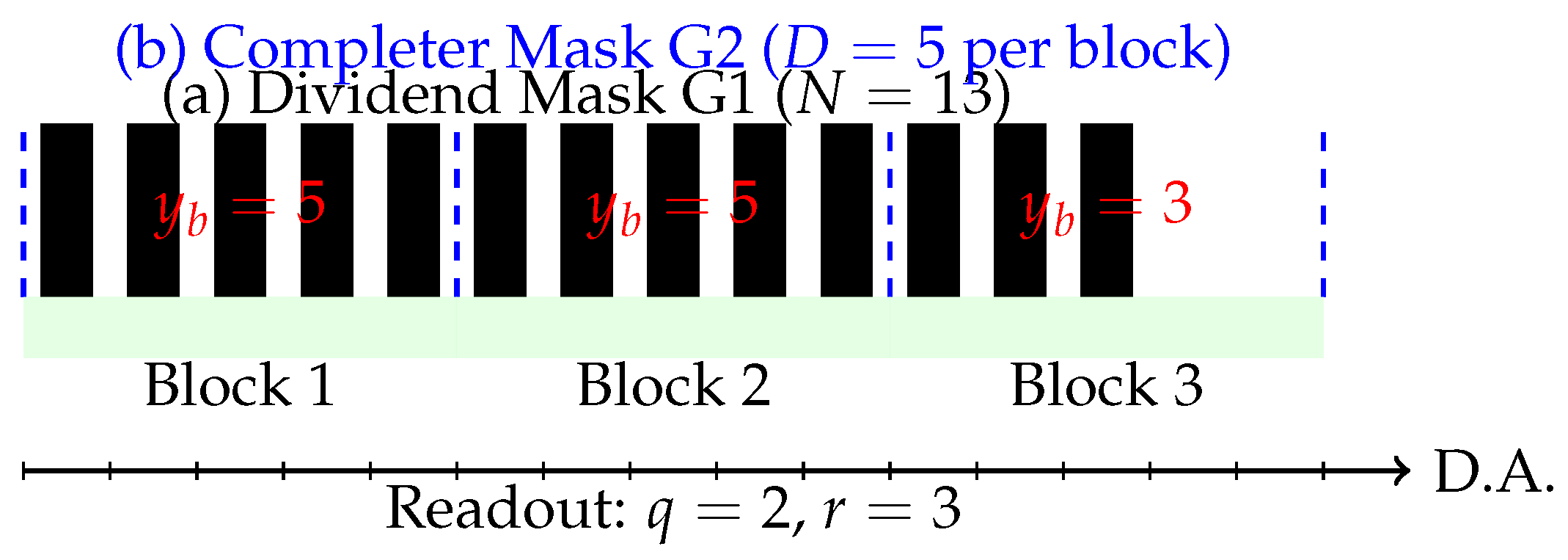
- Dividend mask (G1). Mask G1 encodes the integer by means of 13 opaque vertical lines, equally spaced with pitch p.
- Completer mask (G2). Mask G2 partitions the axis into blocks of size , so that the first block covers sites 1–5, the second block 6–10, and the third block 11–15. In total, G2 defines 15 sites grouped into three blocks.
-
Superposition. Overlaying G1 and G2, the detector now sees how the 13 lines of G1 distribute across the three blocks.
- Block 1 (sites 1–5): all five sites are filled.
- Block 2 (sites 6–10): all five sites are filled.
- Block 3 (sites 11–15): only three sites are filled (lines 11, 12, 13).
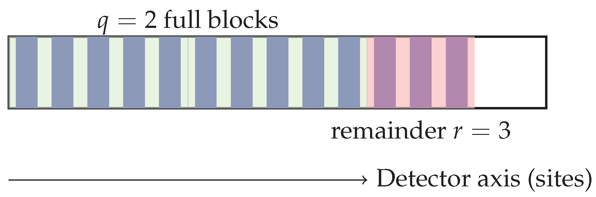
- Detector readout. The segmented detector integrates light per block. It registers two full blocks, corresponding to a quotient , and a partial block with three filled sites, giving the remainder .
In other words, the ILD reproduces the standard Euclidean division relation
but does so physically by line counting and block segmentation rather than by digital arithmetic.
Figure 1.
Example of ILD operation: , . Two full blocks () and a residual remainder of .
3. Mathematical Formalism and Correctness
We give a rigorous derivation of why the Interlaced Line Divider (ILD) returns the Euclidean division result , and we state the optical conditions under which the physical device implements the same combinatorics.
3.1. Discrete Combinatorial Model (Ideal Counting)
Fix an integer block size and a pitch defining a one–dimensional lattice of sites The dividend mask encodes N opaque line elements at the first N sites, and is empty elsewhere. Let
Partition the lattice into contiguous blocks of size D:
and define the block occupancy (opaque count) of as
Lemma 1
(Euclidean partition by block sums). Let with and . Then the block occupancies satisfy
Proof.
For , , hence all D sites are occupied: . For , , hence . For , intersects in exactly sites, so . □
Corollary (ideal ILD readout). The quotient and remainder are read as
Thus the ideal block counting on alone reproduces Euclidean division.
Role of the completer mask .
Physically, provides registration and visualization of blocks: it defines the block boundaries and ensures that detection integrates over non-overlapping regions of width . Mathematically, induces the fixed partition used in (2); no further algebraic role is needed for correctness.
3.2. Optical Model (Amplitude Masks and Block Integrals)
We now link optical transmission and detection to the discrete counts .
Mask transmittances.
Model as an amplitude mask with transmittance
where is the line contrast and w is a site-localized aperture function supported in a guard-banded window , with . Let be a periodic block-window mask of period that defines non-overlapping regions of interest (ROIs) , e.g., , and (fully transmissive) over .
Illumination and detection.
Illumination is a uniform plane wave of intensity . For thin, absorption-dominant masks, the transmitted intensity is . Let the detector report the block integral
Assumption 1
(guard band and alignment). (i) iff . (ii) Mechanical misalignment ε satisfies , so each opaque element remains within its site window.
Let (site-wise opaque area). Under Assumption 1, each occupied site in contributes the same to the integral, and empty sites contribute 0.
Proposition 1
(affine link between optics and counts). Under Assumption 1,
Proof.
Equation (3) reduces to □
Consequences.
(i) is a strictly decreasing affine function of the integer count . (ii) Since , the set of possible values is a uniform lattice with spacing . (iii) Thresholding the block integrals at recovers which blocks are full () and which are not. The last nonzero block’s integral yields by inversion of (4).
Theorem 1
(Correctness of ILD optical readout). Under Assumption 1 and with contrast , the block integrals uniquely determine the block counts via (4), and hence return and . Therefore the ILD implements Euclidean division .
Proof.
Invert (4): . Because and , rounding to the nearest integer is exact in the noiseless setting. Lemma 1 then yields . □
3.3. Robustness to Small Misalignment and Noise
Geometric robustness.
If the lateral misalignment , each opaque element remains inside its site window, so the per-site contribution to remains . Thus (4) holds exactly.
Photometric robustness.
With additive noise on each block integral, , integer recovery is guaranteed if for all b, since adjacent lattice points are separated by . More generally, a maximum-likelihood (nearest-lattice) decoder on recovers with error probability decaying with SNR.
Gray-level transmittance.
If lines have transmittance instead of 0, replace by in (4). The same lattice structure and decoding apply.
3.4. Superposition and Moiré Variants (Optional)
The analysis above used amplitude multiplication and ROI integration. In a moiré variant, two periodic line sets at a small relative angle create an envelope with period proportional to . If the ROI windows are placed to integrate one envelope period per block (calibrated once), the same affine link (4) is obtained at the envelope scale, with effective set by the envelope contrast. Thus the counting argument (Lemma 1) and Theorem 1 still apply.
Figure 2.
Schematic of the ILD principle for , . (a) The Dividend Mask G1 has opaque lines (black rectangles). (b) The Completer Mask G2 is fully transparent but defines three contiguous blocks (dashed blue lines), each of width . (c) Superposition of G1 and G2. A segmented detector (green regions) integrates light transmission over each block. Readout: Block 1 and Block 2 are fully opaque (), yielding . Block 3 has opaque lines. Blocks beyond the third are empty. Detector Axis: D.A.
Figure 2.
Schematic of the ILD principle for , . (a) The Dividend Mask G1 has opaque lines (black rectangles). (b) The Completer Mask G2 is fully transparent but defines three contiguous blocks (dashed blue lines), each of width . (c) Superposition of G1 and G2. A segmented detector (green regions) integrates light transmission over each block. Readout: Block 1 and Block 2 are fully opaque (), yielding . Block 3 has opaque lines. Blocks beyond the third are empty. Detector Axis: D.A.
3.5. Summary of Assumptions and Guarantees
The preceding analysis introduced several technical conditions to ensure that the optical implementation matches the combinatorial model. For clarity, we collect them here as explicit assumptions, each linked to the formal steps in Section 3:
- (A1)
- Site separability. Each line aperture fits entirely within a guard-banded window . This guarantees that every line is unambiguously assigned to a site.
- (A2)
- Block registration. The detector integrates over fixed regions of interest (ROIs) of width , aligned with the site grid. This ensures that block sums coincide with the mathematical partitions .
- (A3)
- Contrast and SNR. The per-site decrement in transmitted intensity is nonzero () and the additive noise is bounded by . This ensures that the lattice of possible block integrals is resolvable without overlap, so that integer recovery is unambiguous.
Taken together, (A1)–(A3) constitute the physical envelope under which the affine relation (4) holds. Within this envelope the ILD performs exact Euclidean division by block integration and nearest-lattice decoding, establishing the correctness of the method in both theory and practice.
Figure 3.
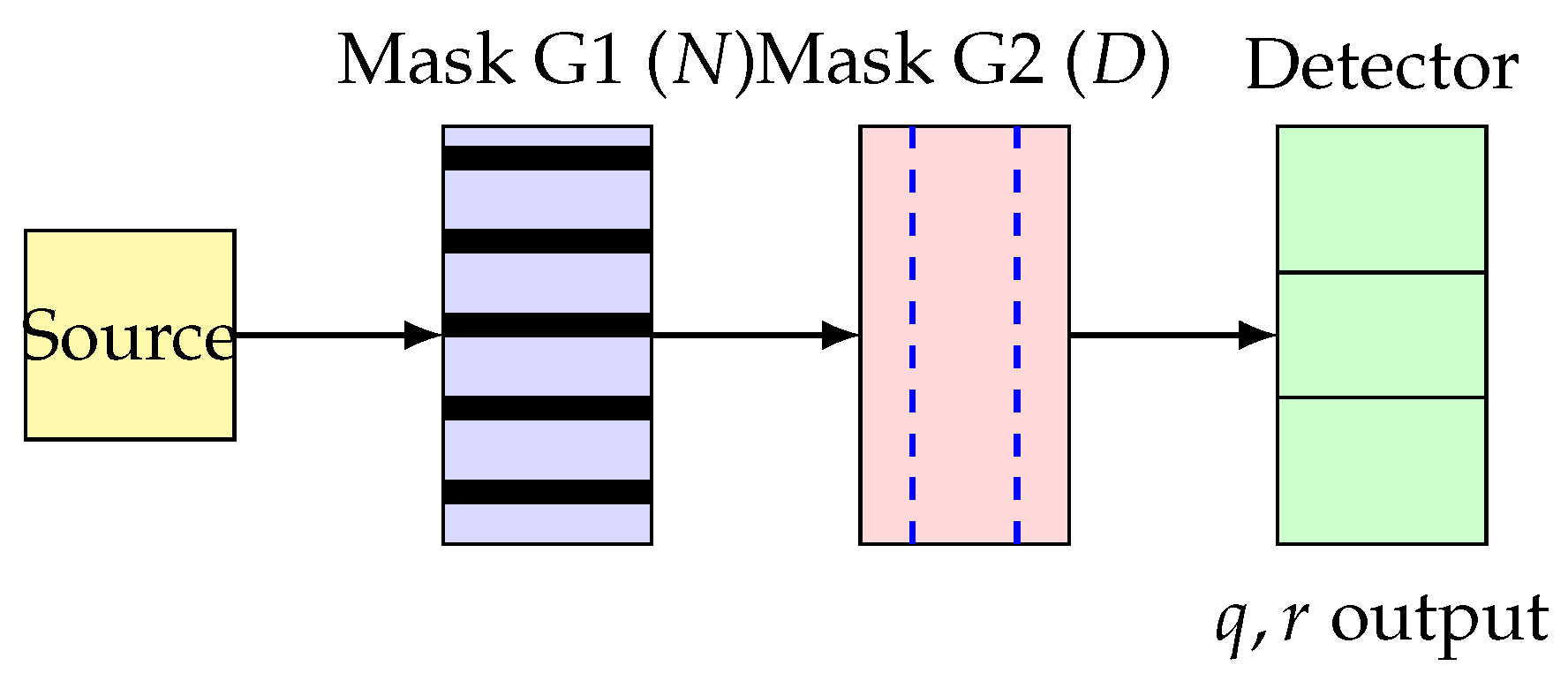
Optical schematic of the Interlaced Line Divider (ILD). Light from a source passes through the Dividend Mask G1 (encoding N lines), then through the Completer Mask G2 (block structure of size D), and is finally collected by a segmented detector. The detector integrates per block, yielding directly the quotient and remainder .
Figure 3.
Optical schematic of the Interlaced Line Divider (ILD). Light from a source passes through the Dividend Mask G1 (encoding N lines), then through the Completer Mask G2 (block structure of size D), and is finally collected by a segmented detector. The detector integrates per block, yielding directly the quotient and remainder .
3.6. Computational Complexity and Performance Analysis
3.6.1. Time Complexity
The ILD performs Euclidean division in constant time with respect to both dividend N and divisor D, since the optical computation occurs through simultaneous light transmission across all sites. This represents a fundamental advantage over sequential digital algorithms:
- Digital long division: bit operations [10]
- ILD optical method: - independent of operand size
The physical computation time is limited only by light transit time ( where L is the optical path length) and detector integration time, both typically on the order of nanoseconds to microseconds.
3.6.2. Parallelizability
Unlike sequential digital algorithms, the ILD exhibits massive intrinsic parallelism:
- Spatial parallelism: All N dividend lines are processed simultaneously through optical superposition.
- Block parallelism: Multiple divisions can be performed in parallel by replicating the mask structure. A single optical setup can compute M independent divisions simultaneously using spatially multiplexed regions.
- Wavelength parallelism: Different wavelengths can carry independent division problems through wavelength-division multiplexing, limited only by detector spectral resolution.
For comparison, digital division requires sequential steps even with optimal parallel hardware, while the ILD maintains complexity regardless of problem size.
3.6.3. Theoretical Throughput Analysis
Consider an ILD system with the following parameters:
- Detector integration time: s
- Mask switching time (for programmable operation): s
- Spatial multiplexing capacity: M parallel channels
- Wavelength multiplexing capacity: channels
The theoretical throughput is:
For a practical implementation with spatial channels, wavelengths, and the parameters above:
This represents a significant advantage for applications requiring high-throughput modular arithmetic, such as cryptographic operations or large-scale numerical simulations.
3.6.4. Scaling Properties
The optical approach exhibits favorable scaling properties:
- Operand size independence: Computation time remains constant as N and D increase, unlike digital methods where complexity grows with operand bit length.
- Energy scaling: Power consumption scales primarily with illumination requirements and detector count, not with operand magnitude.
- Physical scaling: The mask area scales linearly with maximum operand size, providing a predictable trade-off between physical footprint and computational range.
These properties make the ILD particularly attractive for specialized applications where division operations dominate computational cost, such as real-time digital signal processing or high-frequency trading systems requiring rapid modular arithmetic.
3.7. Physical Limits and Fundamental Constraints
3.7.1. Diffraction-Limited Resolution
The spatial resolution of the ILD is fundamentally constrained by optical diffraction. For coherent illumination with wavelength , the minimum resolvable feature size is approximately:
where NA is the numerical aperture of the optical system. This sets a lower bound on the achievable pitch p, and hence the maximum operand density. For visible light ( nm) and moderate NA :
This diffraction limit constrains the maximum dividend for a given physical aperture L: . Beyond this limit, adjacent line elements become unresolvable, violating Assumption (A1).
3.7.2. Shot Noise and Fundamental Detection Limits
The ultimate sensitivity is limited by photon shot noise in the detector. For a block receiving photons, the signal-to-noise ratio is:
From Equation (4), reliable discrimination between adjacent lattice points requires , yielding a minimum photon budget:
This establishes a fundamental trade-off between speed (integration time), power (illumination intensity), and accuracy in the quantum-limited regime.
3.7.3. Connection to Analog Computing Principles
The ILD exemplifies several fundamental principles of analog computation:
- Spatial encoding: Information is represented through physical spatial arrangements rather than temporal sequences, enabling massive parallelism inherent to wave phenomena.
- Linear superposition: The optical field obeys Maxwell’s equations, whose linearity allows simultaneous processing of multiple spatial channels without cross-talk (within the paraxial approximation).
- Physical constraint satisfaction: The block integration naturally implements the constraint , ensuring consistency through physical conservation rather than algorithmic verification.
- Analog-to-digital conversion: The detector performs inherent quantization through photon counting, bridging continuous optical fields to discrete arithmetic results.
These principles, first articulated in early analog computer theory [13,14], remain relevant for modern optical processors [15].
These principles distinguish optical analog computers from digital architectures, where information processing occurs through sequential logical operations rather than physical field evolution.
3.7.4. Theoretical Extensions
2D Array Generalization. The ILD concept extends naturally to two-dimensional arrays for simultaneous processing of multiple operands. Consider a 2D mask encoding dividends along orthogonal rows, with a corresponding completer mask defining block structures. A 2D detector array can then compute for all rows simultaneously, providing complexity for batch division operations.
This extension follows established approaches in parallel optical processors [19] and systolic array architectures [20].
Multi-radix Systems. The blocking scheme generalizes to non-uniform block sizes , enabling mixed-radix number representations. This allows computation of simultaneous divisions by different bases: , , etc., relevant for applications in digital signal processing and number-theoretic transforms.
Cascaded Operations. Multiple ILD stages can be cascaded to implement more complex operations. For instance, computing requires two stages: first compute , then . The cascaded architecture maintains complexity while extending computational capability.
Continuous-Variable Extensions. For non-integer operands, the line discretization can be replaced by continuous transmittance profiles , where rect is the rectangular function. Block integration then computes continuously, useful for analog signal processing applications.
These extensions demonstrate that the ILD represents not merely an isolated arithmetic unit, but a foundational element in a broader class of spatial optical computers based on mask superposition and blockwise detection.
4. Experimental Realization
Having established the mathematical formalism and demonstrated the principle of operation of the Interlaced Line Divider (ILD), we now turn to a possible laboratory implementation. The goal is to identify a minimal optical setup that is consistent with the theoretical assumptions of Section 3 while being feasible with standard photonics components. In what follows, we outline the source, masks, and detector specifications required for a first prototype.
4.1. Optical Setup
A minimal experimental configuration for the ILD can be assembled using standard benchtop photonics components. The key requirements are a coherent or quasi-coherent source, two masks that encode the dividend and divisor, and a detector capable of blockwise integration. One possible implementation is as follows:
- Source: LED or low-power laser in the 520–650 nm range, chosen for ease of alignment and compatibility with inexpensive detectors.
- Masks: chrome-on-glass gratings with pitch –m and linewidth 30–m. These values ensure that individual sites are resolvable by the detector while remaining within standard photolithography tolerances.
- Detector: CMOS/CCD with software-defined regions of interest or, alternatively, a segmented photodiode array. Segmentation allows direct blockwise integration of transmitted intensity, consistent with the formalism in Section 3.
4.2. Tolerances
The analytical model in Section 3 assumes that each opaque line fits entirely within its designated site window and that block boundaries are correctly registered. In practice, this requires fabrication and alignment tolerances to be tighter than the guard bands introduced in Assumption 1. Specifically:
- Pitch tolerance: Variations in the site pitch must be smaller than m within a block to avoid cumulative drift that would push a line outside its guard band.
- Block registration: Errors in defining the block boundaries must be to ensure that all D sites intended for a block are correctly integrated by the detector.
- Alignment: The relative position of masks G1 and G2 is maintained with an XY translation stage so that the partitioning of sites into blocks remains stable during measurement.
These tolerances guarantee that the affine relation (4) between optical block integrals and discrete site counts remains valid in the physical device, ensuring error-free recovery of the quotient and remainder.
4.3. Quantitative Application Analysis
The ILD’s unique combination of complexity, massive parallelism, and hardware-level implementation creates specific niches where it outperforms conventional approaches. We analyze key application domains with theoretical performance estimates.
4.3.1. Cryptographic Co-processing
Advantage Analysis: RSA decryption requires computing where modular reduction dominates computational cost. For 2048-bit RSA, approximately 60% of execution time involves modular arithmetic operations. Following standard analysis of RSA computational costs [16], modular exponentiation dominates the runtime.
Performance Estimate: Consider batch processing of RSA operations with 256-bit moduli. Digital implementation using Montgomery reduction requires cycles per operation at 3 GHz, yielding:
The ILD with spatial multiplexing ( channels) and Equation (6) parameters achieves:
Speedup Factor: for batch operations, with additional benefits in power consumption due to analog processing.
Optimal Regime: Most advantageous for applications requiring high-throughput modular arithmetic with moderate precision (8-16 bits), such as elliptic curve operations or lattice-based post-quantum cryptography.
4.3.2. Real-time Digital Signal Processing
Use Case: Fast Fourier Transform (FFT) implementations often require modular reduction for number-theoretic transforms, particularly in finite field arithmetic.
Performance Analysis: A 1024-point FFT over requires modular operations. At video frame rates (60 fps), this demands reductions per second.
ILD Implementation: Using 16 parallel channels (one per bit), the ILD can process each reduction in s (equation 6), easily meeting real-time constraints while digital implementations struggle with this throughput.
Competitive Advantage: The optical approach excels when:
- Division latency must be deterministic (no data-dependent timing)
- Multiple simultaneous divisions required
- Power budget constraints favor analog computation
4.3.3. Monte Carlo Simulations
Application Domain: Large-scale simulations requiring random number generation with specific modular properties.
Scaling Analysis: Linear congruential generators require computing millions of times. For samples with :
- Digital approach: sequential operations at cycles each = 3.3 seconds at 3 GHz - ILD approach: Batch processing 1000 samples simultaneously = batch operations × 10 s = 10 seconds
Trade-off Analysis: Digital wins for sequential processing, but ILD becomes advantageous when: 1. Multiple independent streams needed simultaneously 2. Custom moduli required (where hardware optimizations don’t apply) 3. Energy efficiency is critical
4.3.4. Optical vs Digital Performance Boundaries
The ILD outperforms digital approaches when:
- Operand Size: 8-64 bits (sweet spot: 16-32 bits) - Below 8 bits: Digital lookup tables are faster - Above 64 bits: Precision limits dominate
- Batch Size: simultaneous operations - Spatial parallelism overcomes digital SIMD advantages
- Power Constraints: mW per operation - Optical computation can be more energy-efficient than digital arithmetic units
- Latency Requirements: s deterministic - No branch prediction or cache misses
4.3.5. System Integration Considerations
Hybrid Architectures: The ILD functions best as a specialized co-processor in hybrid systems:
where s for mask configuration. This overhead is amortized over large batch sizes, making the approach most suitable for applications with: - High computational density (many operations per setup) - Predictable operation patterns (allowing mask pre-configuration) - Tolerance for analog precision limits ( relative accuracy)
Market Positioning: The ILD targets specialized niches rather than general-purpose arithmetic: 1. Cryptographic accelerators for IoT devices with power constraints 2. DSP co-processors for radar/communications requiring deterministic timing 3. Scientific computing nodes for embarrassingly parallel modular arithmetic 4. Edge AI inference engines using quantized neural networks with modular activations
These applications justify the additional complexity of optical implementation through substantial performance gains in specific operational regimes.
5. Applications
Beyond its pedagogical appeal, the ILD can serve as a physical primitive for modular arithmetic and blockwise aggregation in optics. Prior work on optical and analog computing has shown that simple optical elements can implement useful linear and nonlinear transforms with low latency and massive parallelism [2,3], while recent developments in photonic hardware for AI underscore the practical value of moving arithmetic into the optical domain [4,5]. Programmable or mask-based implementations (including SLMs) provide an established route to realize such primitives in compact benchtop systems [6].
- Optical co-processors. Because the ILD directly executes and at the physical layer, it can act as a building block for optical arithmetic accelerators. In integrated photonic circuits, ILD modules could be cascaded with other operators (Fourier lenses, correlators, nonlinear media) to perform more complex pipelines with minimal energy cost.
- Cryptography. Modular reduction is central to cryptosystems such as RSA, ECC, and lattice-based schemes. An ILD stage can serve as a dedicated hardware co-processor that computes optically, offloading a costly digital operation. Furthermore, the remainder block encodes a residual pattern sensitive to fabrication imperfections and alignment noise. This naturally implements a physical unclonable function (PUF): each device has a unique optical signature, which can be leveraged for authentication and secure key storage.
- Optical sensing and encoders. Mounting ILD masks on a rotating or translating platform converts the quotient q and remainder r into signals that vary with angle or displacement. The remainder r, in particular, is highly sensitive to sub-micron misalignments, making it a potential probe for strain, thermal expansion, or micro-displacement detection. Compared with conventional optical encoders, the presence of a remainder channel increases information density and resolution.
- Unconventional and neuromorphic computing. - Unconventional and neuromorphic computing. Following recent work on optical neural networks [21,22], the ILD can be embedded as a primitive inside hybrid photonic–electronic systems, providing fast non-linear operations that resemble spiking or thresholding.
- Educational tools. The ILD offers a tangible, visual demonstration of Euclidean division: learners directly observe q as the number of full blocks and r as the leftover lines. With its simple setup (light source, two masks, detector), it is well suited for instructional labs in optics, information processing, and computer science.
6. Conclusion
We introduced the ILD, a simple yet powerful optical scheme to implement Euclidean division using interlaced line masks. Future work includes fabrication of prototypes, extension to 2D grids, and hybrid integration with spatial light modulators for programmable arithmetic.
Author Contributions
The original contributions presented in this study are included in the article/supplementary material. Further inquiries can be directed to the corresponding author(s).
Funding
This research received no external funding.
Institutional Review Board Statement
Not applicable.
Informed Consent Statement
Not applicable
Data Availability Statement
Data is contained within the article or supplementary material.
Conflicts of Interest
The authors declare no conflicts of interest.
References
- J. W. Goodman, Introduction to Fourier Optics, 2nd ed., McGraw-Hill, 1996.
- R. A. Athale and J. N. Lee, “Optical processing using outer-product concepts,” Proceedings of the IEEE, vol. 72, no. 7, pp. 931–941, July 1984. [CrossRef]
- H. J. Caulfield, “Space-time complexity in optical computing,” Multidimensional Systems and Signal Processing, vol. 2, pp. 373–378, Nov. 1991. [CrossRef]
- B. J. Shastri, A. N. Tait, T. F. de Lima, W. H. P. Pernice, H. Bhaskaran, C. D. Wright, and P. R. Prucnal, “Photonics for artificial intelligence and neuromorphic computing,” Nature Photonics, vol. 15, pp. 102–114, Jan. 2021. [CrossRef]
- Y. Shen, N. C. Harris, S. Skirlo, M. Prabhu, T. Baehr-Jones, M. Hochberg, X. Sun, S. Zhao, H. Larochelle, D. Englund, and M. Soljačić, “Deep learning with coherent nanophotonic circuits,” Nature Photonics, vol. 11, pp. 441–446, July 2017. [CrossRef]
- B. Javidi and Q. Tang, “Hybrid implementation of nonlinear joint-transform correlator,” in OSA Annual Meeting, Technical Digest Series (Optica Publishing Group, Boston, MA, Nov. 1990), paper WW5. [CrossRef]
- A. Vanderlugt, "Optical Signal Processing," Wiley, New York, 1992.
- J. Shamir, "Optical Systems and Processes," SPIE Press, Bellingham, WA, 1999.
- D. Casasent, "Optical data processing," in Handbook of Optics, M. Bass, Ed., McGraw-Hill, New York, 1995, vol. II, ch. 23.
- D. E. Knuth, "The Art of Computer Programming, Volume 2: Seminumerical Algorithms," 3rd ed., Addison-Wesley, Reading, MA, 1997.
- R. P. Brent and P. Zimmermann, "Modern Computer Arithmetic," Cambridge University Press, Cambridge, 2010.
- P. D. Barrett, "Implementing the Rivest Shamir and Adleman public key encryption algorithm on a standard digital signal processor," in Advances in Cryptology — CRYPTO ’86, Springer, Berlin, 1987, pp. 311–323.
- V. Bush, "The differential analyzer. A new machine for solving differential equations," Journal of the Franklin Institute, vol. 212, pp. 447–488, 1931.
- C. Mead, "Analog VLSI and Neural Systems," Addison-Wesley, Reading, MA, 1989.
- D. A. B. Miller, "Are optical transistors the logical next step?" Nature Photonics, vol. 4, pp. 3–5, 2010.
- A. J. Menezes, P. C. van Oorschot, and S. A. Vanstone, "Handbook of Applied Cryptography," CRC Press, Boca Raton, FL, 1996.
- X. Xie, X. Huang, L. Sun, and S. Han, "FPGA design and implementation of large integer multiplier," Journal of Electronics & Information Technology, vol. 41, no. 8, pp. 1855–1860, 2019. [CrossRef]
- C. Paar, J. Pelzl, and T. Güneysu, "Understanding Cryptography: From Established Symmetric and Asymmetric Ciphers to Post-Quantum Algorithms," Textbook, Springer, Cham, 2024.
- A. Huang, "Optical Digital Computers: Devices and Architecture," in Concurrent Computations, S. K. Tewksbury, B. W. Dickinson, and S. C. Schwartz, Eds., Springer, Boston, MA, 1988, pp. 49–72.
- H. T. Kung and C. E. Leiserson, "Systolic arrays for (VLSI)," in Introduction to VLSI Systems, Addison-Wesley, Reading, MA, 1980.
- X. Lin, Y. Rivenson, N. T. Yardimci, M. Veli, Y. Luo, M. Jarrahi, and A. Ozcan, "All-optical machine learning using diffractive deep neural networks," Science, vol. 361, pp. 1004–1008, 2018.
- J. Feldmann, N. Youngblood, M. Karpov, H. Gehring, X. Li, M. Stöhr, D. Schmid, M. J. Kull, Y. F. Xiao, D. L. Elder, M. H. Pfeiffer, T. J. Kippenberg, W. H. P. Pernice, C. D. Wright, H. Bhaskaran, and P. Marin-Palomo, "Parallel convolutional processing using an integrated photonic tensor core," Nature, vol. 589, pp. 52–58, 2021.
Disclaimer/Publisher’s Note: The statements, opinions and data contained in all publications are solely those of the individual author(s) and contributor(s) and not of MDPI and/or the editor(s). MDPI and/or the editor(s) disclaim responsibility for any injury to people or property resulting from any ideas, methods, instructions or products referred to in the content. |
© 2025 by the authors. Licensee MDPI, Basel, Switzerland. This article is an open access article distributed under the terms and conditions of the Creative Commons Attribution (CC BY) license (http://creativecommons.org/licenses/by/4.0/).
Copyright: This open access article is published under a Creative Commons CC BY 4.0 license, which permit the free download, distribution, and reuse, provided that the author and preprint are cited in any reuse.