Preprint
Article

This version is not peer-reviewed.

Numerical Simulation of Microwave Heating of High-Energy Radio-Absorbing Composites

Submitted:

21 September 2025

Posted:

26 September 2025

You are already at the latest version

Abstract

This study presents a novel approach to analyzing high-energy radio-absorbing composites (HRCs) by combining computational modeling and experimental measurements of temperature field distribution under microwave irradiation using a waveguide-based setup. Unlike previous studies that mainly focus on nanofillers or bulk dielectric properties, our work investigates the thermal response of a composite with a single macroscopic SiC sphere (d = 20mm), embedded in epoxy resin (ED-20) and fluoroplastic (PTFE) matrices, both as an individual sphere and in grouped configurations. This setup enables direct observation and modeling of localized heat accumulation and dissipation pathways. Temperature distributions were examined in filler and at a boundary of filler-matrix at various distances from the filler–matrix interface under different power levels and thermal boundary conditions in ED-20 and PTFE. The results demonstrate that the ED-20 matrix with a 20mm SiC filler offers an optimal balance between microwave energy absorption and thermal stability. However, at power inputs above 400W and heating rates exceeding 10°C/s, signs of thermal degradation and matrix damage were observed. These findings provide new insights for the design of thermally robust, structurally optimized HRCs with tunable electromagnetic performance.

Keywords: 
;  ;  ;  ;  ;  

1. Introduction

At present, for technological processes of acceleration, destruction, deformation there is a need to obtain materials with predictable functional properties that can be controlled by external influence [1,2,3,4]. Therefore, a present-day task is to develop new high-energy composites and technology of electrophysical influence on them to initiate functional activity associated with the release of energy. Such materials include a new class of high-energy radio-absorbing composites (HRCs) which combine the properties of radio-absorbing and high-energy materials [5,6,7,8,9,10].
Usually, radio-absorbing materials consist of an organic or inorganic matrix which contains an absorbing component in the form of powder, fibers, nano- and micro-fillers. Numerous studies have explored microwave-absorbing polymer composites using nanostructured fillers such as carbon nanotubes, graphene, and ferrite nanoparticles, which offer uniform absorption and lightweight structures [11,12,13,14,15,16,17,18,19,20,21,22,23,24]. However, these approaches often lack the ability to control localized heating and temperature gradients within the material bulk. Additionally, most experimental setups rely on thin-film geometries, making it difficult to analyze heat transfer behavior in larger volumes [25,26,27,28,29].
All known radio-absorbing materials can be divided into two large groups: applied materials (radio-absorbing coatings) and structural bulk materials [30]. Modern radio-absorbing materials are an integral part of devices and equipment in radio and electronic engineering, in particular, ultra-high frequency systems [31,32,33,34,35]. They have also found wide application in electromagnetic compatibility, protection from electromagnetic effects on biological objects, protection of radio electronic equipment [25,36,37,38]. The materials have good radio-absorbing properties only under certain conditions of external influence (temperature, frequency, etc.) [39]. Currently available radio-absorbing materials are capable of interacting with electromagnetic radiation and converting it into heat. The effect of a high-power electromagnetic radiation source on a radio-absorbing material leads to its heating. As a result, significant thermal stresses arise at the binder/filler boundary, which can lead to partial or complete destruction of the material. Destruction of radio-absorbing materials can be caused by the burnout of the binder (matrix) or the absorbing dispersed filler. Thus, the efficiency of absorption of electromagnetic radiation by the radio-absorbing material depends on the electrophysical properties of the matrix and filler. This will allow to obtain the specified functional properties of the radio-absorbing material in a wide range of frequencies and temperatures [25].
On the other hand, the above limitations for the radio-absorbing material can become the main important parameters for a new class of materials, i.e., high-energy radio-absorbing composites. Large thermal stresses in the composite during the dissipation of electromagnetic radiation in the filler can be used for special functional properties of HRCs. The functional properties of HRCs are the control of intense heat release in the composite, which is aimed at the processes of destruction, deformation, damage of the filler and/or matrix. Such composites can be used in mechanical engineering, materials science, mining, etc.
Thus, HRCs can be called high-energy materials, since energy in them is released as a result of chemical transformations under microwave exposure. HRCs can also be classified as radio-absorbing composites, since microwave energy is absorbed by the filler, but they differ from the latter in high temperature and microwave energy dissipation rate. Therefore, the HRC structure must have a polymer matrix into which fillers of various shapes capable of absorbing microwave energy with high functional activity are impregnated.
In this regard, to obtain specified functional properties of HRCs, general requirements for this class of materials are defined [40,41]:
-
the matrix structure of the composite with a radio-absorbing filler of various shapes;
-
the radio-absorbing filler must have a dielectric loss coefficient ε″ of at least 7.2, which will ensure its heating temperature from 500 °C and higher at a rate of at least 10 °C/s during the dissipation of microwave energy. Such conditions ensure the destruction and mechanical damage of the polymer matrix;
-
the choice of the matrix material (binder) depends on the functional purpose of HRCs. For example, for initiating transformations, for high-temperature destruction of the polymer, for destruction (during the conversion of thermal energy into mechanical energy).
In this work, we propose an alternative design of high-energy radio-absorbing composites (HRCs) based on a macroscopic silicon carbide (SiC) filler (d = 20 mm) embedded in epoxy (ED-20) and fluoropolymer matrices. This configuration enables a detailed analysis of temperature distribution fields under microwave exposure and offers controllable energy dissipation behavior, relevant for high-performance thermal and electromagnetic applications. Although numerous studies have reported on the use of high-energy radio-absorbing composites based on polymer matrices filled with silicon carbide (SiC), most of them focus primarily on the macroscopic dielectric or shielding properties. In contrast, this study offers a novel approach by combining both computational and experimental analysis of temperature field distribution under microwave exposure. Specifically, a large single SiC filler (20 mm) embedded in an ED-20 epoxy matrix was investigated, allowing detailed insight into localized thermal behavior. Unlike previous studies, we examined not only the maximum temperature reached within the filler as a function of microwave power, but also the temperature at the matrix–filler interface, the heating rate, and the temperature gradients at specific distances (1, 2, and 4 mm) from the interface in both ED-20 and PTFE matrices. This level of spatial resolution in thermal field analysis under high-energy microwave irradiation has not been previously reported and provides important data for optimizing the thermal and structural design of radio-absorbing composites.
Thus, the aim of the scientific research is to substantiate the structure of high-energy radio-absorbing composites, which ensures the implementation of specified functional properties during the dissipation of microwave energy.
For this purpose, the following tasks were solved:
1.
Research and optimization of the HRC structure to ensure specified functional properties.
2.
Research on temperature distribution fields in HRCs during microwave heating based on mathematical models of electrodynamic and thermal processes.
Analysis of the temperature distribution field allows the identification of overheating zones and “cold spots”, providing valuable insights for optimizing the composite formulation and ensuring uniform thermal performance.
Such analysis is especially critical for high-energy radio-absorbing composites (HRCs), given their active nature and potential safety risks under uncontrolled thermal conditions.

2. Materials and Methods

The problem of optimizing the HRC structure of and ensuring necessary parameters of microwave heating is solved step by step. First, the problem of choosing radio-absorbing fillers and their shape is solved. The best location of the filler in the volume of the polymer matrix is solved using numerical modeling of the energy dissipation pro–––cess during microwave heating.

2.1. Justification and Selection of Materials

Epoxy resin and polytetrafluoroethylene (fluoroplastic) were used as the matrix material, which are of scientific and practical interest for creating the VRC structure. These polymers have different dielectric and thermal properties, so their use as a binder in the VRC will provide different heat transfer conditions at the filler/matrix interface. This, in turn, expands the possibilities for creating VRC structures with specified functional properties when studying the effect of microwave exposure modes on energy dissipation. The choice of epoxy compound as a polymer binder is justified by a number of reasons. Thus, epoxy resin is one of the main large-tonnage thermosetting binders for obtaining composites, while it has high electrical insulation and adhesive properties with a decomposition temperature in the temperature range of 350-450 °C, as well as high wear resistance and chemical resistance, non-toxicity. Therefore, in this work, ED-20 epoxy resin was used as a polymer matrix, and polyethylenepolyamine was used as a hardener [42,43,44].
Fluoroplastic polymer grade F-4 has higher dielectric properties in contrast to epoxy resin, the value of tgδ = 0.0002, which allows it to be classified as a radio-transparent material. In addition, fluoroplastic is heat-resistant, begins to melt at 327 °C, but does not pass into a state of viscous flow, is a flame-retardant polymer, and has high resistance to water absorption. Fluoroplastic decomposes at temperatures above 415 °C. From this point of view, fluoroplastic is of scientific interest for its use as a polymer base for VRK. The criteria for selecting a radio-absorbing filler are, first of all, the permittivity ε^ and the tangent of the dielectric loss angle tgδ, as well as the dielectric loss coefficient ε^(δ), the reflection coefficient, the thermal conductivity coefficient, the specific heat capacity and the density of the material [45,46,47,48,49]. In addition, the filler material must be accessible and cheap. Therefore, it is advisable to use fillers such as silicon carbide, basalt, magnesite and chromite. Silicon carbide is a compound of silicon and carbon with the chemical formula SiC. The main characteristics of silicon carbide are hardness, wear resistance, chemical inertness and heat resistance [50].
Basalt is a rock of volcanic origin with the chemical composition: SiO2 45-52%, Al2O3 15-18%, Fe3O4 8-15%, CaO 6-12%, MgO 5-7%, etc. The main characteristics of basalt are strength, plasticity during heat treatment, environmental friendliness, resistance to changes in humidity and temperature, wear resistance, fire resistance, resistance to aggressive environments [51,52].
Magnesite is a mineral with the chemical formula MgCO3. The main characteristics of magnesite are strength, fire resistance, environmental friendliness, chemical resistance, refractoriness, antifriction properties [53].
Chromite (chrome ore) is a rock with the chemical composition FeO×Cr2O3. The main characteristics of magnesite are strength, chemical resistance, fire resistance, environmental friendliness, low coefficient of thermal expansion, and anti-corrosion properties [54].
Thus, cheap, accessible materials were chosen for the filler with the best radio-absorbing properties: silicon carbide [55,56], basalt [52,57], magnesite [52,57] and chromite [54]. Then, the dielectric properties of composites with the specified fillers were experimentally determined.

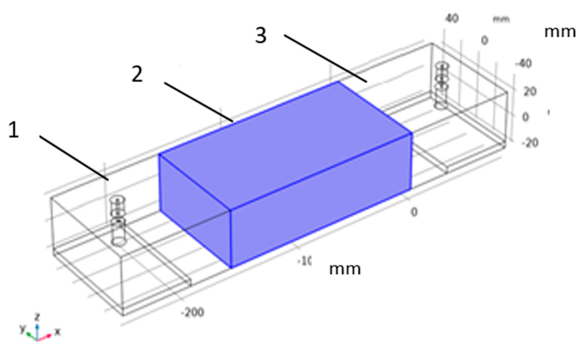
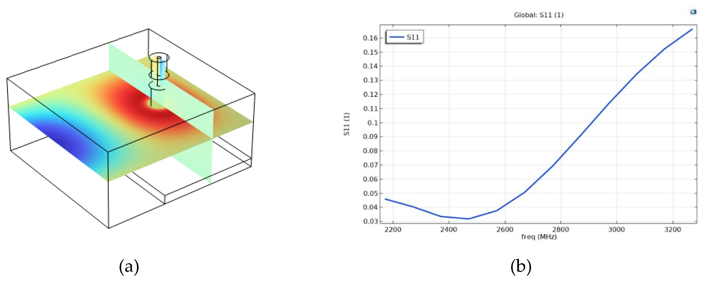
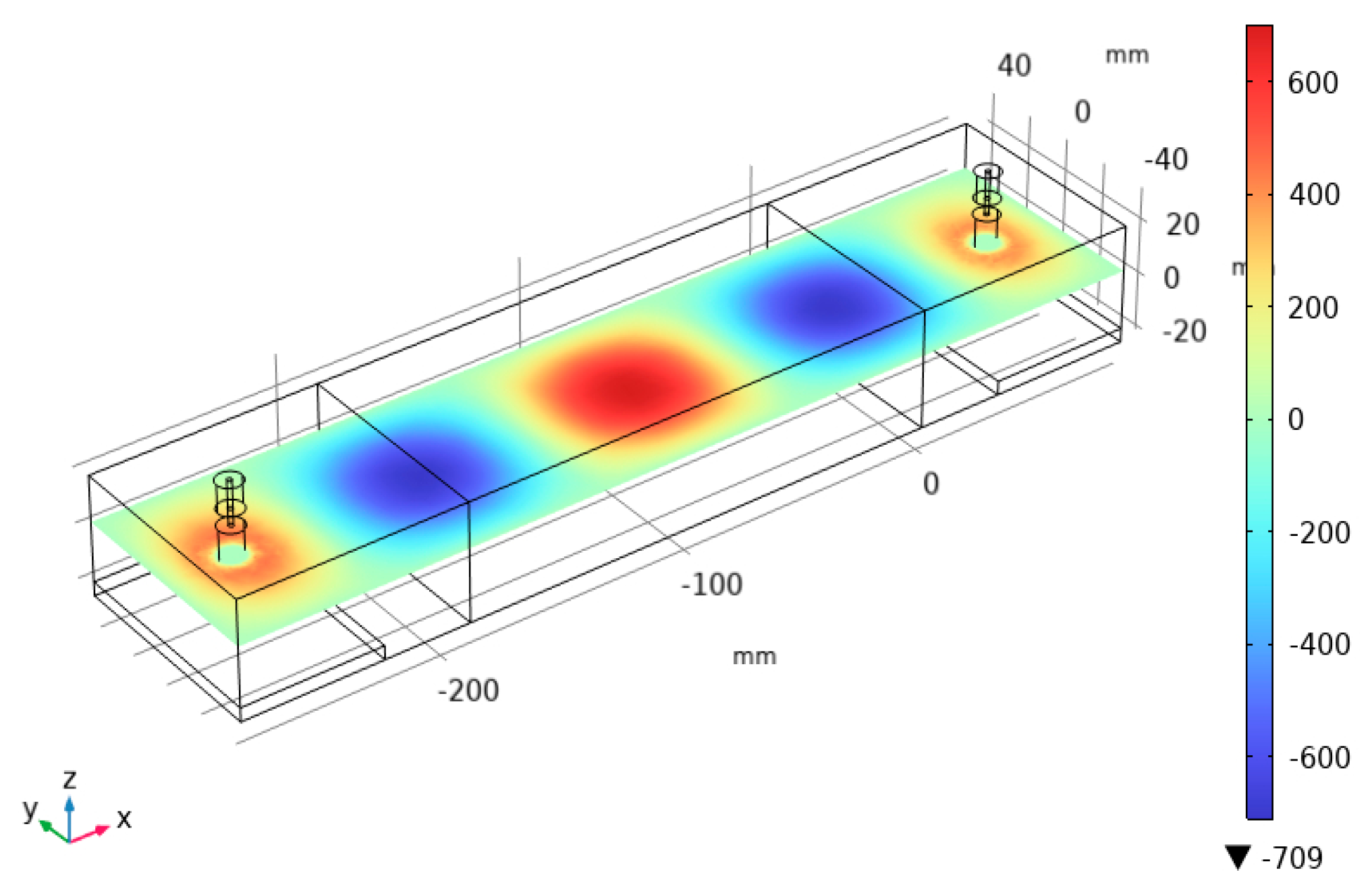
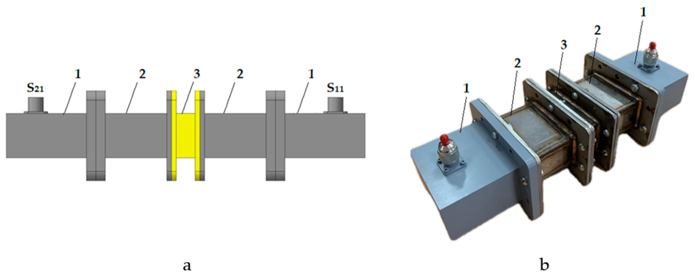
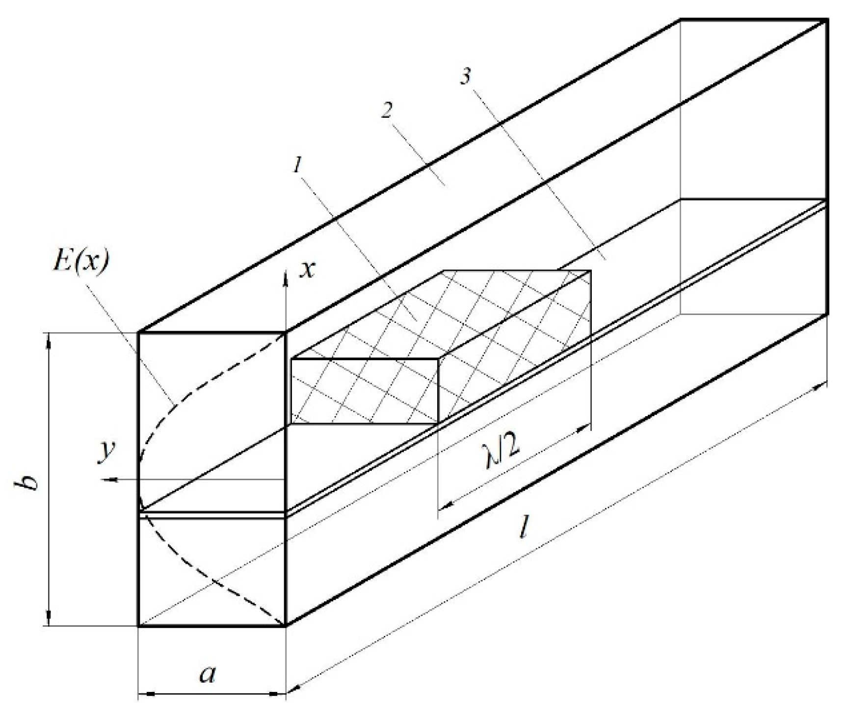
2.2. Selection of Parameters of the Microwave Measuring Line

Waveguide methods which are based on direct measurement of the reflected and transmitted waves in the waveguide section with the object under study, have been widely used to measure dielectric parameters [58,59,60,61].
The microwave measuring line (Figure 1) is a rectangular waveguide, which is connected to coaxial-waveguide transitions on both sides. When a test microwave signal passes through the closed measuring line with the sample, the complex reflection (S11) and transmission (S21) coefficients are measured [62,63,64]. To increase the sensitivity of the measurements, it is necessary to place the sample in the region of the maximum electric field. To do this, it is necessary to determine the length of the microwave measuring line, the thickness of the sample and its location.
To determine the geometry of the measuring microwave line, the distribution of the electromagnetic field strength was studied using mathematical simulation in the Comsol Multiphysics software environment. Since a coaxial-waveguide transition was used to carry out measurements, its mathematical model was built (Figure 2a) and the parameters of S11 were determined in the frequency range of 2.17-3.3 GHz (Figure 2b) to verify the 3D model.
At the next stage of simulation, the length l of the microwave measuring line was determined. For this purpose, the results of the electric field strength distribution in the microwave measuring line at a frequency of 2450 MHz were obtained (Figure 3).
During the mathematical simulation, a series of numerical calculations of the strength E distribution in the microwave measuring line was carried out. As a result, the optimal length l was determined, at which the maximum value of the strength E in the microwave measuring line is equidistant from the input and output ports of the coaxial-waveguide junctions S11 and S21.
According to the waveguide method a sample is placed in a waveguide section and complex scattering parameters of the two ports are measured using a vector network analyzer. This method requires the sample preparation. To reduce error in conducting experimental measurements of S parameters, the thickness of the object must be less than half the wavelength in the specified frequency range.
This thickness can be determined by the formula:
d = c ε 2 f max
where c is the speed of light, fmax is the maximum frequency in the experiment, ε is the expected value of the permittivity.
Based on the results of mathematical simulation, we designed and made a microwave measuring line (Figure 4b) consisting of two arms (2), between which a measuring cell (3) is located, and the entire measuring line is connected to a coaxial-waveguide junction (1). The length of the arms and the measuring cell depends on the thickness of the sample being studied, while the total size of the measuring line should not exceed the calculated value L.
Before starting measuring S parameters, standard calibration of the vector network analyzer (model S5045, Planar LLC, Russia) and accurate measurement of the thickness of the sample under study, located in the measuring cell, were carried out [65,66]. Mathematical processing of the measurement results was carried out by the NRW (Nicolson-Ross-Weir) method for the material of thickness d, installed in the air waveguide line. According to the simulation results, it was found that the convergence of the microwave signals S11 and S21 of the calculated 3D model and the parameters measured using the vector network analyzer showed a convergence of 96%.

2.3. Measurements of Dielectric Properties

A well-known problem in the development of microwave installations is the lack of data on the electrophysical properties of objects due to their great diversity in the structure and composition of matrices, fillers and other additives (plasticizers, fire retardants, etc.). In this regard, the issue of measuring the dielectric properties of HRCs is relevant.
Table 1 shows the results of measurements of permittivity ε , , and the dielectric loss tangent tanδ of composites with an epoxy matrix and various fillers using a vector network analyzer.
The measurements show that the composites with chromite, basalt and magnesite fillers have close values of dielectric loss and permittivity. The composite with silicon carbide filler has a comparatively high value of tanδ = 0.801 and permittivity ε , = 9.0 and effectively interacts with the microwave electromagnetic field. Thus, it is proposed to use silicon carbide SiC which has better absorption properties and withstands higher heating temperatures without its chemical destruction as a filler in the composite.

2.4. Methods

One of the main objectives of the work is to study the process of microwave energy dissipation when exposing on HRCs. For this purpose, numerical simulation of the composite heating process in the microwave electromagnetic field was performed in the COMSOL Multiphysics® software environment. The microwave energy dissipation process was studied at a radiation power of 300 – 1200 W at a frequency of 2450 MHz in the installation with a traveling wave chamber. Microwave chambers of this type have the simplest design and differ from others in better matching with the generator, i.e., they have a higher efficiency. Microwave energy from a power source with a generator is fed to the working chamber via a transmission line, where the composite is heated (Figure 5). On the other hand, the chamber is connected to a matched load to reduce reflection and create a traveling wave effect.
The microwave traveling wave chamber is a section of a waveguide (Figure 6) with geometric dimensions a = 45 mm, b = 90 mm, l = 500 mm, in which the fundamental type of wave TE10 with a wave length λ = 16.7 cm is excited in the waveguide [31]. The location and size of the HRC sample in the microwave chamber are selected so that it is at the maximum strength E of the electric field of the electromagnetic wave. Then, the height of the HRC sample is 40 mm, the width is a, because it is limited by the dimensions of the waveguide, the length is chosen provided λ/2 (where λ is the wavelength).

2.5. Selection of the Shape and Size of the Filler

The structures of a polymer composite with a filler in the form of a single sphere (Figure 7a) and multiple spheres (Figure 7b) have been considered. The shape of the fillers can be different, but is conventionally assumed to be spherical. In this case, a filler of irregular geometry is approximated by spherical particles during simulating. The sizes of the silicon carbide absorber vary from 1 mm to 40 mm. The maximum filler size of 40 mm is limited by the dimensions of the microwave chamber.
The filler size was selected based on the results of numerical simulation of the microwave energy dissipation process of an absorbing sphere of different diameters (Table 2). The mathematical models describing the microwave heating processes of dielectrics were taken as a basis, namely the equations of electrodynamics (Maxwell’s equations) and thermal conductivity (Fourier’s thermal conductivity equation) with the corresponding initial and boundary conditions. Microwave heating was carried out at a power of P=800 W and time τ=60 s.
Thus, microwave heating of the filler in the form of one sphere with a diameter of d = 30 mm and d = 20 mm makes it possible to achieve high temperatures of 629 °C and 542 °C in the volume of the absorber, which are significantly higher than the destruction temperature of the HRC matrix (Figure 8).
It was found that the filler with a diameter of 20 mm provides a high heating rate of 8.3 °C/s at a maximum temperature difference of 30 °C in the sphere volume with a maximum dielectric loss tanδ = 1.1 (Figure 8). These results correspond to the general requirements for HRCs (see the introduction), therefore, further in the work, a composite with a filler of 20 mm in diameter is considered. If the filler diameter is less than 10 mm, the maximum temperature difference in the volume tends to zero (Table 3). Thus, a filler of less than 5 mm in diameter can be used in the composite to obtain a uniform temperature distribution in the HRC volume.

3. Results

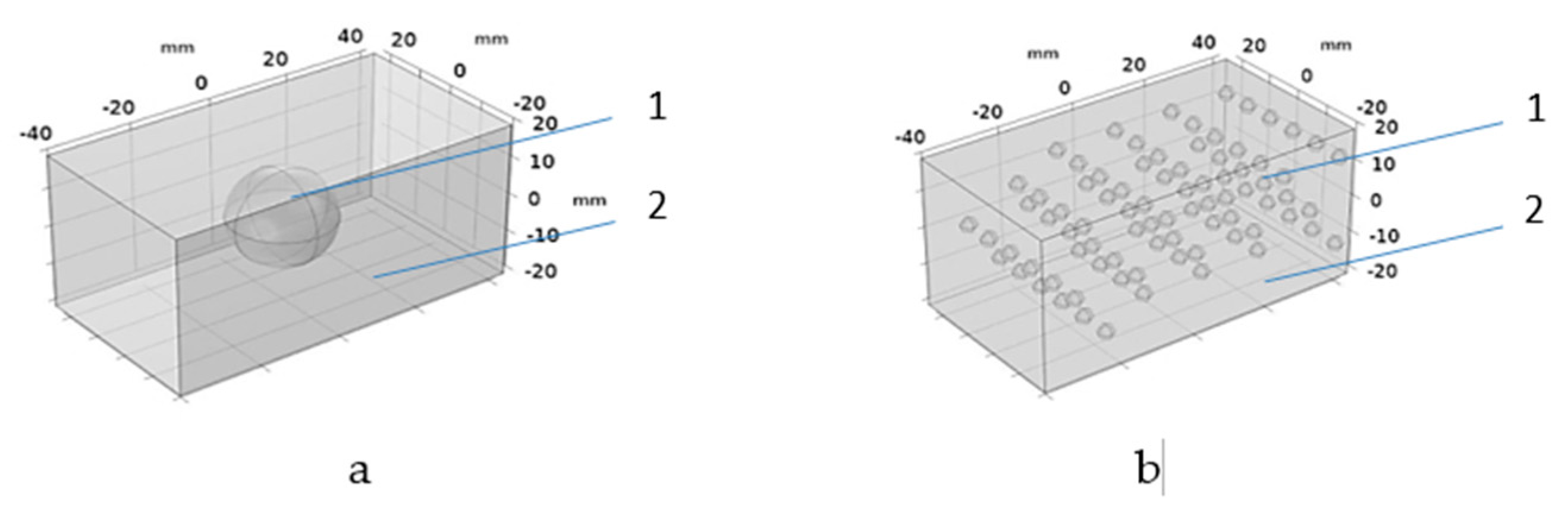
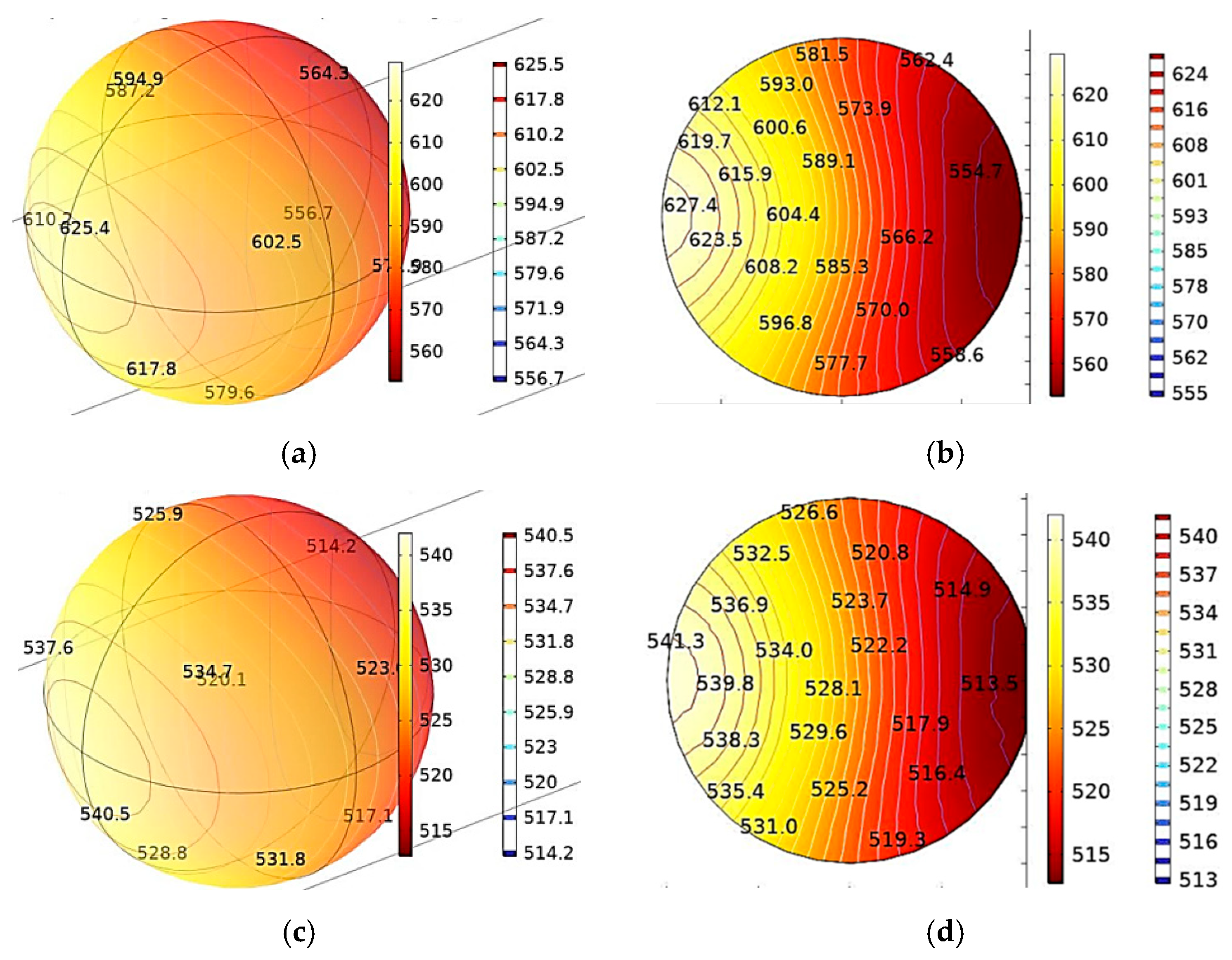
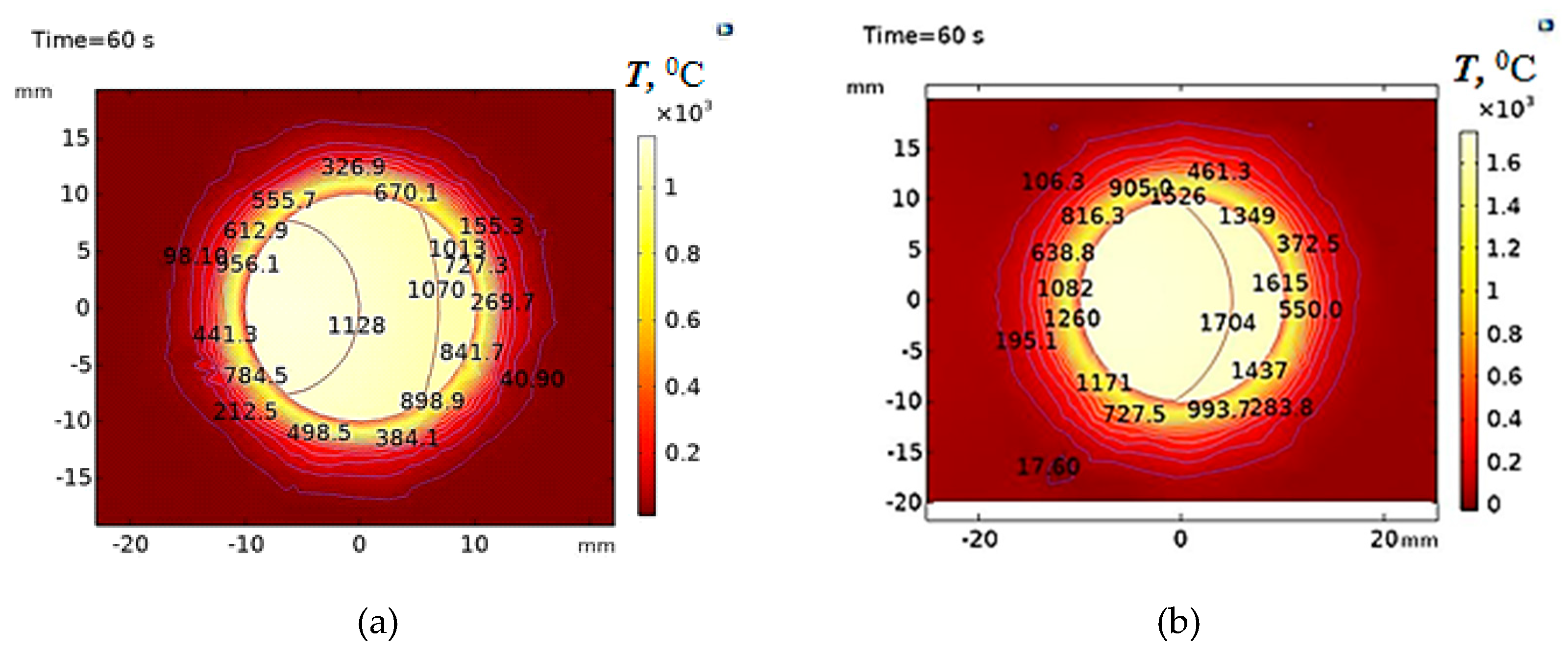
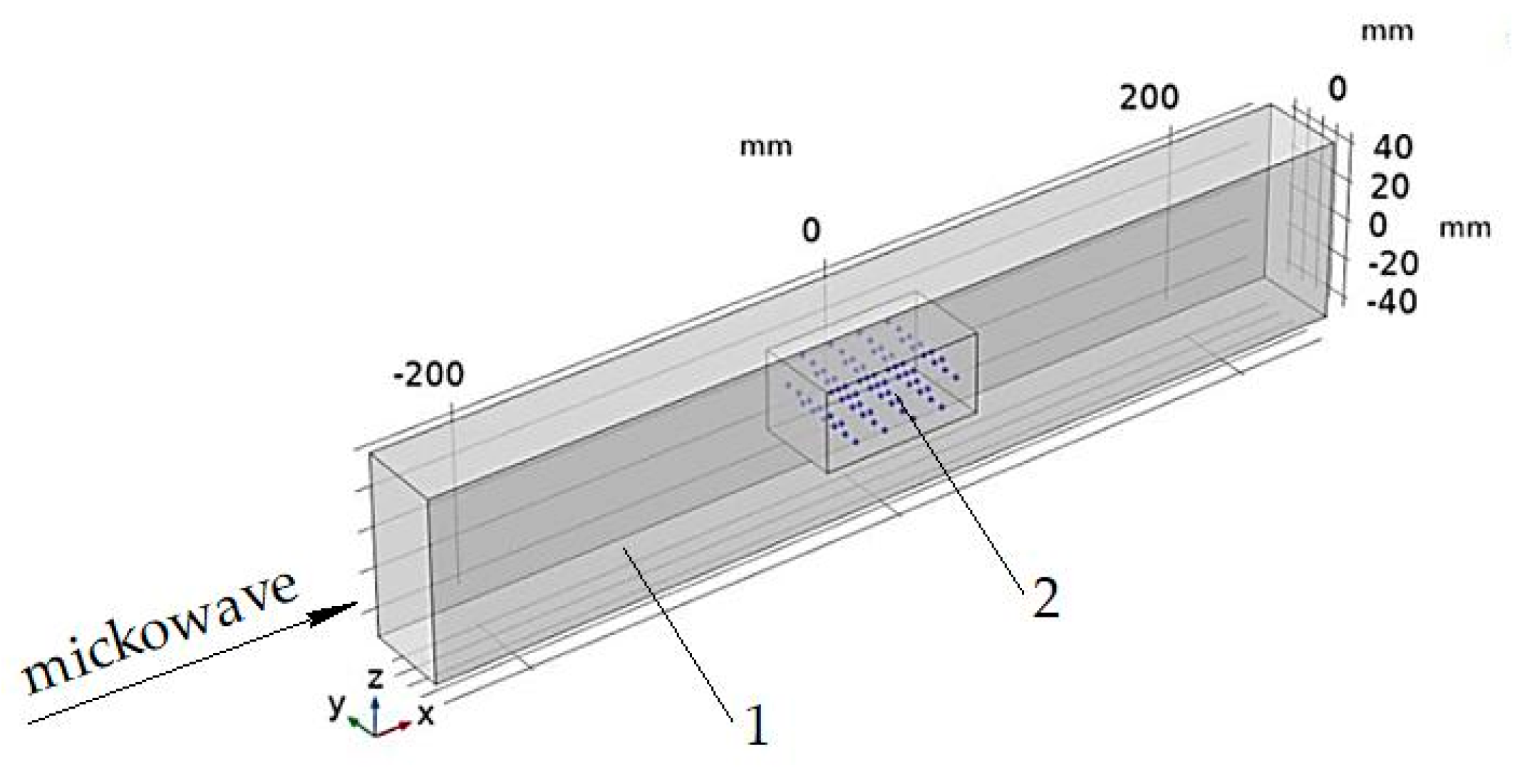
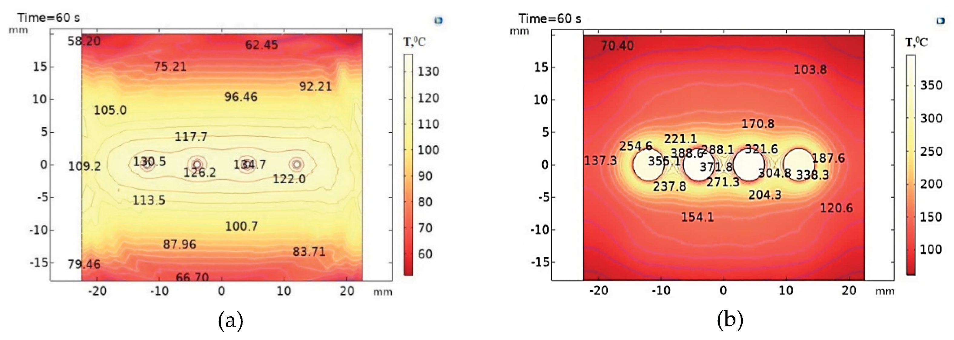
3.1. Study of the Microwave Energy Dissipation Process During Heating of the HRC with a Filler in the Form of a Sphere with a Diameter of d = 20 mm (Figure 7a)

To study the process of the microwave energy dissipation at different power levels, temperature distribution fields in the composite during its heating were obtained. HRCs with a matrix of polytetrafluoroethylene (PTFE) and epoxy resin (ED-20) were considered.
It was found that at microwave radiation power of 900 W or more, heating of the PTFE matrix (tanδ = 0.0003) above 500 °С was observed at a filler heating rate of more than 10 °С/s (Table 3). In this case, matrix damage occurred at a distance of l = 1 mm from the phase boundary between the filler and the matrix, since the temperature was 525 ○С (Table 4). Such conditions meet the requirements for HRCs.
The following results were obtained in studying the microwave energy dissipation process in the HRC with an epoxy resin matrix (ED-20) at different power levels. It was found that the heating of the ED-20 matrix (tanδ = 0.03) above 500 °C and the filler heating rate of more than 10 °C/s were observed at a microwave radiation power of 400 W and more (Table 5). In this case, the matrix destruction occurs at a power of 600 W at a distance of l = 1 mm from the phase boundary between the filler and the matrix, and at a power of 900 W and more at l = 2 mm (Table 6). Accordingly, the matrix temperature at a distance of l = 1 mm and l = 2 mm is above 600 °C. Such conditions meet the requirements for HRCs.
In order to obtain more contrasting temperature distribution fields in the volume of the HRC with matrices of PTFE (Figure 9a) and ED-20 (Figure 9b), a higher microwave power of 1200 W was used. It was found that the HRC with an ED-20 matrix heated up by 589 ○C higher compared to the PTFE matrix. This is explained by the fact that the epoxy resin has higher intrinsic dielectric losses than PTFE. Therefore, as a result of the microwave energy dissipation, the temperature is higher by 507 ○C at the F/M boundary and by 592 ○C in the filler in the HRC with an epoxy matrix compared to the PTFE matrix.
It was found that the damage of the ED-20 matrix as a result of microwave energy dissipation in the HRC was achieved at a lower power of 600 W than for the PTFE matrix. The temperature field dissipation in ED-20 is more than 2 mm from F/M at a high heating rate above 14.3 ○C/s. Thus, HRCs with an ED-20 matrix have higher dissipation rates of the high-energy radio-absorbing composite.

3.2. Study of the Process of Microwave Energy Dissipation During Heating of HRC with a Multiple Sphere Filler (Figure 7b)

Unlike the previous case, the intensity of heating of the HRC with a multiple sphere filler depends not only on the parameters of the microwave exposure, but also on the diameter of the filler and its distribution in the matrix. To study the process of microwave energy dissipation in the HRC with a multiple sphere filler, a geometric model was built (Figure 10), where the absorbing filler is uniformly distributed throughout the volume of the matrix made of ED-20 epoxy resin. In this case, the efficiency of the microwave energy dissipation process is determined not only by the maximum temperature in the volume of the composite, but also by the uniformity of the temperature field in the HRC, which depends on the thermophysical properties of the matrix material.
The results of the temperature field distribution in the HRC with a multiple sphere filler of different diameters were obtained. Table 7 presents the results for the maximum microwave power of 1200 W. It was found that the HRC sample with a multiple sphere filler with a diameter from 1 mm to 5 mm was heated in the microwave field less intensively than the HRC with a filler with one sphere. Thus, for spheres d = 5 mm, the average temperature in the matrix volume is 185 °С. Even at a microwave power of 1200 W, the temperature in the matrix does not reach 500 °С. Therefore, the use of a multiple sphere filler for HRCs is not advisable, since the matrix is not heated up to 500 °С and higher, therefore, destruction and intense damage of the matrix do not occur. This is explained by the equalization of the temperature field in the HRC volume due to more intensive heat exchange between the matrix and the multiple spheres of the filler (Figure 11).

4. Discussion and Novelty of the Approach in Thermal Engineering of Polymers

In this scientific study, within the framework of polymer engineering, the design of a new class of high-energy radio-absorbing composites (HRC) providing high intensity of microwave energy dissipation during heating is scientifically substantiated for the first time.
High-energy radio-absorbing composites (HRC) can be classified by some features as high-energy composites (HEC), in which energy is released as a result of chemical transformations. In turn, high-energy radio-absorbing composites (HEC) differ from HEC by a low level of thermal energy of microwave radiation absorption or its dissipation.
The article proposes a new approach to the classification of HRC, which combines two separate classifications (HEM and HEC), opening up broad opportunities for research in the field of interaction of microwave electromagnetic radiation with composites of various structures to implement their specified functional properties.
It has been established that high-energy radio-absorbing composites (HEC) are a new type of functional materials possessing the properties of a radio-absorbing and high-energy material, characterized by a high heating rate to temperatures from 500 to 2000 °C and higher, which provides such composites with specific areas of application as an initiating or primary substance for fuel ignition, for initiating the explosive transformation of other substances (for example, rocks), for solving special problems in dual-use devices (conversion of thermal energy into mechanical energy), in the processes of sintering or decomposition of materials capable of effectively absorbing microwave energy, etc.
General requirements for a new class of materials (HEC) have been formulated:
-
matrix structure of a composite with a radio-absorbing filler;
-
the radio-absorbing filler must have high dielectric properties, ensuring its heating temperature during microwave energy dissipation of at least 500 °C, which is associated with the destruction temperature and mechanical destruction of the polymer matrix material;
-
the radio-absorbing filler must ensure a high heating rate of at least 10 °C /s during microwave energy dissipation;
-
the choice of matrix material (binder) depends on the functional purpose of the VRC, for example, for initiating transformations (during ignition of rocket fuel), for high-temperature destruction of the polymer with the release of initiating substances, for destruction during the conversion of thermal energy into mechanical energy.
In this paper, for the first time in the framework of thermal engineering of polymers, the design of a new class of high-energy radio-absorbing composites is substantiated, providing a high intensity of microwave energy dissipation during heating. A new approach to the classification of VRCs is proposed, combining the features of high-energy materials and radio-absorbing composites. This opens up broad prospects for research in the field of interaction of microwave radiation with polymer matrices of various nature. A direct relationship is established between the dielectric properties of the matrix and the mechanisms of thermal destruction. The relationship is that thermal breakdown is a consequence of a decrease in the active resistance of the dielectric under the influence of heating in an electric field. This leads to an increase in the active current and a further increase in the heating of the dielectric up to its thermal destruction.
During the curing of thermosetting matrices, shrinkage occurs due to different coefficients of thermal expansion of the matrix and filler, which leads to the occurrence of residual internal stresses and the formation of voids in the area of the “matrix-filler” contact. Under the influence of a microwave electromagnetic field, the number of areas of contact interaction “matrix-filler” increases, due to which the connectivity of dispersed structures increases and the redistribution of the load in the material improves. When a microwave electromagnetic field acts on thermoplastic matrices, the thermoplastic polymer melts due to dielectric heating and the skin effect in areas adjacent to the carbon fibers. The thermoplastic, which has temporarily passed into a viscous-flowing state due to microcapillary effects enhanced by the wave component of the electromagnetic field, affects the filler, forming numerous microformations in it after hardening. At the same time, also due to the increase in the fluidity of the thermoplastic binder, there is a partial or complete filling of the voids in the monolayer remaining after the binder has hardened.

5. Conclusions

As a result of the simulation of the microwave heating process of the HRC with a silicon carbide filler in the form of one sphere and multiple spheres and matrices made of epoxy resin and fluoroplastic, temperature distribution fields were obtained under conditions of different heat transfer. This made it possible to optimize the HRC structure, which ensures the implementation of specified functional properties during the dissipation of microwave energy.
It has been established that the optimal structure of HRC is a composite with a radio-absorbing filler made of silicon carbide in the form of one sphere d = 20 mm based on an ED-20 matrix. This structure of the HRC provides such a temperature distribution between the matrix and the filler during the dissipation of microwave energy, which allows to implement the specified functional properties of the composite. In this case, destruction and mechanical damage of the matrix occur at a low level of microwave power of 400 W and a filler heating rate of more than 10 °С/s.

Author Contributions

Conceptualization, S.K. and A.S.; methodology, A.S. and A.B.; software, Y.K..; validation, Y.K. and A.I.P; formal analysis, N.Zh.; investigation, M.A., E.V. and N.Zh.; resources, S.K..; data curation, S.K.; writing—original draft preparation, A.S.; writing—review and editing, A.I.P. and A.B.; visualization, S.K. and E.V.; supervision, A.S.; project administration, M.A.; funding acquisition, A.B.

Funding

This research was funded by the Russian Science Foundation grant No. 24-29-00796, https://rscf.ru/project/24-29-00796/ and by Science Committee of the Ministry of Science and Higher Education of the Republic of Kazakhstan (grant no. BR24992882).

Institutional Review Board Statement

Not applicable.

Data Availability Statement

The data presented in this study are available in this article.

Conflicts of Interest

The authors declare no conflict of interest.

References

  1. Bardadym, Y.; Vilensky, V. The Influence of Physical Fields on the Thermal or Dielectric Properties of Epoxy Composites. Phys. Chem. Solid State. 2016, 4, 533–538. [Google Scholar] [CrossRef]
  2. Zhang, Q.; He, X. Complex Effects of the External Electric Fields on the Phase Separation of Polymer Blends. Macromolecules. 2024, 57, 597–605. [Google Scholar] [CrossRef]
  3. Sukharev, Y.I.; Matveychuk, Y.V.; Yudina, E.P.; Krupnova, T.G. Change In The Adsorption Activity Of Silicagel Under The Influence Of Magnetic Field. Phys. Chem.: Indian J. 2007, 2, 100–105. [Google Scholar]
  4. Zhang, Q.; He, X. Phase Separation of Polymer Blends Induced by an External Static Electric Field. Chin. J. Polym. Sci. 2022, 41, 972–980. [Google Scholar] [CrossRef]
  5. Tong, S.Y. , Wu, J.M., Huang, Y.T., Tung, M.J., Ko, W.S., Wang, L.C., & Yang, M.D. (2011). Design and characteristics of flexible radio-wave absorber consisted of functional NiCuZn ferrite–polymer composites. Journal of Alloys and Compounds 2011, 509, 2263–2268. [Google Scholar]
  6. Kostishin, V.G.; Isaev, I.M.; Salogub, D.V. Radio-Absorbing Magnetic Polymer Composites Based on Spinel Ferrites: A Review. Polymers 2024, 16, 1003. [Google Scholar] [CrossRef]
  7. Bril’, I.; Voronin, A.; Fadeev, Y.; Pavlikov, A.; Govorun, I.; Podshivalov, I.; Parshin, B.; Makeev, M.; Mikhalev, P.; Afanasova, K.; et al. Laser-Induced Silver Nanowires/Polymer Composites for Flexible Electronics and Electromagnetic Compatibility Application. Polymers 2024, 16, 3174. [Google Scholar] [CrossRef]
  8. Yilmaz Atay, G. , & Bilgiç, N. Radar absorbing properties of different size carbon nanotube reinforced polymer composites. Frontiers in Materials 2024, 11, 1380472. [Google Scholar]
  9. Crank, B.; Fricker, B.; Hubbard, A.; Hitawala, H.; Muna, F.I.; Okunlola, O.S.; Doherty, A.; Hulteen, A.; Powers, L.; Purtell, G.; et al. Electromagnetic Radiation Shielding Using Carbon Nanotube and Nanoparticle Composites. Appl. Sci. 2025, 15, 8696. [Google Scholar] [CrossRef]
  10. Seetha Rama Raju, V. , Kandukuri, S., Singh, A.K., & Satya Narayana Murthy, V. (2024). Magnetic-polymer flexible composites for electromagnetic interference shielding applications. Journal of Materials Science: Materials in Electronics 2024, 35, 2067. [Google Scholar]
  11. Swetha, P. , Aswini, R., Binesh, M., & Muhammed Shahin, T.H. Cost efficient fabrication of flexible polymer metacomposites: Impact of carbon in achieving tunable negative permittivity at low radio frequency range. Materials Today Communications 2023, 34, 105287. [Google Scholar]
  12. Yermakhanova, A.M. , Kenzhegulov, A.K., Meiirbekov, M.N., Samsonenko, A.I., Baiserikov, B.M. Study of Radio Transparency and Dielectric Permittivity of Glass- and Aramid Epoxy Composites. Eurasian Physical Technical Journal 2023, 20, 70–78. [Google Scholar] [CrossRef]
  13. Anaele Opara, F.; Chinedu Obasi, H.; Chukwudi Eke, B.; Uzochukwu Eze, W. Progress in polymer-based composites as efficient materials for electromagnetic interference shielding applications: A review. Current Materials Science 2023, 16, 235–261. [Google Scholar] [CrossRef]
  14. Savchyn, V.P.; Popov, A.I.; Aksimentyeva, O.I.; Klym, H.; Horbenko, Y.Y.; Serga, V.; Moskina, A.; Karbovnyk, I. Cathodoluminescence characterization of polystyrene-BaZrO3 hybrid composites. Low Temp. Phys. 2016, 42, 597–600. [Google Scholar] [CrossRef]
  15. Zhang, J.; Fan, Z.; Li, B.; Ren, D.; Xu, M. Study on Structure–Function Integrated Polymer-Based Microwave-Absorption Composites. Polymers 2024, 16, 2472. [Google Scholar] [CrossRef]
  16. Zena, Y.G. , Woldemariam, M.H., & Koricho, E.G. Nano-additives and their effects on the microwave absorptions and mechanical properties of the composite materials. Manufacturing Review 2023, 10, 8. [Google Scholar]
  17. Kallumottakkal, M. , Hussein, M.I., & Iqbal, M.Z. Recent progress of 2D nanomaterials for application on microwave absorption: a comprehensive study. Frontiers in Materials 2021, 8, 633079. [Google Scholar]
  18. Shchegolkov, A.V.; Shchegolkov, A.V.; Kaminskii, V.V.; Iturralde, P.; Chumak, M.A. Advances in Electrically and Thermally Conductive Functional Nanocomposites Based on Carbon Nanotubes. Polymers 2025, 17, 71. [Google Scholar] [CrossRef] [PubMed]
  19. Aladailah, M.; Tashlykov, O.; Volozheninov, T.; Kaskov, D.; Iuzbashieva, K.; Al-Abed, R.; Acikgoz, A.; Yorulmaz, N.; Yaşar, M.M.; Al-Tamimi, W.; et al. Exploration of physical and optical properties of ZnO nanopowders filled with polydimethylsiloxane (PDMS) for radiation shielding applications. Simulation and theoretical study. Opt. Mater. 2022, 134, 113197. [Google Scholar] [CrossRef]
  20. Zhang, H.; Lin, S. Research Progress with Membrane Shielding Materials for Electromagnetic/Radiation Contamination. Membranes 2023, 13, 315. [Google Scholar] [CrossRef]
  21. Al-Saleh, W.M.; Almutairi, H.M.; Sayyed, M.I.; Elsafi, M. Multilayer radiation shielding system with advanced composites containing heavy metal oxide nanoparticles: A free-lead solution. Sci. Rep. 2023, 13, 18429. [Google Scholar] [CrossRef]
  22. Istlyaup, A. , Myasnikova, L., Bezrukovs, V., Žalga, A., & Popov, A.I. Computer simulation of the electrical properties of carbon nanotubes encapsulated with alkali metal iodide crystals. Low Temperature Physics 2024, 50, 898–904. [Google Scholar]
  23. Kozlovskiy, A.L.; Shlimas, D.I.; Zdorovets, M.V.; Elsts, E.; Konuhova, M.; Popov, A.I. Investigation of the Effect of PbO Doping on Telluride Glass Ceramics as a Potential Material for Gamma Radiation Shielding. Materials 2023, 16, 2366. [Google Scholar] [CrossRef] [PubMed]
  24. Li, J.S.; Huang, H.; Zhou, Y.J.; Zhang, C.Y.; Li, Z.T. Research progress of graphene-based microwave absorbing materials in the last decade. Journal of Materials Research 2017, 32, 1213–1230. [Google Scholar] [CrossRef]
  25. Fionov, A.; Kraev, I.; Yurkov, G.; Solodilov, V.; Zhukov, A.; Surgay, A.; Kuznetsova, I. and Kolesov, V. Radio-Absorbing Materials Based on Polymer Composites and Their Application to Solving the Problems of Electromagnetic Compatibility. Polymers 2022, 14, 3026. [Google Scholar] [CrossRef]
  26. Ahmad, A.F.; Ab Aziz, S.; Abbas, Z.; Obaiys, S.J.; Khamis, A.M.; Hussain, I.R.; Zaid, M.H.M. Preparation of a Chemically Reduced Graphene Oxide Reinforced Epoxy Resin Polymer as a Composite for Electromagnetic Interference Shielding and Microwave-Absorbing Applications. Polymers 2018, 10, 1180. [Google Scholar] [CrossRef]
  27. Aneli, J.; Natriashvili, T.; Shamanauri, L. Radio wave absorbing polymer composites with electric conducting and magnetic particles. Bull. Georgian Natl. Acad. Sci. 2019, 13, 47–52. [Google Scholar]
  28. Gu, W.; Zhan, R.; Li, R.; Liu, J.; Jiaqiao, Z. Preparation and Characterization of PU/PET Matrix Gradient Composites with Microwave-Absorbing Function. Coatings. 2021, 11, 982. [Google Scholar] [CrossRef]
  29. Barudov, E.; Ivanova, M. Study of the parameters of conductive textile fabrics for protection against high-frequency electromagnetic radiation. 13th Electrical Engineering Faculty Conference (BulEF). 2021, 1–5. [Google Scholar] [CrossRef]
  30. Lakoza, A.M. Review of modification methods of magnetic, shielding, radio-absorbing materials and coatings. Control, communication and security systems. 2023, 4, 196–218. [Google Scholar] [CrossRef]
  31. Costa, F.; Monorchio, A.; Manara, G. Theory, design and perspectives of electromagnetic wave absorbers. IEEE Electromagn. Compat. Mag. 2016, 2, 67–74. [Google Scholar] [CrossRef]
  32. Luo, F.; Liu, D.; Cao, T.; Cheng, H. Study on broadband microwave absorbing performance of gradient porous structure. Adv. Compos. Hybrid Mater. 2021, 3, 591–601. [Google Scholar] [CrossRef]
  33. Delfini, A.; Marta, A.; Vricella, A.; Santoni, F. Advanced radar absorbing ceramic-based materials for multifunctional applications in space environment. Materials 2018, 9, 1730. [Google Scholar] [CrossRef]
  34. Yao, Y.; Jin, S.; Zou, H.; Li, J. Polymer-based lightweight materials for electromagnetic interference shielding: A review. J. Mater. Sci. 2021, 56, 6549–6580. [Google Scholar] [CrossRef]
  35. Zhao, Y.; Li, C.; Lang, T.; Gao, J.; Zhang, H.; Zhao, Y.; Guo, Z.; Miao, Z. Research Progress on Intrinsically Conductive Polymers and Conductive Polymer-Based Composites for Electromagnetic Shielding. Molecules 2023, 28, 7647. [Google Scholar] [CrossRef]
  36. Jiang, D.; Murugadoss, V.; Wang, Y.; Lin, J. Electromagnetic interference shielding polymers and nanocomposites-a review. Polym. Rev. 2019, 2, 280–337. [Google Scholar] [CrossRef]
  37. Kumar, R.; Sahoo, S.; Joanni, E.; Singh, R. Recent progress on carbon-based composite materials for microwave electromagnetic interference shielding. Carbon. 2021, 177, 304–331. [Google Scholar] [CrossRef]
  38. Abubakarov, A.G.; Reyzenkind, Y.A. Current state and future development of research procedure of the radar-absorbing materials based on heterogeneous structures. RSEMW 2017, 161-164. [Google Scholar] [CrossRef]
  39. Gulmagomedov, N.H.; Lukashenko, Yu.I. Effect of heating on radio engineering properties of flexible radio absorbing material. Bulletin of Moscow Power Engineering Institute. MPEI Bulletin. 2017, 4, 142–145. [Google Scholar] [CrossRef]
  40. Sivak, A.S.; Sahaji, G.V.; Kalganova, S.G.; Kadykova, Y.A.; Trigorly, S.V. The Effect of a Microwave Electromagnetic Field on the Temperature Distribution in Composite Materials. Electricity 2023, 11, 27–33. [Google Scholar] [CrossRef]
  41. Sivak, A.S.; Kalganova, S.G.; Kadykova, Y.A.; Trigorlyy, S.V.; Vasinkina, E.Y.; Sivak, T.P. Modeling the Heating of Composites with Absorbing Fillers of Various Shapes in a Microwave Chamber with a C-Slit Emitter. Electricity 2024, 10, 46–56. [Google Scholar] [CrossRef]
  42. Bekeshev, A.; Mostovoy, A.; Shcherbakov, A.; Zhumabekova, A.; Serikbayeva, G.; Vikulova, M.; Svitkina, V. Effect of Phosphorus and Chlorine Containing Plasticizers on the Physicochemical and Mechanical Properties of Epoxy Composites. J. Compos. Sci. 2023, 7, 178. [Google Scholar] [CrossRef]
  43. Ahmadi, Z. Epoxy in nanotechnology: A short review. Prog. Org. Coat. 2019, 132, 445–448. [Google Scholar] [CrossRef]
  44. Capricho, J.C.; Fox, B.; Hameed, N. Multifunctionality in epoxy resins. Polym. Rev. 2020, 60, 1–41. [Google Scholar] [CrossRef]
  45. Hsissou, R.; Bekhta, A.; Khudhair, M.; Berradi, M.; El-Aouni, N.; Elharfi, A. Review on epoxy polymers composites with improved properties. J. Chem. Technol. Metall. 2019, 54, 1128–1136. [Google Scholar] [CrossRef]
  46. Dhanumalayan, E.; Joshi, G.M. Performance properties and applications of polytetrafluoroethylene (PTFE)—a review. Adv. Compos. Hybrid Mater. 2018, 1, 247–268. [Google Scholar] [CrossRef]
  47. Shindalkar, S.S.; Humbe, S.S.; Joshi, G.M.; Kumar, C.R. Engineering properties of Teflon derived blends and composites: a review. Polym.-Plast. Technol. Mater. 2022, 61, 1973–1987. [Google Scholar] [CrossRef]
  48. Elmahaishi, M.; Raba’ah, A.; Ismayadi, I.; Farah, M. A review on electromagnetic microwave absorption properties: their materials and performance. J. Mater. Res. Technol. 2022, 20, 2188–2220. [Google Scholar] [CrossRef]
  49. Sushmita, K.; Madras, G.; Bose, S. The journey of polycarbonate-based composites towards suppressing electromagnetic radiation. Funct. Compos. Mater. 2021, 2, 13. [Google Scholar] [CrossRef]
  50. Gubernat, A.; Stobierski, L.; Grabowski, G. Microstructure and mechanical properties of SiC materials. Ceramika. Ceramics 2006, 96, 205–215. [Google Scholar]
  51. Bekeshev, A.; Vasinkina, E.; Kalganova, S.; Trigorly, S.; Kadykova, Y.; Mostovoy, A.; Shcherbakov, A.; Lopukhova, M.; Zhanturina, N. Modeling of the Modification Process of an Epoxy Basalt-Filled Oligomer in Traveling Wave Microwave Chambers. J. Compos. Sci. 2023, 7, 392. [Google Scholar] [CrossRef]
  52. Bekeshev, A.; Vasinkina, E.; Kalganova, S.; Kadykova, Yu.; Mostovoy, A.; Shcherbakov, A.; Lopukhova, M.; Aimaganbetova, Z. Microwave modification of an epoxy basalt-filled oligomer to improve the functional properties of a composite based on it. Polymers 2023, 15, 2024. [Google Scholar] [CrossRef] [PubMed]
  53. Duong, P. Evaluating the Chemical Composition and Quality of Magnesite Ore in the Sró Area, Gia Lai Province, Vietnam. Iraqi Geol. J. 2024, 57, 79–86. [Google Scholar] [CrossRef]
  54. Mostovoy, A.S.; Nurtazina, A.S.; Burmistrov, I.N.; Kadykova, Y.A. Effect of finely dispersed chromite on the physicochemical and mechanical properties of modified epoxy composites. Russ. J. Appl. Chem. 2018, 91, 1758–1766. [Google Scholar] [CrossRef]
  55. Vaggar, G.B.; Kamate, S.; Badyankal, P.V. A study on thermal conductivity enhancement of silicon carbide filler glass fiber epoxy resin hybrid composites. Mater. Today: Proc. 2022; 66. [Google Scholar] [CrossRef]
  56. Suresh, A.; Bhargavi, P.; Kiran Kumar, M. Simulation and mechanical characterization on kevlar epoxy reinforced composite with silicon carbide filler. Mater. Today: Proc. 2020; 38. [Google Scholar] [CrossRef]
  57. Matykiewicz, D.; Barczewski, M.; Michałowski, S. Basalt powder as an eco-friendly filler for epoxy composites: Thermal and thermo-mechanical properties assessment. Compos. B: Eng. 2018, 164, 272–279. [Google Scholar] [CrossRef]
  58. Benali, L.A.; Tribak, A.; Terhzaz, J.; Mediavilla, A. An Accurate Method to Estimate Complex Permittivity of Dielectric Materials at X-band Frequencies. Int. J. Microw. Opt. Technol. 2020, 15, 10–16. [Google Scholar]
  59. Terhzaz, J.; Ammor, H.; Assir, A.; Mamouni, A. Application of the FDTD method to determine complex permittivity of dielectric materials at microwave frequencies using a rectangular waveguide. Microw. Opt. Technol. Lett. 2007, 49, 1964–1968. [Google Scholar] [CrossRef]
  60. Vyas, A.; Rana, V.; Gadani, D.; Prajapati, A. Cavity perturbation technique for complex permittivity measurement of dielectric materials at X-band microwave frequency. Int. Conf. Recent Adv. Microw. Theory Appl. 2008, 836–838. [Google Scholar] [CrossRef]
  61. Kumar, A.; Singh, G. Measurement of dielectric constant and loss factor of the dielectric material at microwave frequencies. Prog. Electromagn. Res. 2007; 69, 47–54. [Google Scholar] [CrossRef]
  62. Mandrić, V.R.; Rupčić, S.; Srnović, M.; Benšić, G. Measuring the dielectric constant of paper using a parallel plate capacitor. Int. J. Electr. Comput. Eng. Syst. 2018, 9, 1–10. [Google Scholar] [CrossRef]
  63. Pauli, M.; Kayser, T.; Wiesbeck, W. A versatile measurement system for the determination of dielectric parameters of various materials. Meas. Sci. Technol. 2007, 18, 1046–1053. [Google Scholar] [CrossRef]
  64. Sheen, J.; Mao, W.; Weihsing, L. Study on the Measurements Techniques of Microwave Dielectric Properties. Natl. Telecommun. Symp. 2007, 349–352. [Google Scholar]
  65. Chang, T.; Zhang, X.; Yang, C.; Sun, Z.; Cui, H.-L. Measurement of complex terahertz dielectric properties of polymers using an improved free-space technique. Meas. Sci. Technol. 2017, 28, 045002. [Google Scholar] [CrossRef]
  66. Chang, T.; Zhang, X.; Zhang, X.; Cui, H.-L. Accurate determination of dielectric permittivity of polymers from 75  GHz to 16  THz using both S-parameters and transmission spectroscopy. Appl. Opt. 2017, 56, 3287. [Google Scholar] [CrossRef] [PubMed]
Figure 1. Geometric model of the microwave measuring line: 1 - coaxial-waveguide transition (S21); 2 - measuring line; 3 - coaxial-waveguide transition (S11).
Preprints 177639 g001
Figure 2. Results of numerical simulation: a distribution of electric field strength in the coaxial-waveguide junction; b graph of the dependence of S11 (dB) on frequency (MHz).
Preprints 177639 g002
Figure 3. Distribution of electric field strength in the microwave measuring line.
Preprints 177639 g003
Figure 4. Microwave measuring line: a – 3D model, b – photo.
Preprints 177639 g004
Figure 5. Structural diagram of the microwave installation.
Preprints 177639 g005
Figure 6. Scheme of the arrangement of the HRC sample (1) in the microwave traveling wave chamber (2) on the substrate (3), where E(x) is the electric field strength diagram.
Preprints 177639 g006
Figure 7. Diagram of the filler arrangement in the HRC matrix in the form of one sphere (a) and multiple spheres (b), where 1 is the filler, 2 is the matrix (binder).
Preprints 177639 g007
Figure 8. Temperature distribution fields of the filler with a diameter of d = 30 mm (a,b) and d = 20 mm (c,d) during microwave heating: (a,c) - in volume, (b,d) - in section.
Preprints 177639 g008
Figure 9. Temperature distribution fields at a microwave power of 1200 W in the cross-section of the HRC with a matrix: a – made of polytetrafluoroethylene (PTFE); b – made of ED-20 epoxy resin.
Preprints 177639 g009
Figure 10. Geometric model of a microwave chamber (1) with a HRC sample (2) with a multiple sphere filler.
Preprints 177639 g010
Figure 11. Temperature distribution in the volume of HRC with fillers d = 5 mm at a microwave power of 1200 W in sections: a – xz; b – yz.
Preprints 177639 g011
Table 1. Dielectric parameters of composites with an epoxy resin matrix with various absorbent fillers.
Composition of the cured composite (matrix + filler) Dielectric loss tangent, tanδ Permittivity, ε ,
ED 20 0.029 3.5
ED 20 + silicon carbide 0.801 9.0
ED 20 + chromite 0.095 5.4
ED 20 + basalt 0.086 3.7
ED 20 + magnesite 0.115 6.1
Table 2. Dependence of temperature throughout the volume of the filler sphere on its diameter.
Diameter of the filler sphere d, mm Maximum temperature, °С Average temperature, °С Temperature gradient in the filler sphere, °С Heating rate, °С/s
40 445 384 106 7.0
30 629 587 76 10.0
20 542 526 30 8.3
10 329 328 2.7 5.0
5 285 285 0.2 4.3
Table 3. Influence of microwave radiation power on the temperature characteristics of the HRC with a polytetrafluoroethylene matrix (PTFE).
Microwave radiation power,
W
Maximum temperature in the filler, °С Maximum temperature at the boundary F/M ⃰, °С Filler heating rate, °С/s
300 304 302 4.6
600 588 584 9.3
900 872 866 14.1
1200 1156 1149 18.8
* F/M - phase boundary between filler and matrix.
Table 4. Influence of microwave power on temperature distribution in the polytetrafluoroethylene (PTFE) matrix at a distance (l) from the phase boundary between the filler and the matrix.
Microwave radiation power, W Matrix temperature at l = 1 mm from the F/M phase boundary ⃰, °С Matrix temperature at l = 2 mm from the F/M phase boundary ⃰, °С Matrix temperature at l = 4 mm from the F/M phase boundary ⃰, °С
300 184 118 42
600 360 205 86
900 525 300 105
1200 698 389 140
* F/M - phase boundary between filler and matrix.
Table 5. Influence of microwave radiation power on temperature characteristics of the HRK with an epoxy resin matrix (ED-20).
Microwave radiation power, W Maximum temperature in the filler, °С Maximum temperature at the boundary F/M ⃰, °С Filler heating rate, °С/s
300 452 450 7.1
400 648 644 10.8
600 884 879 14.3
900 1316 1309 21,5
1200 1748 1738 28.7
* F/M - phase boundary between filler and matrix.
Table 6. Influence of microwave radiation power on the temperature distribution in the epoxy resin matrix (ED-20) at a distance (l) from the phase boundary between the filler and the matrix.
Microwave radiation power, W Matrix temperature at l = 1 mm from the F/M phase boundary ⃰, °С Matrix temperature at l = 2 mm from the F/M phase boundary ⃰, °С Matrix temperature at l = 4 mm from the F/M phase boundary ⃰, °С
300 300 218 119
400 444 295 144
600 601 403 205
900 897 600 301
1200 1205 786 387
* F/M - phase boundary between filler and matrix.
Table 7. Dependence of the average temperature in HRC on the diameter of the filler spheres at a microwave power of 1200 W.
Filler sphere diameter, mm Average temperature in the spheres of fillers, °С Average temperature in the matrix volume, °С Average temperature difference between filler and matrix, °С
1 148 121 27
2 198 125 73
3 238 136 102
4 372 157 215
5 482 185 297
Disclaimer/Publisher’s Note: The statements, opinions and data contained in all publications are solely those of the individual author(s) and contributor(s) and not of MDPI and/or the editor(s). MDPI and/or the editor(s) disclaim responsibility for any injury to people or property resulting from any ideas, methods, instructions or products referred to in the content.
Copyright: This open access article is published under a Creative Commons CC BY 4.0 license, which permit the free download, distribution, and reuse, provided that the author and preprint are cited in any reuse.
Prerpints.org logo

Preprints.org is a free preprint server supported by MDPI in Basel, Switzerland.

Subscribe

Disclaimer

Terms of Use

Privacy Policy

Privacy Settings

© 2026 MDPI (Basel, Switzerland) unless otherwise stated