Submitted:
03 September 2025
Posted:
04 September 2025
You are already at the latest version
Abstract
As the world is technologically advancing, the integration of FSO communication in non-terrestrial platforms is transforming the landscape of global connectivity. By enabling high-data-rate inter-satellite links, secure UAV-ground channels, and efficient HAPS backhaul, FSO technology is paving the way for sustainable 6G non-terrestrial networks. However, the stringent requirement for precise line-of-sight (LoS) alignment between the optical transmitter and receivers poses a hindrance in practical deployment. As non-terrestrial missions require continuous movement across the mission area, the platform is subject to vibrations, dynamic motion, and environmental disturbances. This makes the LoS between the transceivers difficult. While fine-pointing mechanisms such as fast steering mirrors and adaptive optics are effective for microradian angular corrections, they rely heavily on an initial coarse alignment to maintain the LoS. Coarse pointing modules or gimbals serve as the primary mechanical interface for steering and stabilizing the optical beam over wide angular ranges. This survey presents a comprehensive analysis of coarse pointing and gimbal modules that are being used in FSO communication systems for non-terrestrial platforms. The paper classifies gimbal architectures based on actuation type, degrees of freedom, and stabilization strategies. Key design trade-offs are examined, including angular precision, mechanical inertia, bandwidth, and power consumption, which directly impact system responsiveness and tracking accuracy. This paper also highlights emerging trends such as AI-driven pointing prediction, lightweight gimbal design for SWap-constrained platforms. The final part of the paper discusses about open challenges and research directions in developing scalable and resilient coarse pointing systems for aerial FSO networks.
Keywords:
Optical Wireless Communication
; UAV
; FSO
; non-terrestrial platforms
; Gimbal
; ATP
; Coarse pointing mechanism
; AI/ML predictive pointing
1. Introduction
With 6G aiming to extend seamless connectivity beyond terrestrial limits, non-terrestrial platforms including satellites, HAPS, and UAVs are increasingly relying on free-space optical (FSO) communication to deliver high-capacity, low-latency, and secure links across space–air–ground networks. The rapid increase in the applications of unmanned aerial vehicles (UAVs) across commercial, military, and scientific sectors has created a growing demand for high-throughput, low-latency, and secure communication links. Applications such as real-time video surveillance, environmental monitoring, aerial mapping, and autonomous swarming operations require wireless communication systems capable of supporting multi-gigabit data rates and robust connectivity because of the dynamic and interference-prone mission environments [1,2].
Free-space optical (FSO) communication has emerged as a viable solution to conventional radio frequency (RF) systems’ limited spectrum, low data rates, larger beam divergence, and lack of terminal security. FSO communication systems exploit the vast spectrum available in the optical domain, thereby enabling high data transmission capacity. Owing to their inherently narrow beam divergence, these systems offer high spatial confinement of the signal, which not only enables high-capacity links but also enhances link security against interception and jamming. In terms of size, weight, and power (SWaP), FSO systems are proven to be more compact due to shorter wavelengths in the infrared and visible range. The resulting narrow beam divergence can be described by Equation (1) where is beam divergence, is the wavelength, and D is aperture [3,4,5].
FSO systems benefit from shorter wavelengths in the optical regime, which allow the use of relatively smaller apertures compared to RF systems for achieving the same beam divergence. As a result, the transmit and receive optics are more compact and lightweight than conventional RF systems. This, however, brings the challenge of precise alignment and stabilization mechanisms for FSO systems. Components like collimators, lenses, micro electro-mechanical systems (MEMS) mirrors, solid-state lasers, and fibre-based components contribute to low system mass. The narrow divergence of optical beams leads to highly directional links, which reduces the energy dispersion and enables lower transmit power requirements.
Further, due to the high directivity of optical beams, sidelobe loss is negligible since most of the transmitted power is concentrated within a narrow divergence angle. These conditions have made FSO systems ideal for SWaP-constrained platforms like UAVs, CubeSats, and microsatellites. However, where smaller wavelength and narrow beam divergence are a boon for FSO links, there are also certain reasons for bane in these systems. FSO with non-terrestrial platforms is inherently prone to misalignment, due to the continuous platform motion, atmospheric disturbances, and mechanical disturbances caused by non-terrestrial platform movements and vibrations during aerial missions [6]. Therefore, it is essential to maintain a stable optical link and precise alignment between transceivers during aerial missions. Similarly, in the context of emerging 6G non-terrestrial networks, FSO links face unique challenges. While their high capacity and secure narrow-beam communication make them ideal for inter-satellite, satellite-to-ground, and HAPS/UAV backhaul, these same characteristics also necessitate ultra-precise pointing, acquisition, and tracking (PAT). The dynamic motion of non-terrestrial platforms, coupled with atmospheric turbulence and platform jitter, can easily disrupt alignment. In order to guarantee dependable FSO connectivity in upcoming 6G NTN deployments, strong beam steering, AI-driven predictive tracking, and hybrid RF–optical control mechanisms are essential. Figure 1, provides a visual representation of the core challenges that must be overcome during FSO-based communication with non-terrestrial platforms. This precise alignment in these platforms is achieved through a two-stage process that involves coarse pointing and fine pointing. Coarse pointing mechanisms are used to provide wide-range beam steering to bring the receiver within the acquisition field-of-view (FoV), whereas fine pointing systems make high-resolution angular corrections using MEMS mirrors, or liquid crystal deflectors [7].
In coarse pointing mechanisms, gimbal-based systems are widely used due to their mechanical simplicity, robustness, and ability to support large angular deflection with high repeatability [8]. The Figure 2 gives a basic representation of how gimbal modules are being used for maintaining the line of sight with aerial platforms and keeping the optical communication link intact. As seen in the respective figure, the gimbal has two kinds of movement, i.e., azimuth and elevation, to achieve the target. Where azimuth and elevation correspond to the yaw and pitch movement, respectively. This survey reviews the current state-of-the-art in coarse pointing modules, with a focus on gimbal systems designed for FSO communication in aerial platforms. This paper explores mechanical configurations, actuation techniques, control strategies, and integration methods with onboard sensors and navigation systems of different models that are being used and have been published by researchers. This paper also lists key challenges such as SWaP constraints, stabilisation under flight dynamics, and future directions involving AI-enhanced predictive tracking and multi-agent coordination.
2. Existing Technologies and Implementations
This section reviews state-of-the-art literature, prototypes, and commercial/experimental systems implementing coarse pointing gimbals for FSO communication in non-terrestrial platforms. Here, this comparative analysis highlights performance metrics and trade-offs.
2.1. Literature Survey
Gimbal systems are a critical component in FSO communication systems, and researchers are actively working in this field to build more robust, precise, and accurate pointing systems.
In [9], the researcher investigates the feasibility of using a mechanical gimbal for alignment and tracking in an FSO communication link between a ground station and an aerial platform. Their experimental setup involved a 633 nm helium-neon laser mounted on the gimbal, with its position measured by a high-resolution position-sensing photodiode. The data acquisition and gimbal were controlled via a computer. Their paper focuses more on the gimbal’s mechanical capabilities than on control stack details. For tracking algorithms, the authors analysed their gimbal’s repeatability and error, which allowed them to use that error distribution in the alignment and tracking algorithms. As per their analysis, the gimbal’s repeatability for elevation was 0.41 m () and for azimuth was 1.24 m (), with an overall pointing error of 0.3 m (). The simulation results suggested that the natural beam divergence in FSO links, even due to atmospheric turbulence, can effectively offset the gimbal repeatability and accuracy errors, which can make the gimbal a more efficient tool for ATP in ground-to-UAV FSO links.
In [10], the authors proposed a free-space experimental laser terminal (FELT) for the high altitude platforms (HAPs) where a motorized periscope was used for beam steering. The periscope was able to rotate on two axes, i.e., azimuth and elevation, to direct the optical beam. The periscope had a clear aperture of 50 mm. The periscope was being used to focus the incoming beacon light from the ground station onto a CMOS tracking camera, and then the video signal was processed by a compact vision system, which ran control algorithms to keep the periscope aimed at the ground station’s beacon.
In [11], a research paper details the development of an FSO tracking and auto-alignment transceiver system and demonstrates its ability to maintain LOS with mobile platforms like UAVs. The system utilises a mechanical gimbal with servo motors, a position sensing detector (PSD) to receive the signal, a 40mW industrial laser module for data transmission, and a computer for coordination. In this paper, the system uses a simple proportion algorithm that calculates gimbal coordinates based on the laser spot’s position on the PSD and a pre-determined correction coefficient. This coefficient varies across different zones of PSD to ensure accurate recentering and prevent overshooting. The system’s efficiency was tested on a mobile unit on a model train track, and it maintained alignment even at angular velocities up to . The gimbal specifications indicate a maximum angular speed of 60°/s, and experimental results further demonstrate that the system is capable of maintaining power above the critical thresholds during operation, thereby validating its overall efficiency.
In [12], the authors have developed a high-performance, two-axis gimbal system for free-space laser communications onboard UAVs. Their system aims to achieve affordable, reliable, and secure air-to-air laser communication between two UAVs. This custom-designed gimbal offers a FoV in both azimuth and elevation, with increased velocities of up to per second. It is a 24-volt system with integrated motor controllers and a driver. This system also complements a passive vibration isolation system. The gimbal uses piezoelectric servo motors, a signal amplifier, a motor controller, an onboard flight computer, and a tracking algorithm. Their tracking algorithm has been developed to aim an airborne laser at a stationary ground station with known GPS coordinates, by autonomously calculating a LoS vector in real-time using the UAV’s differential GPS and IMU data along with the ground station’s GPS location.
In [13], the authors have used a MEMS-based modulating retroreflector (MRR) as the communication terminal onboard the UAV. Their design significantly reduces power, size, and weight on the UAV by eliminating the need for a laser transmitter and ATP subsystems on the UAV platform. In contrast, the ground station design utilises ATP as a subsystem, where a two-axis gimbal for coarse pointing and an FSM is employed. This gimbal features a high-speed control system with a speed of up to and a resolution of , while the FSM has a maximum angular resolution of . They are using a beacon-based tracking algorithm, where the laser beacon is employed at the ground station. The gimbal continuously tracks the UAV’s trajectory using GPS data. The beacon’s reflection from the MRR is monitored by an IR camera to determine the UAV’s exact position. Fine positioning is achieved by correlating the beacon image’s position on the camera’s focal plane with the necessary FSM movement to illuminate MRR. The system also manages laser power optimally through distance-dependent beam-divergence control.
In [14], the author presents a design and prototype of a compact, lightweight two-axis gimbal for air-to-air and air-to-ground laser communication with UAVs. The gimbal incorporates a refractive telescope with diameter aperture folded between mirrors, and an FSM for fine pointing. The gimbal uses custom-built servo motors with optical encoders, where the azimuth stage connects via a slip ring, and the elevation stage is equipped with passive optics, supported with custom-built ceramic-on-steel bearings. Although the manuscript doesn’t mention which tracking algorithm they are using, their demonstration registers stable operation and effective performance in demanding environments.
In [15], the authors pioneered a gimbal-less body pointing architecture, where the laser was rigidly mounted to the Aerocube-7 cubesat’s body while the entire 1.5U cubesat acted as the pointing mechanism. To aim the laser, the spacecraft’s attitude control system (ACS) would reorient the whole satellite. This was made possible by an extremely precise ACS that included miniature star trackers, sun sensors, and reaction wheels. This system allowed the spacecraft to achieve a pointing accuracy of better than 0.005 degrees. Later in [16], the authors launched Aerocube-10A and Aerocube-10B, each a 1.5U cubesat for inter-satellite laser pointing. 10A was emitting a laser beacon while 10B was using its optical sensor to detect the laser. Both of the cubesats were using their advanced ACS. The authors were successful in validating the performance of their gimbal-less body pointing system, which was being actuated by reaction wheels.
In [17], the researcher focuses on a spatial beam tracking and data detection module for FSO communication with UAVs, rather than a physical gimbal model. Instead of using a bulky mechanical gimbal, they are using a quadrant photodetector (QPD) array for optical beam tracking. They employed a maximum likelihood criterion for spatial beam tracking when channel state information is known. For unknown CSI scenarios, they have proposed a blind channel estimation method that does not require pilot symbols but enhances the bandwidth efficiency, and then data detection uses those results. The efficiency of the tracking model is assessed by analysing tracking error probability and bit-error rate (BER) through derived closed-form expressions and monte-carlo simulations. Their simulations registered that hovering fluctuations severely degraded their performance, but that can be mitigated by optimising the detector size and balancing increased field of view against background noise and reduced electrical bandwidth. They also optimised the length of the observation window, representing a trade-off between performance and system complexity. Extending the work, researchers in [18] further explored monte-carlo simulations and used optimal detector sizing based on UAV motion statistics to develop blind channel estimation algorithms for higher bandwidth.
In [19], this paper proposes a low-cost, retina-like robotic lidar based on incommensurable scanning. This lidar is integrated with a 2-DOF gimbal system with high-torque motors. Their tracking algorithm involves two main parts, i.e., detection and tracking. Detection, segmentation, and clustering are used to remove background points, and the median of residual points is considered the UAV’s centre. After detection, a PC sends instructions to adjust the gimbal’s pose using a PID algorithm to keep the UAV centred in the lidar’s FOV.
In [20], the research paper investigates a hovering UAV-based serial FSO decode and forward relaying system by focusing on channel modelling and parameter optimization rather than a specific gimbal hardware design. The researchers developed a tractable channel model that considers four parameters, i.e., atmospheric loss, atmospheric turbulence, pointing error, and link interruption due to angle-of-arrival (AoA) fluctuation. The paper does not use a gimbal, but it models and optimizes parameters related to the optical link itself to mitigate the effects of UAV hovering. Using the model, authors are optimizing beam width, FoV, and the platform’s locations. The primary optimization algorithms involve deriving minimum beam width requirements and solving non-linear equations for optimal FoV. For UAV location optimization under obstacle scenarios, the authors transform the problem into a min-max problem, which is solved by using MATLAB’s fmincon function. Based on their simulation results, their proposed optimization scheme significantly improved system performance, including link and end-to-end outage probabilities. This approach provides a framework for optimizing FSO links with UAVs by adjusting optical and deployment parameters to counteract channel impairments.
In [21], the paper presents an adaptive sampling-based particle filter for a visual-inertial gimbal system designed for drones flying in natural mountainous environments. Their system aims to stabilize camera orientation robustly for applications like volcanic eruptions. The core of their tracking model relies on computer vision and an IMU unit data fusion. This tracking model is integrated with a lightweight ResNet-18 backbone network to segment images into binary parts (ground and sky). This binary mask allows for the extraction of natural cues like the skyline and ground plane, which serve as robust references for gimbal stabilization. The paper has also proposed a non-linear particle filter with adaptive resolution sampling on a manifold surface, integrating orientation from both CV and IMU pipelines for fusion. The gimbal is a 3-D printed module, with a jetson nano as the main processing unit, an IMU, a raspberry pi camera, a barometer, and an opencr 2.0 driver board controlling two dynamixel AX-18A servo motors. The efficiency of the gimbal system with a fusion approach shows the lowest root mean square error (RMSE) and improved robustness compared to IMU filters, especially in scenarios with magnetic disturbances that affect magnetometers. Although this system is not for FSO communication, it is rather for camera stabilization on UAVs, but it represents a promising method.
In [22], the authors proposed a rigorous statistical channel model incorporating hoyt-distributed pointing error due to the anisotropic UAV jitter in azimuth () and elevation (). The model permits the derivation of the joint PDF and assessment of link performance in the presence of realistic jitter.
In [23], the researcher introduces a framework for FSO communication using a reconfigurable intelligent surface (RIS)-equipped UAV, and their primary goal is to optimize the UAV’s trajectory and the RIS’s phase shifts to maximize average capacity while also incorporating atmospheric loss and pointing error loss. They employed two optimization algorithms, leading angle assisted particle swarm optimization (PSO), and proximal policy optimization (PPO). They represented the efficiency of their proposed system through numerical simulation. Their results were in favour of the combined use of PSO and PPO optimization, as it was able to achieve greater efficiency and accuracy compared to decode and forward (DF) relay and deep Q-learning (DQN) methods. Alongside, the UAV’s trajectory optimization effectively helps to avoid fog and position itself optimally to mitigate pointing error loss, and hence, significantly improves the average capacity of the FSO link.
In NASA’s optical communication and sensor demonstration (OCSD) mission, instead of a gimbal, the architecture employed a body-pointing system, where a star tracker and GPS were used as tracking aids. Both of these systems employ body-pointing, which avoids the need for complex gimbals. OCSD was one of the first demonstrations to prove that a cubesat could achieve the pointing accuracy required for laser communications by steering the entire spacecraft body. It was successfully able to demonstrate downlink of up to 200 Mbps [24]. Similarly, in [25], the author proposed and implemented an architecture for terabit-class optical downlinks for NASA’s terabyte infrared delivery (TBIRD) cubesat, where they were able to transmit more than 200 Gbps per pass to ground stations. It was a 6U cubesat, and the same fundamental method is being used for its downlink. The optical subassembly included both the transmit and receive apertures and was mounted in a fixed monolithic housing that contains no steering mirrors. To aim the downlink laser, the entire spacecraft bus maneuvers using its reaction wheels. In Figure 3, is representing the concept of the optical downlink for the TBIRD cubesat.
In [26], the paper introduces a pointing error model that significantly aids in the PAT of UAVs during FSO communication. This model innovatively incorporates 3D jitter, accounting for roll, pitch, and yaw angle fluctuations of fixed-wing UAVs. The authors have employed successive convex approximation and dinkelbach methods to solve this non-convex optimisation problem. This characterises the 3-D pointing errors, allowing the model to make a more accurate assessment of the FSO link and then optimise the UAV’s flight trajectory to mitigate the detrimental effects of jitter on communication performance. The simulation results demonstrate that optimising the UAV’s trajectory based on this 3-D jitter model can achieve up to higher energy efficiency than conventional models.
The Table 1 provides a comparative summary table of this literature survey, based on platform type, gimbal configuration, tracking aid used, and performance highlights.
3. Fundamentals of FSO Communication for Non-Terrestrial Platforms
An FSO communication system transmits a collimated optical laser beam within the near infrared (2800 nm) to visible light (380 nm) wavelength range from the transmitter aperture to the receiver aperture through the atmospheric medium. The received optical power is governed by the link budget (Equation (2)):
Here, is transmitted power, and are transmitter and receiver optical efficiencies, is geometric loss (due to beam spreading), is atmospheric loss (due to scattering, and absorption), and is pointing loss due to misaligment. The Figure 4 depicts a laser travelling from a ground transmitter to a target aerial platform, and along the path visually representing each loss component from Equation (2).
In this, or pointing loss is highly sensitive, especially with aerial platforms, as even sub-milliradian angular deviations can lead to significant losses as the LoS between transceivers gets hindered due to the narrow beam divergence of optical carrier frequency [27]. Therefore, maintaining LoS is fundamental to FSO operation with aerial platforms, and to support this, optical laser beams with divergence angles in the range of a few milliradians, depending on the optics used. This restricts the beam footprint to a few centimetres at moderate distances. But, any deviation due to aerial platform translation, rotation, or vibration can still cause the receiver to fall outside the beam cone, leading to breakage of the link [7].
Generally, UAVs experience continuous 6 degrees of freedom (DOF) motion, affected by wind gusts, flight manoeuvres, and control lag. These dynamics introduce platform jitter and spatial drift; these hindrances affect the LoS, leading to link outages if not compensated by real-time tracking mechanisms [28]. In addition to this, atmospheric effects such as aerosol scattering, turbulence-induced beam wander, and scintillation add stochastic signal degradation, particularly at altitudes below 2km [29,30,31].
To address the LoS sensitivity and beam drift issue, a real-time tracking mechanism was needed. Therefore, FSO systems employed acquisition, pointing, and tracking (APT) subsystems. The APT system is further divided into a coarse pointing module (CPM) and a fine pointing module (FPM). The CPM is responsible for the acquisition phase, where it brings the ground station into the platform’s FoV and broadly aligns the optical beam toward the aerial platform. CPMs are generally mechanical systems that use servo or BLDC motors and encoders for orientation control and support the fine pointing modules by keeping the UAVs in the FOV. These are effective for coarse pointing but are limited in speed and resolution [32]. The second module, i.e., FPM, is responsible for achieving precise control of the beam direction using high-bandwidth actuation systems by maintaining link stability and ensuring the optical beam stays within the receiver aperture for high-data-rate transmission [33]. This fine pointing is achieved by using fast steering mirrors or MEMS devices, optical beam deflectors, liquid crystal beam steerers, etc. Also, the PAT systems must be lightweight and responsive to be compatible with UAV payload constraints [34].
4. Coarse vs Fine Pointing in UAV-Based FSO Communication
Maintaining a stable LoS in FSO-based communication links with UAV platforms is challenging because of the dynamic environments during aerial missions. These kinds of challenges require a precision alignment system capable of tracking both rapid and large-scale angular displacements. To achieve this, a two-stage PAT strategy is typically used by researchers and engineers, i.e., coarse pointing for wide-range mechanical alignment and fine pointing for high-accuracy beam correction. These stages operate synergistically to ensure that the transmitted laser beam remains within the FOV of the UAV, despite its continuous motion and environmental disturbances. The Figure 5 represents a basic geometrical representation of a gimbal system consisting of both coarse and fine pointing systems. Figure 6a,b displays a close-up image of the CPM and a MEMS mirror (which is used for fine pointing), respectively.
4.1. Coarse Pointing: Mechanical Beam Acquisition
As their name suggests, CPMs are responsible for coarse pointing, i.e., gross angular positioning of the transmitter and receiver optics. CPMs generally consist of mechanically actuated systems such as gimbals or pan-tilt mounts with 1-DOF, 2-DOF, or 3-DOF configurations. This system’s operational angular range is around tens of degrees, ensuring that the laser beam is directed toward the target’s general location, even under large initial pointing uncertainties due to UAV position errors, drift, or high-speed manoeuvres. The coarse pointing objective is given in Equation (3) as follows:
Here, is the coarse pointing angle, is the target’s angular displacement relative to boresight, and is the acquisition field-of-view of the fine pointing mechanism. If the error exceeds this, the fine-pointing loop cannot engage. Alongside, the mechanical resolution of coarse pointing is limited by actuator resolution and backlash is given as Equation (4):
Where N is the steps per revolution (stepper or servo resolution), and r is the gear reduction ratio. In CPM, gimbals typically have angular resolutions in the range of 0.1-1 milliradian and slew rates around , which are sufficient for acquiring moving UAV targets [6,35].
Depending upon application, system complexity, and available feedback sources, CPMs work either in open-loop or closed-loop. Open-loop gimbals work on predefined inputs based on global positioning system (GPS) sensors or inertial navigation system (INS) sensors. These gimbals move to a calculated position without real-time correction, which makes their mechanisms simpler, faster, and easier to implement. But they are exceedingly unreliable and susceptible to error buildup due to GPS/INS drift, platform motion, etc. On the contrary, closed-loop gimbal systems work with real-time feedback. They use sensors like inertial measurement units (IMUs), beacon signal (from the other terminal), and angle-of-arrival (AOA) as feedback sources, which help them continuously correct their orientation to minimize angular error. The actual gimbal angles, i.e., azimuth and elevation angles, are measured using encoders. Then, errors are calculated based on the measure and desired angles and then fed into a controller like PID, then the controller drives the motor of the gimbal to minimize this error [36,37].
PID controllers are a very common method to control these dynamic systems. Equation (5) represents the PID control, where is angular pointing error, is the desired azimuth/elevation angle, is measured gimbal orientation from encoders, and is control input to the motors [36].
Equation (6) represents the gimbal dynamics (-order approximation), where J is the inertia of the gimbal, and B is the damping coefficient [36].
Combining Equations (5) and (6) yields the closed-loop second-order system given by Equation (7) [36]:
This equation models how the gimbal responds to disturbances (like UAV vibrations, wind gusts, or mechanical jitter). It shows how mechanical inertia (J), friction (B), and control parameters (PID gains) interact to minimize pointing error. Without such stabilization, the narrow optical beam would quickly lose alignment due to motion and disturbances of the aerial platforms. Here, : Corrects instantaneous pointing error, : Eliminates steady-state error (keeps beam centered on UAV/ground station over time), and : Provides damping and stability, countering fast UAV vibrations and reducing overshoot.
In addition to GPS, IMUs, and servo gimbals, star trackers are also being investigated as coarse pointing sensors in non-terrestrial FSO links. These optical units help in determining absolute attitude by imaging star fields and matching them with onboard catalogs. Traditionally, star trackers are a spacecraft technique, but it is also used with high-altitude platforms like UAVs in a miniaturized form. This system supplies high-precision orientation data without GPS, and reduces initial pointing uncertainty significantly, which is quite critical when pointing a narrow optical beam at long distances [38,39,40]. During the coarse acquisition phase, systems typically operate in open-loop (feedforward) mode, and the transmitter is aimed solely based on estimated attitude and position (via GNSS, IMU, or star tracker), without feedback. This open-loop acquisition can be represented as:
where denotes the azimuth/elevation command angles derived from navigation sensors. Since, this stage is feedforward, the instantaneous pointing error is simply
Only when according to Equation (3), the beam is approximately aligned, a closed-loop pointing and tracking stage takes over (using beacon signals, FSMs, quadrant photo detectors (QPD), position sensitive device (PSD), etc. ) to precisely aim the beam on optical detector. These kinds of hybrid two-stage APT architectures, which follow open-loop and closed-loop strategies, are well established in small satellite and aerial laser communication systems [41,42]. Notably in [43], the authors described an FSO communication system with UAVs where coarse pointing is controlled by a GPS-aided gimbal, then preceded by tip/tilt fine tracking, and AeroCube-7 relied on a high-performance star tracker for coarse alignment before any fine pointing stage [39].
4.2. Fine Pointing: High-Precision Optical Stabilization
The second stage of pointing is fine pointing; once the coarse system places the beam within the FOV, fine pointing mechanisms come into play. These systems typically comprise fast steering mirrors, piezo-actuated mirrors, MEMS tilting platforms, liquid crystal beam deflectors, and electro-optic or acousto-optic beam deflectors. Like CPMs, fine-pointing mechanisms have limited angular ranges. Their angular ranges lie in the sub-degree regime, but operate at much higher bandwidths (typically>1kHz) to suppress high-frequency jitter and small-scale misalignment caused by vibrations of non-terrestrial platforms or atmospheric turbulence [7].
Fine pointing systems are closed-loop control systems; therefore, they are able to maintain the alignment of an optical beam more precisely with a remote receiver, despite such vibration, drift, or atmospheric turbulence. This fine-pointing loop involves real-time sensing, actuation, and correction to keep the beam tightly aligned. First, the sensor detects deviation or jitter in the incoming or outgoing optical beam. These sensors could be quadrant photodiode (QPD), position sensitive detector (PSD), camera-based tracking sensors, or beacon-based optical sensors. Then the sensor output is processed to determine the pointing error and calculate the angular offset between the desired and actual beam direction. After calculating the offset, a proportional integral derivative (PID) or adaptive controller interprets the error signal and computes the correction. Some systems use kalman filters for predictive smoothing or sensor fusion. Then the interpreted signal is sent to an FSM, or MEMS capable of high-speed angular adjustments, which then applies fine angular corrections to steer the beam accurately. The updated position is continuously sensed again, creating a feedback loop to constantly minimise the pointing error [44]. In Figure 7, a basic block diagram of a closed-loop fine pointing mechanism, which is used in gimbals.
The fine-pointing loop maintains:
where is the instantaneous angular deviation due to disturbances, and is the laser beam divergence. Since beam divergence is typically mrad, even sub-milliradian deviations can degrade link performance.
The optical pointing loss factor due to pointing error , where is divergence angle, is approximated by [30]:
The exponential loss relation in Equation (11), represents the importance of maintaining tight angular control within a small fraction of the divergence angle [30].

Table 2.
Difference between coarse pointing modules and fine pointing modules.
| Feature | Coarse Pointing | Fine Pointing |
|---|---|---|
| Range | ||
| Resolution | ||
| Bandwidth | ||
| Actuation | Gimbals, Pan-Tilt Units | FSMs, MEMS Mirrors, LCBDs |
| Response to | Platform motion, link acquistion | Jitter, turbulence, fine correction |
| Sensors | GPS, IMU, Camera, Star Trackers | QPD, PSD, Beam Position Detectors |
| Control | PID, Kalman, Model-Predictive | Adaptive, LQG, Fast PID |
4.3. Need for Combined Operation
Both coarse and fine pointing are critical in accurate and precise pointing of the optical beam, and maintaining LOS with the aerial platform. Both mechanisms are interdependent. While a coarse system cannot track high-frequency jitter due to mechanical inertia, fine pointing systems lack the angular range to correct large displacements from flight dynamics. They both operate under a hierarchical control system, where the outer loop, or coarse pointer, tracks positional changes of non-terrestrial platforms based on either GPS/IMU or visual feedback, and the inner loop, or fine pointer, suppresses rapid jitter and beam wander. Both systems work together in a nested feedback loop, often with kalman or complementary filtering for optimal disturbance rejection and control resource allocation [34].
These systems are exceedingly dependent on sensor fusion and adaptive control to maintain alignment. The fine pointing system often utilises a quadrant photodiode (QPD) or a position-sensitive detector (PSD) to generate error signals. Equation (12) represents the calculation of error signal :
Here, is the lateral displacement of the beam spot on the detector, and f is the focal length of the tracking lens. The system uses this information to correct the beam in a closed-loop manner using actuators, while the coarse pointing is updated periodically based on motion estimates from GPS or vision-based systems.
5. Gimbal Architectures and Technologies for Non-Terrestrial FSO Communication
Gimbal subsystems are a critical part of the FSO communication systems, especially for UAV platforms. This system forms the core mechanical structure of the coarse pointing subsystem, enabling macroscopic steering of the optical beam to maintain LOS alignment under dynamic UAV motion. Their role is particularly crucial during the acquisition phase and to ensure the beam remains within the fine pointing system’s capture range during communication. A well-designed gimbal must have better accuracy, inertia, speed, and robustness, with strict SWaP constraints.
5.1. Classification of Gimbal Architectures
Gimbal architectures are classified by their degrees of freedom (DoF) and actuation mechanisms. As shown in Table 3, it mentions the basic classification of gimbal architectures based on DoF. The simplest gimbal has 1-DoF, which allows rotation about a single axis, typically pitch (elevation) or yaw (azimuth). This gimbal is used when relative movement is restricted in one plane. 1-DoF gimbals are used with aerial platforms that have constrained trajectories, for example, UAVs constantly heading with varying altitude; therefore, the gimbal has to take care of the pitch changes only during stabilizing a laser or detector for LoS. As these gimbals have single DoF, they fail when the target is moving in three dimensions and, therefore, require the non-terrestrial platforms to compensate through flight control for azimuth adjustments. These can be open-loop or closed-loop control using feedback from IMU or angle encoders [32].
Gimbals with 2-DoF provide independent rotation about pitch (elevation) and yaw (azimuth). These are the most commonly used gimbal types in UAV-based FSO systems, because they allow the terminal to track any target within a hemisphere. They are also used in HAPS or balloon-borne systems, where the platform is relatively stable but still subject to wind gusts and platform oscillations. 2-DoF allows the gimbal to track the movement of the ground stations or other UAVs in full three dimensions; therefore, LoS acquisition and maintenance are simpler than 1-DoF in dynamic FSO links. These are generally implemented in a closed-loop with PID controllers per axis, angle encoders, and IMU or optical beacon feedback. They can also be combined with an FSM for fine pointing inside the gimbal. These gimbals are sufficient for all practical aerial FSO links where non-terrestrial platforms have reasonable roll stabilization, and are quite easier to implement than full 3-DoF gimbals [33].
3-DoF gimbals just add rotation along the roll axis in addition to azimuth and elevation, which enables full 3-D stabilization and alignment, including roll compensation, which is critical during aggressive maneuvers of non-terrestrial platforms. They are more commonly used in CubeSat and small satellite missions where sub-arcsecond pointing is required for laser communication, imaging payloads, or precision tracking. These are favourable for fixed-wing aircraft during banking turns, and UAVs in turbulent or high-acceleration environments, as they can compensate for UAV roll, pitch, and yaw independently, therefore, leading to improved pointing stability during high dynamics. Because of 3-DoF, it requires 3 independent controllers, each synchronized to eliminate cross-axis coupling. They are often implemented with inertial feedback, gyroscopes, and kalman filters. But, these are bulkier and heavier, which can affect payload constraints in case of UAVs, and have higher power consumption and complexity [7,45].
Beyond conventional 1-3 DoF gimbal architectures, cubesats and small satellites often employ alternative coarse pointing solutions integrated into their attitude determination and control systems (ADCS). In such systems, coarse pointing is handled by reaction wheels and magnetorquers, while fine pointing is achieved with either a micro-gimbal azimuth-elevation terminal or an electronics beam steering approach such as optical phased array (OPA). Reaction wheel-based cubesat terminals, as demonstrated in the OCSD [24]and AeroCube-7 [15] missions, achieved coarse pointing stability sufficient to bring the optical beam within the fine steering capture range. Also, for HAPs and stratospheric airships, mechanically complex gimbal systems are impractical due to structural flexibility and wind-induced oscillations. Therefore, hexapod architectures like the stewart platform have been explored for coarse pointing and vibration isolation. The hexapods are based on 6-DoF with correction capability and robustness to airframe motion, allowing them to maintain sub-mrad stability during long-endurance stratospheric flights.
Figure 8.
Geometrical representation of different DoF gimbal system.
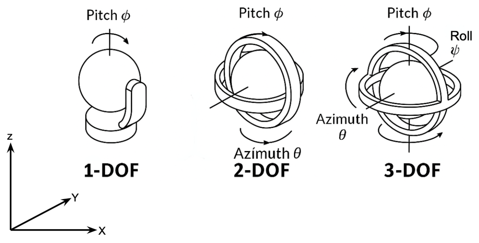
Table 3.
Classification of gimbal achitectures based on DoF.
| Type | DoF | Motion Axes | Application | Power Consumption | Pointing Accuracy | Pros | Cons |
|---|---|---|---|---|---|---|---|
| 1-axis Gimbal | 1-DoF | Pitch or Yaw | fixed-wing UAVs with constrained payload, small high altitude balloons | Low | Moderate | Simple, low-cost | Limited motion, less precise |
| 2-axis Gimbal | 2-DoF | Pitch + Yaw | Multirotors, high-speed beam alignment, airships, stratospheric UAVs | Medium | High | Better Alignment | Medium complexity |
| 3-axis Gimbal | 2-DoF | Pitch+Yaw+ Roll | Advanced UAVs needing roll compensation, satellites, spacecraft, payloads, high-altitude reconnaissance platforms | High | Very High | Full compensation precise | High copmplexity, heavy |
| CubeSat ADCS | Reaction wheels + 2-DoF micro gimbal | Full-body attitude control + fine az/el stage | Cubesats, small satellites (OCSD, AeroCube-7, TBIRD) | Medium | High (sub-mrad) | Low-SWaP integration with ADCS; compact | Limited torque, relies on ADCS stability |
| OPA | Electronics fine steering | Beam steering without mechanics | CubeSats, future smallsat terminals | Low | Very high (micro radian level) | No moving parts, fast response | Limited angular range, optical loss, emerging tech |
| Hexapod | 6-DoF | Translational + Rotational | HAPs, stratospheric airships, vibration isolation platforms | High | High (sub-mrad) | 6-DoF correction, robust to turbulence | Bulky, heavy, high power demand |
In terms of axis coupling, gimbals are divided into two types: mechanically decoupled and nested gimbals. In mechanically decoupled gimbals, each axis has its mechanical frame, i.e., the system consists of two physically separated rotational stages. These systems are easier to model and control because there is less interference between axes. These gimbals are typically larger and are scalable for larger payloads, and also require more precise alignment between stages. They are generally implemented in large ground stations. In nested gimbals, each axis is nested inside another, forming a compact stack, and in the case of 3-DoF, there is also a third ring for roll. These systems are quite compact and lightweight, which makes them easy to deploy on UAV platforms and suitable for platforms with limited payload capacity. But their inverse kinematics and control algorithms make them more complex, and mechanics may limit rotation ranges [46,47]. Table 4 lists the main differences between the two systems.
5.2. Actuation Technologies
The actuation technologies used in gimbal systems, both mechanically decoupled and nested, are based on the required size, weight, power efficiency, performance, and accuracy. Table 5 represents the different actuation technologies used in CPM and FPM [48,49,50,51,52]:
Generally, mechanically decoupled gimbals, for example, gimbals for a ground station, use stepper motors with encoders, DC servo motors (for high torque), harmonic drives (for large payloads), or direct drive motors (for zero backlash and high speed response). While in nested gimbals, mostly BLDC motors with encoders, servo motors + planetary or harmonic gearing, or Piezo actuators are used [46,47].
6. Tracking and Control Algorithms for Coarse Pointing
Coarse pointing modules in FSO-based communication with non-terrestrial platforms require robust control strategies that align the gimbal-mounted beam despite dynamic motion, environmental disturbances, and sensor noise; therefore, they effectively rely on control algorithms. This section examines proportional integral derivative (PID), linear quadratic regulator (LQR), and hybrid approaches like PID & kalman, or LQR & kalman.
6.1. Proportional Integral Derivative (PID):
PID controllers are the most widely used control algorithm in gimbal systems due to their simplicity, ease of implementation, and effectiveness. They control the process variable in the system, which, in the case of gimbals, is the pointing angles. This algorithm efficiently calculates the error/feedback between a desired reference, for example, a target angle or position, and the measured output, for example, gimbal orientation, and then applies the offset action based on proportional (P), integral (I), and derivative (D) terms. Where P reacts to current error, I addresses accumulated past errors, and D predicts future errors based on the rate of change. The Equation (13) represents the mathematical equation of the PID control system in gimbals, where is the angular pointing error. The first term in the equation is P, which generates a torque proportional to the instantaneous pointing error. The second term is I, which cancels steady-state biases (e.g., small misalignment, gravity torques, friction). It must be protected against windup when actuators saturate or during target loss. The third term is D, which adds viscous-like damping, countering the aerial platform’s jitter and structural modes. It improves settling time and reduces overshoot. The derivative action is noise-sensitive and is therefore usually implemented with a first-order filtered differentiator.
In gimbal systems, PID is often applied in a cascaded loop structure, where an outer loop PID controller stabilises the platform’s attitude or position error correction, while an inner loop PID or PI controller controls the motor’s speed or current. In Figure 9 illustrates the cascaded loop structure where the outer position loop (Summing Point 1) outputs a velocity command to inner velocity loop (Summing Point 2) which controls the motor torque.
Although PID is robust and easy to tune, in the case of gimbals for UAVs, it struggles with fast dynamics or non-linearities caused by the aerial platform’s motion or aerodynamic disturbances, especially when there are saturation limits, payload shifts, or sensor drift. Despite this, it remains popular in low-cost and medium-performance applications, particularly for 2-DOF or 3-DOF nested gimbals. For HAPs and stratospheric airships, PID loops are often used as outer control layers to correct slow drifts caused by stratospheric winds, while inner loops rely on more advanced controllers for precision. On the contrary, cubesats rarely rely on PID due to their need for sub-arcsecond pointing, but PID loops are still applied for actuator current or wheel speed regulation [53,54]. In [55], the researcher has implemented a self-tuning PID controller for a two-axis gimbal, enhanced with fuzzy logic and PSO-based gain. Microcontrollers like STM32 or ARM cortex-M, typically executing at loop rates of hundreds to thousands of Hz, are suitable for PID. PID tuning requires manual touch or heuristic, and adaptive methods like fuzzy-PID can mitigate this.
6.2. Linear Quadratic Regulator (LQR):
LQR is a state-space control technique that minimises a quadratic cost function involving system states and control inputs. It is a more optimal and mathematically rigorous alternative to PID, and ideal for systems that are modelled by linear differential equations. In UAV gimbals, the state vector might include angular position, angular velocity, and motor torque. LQR achieves optimal control by minimising a quadratic cost function (Equation (14)) [56]:
Here, x is the state vector, u is the control input, and Q and R are weighting matrices. LQR achieves better trade-offs between performance and control effort compared to PID. It is more valuable in closed-loop coarse pointing, where UAV dynamics and platform disturbances affect gimbal performance. But, its performance decreases with modelling in accuracy and nonlinear regimes. It is also less robust to uncertainties unless combined with estimation techniques like the kalman filter. HAPs and airships are more exposed to large but slow deviations, and LQR is advantageous for minimizing steady control effort over long durations. Cubesats also benefit from LQR when combined with reaction wheels or magnetic torquers, as the quadratic cost framework balances fine pointing precision with limited onboard power resources [53,57].
As LQR demands a linear model and computation of the gain matrix via solving a Riccati equation, it requires embedded platforms with efficient linear algebra, like ARM cortex-M4 or M7, which can handle LQR loops at tens to hundreds of Hz. LQR’s gains tuning can be automated via performance metrics. [58] is not an example of gimbal but a flying wing UAV control that employed LQR with full-state observers to stabilise attitude under disturbances, demonstrating stronger robustness than PID regulation.
6.3. Extended Kalman Filter (EKF):
This kalman-based filter is critical for integrating IMU, GPS, and visual data to form accurate estimates for coarse pointing guidance. It fuses nonlinear, noisy measurements to estimate accurate orientation and angular velocity, which is then sent as feedback control. The EKF linearizes the system dynamics around the current estimate and simultaneously updates state estimates as shown in Equation (15).
Here, are process and measurement noise, and are nonlinear dynamics and measurement models. In [59], the researcher fused IMU, LiDAR SLAM, and visual odometry via an extended kalman filter (EKF) in GPS-denied indoor conditions, validating precise state estimation suitable for coarse pointing control. In terms of computation, EKF requires moderate computation between 100 - 500 Hz update rate and data from sensors such as IMU, GPS, camera, or LiDAR. These systems often run on embedded linux or high-performance microcontrollers with floating-point support. EKF-based estimation is also valuable for cubesats, where fusing star tracker, and gyroscope data ensures accurate attitude determination in orbit. Similarly, in HAPs and stratospheric airships, EKFs are employed to fuse GPS, barometric, and IMU data to mitigate slow drifts and wind-induced offsets, thereby stabilizing long-duration FSO links [53,57].
6.4. Hybrid Approaches PID & Kalman / LQR & Kalman:
Hybrid control algorithms like PID + kalman filter, or LQR + kalman filter, offer a more robust and efficient solution by combining the strengths of classical and optimal control methods with real-time state estimation and noise rejection.
The PID + kalman configuration is used because it has the simplicity of PID and the effectiveness of the kalman filter. In this, PID controllers handle real-time actuation for coarse or fine pointing, while the kalman filter estimates accurate angular velocities and orientations from noisy IMU sensor measurements. These sensor measurements allow the PID loop to respond based on the filtered signals, which in turn reduces overshoot and improves beam stability. This approach is suitable for systems where model precision is limited [60].
In contrast, the LQR + kalman approach offers better performance for well-modelled systems. As LQR minimises a quadratic cost function, balancing control effort and tracking error, the kalman filter estimates the system’s state under noisy conditions. And, together they enable optimal control in dynamic environments [61].
The author in [62] described coarse-fine composite control combining PID and kalman filtering to provide rapid initial alignment with accurate state estimation. These hybrid systems typically run in cascaded loops where an outer kalman filter feeds an inner control loop, either PID or LQR, which requires multi-threaded or co-processor-capable microcontroller stacks. For HAPs and airships, hybrid PID-kalman controllers provide resilience against wind gusts and platform oscillations. However, cubesats often employ LQR-kalman combinations, where state estimation from star trackers and gyros feeds into optimal control laws for precise optical beam alignment. These approaches emphasize long-term stability and robustness over rapid response, contrasting with UAV-based implementations [53,63].
Table 6.
Control algorithms performance comparison.
| Algorithm | Latency/ Bandwidth | Accuracy/ Robustness | Complexity | Hardware Needs |
|---|---|---|---|---|
| PID | High ( 1kHz loops) | Moderate; Sensitive to tuning | Simple | Low-end MCU (e.g., STM32) |
| LQR | Tens to hundreds Hz | Good for modeled systems | Moderate | MCU or small embedded CPU |
| EKF | 100-500 Hz | High accuracy, drift-free fusion | High | MCU + vision/GPS sensors |
| Hybrid (Visual-EKF + LQR) | 100 Hz | Best disturbance rejection & precision | High | STM32 + camera + IMU + GPS |
6.5. Integration of GPS/INS and Visual Tracking:
A hybrid integration, like GPS, INS, and visual tracking with CPMs, provides a robust solution for stabilising and pointing the optical beam. GPS provides global position estimates, while INS delivers high-rate motion data. However, GPS lacks orientation data and also suffers from low update rates, and INS alone drifts over time. Therefore, their combination with EKF enables continuous estimation of position and orientation with low latency and high accuracy, which is crucial for dynamic gimbal control [64]. Systems like Pixhawk flight controller already support GPS/INS integrated tracking for UAV navigation and can share this data with the gimbal controller via MAVLink [65,66]. If the goal is to achieve more precision, combining GPS/INS with vision-based feedback provides a multi-layered, resilient pointing and tracking architecture, which is essential for long-range, high-bandwidth FSO communication. For example, visual tracking can be executed using cameras or quadrant detectors, which contribute to fine pointing by detecting the laser beacon or retro-reflector of the target node. Through this, the system can compensate for residual pointing errors due to wind, vibration, or slight GPS misalignment. Research in [7] on satellite-to-ground FSO links showed that visual beacon tracking can improve pointing accuracy to sub-milliradian levels, which is now being adapted by more researchers for UAV platforms.
7. Challenges in Coarse Pointing
As discussed in the previous sections, the accuracy of steering an optical beam in FSO-based communication with non-terrestrial platforms is fundamentally constrained by the mechanical, environmental, and aerodynamic realities of flight platforms. This section analyses key challenges like mechanical constraints, rotor/vibration dynamics, wind gusts and airflow disturbances, flight manoeuvres, and structural resonance. The review further summarises recent research efforts addressing these challenges.
7.1. Mechanical Constraints and Drive System Limitations:
The mechanical design of gimbal systems, which includes the actuator type used, joint stiffness, and friction, directly affects the achievable pointing accuracy and responsiveness. It is observed that direct-drive BLDC motors eliminate backlash and reflected inertia, but they add weight, cost, and require complex control electronics. By contrast, gear/belt-driven motors are lighter and cheaper but suffer from backlash, hysteresis, and compliance, which lead to degrading repeatability and introduce non-linear torque behaviour. In [67], the researcher modelled gimbal systems including drive friction, structural resonance, and vibration in simulations. The researchers found that high-quality gyros unexpectedly underperformed when resonance and friction were introduced during execution. Also, in some cases, lower-cost sensors yielded better real-world accuracy. The mathematical model for joint compliance can be represented as:
Here, k is joint stiffness, and is friction torque. Also, friction torque may include stribeck effect, and these nonlinearities limit controller bandwidth and increase pointing jitter.
7.2. Vibration and Structural Resonance:
UAVs are rotary platforms, and therefore, they generate structure-borne vibrations due to rotor imbalances, motor torque pulses, and aerodynamic buffeting. In [68], the researcher proposed a combination of passive inertial damping with active inertial dampers to suppress mid-frequency vibrations, while the UAV mount manages high-frequency vibrations. In [69], the researcher demonstrated that time-domain accelerations up to 8.75 g and RMS spectral components exceeding 1.8 g. The researchers implemented a two-stage vibration isolation structure, which reduced gimbal load significantly. Also, one mitigation technique can be using notch filters, as the structural transfer function exhibits peaks at natural frequencies . If the servo control loop bandwidth overlaps resonance, servo instability and degraded pointing occur, and introducing notch filters at resonant frequencies within control loops can improve the system.
7.3. Wind Gusts and Aerodynamic Disturbances:
UAV attitude is also affected by wind gusts and turbulence, which affect roll, pitch, yaw, and translation of the UAV, leading to pointing error if not compensated quickly. The researcher in [70] examined fixed-wing UAVs encountering wind gusts up to 13 m/s. The guidance control prevented runaways and maintained tracking errors below 1m via online wind estimation and control compensation. In [71], the author studied multirotor position control under wind up to 12 m/s using PID and MPC controllers augmented with disturbance estimators (EKF and UKF). MPC with UKF achieved superior disturbance rejection but at a higher computation cost, while, on the contrary, PID was more efficient but less robust at high gust intensities. Mathematically, external disturbance can be represented as :
Controllers must estimate and subtract , and for wind-induced torque , disturbance observer or EKF-based estimation is typical.
7.4. Flight Dynamics and Manoeuvre-Induced Motion:
UAV platforms are used in aerial missions, and due to dynamic environments, they are required to perform high-speed manoeuvres like turns, climbs, and descents, which introduce motion dynamics with high angular rates and accelerations. These manoeuvres produce beam misalignment unless compensated mechanically or via control. In [26], the researcher introduced a 3D pointing error model accounting for roll/pitch/yaw jitter, where they optimised UAV trajectory to reduce alignment exposure during high dynamic flight, achieving up to 11.8% energy efficiency improvement under turbulence conditions compared to gaussian models. In [72], the author provided closed-form channel models incorporating boresight pointing error and turbulence (log-normal and gamma-gamma models). These helped in quantifying link degradation under dynamics and pointing misalignment. The combined jitter variance informs pointing loss via:
The Table 7 summarises the recent research on mitigation strategies based on the problems addressed and solution approach by respective authors in thier research papers.
7.5. Design Recommendations
To mitigate the challenges shared in the above sections, systems must integrate:
- Mechanical Isolation: Hybrid passive/active dampers and notch filters are required to decouple structural vibrations from control loops.
- Drive Selection: Prioritise direct-drive gimbals for performance, but also weigh SWap constraints, and consider high-stiffness, as well as low-friction bearings.
- Disturbance Estimation: EKF observers or disturbance observers running onboard to compensate for wind-induced torque in real time.
- Advanced Control: Predictive or adaptive control algorithms like MPC, fuzzy PID, etc, to react to rapidly changing disturbances and dynamics.
- Trajectory Aware Planning: Co-design of flight path and pointing requirements minimising jitter exposure, for example, launching or descending in end-aligned directions.
- Channel-aware Modelling: Design pointing/divergence margins using statistical models that integrate turbulence and jitter to predict outage probability and capacity.
8. Future Directions and Open Research Questions
As FSO links mature across non-terrestrial platforms (satellites, HAPS, and UAVs), emerging trends such as terminal miniaturisation, AI-based predictive APT, optical phased-array/MEMS beam steering, and cooperative multi-platform coordination (e.g., UAV swarms with satellite backhaul) signal a strong pathway to scalable, secure 6G NTN deployments. These advances promise higher link availability and capacity with lower SWaP, enabling resilient space–air–ground networks for next-generation services. This section explores these directions with scientific depth and also highlights key open research challenges.
Miniaturisation is critical for integrating FSO communication systems into micro and nano-UAVs, which operate under stringent size, weight, and power (SWaP) constraints. In such platforms, APT mechanisms must be not only compact and lightweight but also highly reliable and accurate. Passive solutions such as retroreflectors or other non-mechanical modules offer ultra-low SWaP footprints. But they inherently lack the capability for active beam steering, which is essential for maintaining precise optical alignment in dynamic flight conditions. Therefore, recent advances in fine steering technologies, such as micro-electromechanical systems (MEMS) based fast steering mirrors (FSMs) or LiDAR-inspired mechanisms, demonstrate promising capabilities, with units achieving sub-microradian resolution over angular ranges of , and they also weigh less than 40 grams. Despite these advancements, a major challenge persists in integrating such mechanisms with miniaturised gimbals, particularly those under 500 grams, which can maintain the required stiffness and structural stability during UAV aerial missions. Also, some notable efforts have been made in the development of compact gimbal assemblies for high-altitude pseudo-satellites like the olympic HAPS platform, and cube-satellite payloads, illustrating the feasibility of lightweight FSO tracking modules. But, further miniaturisation will require a co-optimisation approach, targeting enhancements in both actuator torque density and mechanical stiffness to ensure performance without compromising SWaP limitations [73,74,75].
Now, coarse pointing relies on reactive sensor feedback, sensors like GPS/IMU inputs, encoders, or visual cues. These inputs introduce latency in the pointing and tracking system. In contrast, predictive pointing schemes proactively forecast the future position of the target to pre-steer the beam, thereby significantly reducing alignment delay. In [76], the researcher introduced an LSTM-based recurrent neural network (LRNet) that learns from prior UAV trajectory data to predict subsequent UAV positions. Although their study focused on RF beamforming, the same concept can readily be extended to FSO systems, where fine angular precision is critical. In another paper [77], the researcher explored multi-agent deep reinforcement learning (MARL) to jointly optimise UAV trajectories and relay link selection in hybrid RF/FSO networks. This approach helped in achieving nearly two times higher end-to-end throughput and greater energy efficiency. The mathematical insight shared in Equation (19) shows that predictive pointing reduces error delay by anticipating motion.
Another promising avenue for investigation is UAV swarms. As UAV swarms have become a viable solution, a mission requires cooperative actions like relay networks and mesh communication. Therefore, coarse pointing control can evolve to support multi-agent coordination and seamless beam pointing. A variety of swarm formation-control frameworks have been proposed, like sliding-mode control augmented with artificial potential functions, which provide robust inter-UAV positioning, collision avoidance, and maintenance of formation integrity [78,79]. Also, distributed nonlinear model predictive control schemes like those using consensus-based and directed graph formulation can enable decentralised trajectory planning and inter-UAV collision avoidance under dynamic constraints [80,81]. And, within RIS-equipped swarm architectures, the optimisation of collective phase-shift settings and UAV trajectories aims to minimise aggregate pointing error across the formation, enabling coordinated FSO pointing with high precision under atmospheric disturbances [23]. The Equations (20) and (21) represent the mathematical constructs of consensus constraints that enforce alignment and swarm optimisation objective, respectively.
where is the pointing loss term for UAV i, and penalises misalignment between neighbours.
Another promising research direction is the development of hybrid RF-optical communication architectures for non-terrestrial platforms. Since FSO links are highly sensitive to pointing errors, turbulence, and weather-induced outages, integrating an RF control or backup channel can substantially improve link availability. In such systems, the RF link provides robust, wide-FoV acquisition and coarse pointing information (position, timing, or beacon aid), while the optical link carries the high-capacity data stream. This synergy enables continuous service under cloud blockage or temporary misalignment, with the RF channel seamlessly taking over or assisting beam reacquisition. Hybrid integration has already been explored in satellite-ground links and UAV swarm coordination, showing improvements in both link reliability and handover efficiency. Alongside this hybrid RF-optical control mechanism is also an important emerging paradigm. In this approach, RF beams with wide divergence are first used for coarse acquisition and initial alignment between aerial platforms and ground stations. Once coarse pointing is achieved, the system transitions to a narrow-beam optical link for fine pointing and tracking. This layered acquisition approach minimizes mechanical gimbal burden, reduces complexity, and enhances system reliability in turbulent environments. In Figure 10, is illustrating two stages of a hybrid RF-FSO acquisition process. At stage 1 which is coarse acquisition the cone shaped RF beam from the aerial platform and ground station establishing an initial link . Then at stage 2, which is fine tracking and data transmission a focused FSo beam is precisely pointed towards the aerial platform indicating that the RF link has handed over control.
Future UAV, HAP, and cubesat networks are expected to adopt such dual-mode terminals, potentially combining mmWave/Thz RF for acquisition with optical phased arrays or MEMS-based optics for data transport. While some open questions remain around joint resource allocation, cross-layer optimization, and hardware miniaturization of dual-mode payloads under SWap constraints [5,82,83,84].
9. Conclusion
In this survey, the paper explored state-of-the-art in coarse and fine pointing mechanisms, especially gimbal architectures for FSO systems deployed on and for non-terrestrial platforms. FSO technology offers unparalleled data rates, immunity to electromagnetic interference, and compactness, making it a strong candidate for high-throughput aerial communication. However, the narrow beam divergence, which is inherent to optical links, makes them more critical to misalignment, and, therefore, makes robust pointing and tracking subsystems more crucial for FSO systems.
The paper first established a technical foundation by exploring the fundamentals of FSO communication in aerial platforms, emphasising how the dynamics of non-terrestrial platforms introduce new challenges for maintaining a stable LoS. Then it provided a detailed differentiation between coarse and fine pointing systems for FSO, including their respective roles in beam acquisition and tracking. Coarse pointing is typically achieved using gimbal systems and provides initial alignment to bring the target within the field of view (FoV) of the fine pointing systems, which then handle micro-level corrections. Through mathematical models and optical equations, the respective sections demonstrated the complementary nature of these two subsystems and their joint importance in achieving high pointing accuracy and system reliability.
The paper reviews gimbal architectures, including nested-frame, stabilised-platform, and hybrid designs. It analyses trade-offs in payload capacity, pointing precision, stabilisation effectiveness, and power efficiency. The literature survey compares more than fifteen recent systems across angular resolution, response time, control bandwidth, and payload-integration metrics, providing a clear map of current capabilities.
On the algorithmic front, the paper examined common control strategies such as PID, LQR, kalman filters, and advanced sensor fusion with GPS/INS, and vision systems. Each approach presents different trade-offs in responsiveness, stability, and computational complexity. A recent research has implemented hybrid PID-Kalman and LQR-EKF controllers, which displayed more enhanced disturbance rejection and tracking fidelity in gimbal systems. Several control algorithms were tied directly to recent UAV pointing systems, illustrating real-world relevance and performance results. Hardware platforms ranging from low to high computational power required for respective control algorithms were also discussed, concerning specific requirements.
The paper also addressed the pressing challenges encountered in coarse pointing of non-terrestrial platforms, including platform vibrations, mechanical constraints, wind gusts, and flight path instability. These factors introduce dynamic uncertainties that degrade pointing accuracy, especially in lightweight drone platforms. Research efforts involving vibration isolation and adaptive filtering have shown promising results in mitigating these challenges.
At the end, the paper explored future directions related to the miniaturisation of gimbal platforms, AI-based predictive tracking models, and integration with UAV swarming protocols. These innovations look affirmative in redefining the scalability, autonomy, and resilience of FSO links in next-generation aerial networks. Open research challenges remain in multi-axis stabilisation under turbulent flow, long-duration LOS stability under high UAV mobility, and resource-optimised control strategies that can balance precision and energy efficiency.
From a system design perspective, the most effective stack for building a high-performance CPM for FSO-based communication with aerial platforms shall combine high-torque density BLDC motors with dual-axis direct-drive gimbal architectures to minimise backlash and mechanical delays. Control-wise, a hybrid approach combining MPC for trajectory foresight and EKF for sensor fusion offers superior tracking accuracy in dynamic aeria conditions. Incorporating adaptive control logic ensures resilience in dynamic aerial conditions. Incorporating adaptive control logic ensures resilience to changing payloads and external disturbances like wind gusts. For sensory inputs, a tight integration of GPS/INS with visual inertial odometry (VIO) enables accurate localisation even under GNSS-challenged environments. To future-proof the system, onboard deployment of lightweight AI models, especially LSTM or transformer-based trajectory predictors, can preemptively adjust pointing, reducing response lag during fast manoeuvres. Looking ahead, further research must focus on graph-based swarm pointing coordination and modular software architectures that allow plug-and-play integration of future sensors and AI models. This cohesive and reliable stack sets the foundation for agile, scalable, and autonomous FSO networks operating across complex aerial domains. In conclusion, CPMs or gimbals are the backbone of reliable FSO communication on non-terrestrial platforms for 6G communication. Building on recent progress, the continued convergence of lightweight materials, adaptive control, AI, and system integration will set the course for this critical technology. As aerial platforms evolve into more autonomous and collaborative systems, the demand for resilient, low-power, and ultra-precise pointing mechanisms will continue to rise.
References
- Gupta, L.; Jain, R.; Vaszkun, G. Survey of important issues in UAV communication networks. IEEE communications surveys & tutorials 2015, 18, 1123–1152. [Google Scholar]
- Li, B.; Fei, Z.; Zhang, Y. UAV communications for 5G and beyond: Recent advances and future trends. IEEE Internet of Things Journal 2018, 6, 2241–2263. [Google Scholar] [CrossRef]
- Kaushal, H.; Jain, V.; Kar, S. Free space optical communication; Vol. 60, Springer, 2017.
- Hemmati, H. Near-earth laser communications. In Near-Earth Laser Communications, Second Edition; CRC press, 2020; pp. 1–40.
- Khalighi, M.A.; Uysal, M. Survey on free space optical communication: A communication theory perspective. IEEE communications surveys & tutorials 2014, 16, 2231–2258. [Google Scholar]
- Mondal, A.; Hossain, A. Channel characterization and performance analysis of unmanned aerial vehicle-operated communication system with multihop radio frequency–free-space optical link in dynamic environment. International Journal of communication systems 2020, 33, e4568. [Google Scholar] [CrossRef]
- Toyoshima, M.; Kuri, T.; Werner, K.; Toyoda, M.; Takenaka, H.; Shoji, Y.; Takayama, Y.; Koyama, Y.; Kunimori, H.; Jono, T.; et al. Overview of the laser communication system for the NICT optical ground station and laser communication experiments on ground-to-satellite links. Journal of the National Institute of Information and Communications Technology 2012, 59, 053–075. [Google Scholar]
- Chaudhary, H.; Khatoon, S.; Singh, R.; Pandey, A. Fast steering mirror for optical fine pointing applications: A review paper applications: A review paper. 2018 3rd International Innovative Applications of Computational Intelligence on Power, Energy and Controls with their Impact on Humanity (CIPECH) 2018, pp. 1–5.
- Harris, A.; Sluss, J.J.; Refai, H.H.; LoPresti, P.G. Alignment and tracking of a free-space optical communications link to a UAV. In Proceedings of the 24th Digital Avionics Systems Conference. IEEE, 2005, Vol. 1, pp. 1–C.
- Giggenbach, D.; Horwath, J. Optical free-space communications downlinks from stratospheric platforms-overview on stropex, the optical communications experiment of capanina. IST Summit Dresden 2005. [Google Scholar]
- Cap, G.A.; Refai, H.H.; Sluss, J.J., Jr. FSO tracking and auto-alignment transceiver system. In Proceedings of the Unmanned/unattended sensors and sensor networks V. SPIE, 2008, Vol. 7112, pp. 71–82.
- Locke, M.; Czarnomski, M.; Qadir, A.; Setness, B.; Baer, N.; Meyer, J.; Semke, W.H. High-performance two-axis gimbal system for free space laser communications onboard unmanned aircraft systems. In Proceedings of the Free-Space Laser Communication Technologies XXIII. SPIE; 2011; Vol. 7923, pp. 141–148. [Google Scholar]
- Carrasco-Casado, A.; Vergaz, R.; Pena, J.M.S. Design and early development of a UAV terminal and a ground station for laser communications. In Proceedings of the Unmanned/unattended sensors and sensor networks VIII. SPIE; 2011; Vol. 8184, pp. 89–97. [Google Scholar]
- Talmor, A.G.; Harding Jr, H.; Chen, C.C. Two-axis gimbal for air-to-air and air-to-ground laser communications. In Proceedings of the Free-Space Laser Communication and Atmospheric Propagation XXVIII. SPIE; 2016; Vol. 9739, pp. 129–135. [Google Scholar]
- Rowen, D.; Dolphus, R.; Doyle, P.; Faler, A. OCSD-A/AeroCube-7: A Status Update. In Proceedings of the 13th Cal Poly CubeSat Developer’s Workshop, San Luis Obispo, CA, Apr; 2016; pp. 20–22. [Google Scholar]
- Welle, R.; Venturini, C.; Hinkley, D.; Gangestad, J.; Bellardo, J.; Johnson, P.; Rowen, D. On-Orbit Results of the AeroCube-10 Mission: Proximity Operations and In-Space Inspection. In Proceedings of the 34th Annual AIAA/USU Conference on Small Satellites. Utah State University; 2020. SSC20-III-01. [Google Scholar]
- Safi, H.; Dargahi, A.; Cheng, J. Spatial beam tracking and data detection for an FSO link to a UAV in the presence of hovering fluctuations. arXiv 2019, arXiv:1904.03774. [Google Scholar] [CrossRef]
- Safi, H.; Dargahi, A.; Cheng, J. Beam tracking for UAV-assisted FSO links with a four-quadrant detector. IEEE Communications Letters 2021, 25, 3908–3912. [Google Scholar] [CrossRef]
- Liu, Z.; Zhang, F.; Hong, X. Low-Cost Retina-Like Robotic Lidars Based on Incommensurable Scanning. IEEE/ASME Transactions on Mechatronics 2022, 27, 58–68. [Google Scholar] [CrossRef]
- Wang, J.Y.; Ma, Y.; Lu, R.R.; Wang, J.B.; Lin, M.; Cheng, J. Hovering UAV-based FSO communications: Channel modelling, performance analysis, and parameter optimization. IEEE Journal on Selected Areas in Communications 2021, 39, 2946–2959. [Google Scholar] [CrossRef]
- Kang, X.; Herrera, A.; Lema, H.; Valencia, E.; Vandewalle, P. Adaptive sampling-based particle filter for visual-inertial gimbal in the wild. arXiv 2022, arXiv:2206.10981. [Google Scholar]
- Ge, H.; Dong, K.; An, Y.; Gao, L.; Li, X. Joint channel model of unmanned aerial vehicle laser communication based on Hoyt distribution. Chinese Journal of Lasers 2023, 50, 1106004. [Google Scholar] [CrossRef]
- Jia, H.; Chen, G.; Huang, C.; Dang, S.; Chambers, J.A. Trajectory and phase shift optimization for RIS-equipped UAV in FSO communications with atmospheric and pointing error loss. Electronics 2023, 12, 4275. [Google Scholar] [CrossRef]
- National Aeronautics and Space Administration. OCSD Project. https://www.nasa.gov/smallspacecraft/ocsd-project/, 2025. Accessed: 2025-08-28.
- Schieler, C.M.; Riesing, K.M.; Bilyeu, B.C.; Chang, J.S.; Garg, A.S.; Gilbert, N.J.; Horvath, A.J.; Reeve, R.S.; Robinson, B.S.; Wang, J.P.; et al. On-orbit demonstration of 200-Gbps laser communication downlink from the TBIRD CubeSat. In Proceedings of the Free-Space Laser Communications XXXV. SPIE; 2023; Vol. 12413, p. 1241302. [Google Scholar]
- Moon, H.J.; Chae, C.B.; Wong, K.K.; Alouini, M.S. A generalized pointing error model for FSO links with fixed-wing UAVs for 6G: Analysis and trajectory optimization. IEEE Transactions on Wireless Communications 2025. [Google Scholar] [CrossRef]
- Abdelfatah, R.; Alshaer, N.; Ismail, T. A review on pointing, acquisition, and tracking approaches in UAV-based FSO communication systems. Optical and Quantum Electronics 2022, 54, 571. [Google Scholar] [CrossRef]
- Petkovic, M.; Narandzic, M. Overview of UAV based free-space optical communication systems. In Proceedings of the International Conference on Interactive Collaborative Robotics. Springer; 2019; pp. 270–277. [Google Scholar]
- Leitgeb, E.; Zettl, K.; Muhammad, S.S.; Schmitt, N.; Rehm, W. Investigation in free space optical communication links between unmanned aerial vehicles (UAVs). In Proceedings of the 2007 9th international conference on transparent optical networks. IEEE; 2007; Vol. 3, pp. 152–155. [Google Scholar]
- Andrews, L.C.; Beason, M.K. Laser beam propagation in random media: new and advanced topics; 2023.
- Elsayed, E.E. Investigations on OFDM UAV-based free-space optical transmission system with scintillation mitigation for optical wireless communication-to-ground links in atmospheric turbulence. Optical and Quantum Electronics 2024, 56, 837. [Google Scholar] [CrossRef]
- Takahashi, K.; Arimoto, Y. Compact optical antennas using free-form surface optics for ultrahigh-speed laser communication systems. Optical Engineering 2008, 47, 016002–016002. [Google Scholar] [CrossRef]
- Mohan, S.; Alvarez-Salazar, O.; Birnbaum, K.; Biswas, A.; Farr, W.; Hemmati, H.; Johnson, S.; Ortiz, G.; Quirk, K.; Rahman, Z.; et al. Pointing, acquisition, and tracking architecture tools for deep-space optical communications. In Proceedings of the Free-Space Laser Communication and Atmospheric Propagation XXVI. SPIE; 2014; Vol. 8971, pp. 112–122. [Google Scholar]
- Fidler, F.; Knapek, M.; Horwath, J.; Leeb, W.R. Optical communications for high-altitude platforms. IEEE Journal of selected topics in quantum electronics 2010, 16, 1058–1070. [Google Scholar] [CrossRef]
- Locke, M.; Czarnomski, M.; Qadir, A.; Setness, B.; Baer, N.; Meyer, J.; Semke, W.H. High-performance two-axis gimbal system for free space laser communications onboard unmanned aircraft systems. In Proceedings of the Free-Space Laser Communication Technologies XXIII. SPIE; 2011; Vol. 7923, pp. 141–148. [Google Scholar]
- Ren, W.; Qiao, Q.; Nie, K.; Mao, Y. Robust DOBC for stabilization loop of a two-axes gimbal system. IEEE Access 2019, 7, 110554–110562. [Google Scholar] [CrossRef]
- Cui, Y.; Zhu, Y.; Liu, J.; Wang, C.; Zhao, L. Analysis, Estimation, and Rejection of Multi-Frequency Unknown Disturbances in CMG Gimbal Servo Systems. IEEE Transactions on Circuits and Systems II: Express Briefs 2024, 71, 4501–4505. [Google Scholar] [CrossRef]
- Carrasco-Casado, A.; Shiratama, K.; Trinh, P.V.; Kolev, D.; Ishola, F.; Fuse, T.; Tsuji, H.; Toyoshima, M. NICT’s versatile miniaturized lasercom terminals for moving platforms. In Proceedings of the 2022 IEEE International Conference on Space Optical Systems and Applications (ICSOS); 2022; pp. 213–217. [Google Scholar] [CrossRef]
- Graham, C.; Bramall, D.; Younus, O.; Riaz, A.; Binns, R.; Scullion, E.; Wicks, R.T.; Bourgenot, C. Steering mirror system with closed-loop feedback for free-space optical communication terminals. Aerospace 2024, 11, 330. [Google Scholar] [CrossRef]
- CubeSpace. Gen2 CubeStar Miniature Star Tracker. https://satsearch.co/products/cubespace-gen2-cubestar-miniature-star-tracker, 2024. Accessed on: 2024-08-9.
- Ding, J.; Mei, H.; I, C.L.; Zhang, H.; Liu, W. Frontier progress of unmanned aerial vehicles optical wireless technologies. Sensors 2020, 20, 5476. [Google Scholar] [CrossRef]
- Kaymak, Y.; Rojas-Cessa, R.; Feng, J.; Ansari, N.; Zhou, M.; Zhang, T. A Survey on Acquisition, Tracking, and Pointing Mechanisms for Mobile Free-Space Optical Communications. IEEE Communications Surveys & Tutorials 2018, 20, 1104–1123. [Google Scholar] [CrossRef]
- Carrasco-Casado, A.; Vergaz, R.; Pena, J.M.S. Design and early development of a UAV terminal and a ground station for laser communications. In Proceedings of the Unmanned/unattended sensors and sensor networks VIII. SPIE; 2011; Vol. 8184, pp. 89–97. [Google Scholar]
- Majumdar, A.K. Advanced free space optics (FSO): a systems approach; Vol. 186, Springer, 2014.
- Eguri, S.V.K.; Raj A, A.B.; Sharma, N. Survey on acquisition, tracking and pointing (ATP) systems and beam profile correction techniques in FSO communication systems. Journal of Optical Communications 2024, 45, 881–904. [Google Scholar] [CrossRef]
- Hemmati, H. Deep space optical communications; John Wiley & Sons, 2006.
- Kaushal, H.; Kaddoum, G. Optical communication in space: Challenges and mitigation techniques. IEEE communications surveys & tutorials 2016, 19, 57–96. [Google Scholar]
- Truex, T.; Bent, A.A.; Hagood, N.W. Beam steering optical switch fabric utilizing piezoelectric actuation technology. In Proceedings of the Proc. NFOEC; 2003. [Google Scholar]
- Li, Q.; Liu, L.; Ma, X.; Chen, S.L.; Yun, H.; Tang, S. Development of multitarget acquisition, pointing, and tracking system for airborne laser communication. IEEE Transactions on Industrial Informatics 2018, 15, 1720–1729. [Google Scholar] [CrossRef]
- Ke, C.; Shu, Y.; Ke, X.; Han, M.; Chen, R. Design and implementation of a non-common-view axis alignment system for airborne laser communication. In Proceedings of the Photonics. MDPI; 2023; Vol. 10, p. 1037. [Google Scholar]
- Li, X.M.; Zhang, L.z.; Meng, L.X. Airborne space laser communication system and experiments. In Proceedings of the Selected Papers of the Photoelectronic Technology Committee Conferences held June–July 2015. SPIE; 2015; Vol. 9795, pp. 98–108. [Google Scholar]
- Lahari, S.A.; Raj, A.; Soumya, S. Control of fast steering mirror for accurate beam positioning in FSO communication system. In Proceedings of the 2021 International Conference on System, Computation, Automation and Networking (ICSCAN). IEEE, 2021, pp. 1–6.
- Bednarski, S.T. CubeSat attitude determination and control system (ADACS) characterization and testing for rendezvous and proximity operations (RPO) 2021.
- Wikipedia contributors. High-altitude platform station — Wikipedia, The Free Encyclopedia, 2025. [Online; accessed 9-August-2025].
- Şahin, M. Stabilization of Two Axis Gimbal System with Self Tuning PID Control. Politeknik Dergisi 2023, pp. 1–1.
- Maaruf, M.; Mahmoud, M.S.; Ma’arif, A. A survey of control methods for quadrotor uav. International Journal of Robotics and Control Systems 2022, 2, 652–665. [Google Scholar] [CrossRef]
- Safi, H.; Dargahi, A.; Cheng, J.; Safari, M. Analytical channel model and link design optimization for ground-to-HAP free-space optical communications. Journal of Lightwave Technology 2020, 38, 5036–5047. [Google Scholar] [CrossRef]
- Panomrattanarug, B.; Higuchi, K.; Mora-Camino, F. Attitude control of a quadrotor aircraft using LQR state feedback controller with full order state observer. In Proceedings of the The SICE Annual Conference 2013. IEEE, 2013, pp. 2041–2046.
- Marković, L.; Kovač, M.; Milijas, R.; Car, M.; Bogdan, S. Error state extended kalman filter multi-sensor fusion for unmanned aerial vehicle localization in gps and magnetometer denied indoor environments. In Proceedings of the 2022 International Conference on Unmanned Aircraft Systems (ICUAS). IEEE; 2022; pp. 184–190. [Google Scholar]
- Wakitani, S.; Nakanishi, H.; Ashida, Y.; Yamamoto, T. Study on a Kalman filter based PID controller. IFAC-PapersOnLine 2018, 51, 422–425. [Google Scholar] [CrossRef]
- Gómez Gómez, J.A.; Moncada Guayazán, C.E.; Roa Prada, S.; Gonzalez Acevedo, H. Design and Experimental Validation of a LQG Control System for the Stabilization of a 2DOF Commercial Gimbal Using Physical Modelling Techniques. In Proceedings of the ASME International Mechanical Engineering Congress and Exposition. American Society of Mechanical Engineers, 2020, Vol. 84546, p. V07AT07A019.
- Liu, Y. Review of self-stabilization algorithms in UAV electro-optical pods. Applied Computational Engineering 2024, 93, 56–60. [Google Scholar] [CrossRef]
- Wikipedia contributors. Spacecraft attitude determination and control — Wikipedia, The Free Encyclopedia, 2025. [Online; accessed 31-August-2025].
- Farrell, J. Aided navigation: GPS with high rate sensors; McGraw-Hill, Inc., 2008.
- ArduPilot Developers. Extended Kalman Filter (EKF) – The ArduPilot Developer Guide, 2024. Accessed on August 9, 2024.
- MAVLink Developers. Gimbal Protocol v2 – MAVLink Documentation, 2024. Accessed on August 9, 2024.
- Jia, R.; Nandikolla, V.K.; Haggart, G.; Volk, C.; Tazartes, D. System performance of an inertially stabilized gimbal platform with friction, resonance, and vibration effects. Journal of Nonlinear Dynamics 2017, 2017, 6594861. [Google Scholar] [CrossRef]
- Brake, N.J. Control system development for small uav gimbal. Master’s thesis, California Polytechnic State University, 2012.
- Xu, G.; Yu, Z.; Liu, G. Research of the single-rotor UAV gimbal vibration test. The Journal of Engineering 2023, 2023, e12306. [Google Scholar] [CrossRef]
- Stastny, T.; Siegwart, R. On flying backwards: Preventing run-away of small, low-speed, fixed-wing UAVs in strong winds. In Proceedings of the 2019 IEEE/RSJ international conference on intelligent robots and systems (IROS). IEEE; 2019; pp. 5198–5205. [Google Scholar]
- Hentzen, D.; Stastny, T.; Siegwart, R.; Brockers, R. Disturbance estimation and rejection for high-precision multirotor position control. In Proceedings of the 2019 IEEE/RSJ International Conference on Intelligent Robots and Systems (IROS). IEEE; 2019; pp. 2797–2804. [Google Scholar]
- Dabiri, M.T.; Rezaee, M.; Ansari, I.S.; Yazdanian, V. Channel modeling for UAV-based optical wireless links with nonzero boresight pointing errors. IEEE Transactions on Vehicular Technology 2020, 69, 14238–14246. [Google Scholar] [CrossRef]
- Park, S.; Yeo, C.I.; Heo, Y.S.; Ryu, J.H.; Kang, H.S.; Lee, D.S.; Jang, J.H. Tracking efficiency improvement according to incident beam size in QPD-based PAT system for common path-based full-duplex FSO terminals. Sensors 2022, 22, 7770. [Google Scholar] [CrossRef]
- Nzekwu, N.J.; Fernandes, M.A.; Fernandes, G.M.; Monteiro, P.P.; Guiomar, F.P. A comprehensive review of uav-assisted fso relay systems. In Proceedings of the Photonics. MDPI; 2024; Vol. 11, p. 274. [Google Scholar]
- Luo, D.; Xiong, X.; Chen, W.; Huang, R. Design of two-dimensional piezoelectric laser scanner system for precision laser beam steering. Review of Scientific Instruments 2023, 94. [Google Scholar] [CrossRef]
- Liu, C.; Yuan, W.; Wei, Z.; Liu, X.; Ng, D.W.K. Location-aware predictive beamforming for UAV communications: A deep learning approach. IEEE Wireless Communications Letters 2020, 10, 668–672. [Google Scholar] [CrossRef]
- Lee, J.H.; Park, J.; Bennis, M.; Ko, Y.C. Integrating LEO satellites and multi-UAV reinforcement learning for hybrid FSO/RF non-terrestrial networks. IEEE Transactions on Vehicular Technology 2022, 72, 3647–3662. [Google Scholar] [CrossRef]
- Wikipedia contributors. Sliding mode control, 2025. Accessed: 2025-08-08.
- Han, K.; Lee, J.; Kim, Y. Unmanned aerial vehicle swarm control using potential functions and sliding mode control. Proceedings of the Institution of Mechanical Engineers, Part G: Journal of Aerospace Engineering 2008, 222, 721–730. [Google Scholar] [CrossRef]
- Wang, Y.; Fang, Y.; Mei, J.; Gong, Y.; Ma, G. Nonlinear Model Predictive Control for Leaderless UAV Formation Flying with Collision Avoidance under Directed Graphs. arXiv 2025, arXiv:2505.06895. [Google Scholar] [CrossRef]
- Pang, Q.; Zhu, Y.; Chen, Y.; Wang, D.; Suo, W. UAV formation control based on distributed Kalman model predictive control algorithm. AIP Advances 2022, 12. [Google Scholar] [CrossRef]
- Mohamed, A.; Celik, A.; Yanikomeroglu, H. Hybrid RF/FSO UAV Communication Links for Beyond-5G Networks. IEEE Access 2021, 9, 115472–115490. [Google Scholar]
- Kaushal, H.; Kaddoum, G. Optical and RF Hybrid FSO Communication Systems: A Survey. IEEE Communications Surveys & Tutorials 2017, 19, 3097–3131. [Google Scholar]
- Ciaramella, E.; Arimoto, Y.; Contestabile, G.; Presi, M.; D’Errico, A.; Guarino, V.; Matsumoto, M. 1.28 Tb/s Transmission in a Single-Channel Free-Space Optical Link. Journal of Lightwave Technology 2010, 28, 2333–2339. [Google Scholar]
Figure 1.
Challenges during FSO-based communication with UAVs.
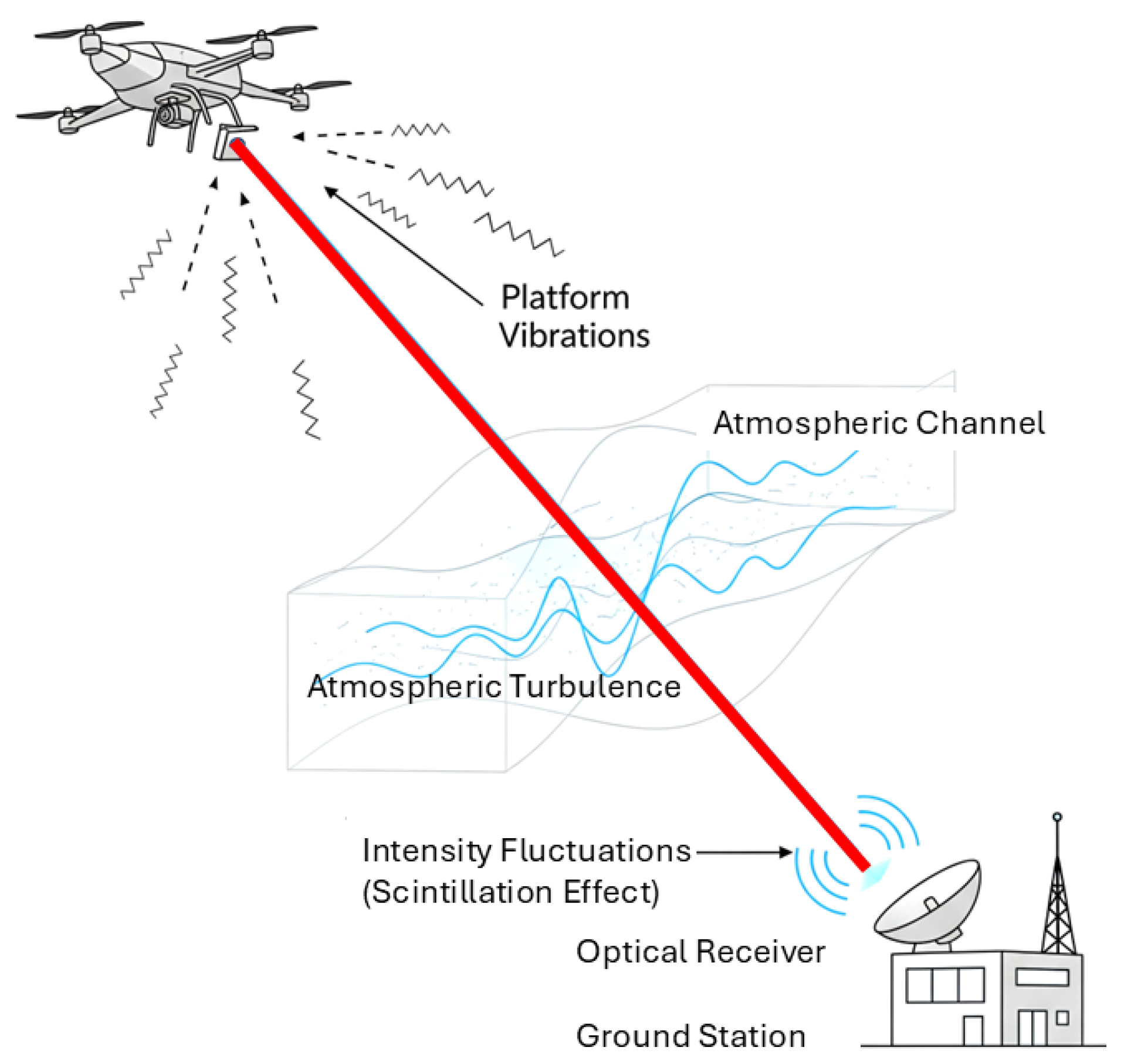
Figure 2.
Gimbal module used for communication with aerial platforms.
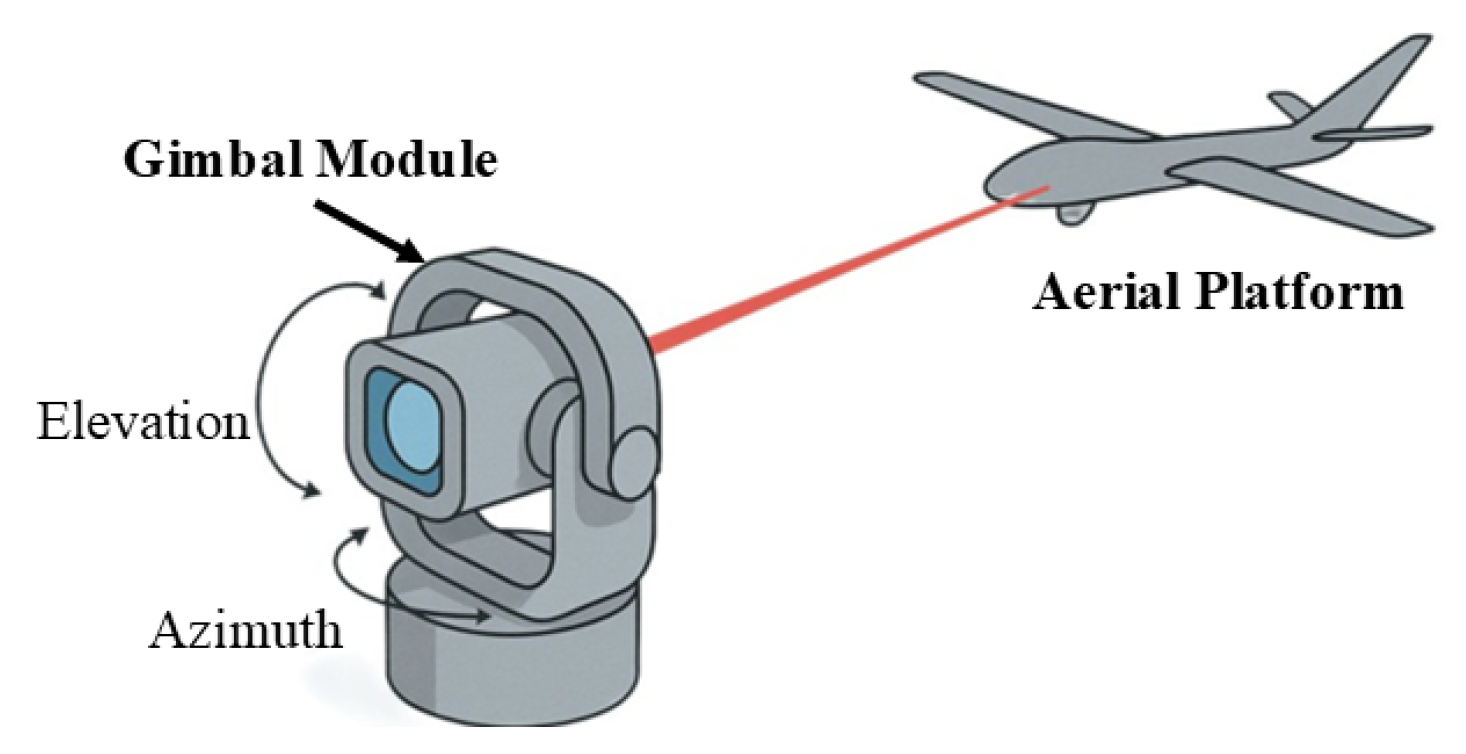
Figure 3.
Optical downlink concept for the TBIRD CubeSat [25].
Figure 3.
Optical downlink concept for the TBIRD CubeSat [25].
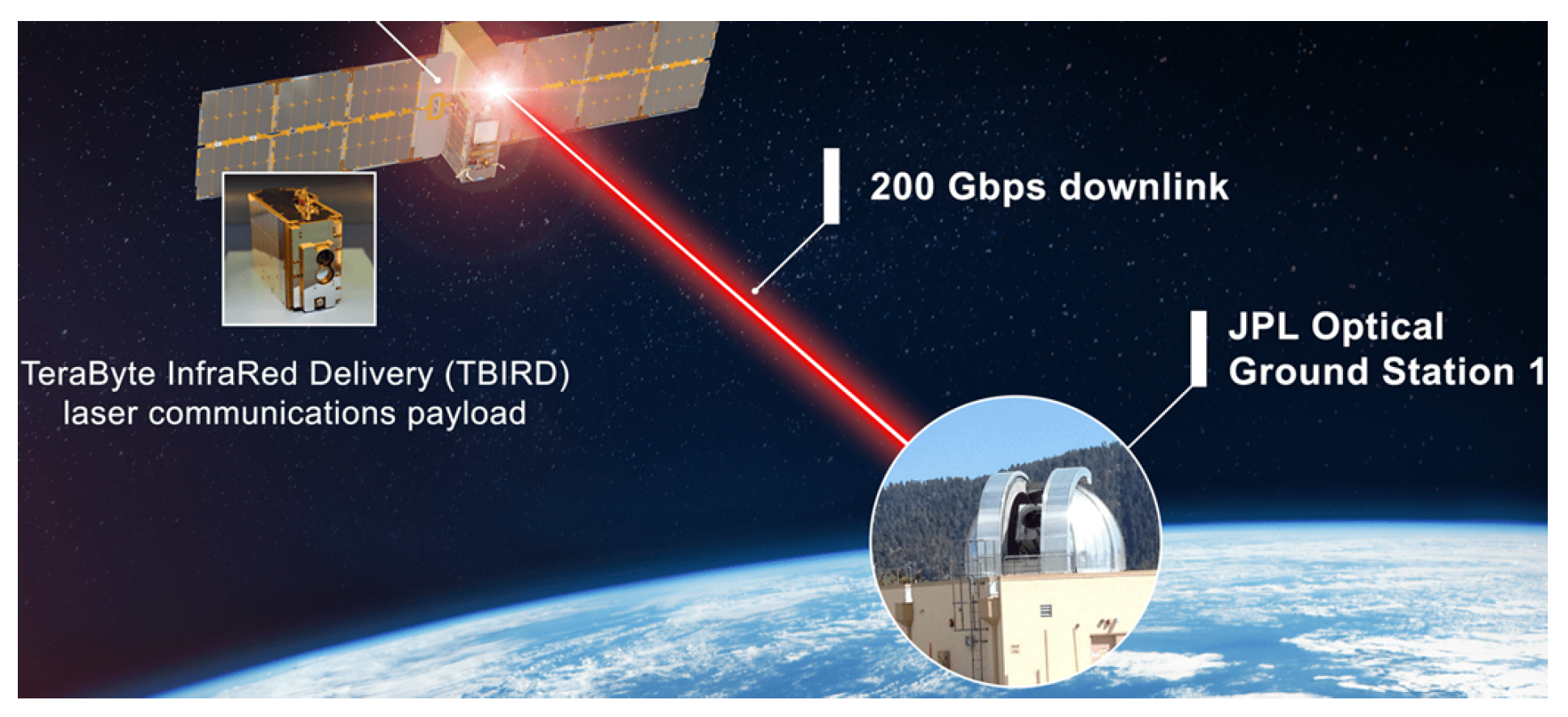
Figure 4.
FSO link budget visualisation.
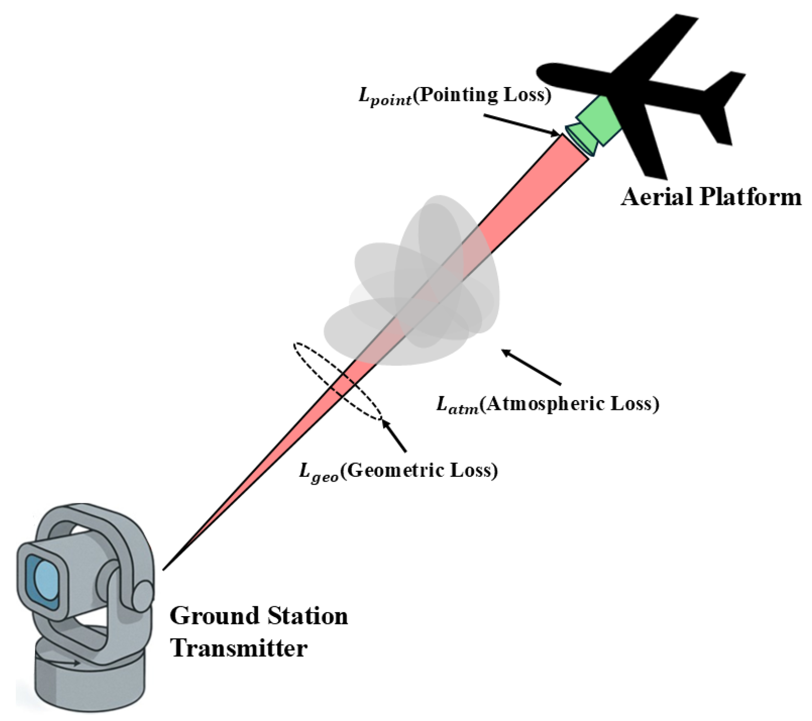
Figure 5.
Basic geometrical representation of gimbal system.
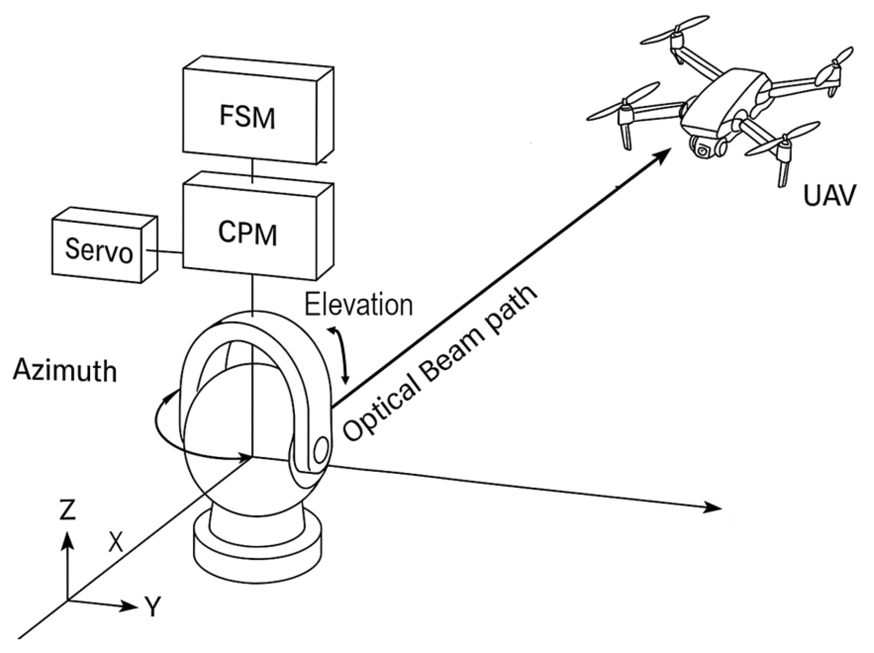
Figure 6.
(a) Mechanical gimbal for coarse pointing. (b) MEMS mirror for fine pointing.
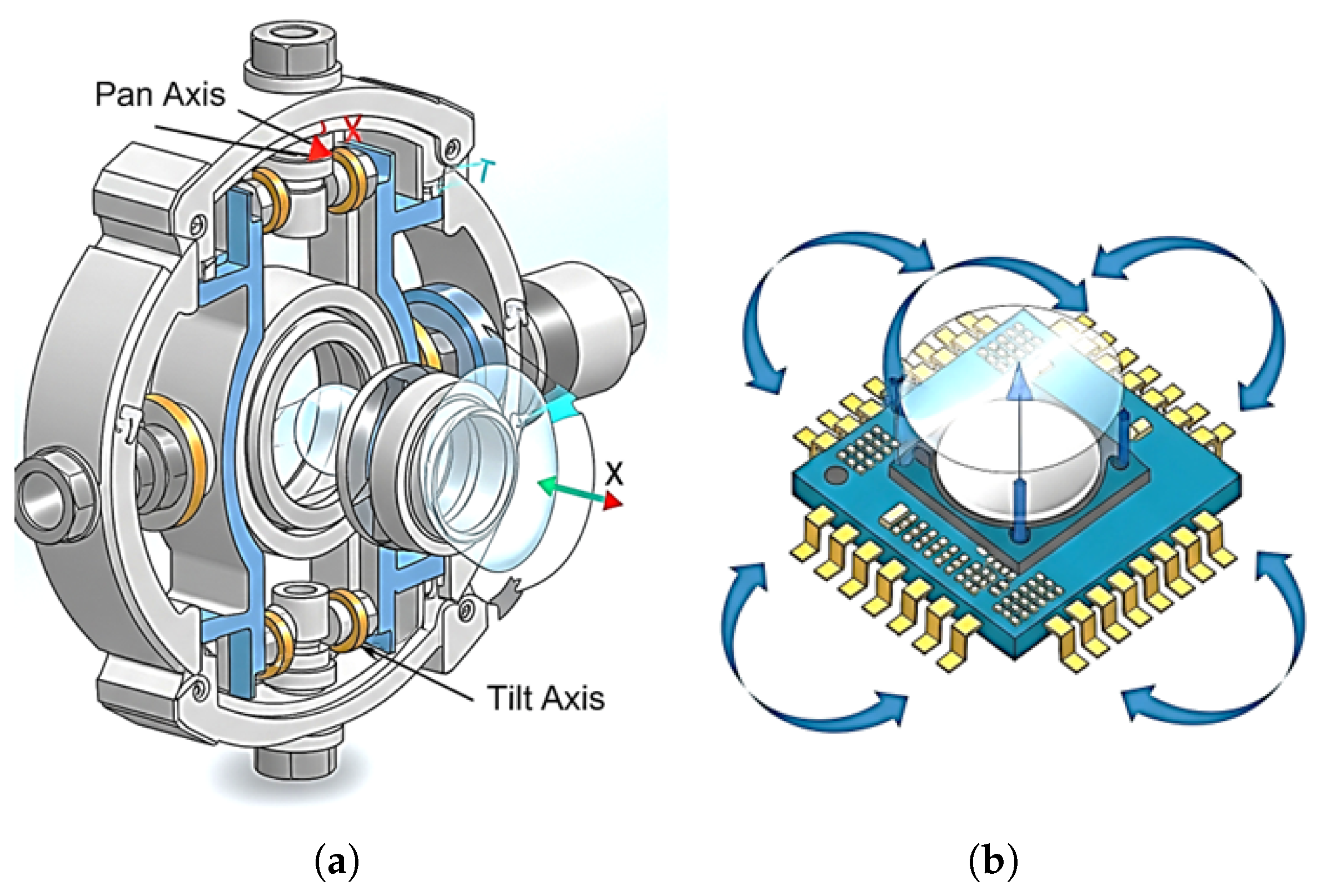
Figure 7.
Block diagram of closed-loop fine pointing mechanism.
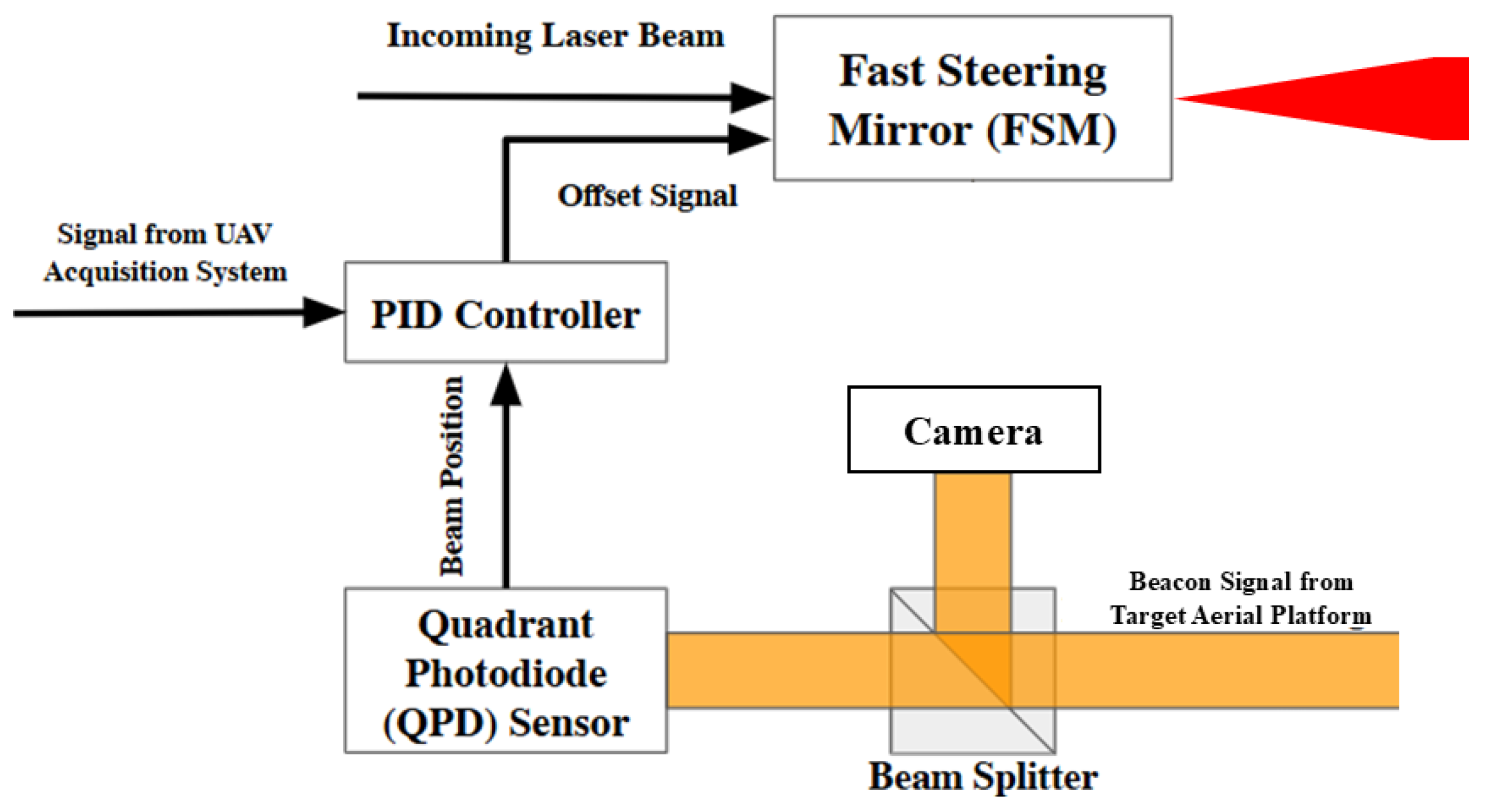
Figure 9.
Cascaded PID control loop block diagram.
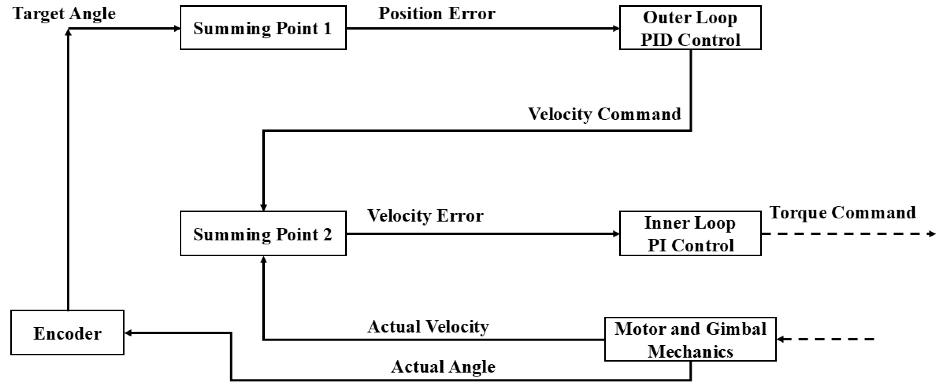
Figure 10.
Hybrid RF-FSO acquisition process.
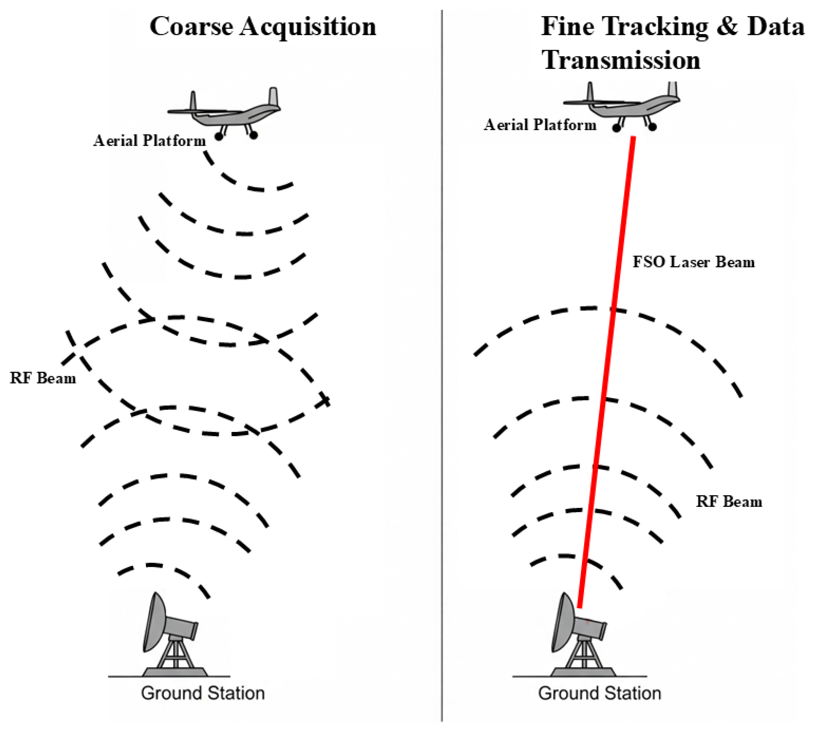
Table 1.
Comparative summary table.
| References | Platform Type | Gimbal Configuration | Tracking Aid | Performance Highlights | Notes |
|---|---|---|---|---|---|
| [9] | Small fixed-wing UAV | Two-axis with beacon | Beacon + servo | Tracked at 270 km/h | Real flight trials |
| [10] | Balloon/HAP | 2-axis coarse stage | GPS, beacon | Successful stratospheric FSO downlinks >1 Gbps | Classic early stratospheric optical trials |
| [11] | Small VTOL UAV | Two-axis AZ-EL gimbal | QPD + beacon | Fast auto-alignment, reduced acquisition time | DASC conference prototype |
| [12] | Small UAV | Two-axis servomotor | DGPS/ IMU | , Sub-degree error | Proof-of- concept air-to- ground link |
| [13] | UAV terminal/ ground | Two-axis gimbal + FSM | GPS/ beacon | Moderate speed, Coarse stage only | Light weight terminal, ground side |
| [14] | Stratos pheric UAV | Two-axis gimbal | Beacon + IMU | Sub-mrad stabilization in turbulent environment | Airborne study |
| [15] | CubeSat (1.5U) | Miniature 2-axis stage | Star tracker + reaction wheel | Early CubeSat laser downlink demo | First compact spaceborne laser terminal |
| [17] | Rotor- hover UAV | N/A (Receiver side APT) | 4-QD detector array | Analytical jitter model, optimized tracking | Four- quadrant array modeling |
| [18] | Multi-rotor UAV | N/A (receiver APT from [20]) | 4-QD array | Monte-Carlo validated pointing model | Modeled detector sizing |
| [19] | Multi-rotor UAV | Two-axis LiDAR- aided | LiDAR detection | Compact, low inertia, Robust under UAV motion | Coarse pointing |
| [20] | Hovering UAV relay | N/A (System- level model) | GPS, FSO path integration | Closed-form outage and capacity results | Relay optimi zation design |
| [21] | Multi-rotor with gimbal pod | 3D-printed 2-axis gimbal | Vision- IMU fusion | Particle filter minimized drift in natural conditions | Light weight vision- based stabili zation |
| [22] | Multi-rotor UAV | analytical model | Statistical | Az accuracy , El | Channel modeling including pointing error |
| [23] | Fixed- wing UAV +RIS | N/A (analytical + optimi zation) | RIS aided beam alignment | PSO + PPO minimize joint pointing and atmospheric loss | Trajectory optimi zation |
| [24] | CubeSat (3U) | Body-pointed | GPS + Mini star tracker | Successful LEO-to-ground lasercom without gimbals | Minimal APT, very low SWaP |
| [25] | CubeSat (6U) | Body-pointed | Star Tracker, GPS | >200 Gbps optical downlink; Tb-class per pass | Demonstrated record CubeSat optical communication throughput |
| [26] | Fixed- wing UAV | modeled trajectory | GPS + INS + control | 3D jitter-aware | Outlook to 6G UAV FSO networks |
Table 4.
Difference between mechanically decoupled and nested gimbals.
| Feature | Mechanically Decoupled | Nested Gimbal |
|---|---|---|
| Axis Interference | Minimal | High |
| Size | Large | Compact |
| Complexity of Control | Simple | Complex (due to coupling) |
| Cable Routing | Complicated | Easy |
| Scalability | High | Limited by nesting constraints |
| Suitability for UAV | Low to Medium | High |
| Rotation Range | Wide (independent) | Limited by internal structure |
Table 5.
Actuation technologies.
| Actuation Type | Principle | Use Case | Pros | Cons | Applications |
|---|---|---|---|---|---|
| Brushed DC Motors | Electro-mechanical torque via brushes | Legacy or cost-sensitive | Simple, low cost | Wear and tear, “EMI”, less precise | Low-Cost UAV gimbals, legacy payloads |
| Brushless DC Motors (BLDC) | Electronic commutation, magnetic torque | UAV gimbals, fine pointing | Compact, efficient, long life | Requires ESC/FOC drivers | UAV lasercom terminals, small satellite gimbals |
| Stepper Motors | Electromagnetic discrete steps | Coarse pointing systems | Open-loop control possible, precise steps | Can miss steps under high load | Coarse alignment in satellite optical terminals |
| Voice Coil Actuators | Linear magnetic field interaction | Fast stabilization (fine) | Fast response, frictionless | Small travel range, needs feedback | Fine beam steering for FSO ATP subsystems |
| Piezo- electric Actuators | Crystal deformation via voltage | Sub-microradian fine tracking | Ultra-precision | very small range, expensive | Fine beam steering mirrors in optical communication |
| Harmonic Drive (w/Servo Motor) | Flex-spline torque gear system | Nested gimbal needing precision | Zero backlash, high torque density | complex control, cost | High-precision satellite gimbals for GEO/LEO optical links |
| Magnetic Torquers | Magnetic interaction with Earth’s field | Space-based altitude control | No moving parts | Very low torque, slow | Satellite coarse atitude control before gimbal pointing |
| Reaction Wheels | Conservation of angular momentum | Satellite gimbal platforms | Precise torque control | Large, slow, high power consumption | Satellite fine pointing and stabilization for optical links |
| Gyroscopes (Control Moment Gyros-CMG) | Rotating mass generating torque | Spacecraft fine attitude control | High torque, precise attitude control | Complex, heavy, high power demand | High-capacity satellites needing agile optical beam poiniting |
| MEMS Actuators (Micro-mirrors, scanners) | Electrostatic/thermal deformation at micro-scale | Beam steering, fine pointing | Compact, low power, high speed | Limited angular range, fragile | CubeSat FSO PAT systems, miniature terminals |
| Shape Memory Alloys (SMA) | Phase change deformation via heating | Deployable or low-power actuation | Simple, lightweight, low power | Slow response, hyteresis | CubeSat deployable optics, secondary pointing |
| Electrostatic Actuators | Coulomb force-based actuation | MEMS-level fine actuation | Ultra-low power, fast response | Tiny forces, limited travel | MEMS micomirrors for optical communication beam steering |
| Magnetostrictive Actuators | Strain from magnetic domain alignment | Ultra-fine motion systems | Precise, high bandwidth | Expensive, limited adoption | Niche optical ATP systems requiring ultra-stability |
Table 7.
Recent research on mitigation strategies
| References | Problem Addressed | Solution Approach |
|---|---|---|
| [67] | Friction, resonance, sensor imperfection | Simulation of drive systems, lower cost gyro advantages |
| [68] | Vibration isolation at | Active inertial dampers + passive damping + notch filters |
| [69] | Heavy vibration impact | Two-stage vibration isolation design validated with flight tests |
| [70] | Wind gust-induced path deviation | Nonlinear guidance law with online wind estimate |
| [71] | Multirotor disturbance rejection | PID/MPC +EKF/UKF disturbance estimator comparison |
| [26] | Dynamic motion induced pointing error | 3D jitter model and trajectory optimization |
| [72] | Combined turbulence + pointing error | Statistical closed-form channel models |
Disclaimer/Publisher’s Note: The statements, opinions and data contained in all publications are solely those of the individual author(s) and contributor(s) and not of MDPI and/or the editor(s). MDPI and/or the editor(s) disclaim responsibility for any injury to people or property resulting from any ideas, methods, instructions or products referred to in the content. |
© 2025 by the authors. Licensee MDPI, Basel, Switzerland. This article is an open access article distributed under the terms and conditions of the Creative Commons Attribution (CC BY) license (http://creativecommons.org/licenses/by/4.0/).
Copyright: This open access article is published under a Creative Commons CC BY 4.0 license, which permit the free download, distribution, and reuse, provided that the author and preprint are cited in any reuse.


