Submitted:
01 September 2025
Posted:
02 September 2025
You are already at the latest version
Abstract
In the study, the behavior of the spherical bearing component of the L-100 bridge part (AlfaTech LLC, Perm, Russia) is considered within the framework of a finite element model. The influence of the pattern of the coupling of the antifriction layer with the lower steel plate on the operation of the part is examined: ideal contact, full adhesion, frictional contact. The thickness of the antifriction layer varied from 4 to 12 mm. The dependencies of the contact parameters and the stress-strain state on the thickness were determined. Structurally modified polytetrafluoroethylene (PTFE) without AR-200 fillers was considered as the material of the sliding layer. The gradual refinement of the behavior model of the antifriction material to account for structural and relaxation transitions was carried out on the basis of a wide range of experimental studies. In the first approximation, a model of the deformation theory of plasticity with linear elastic volumetric compressibility was identified. As a second approximation, a viscoelasticity model for the Maxwell body was constructed using Prony series. It was established that the viscoelastic model of the material allows for obtaining data on the behavior of the part with an error of no more than 15%. The numerical analog of the construction in an axisymmetric formulation can be used for predictive analysis of the behavior of the bearing, including when changing the geometric configuration.
Keywords:
bridge bearing
; geometric configuration
; polymer
; antifriction sliding interlayer
; FEM
; elastic-plastic
; viscoelasticity
; Prony
; contact interaction
1. Introduction
The design and construction of bridges is quite a complex process. This is due to a variety of social, economic, resource, technical and geographical factors [1,2,3]. The construction of structures in hard-to-reach areas, such as the Arctic territories, mountain gorges, and coastal areas, requires the adaptation of important structural components to extreme conditions. The use of modern materials and the adoption of new design and technological solutions to ensure long-term trouble-free operation of the structure is also important [1,4]. Every detail of the bridge structure is an important component that affects durability and safety. The bearing is one of the key elements. The bearings redistribute the load from the span structures, bear dynamic impacts from vehicles and impacts associated with various natural and climatic phenomena [4,5,6]. High demands on critical nodes prompt more detailed comprehensive engineering and technical research. The preliminary analysis includes an assessment of materials and existing design solutions [7,8,9]. The final analysis includes technical diagnostics and monitoring of the structure and its supporting elements [10,11].
There are many structural types of bridge bearings. But spherical bearings have become widespread due to their high reliability and durability [12,13]. Due to the construction of structures in difficult geographical and climatic conditions, extreme weather events, and critical temperature fluctuations, it is necessary to take into account various factors that affect the stability, strength, and durability of the structure [14,15]. For example, in [16], scientists assessed the impact of spherical steel bearings on train safety in conditions of seismic activity. In [17], studies were conducted of the wind load on a long-span bridge during typhoons in order to further accurately assess fatigue damage to structural components. New innovative shapes of spherical bearings are also being created, which can improve their bearing capacity and increase fatigue strength [18,19,20].
Equally important are the issues of materials from which the main parts of the spherical bearing are made. The main influence on the work of the part is exerted by the material of the antifriction layers. Scientists have made a great contribution to the development of materials in terms of modifying compositions and improving their tribological characteristics [21,22,23]. Currently, there is a large selection of modern polymers and composites that can be used as a sliding layer of the bearing [24,25,26]. These include polytetrafluoroethylene (PTFE), polyetheresterketone (PEEK), polymethylmethacrylate (PMMA), polyurethane (PU), polyamide (PA), ultra-high-molecular-weight polyethylene (UHMWPE) and composites based on them, antifriction composite materials based on fluoroplast-4 with various nanofillers, and modified fluoroplast [27]. In [28], an attempt was first presented to replace PTFE with ceramics as a friction material by conducting a preliminary friction test. Subsequent studies [29,30] demonstrated excellent wear resistance and durability of the specified material even under high loads. However, the analysis of the behavior of materials requires the construction of numerical models. The digital model of the material should describe the physico-mechanical and thermomechanical properties close enough to the experimental results. This leads to the need for a large number of empirical studies, as well as the use of mathematical tools to describe models.
The geometric parameters of the interlayer and its interaction with other structural elements also influence the deformation behavior of the bearing [31,32]. For example, in [28] the authors showed that improved interlayer shapes with convex and rounded edges with an increase in vertical load provide a slight increase in stresses and deformations compared to its canonical shape. The texturing of work surfaces also affects the effective coupling of elements: it can reduce friction, increase wear resistance and increase the service life of components [33,34,35]. The study of structural features is important for understanding the behavior of the structure, as well as for optimizing it to meet the required operating conditions.
Of particular interest is the mathematical description of the behavior of antifriction materials. The main research areas are: rheology [36], viscoelasticity [37,38], viscoplasticity [39], viscoelastic-plasticity [40,41,42], phase transitions, [43,44] etc. It is important to note the complex nonlinear behavior of modern antifriction materials, which is confirmed by numerous field experiments [45,46,47]. Experimental studies combined with numerical modeling make it possible to study in more detail the behavior of materials, the processes occurring in the constituent elements of structures, and to evaluate the stress-strain state of parts and assemblies depending on the main characteristics and parameters. The use of numerical methods reduces the cost of experimental research and provides an opportunity for a deeper analysis of the functioning of the structure and consideration of a large number of options for its implementation. The selection of the sliding layer material, together with structural changes, can contribute to the rational operation of the elements of the spherical bearing of the bridges. Numerical modeling makes it possible to predict the deformation behavior of the structure within the framework of complex temperature and force effects, including taking into account the contact interaction of the elements [48,49,50]. It is important to create digital models of the design, taking into account the nonlinear behavior of the materials of the antifriction layers.
The finite element model of the spherical bearing L-100 (AlfaTech LLC, Perm, Russia) was built as part of the current study. The analysis of the influence of the elements coupling pattern on the parameters of the unit contact interaction, including depending on the thickness of the sliding layer, was performed using it. A gradual refinement of the behavior model of the antifriction interlayer material has been performed. Widely used models were considered: both elastic-plastic and viscoelastic. A high-quality digital analog of the material is necessary to form a model of the spherical bearing that is closest to the actual structure. A multifactorial analysis of the structure's behavior was performed as part of the work. Analyzing the pattern of the coupling of the antifriction layer with the lower steel plate and the thickness of the polymer material on the behavior of the structure allows us to obtain data relevant to designers when developing bearings for specific operating conditions and structures.
2. Materials and Methods
2.1. The Design of the Spherical Bearing
The influence of the thickness of the polymer antifriction protective sliding layer and its pattern of coupling with the lower steel plate of the spherical bearing of the bridge span is considered in the framework of the study. The geometry of the contact node of the spherical bearing includes an upper (1) and lower (2) steel plate interacting through a spherical sliding layer of antifriction material (3) (Figure 2).
The geometric configuration corresponds to the bearing L-100 (AlfaTech LLC, Perm, Russia). The maximum height of the structure mm consists of the thickness of the upper steel plate with a polished spherical segment mm, the height of the lower steel plate with a spherical cutout mm, and the thickness of the sliding layer mm. The standard interlayer thickness is mm. The effect of increasing the thickness of the sliding layer to 6, 8, 10 and 12 mm on the work of the structure will be considered as part of the study. The antifriction layer end face (3) is partially in contact with the steel structural elements. 2 mm of the sliding layer is free from contact with the lower oil plate (protrusion of the antifriction layer) to eliminate the possibility of metal-to-metal contact during construction. The polymer interlayer is pressed into the bottom steel plate. The standard inclination angle of the antifriction layer end face is °. The width is mm. The nominal vertical load is 1000 kN.
Within the framework of the calculation scheme, a simplified geometry of the sliding layer is considered without taking into account the depressions for the lubricant. The problem is considered in an axisymmetric formulation using the finite element method in the software ANSYS Mechanical APDL 2021R2 (Livermore, CA, USA).
On the contact surface a frictional contact is implemented with a previously unknown pattern of the distribution of contact status states:
– sliding
when ;
– no contact
– full attachment (adhesion)
where is the coefficient of friction, is the designation of the axis that lies in the plane tangent to the contact surface, is movement along the normal to the corresponding contact boundary, is movement in the tangent plane, is stress along the normal to the contact boundary, are tangential stresses at the contact boundary, and 1-2 are conditional numbers of interface surfaces that belong to different bodies.
The friction contact corresponds to the polished surface of the steel in the interface area.
On the contact surfaces , three conjugation patterns are implemented:
1. An ideal contact, created by modeling a finite element node-to-node grid, which makes it possible to obtain uniform fields of displacements, stresses and deformations at the interface:
2. Full adhesion, which corresponds to the processing of the conjugation surface of the “torn thread” type (3).
3. Frictional contact (1)-(3), which includes different statuses with a previously unknown nature of their distribution over the surface: full adhesion, slidiing and no contact.
For a spherical sliding surface in the interface area of the upper balancer and the antifriction layer, minimal roughness is required. This allows one to achieve a polished surface of the spherical segment of the balancer. The bed of the balancer (spherical cutout of the lower steel plate) can be processed in different ways to ensure a different pattern of the coupling of the elements: without additional processing, a rough surface of the “torn thread” type to ensure maximum adhesion, or a polished surface. The pattern of the treatment can have a strong influence on the contact parameters and the stress-strain state of the structure. In this paper, the pattern influence of the sliding antifriction layer coupling with the balancer bed on the operation of the bridge bearing is considered.
2.2. Sliding Layer Material
Structurally modified polytetrafluoroethylene (PTFE) without fillers AR-200 (Scientific and Production Enterprise Arflon LLC, Moscow, Russia) is considered as the sliding layer material. The material is obtained by compaction and high-temperature physico-chemical modification. The material has a spherulite packaging of macromolecules, the color is white. The AR-200 is used to manufacture sliding parts.
Initially, to build a model of the materials behavior, a series of experiments were carried out implementing a homogeneous deformed state of cylindrical samples of 20×20 mm using a Zwick Z100SN5A material testing machine (Zwick Roell AG, Ulm, Germany) and a Multisens extensometer (Zwick Roell AG, Ulm, Germany). Experimental studies were conducted at the Ural Branch of the Russian Academy of Sciences (ICMM UB RAS, Perm, Russia). The staging and conducting of the experiments was supervised by Dr. A.A. Adamov. The maximum deformation level of the sample of 10% was selected from the assessment of the maximum deformations of the bearing sliding antifriction layer and as the maximum permissible level for using the small deformations theory. A multi-stage testing program was implemented up to a maximum strain level of 10% with relaxation, unloading and recovery areas. The traverse movement speed was 3 mm/min. Experimental studies were conducted at room temperature.
The experiment and the processed results of empirical studies are shown in Figure 3.
It is established that the material is a viscoplastic compressible body with nonlinear viscoplastic volumetric compressibility and phase transitions induced by the stress state.
In the first approximation, a model of the deformation theory of plasticity with linear elastic volumetric compressibility has been identified (Figure 4, a). The model was built for the case of active loading and does not take unloading into account.
In the second approximation, a viscoelasticity model for the Maxwell body was constructed using Prony series (Figure 4, b). The mathematical model was previously described in [51] and is based on the results of a series of experimental studies on uniaxial stress state (USS).
Within the viscoelastic description of the material behavior model, the dependence of weighting coefficients on relaxation times for 34 terms of the Prony series was selected, along with the empirical constants of the Williams–Landel–Ferry (WLF) temperature-time superposition and , as well as the constant base temperature °K. The model parameters correspond to room temperature. Limited experimental data has been established to describe the behavior of the AR-200 in a wide range of temperatures and deformation rates within the framework of the thermomechanics of materials.
To refine the viscoelastic behavior model of the material, a series of empirical studies were conducted on three-point bending of rectangular specimens with average dimensions of mm using a dynamic mechanical analyzer DMA Q800 (TA Instruments, New Castle, USA) over a wide temperature range of [−40; +80] ℃ (Figure 5). The research was conducted at the plastics laboratory of Perm National Research Polytechnic University (Perm, Russia).
The dependencies of the storage modulus, loss modulus, and loss angle tangent on temperature (Figure 6), as well as the glass transition temperature of the AR-200 antifriction material, 8 °C. The material has a clear peak in the tangent of the loss angle, which corresponds to materials exhibiting a transition region from a glassy to an elastic state near the glass transition temperature.
The storage modulus reflects structural changes in the material. With increasing temperature, a decrease in the storage modulus is observed, which is associated with the softening of the material and a reduction in the elastic modulus. The change in the loss modulus is related to relaxation transitions in the materials. In the region of increasing loss modulus, the material is in a glassy state; with further temperature increase, the loss modulus decreases, and the materials transition to a highly elastic state.
The results of the DMA experiments formed the basis for a refined model of the behavior of the AR-200 material within the framework of the theory of viscoelasticity using the temperature-time analogy WLF (Figure 7).
The long-term modulus of elasticity at the initial and final moments in time and has been determined. The constant reference temperature , and the empirical constants of the temperature-time superposition (WLF) and have been refined, taking into account a wide temperature range of [−40; +80] ℃. For the description of the viscoelastic behavior model of materials, 40 pairs of coefficients , have been defined.
For all AR-200 models, the Poisson's ratio was determined experimentally and is equal to 0.461.
Experimental studies included at least three repetitions to ensure the statistical significance of the results.
2.3. The Numerical Model
The numerical implementation of the problem was carried out in the ANSYS Mechanical APDL 2021R2 software package using PLANE182 type axisymmetric quadrilateral elements with Lagrangian approximation. Surface-to-surface contact interaction was implemented using the contact element pair CONTA171 and TARGE169. The primary procedures for constructing finite element analogs are based on the Galerkin method with the selection of basic functions having compact support according to the finite element method. A step-by-step loading algorithm is used with iterative refinement of the distribution of contact zones, penetration values and contact forces. The iterative procedure is performed until the results of two consecutive iterations give the values of the contact forces and the amount of penetration within the specified accuracy.
Frictional contact is based on the basic Coulomb friction model, taking into account the conditions of critical tangential stress in the contact zone, which exceeds the yield strength in the material below the surface (the expansion model of classical Coulomb friction). The coefficient of friction is chosen to be a constant value of 0.04 and corresponds to the manufacturer's data of the bridge support parts for the steel-polymer contact pair.
To describe the elastic-plastic behavior of the sliding layer material, the MISO model was used; for the viscoelastic behavior, the Prony series was employed. The steel structural elements were modeled in the framework of the theory of elasticity with an elastic modulus of 2e11 and a Poisson's ratio of 0.3.
Previously, the convergence of the numerical solution of the problem on the degree of discretization of the system was investigated [53]. It was found that with a standard thickness of 4 mm of the sliding layer, 16 elements are required for the thickness of the interlayer. The overall dimensions of the final elements of the steel plates in the contact area correspond to the finite element division of the sliding layer, with the size of the elements increasing gradiently as they moved away from the contact area. Finite element models with a sliding layer thickness of 4 and 12 mm are characterized by approximately 50 and 63 thousand nodal unknowns, respectively.
3. Results
3.1. Analysis of the Effect of the Interface Pattern of the Sliding Layer with the Lower Steel Plate at a Interlayer Standard Thickness
At the first stage of the study, an assessment was made of the effect of the interface pattern of the sliding layer with the lower steel plate at a standard thickness of the antifriction layer. The behavior of the sliding layer material is modeled within the framework of the elastic-plastic formulation.
Of the greatest interest are the levels and patterns of distribution of contact parameters on the sliding surface of the spherical balancer , as well as the deformation of the sliding layer near the protrusion of the antifriction layer.
The pattern of the distribution of contact pressure and contact tangential stress on , obtained by modeling different types of conjugation on , is shown in Figure 8.
With all types of coupling the contact surfaces do not diverge, i.e. the contact status “no contact” did not manifest itself during the deformation of the structure. The pattern of the interface of the lower steel plate with the interlayer has the maximum effect on the distribution of zones with different contact statuses . With ideal contact and full adhesion, the zone of change of contact states from full adhesion to sliding shifts closer to the edge of the sliding layer. The full adhesion area is 30.97% of the initial contact area with ideal contact and full adhesion , and 16.48% of the initial contact area with frictional contact . For the frictional contact , the total adhesion area comprises 24.09% of the initial contact area. The maximum level of contact pressure on the surfaces and is the same for all types of coupling of the antifriction layer with the lower steel plate. The maximum level of and at frictional contact is 7-9% higher than at ideal contact and full adhesion. This effect is associated with a decrease in the area of full adhesion at the interface with the spherical balancer (the area of adhesion is almost 2 times smaller). The maximum levels of and at full adhesion are lower than at ideal contact by 1.41 and 0.84%, respectively.
Plastic flow of the material is observed near the protrusion of the antifriction layer. Since the elastic-plastic model does not take into account material relaxation, the deformation of the sliding layer is overestimated relative to the actual structure. The influence of the pattern of the connection on the displacements normal to the end face of the polymer sliding layer of the support part is shown in Figure 9.
The maximum displacement of the sliding layer is observed near the sliding surface . The layer is subject to deformation under the standard load during indentation with a spherical balancer. Near the protrusion zone of the antifriction layer, the material is in a state of plastic flow. The deformation of the layer can be refined by introducing viscosity into the material behavior model. During friction contact, the sliding layer material can slip relative to the lower table plate, resulting in a 49.8% increase in the maximum normal displacement level. The differences in case of ideal contact and full adhesion do not exceed 0.1%. The pattern of the distribution of displacements along the normal to the surface of the sliding layer end exhibits minor differences.
For better clarity, consider the differences in the average values , , and (Figure 10). , , and are the mean arithmetic errors of the parameters across the surface. Parameters obtained during ideal contact were selected as the reference values: The model has only one contact surface and requires less computational power to assess changes in the geometry of the structure during engineering surveys.
The maximum differences between solutions with the modeling of a contact pair of elements for different types of contact are observed in the normal movement of the end face. The difference between frictional contact and ideal contact is about 50%, and the full adhesion is no more than 7.5%. The minimal differences between the solutions are, as expected, in the contact pressure, which is least sensitive to different parameters of the numerical implementation. At the same time, the difference between frictional contact and ideal contact is more than 6.5%. Contact pressure is more sensitive to contact settings: the difference between full adhesion and ideal contact is 5.64%, while for frictional contact it is 23.47%.
Figure 11 shows the isofields of the stress-strain state parameters (intensity of stresses and deformations) of the sliding layer of the bearing with different contact patterns .
The maximum intensity levels of stresses and deformations are observed near the edge of the sliding layer in the protrusion area. The maximum strain level exceeds 10%, while the stress level corresponds to the maximum stress level of the material deformation curve due to the limitations of the model. The maximum area is observed during frictional contact. . This is due to the fact that the material of the sliding layer in this formulation of the problem has a large deformation due to the possibility of slipping on the contact surfaces. The maximum intensity of deformations is observed near the collar of the spherical cutout of the lower steel plate, as a concentrator appears there. To clarify the level and pattern of the distribution of stress-strain state parameters, it is necessary to clarify the model of behavior of materials, taking into account relaxation. The implementation of full adhesion makes it possible to refine the field of distribution of stress-strain state parameters, since a single field of stresses and deformations is not formed on the interface surfaces of the antifriction interlayer and the bottom plate. With full adhesion , a minimum level is observed, which demonstrates the effectiveness of processing the contact surfaces of the lower steel plate according to the “torn thread” type.
If it is necessary to save computing resources, the “torn thread” surface interaction can be modeled as an ideal contact. The differences in the numerical solution of the problem with the standard thickness of the sliding layer do not exceed 10%.
3.2. Analysis of the Effect of the Thickness of the Bearing Sliding Layer on the Structure Behavior
At the second stage of the study, an assessment was made of the effect of the thickness of the sliding layer at a constant protrusion of the antifriction layer and the different coupling pattern of the elements.
The pattern of the distribution of contact parameters and the stress-strain state of the structure does not differ with the different pattern of the interface of the sliding layer with the lower steel plate. Data on the effect of the thickness of the antifriction interlayer on the behavior of the structure is shown on the example of a model with an ideal steel-polymer contact in the interface zone of the sliding layer with the lower steel plate.
Next, the effect of the thickness of the interlayer on the maximum parameter levels with different coupling patterns is considered.
3.2.1. Ideal Contact Along the Interface Surfaces of the Sliding Layer with the Lower Steel Plate
The distribution of contact parameters on at different is shown in Figure 12.
The pattern of the distribution of contact pressure and tangential contact stress has small differences when the thickness of the sliding layer changes. As the thickness of the sliding layer increases, there is a tendency to 0 contact parameter values near the edge of the interlayer. This effect is associated with the deformation of the sliding layer material and an increase in the volume of the material in which plastic properties are manifested. With an increase in the thickness of the interlayer > 12 mm or a change in the deformation conditions, a contact area with the status of complete detachment may occur. At ideal contact , the maximum level of contact parameters changes slightly: an increase in the thickness of the sliding layer up to 8 mm by a maximum of 1.2%, followed by a decrease. The maximum value of the tangential contact stress is observed in the zone where the contact status changes from sticking to sliding. It can be noted that there is a tendency to decrease the percentage of the contact area that is in a state of full adhesion. At the same time, the larger the contact area is in the state of adhesion, the larger the volume of the material works within the framework of hydrostatic compression and exhibits only elastic properties.
The distributions of the normal end face movements are shown in Figure 13.
An increase in the thickness of the sliding layer leads to an increase in the maximum level of displacement normal to the surface of the protrusion of the antifriction layer. With a thickness of 12 mm, the maximum level of displacement along the normal of the end face increased by more than 2.5 times. The thickness of the interlayer is regulated by regulatory documents of the Federal Road Agency “Rosavtodor” (Moscow, Russia). It is necessary to consider the effect of the thickness of the interlayer on all sizes of spherical bearings, with different configurations. The structures have different radii of curvature of the spherical segment, which was previously considered in [53]. There are also different approaches to determining the size of the protrusion of the antifriction material. One of the areas of research may be a comprehensive assessment of the influence of the projection geometry on the behavior of the structure. To clarify the pattern of the deformation of the end face of the sliding layer, it is necessary to take into account the relaxation of the antifriction material. This was carried out in further research.
3.2.2. Comparative Analysis of the Structure Behavior at Different Thicknesses and Sliding Layer Interfaces
The next stage of the work was the analysis of the influence of the coupling pattern of the lower steel plate with the antifriction sliding layer for all variants of the geometric configuration of the bearing.
Figure 14 shows the dependencies of the maximum level of contact pressure , tangential contact stress and normal displacements , as well as the percentage of the surface area in the state of full adhesion on the thickness of the sliding layer with different interface patterns .
It can be noted that the deformation of the spherical bearing at ideal contact and full adhesion has small differences: The field of stress and strain distribution is specified, especially near the antifriction sliding layer, as well as contact parameters. At the same time, to increase the speed of evaluating the deformation behavior of the structure during engineering surveys, a model with a single contact surface and ideal interface can be used.
The level of contact parameters at ideal contact and full adhesion is lower than that of a frictional contact with a sliding layer thickness of up to 10 mm. As the thickness of the sliding layer increases, the differences in the parameters of the contact stress-strain state of the spherical bearing with a different type of interface (surface treatment) with the lower steel plate decrease. With thicknesses of more than 10 mm, the differences are less than 2%.
The percentage of the surface area in the state of full adhesion decreases with increasing thickness of the interlayer. An increase in the area of material slippage leads to a significant increase in displacements along the normal of the end of the sliding layer in the area of the protrusion of the antifriction layer. At the same time, the “no contact” status of the interface surfaces is not observed on for all contact options .
3.3.. Influence Analysis of the Behavior Model of the Sliding Interlayer Material
To form a model of the spherical bearing that is closest to the actual structure, it is necessary to evaluate the influence of the behavior patterns of the sliding layer material on the results of structural deformation. The evaluation of the model was performed with a sliding layer thickness of 4 mm.
As part of the work, a gradual refinement of the material behavior model was performed to account for structural and relaxation transitions. This is necessary to move on to dynamic tasks, including at a wide range of temperatures, to assess the life of the structure and its operation under cyclic and seismic influences.
Three models of behavior are considered:
- The elastic-plastic model of the material behavior is based on experimental data on the free compression of cylindrical samples. The model is implemented only for the case of active loading.
- The viscoelasticity (USS) model is based on data from multi-stage tests for free compression of cylindrical samples to a maximum strain level of 10% with relaxation, unloading and recovery areas. The model is limited within the range of temperatures close to room temperatures of 22-23 ° C. It does not take into account the plasticity of the material and a number of phenomena and effects of the viscoelastic pattern of the material.
- The viscoelasticity (DMA) model is based on the entire set of experimental data, taking into account the DMA study of material behavior over a wide temperature range. The model does not take into account the plasticity of the material.
Figure 15 shows a comparative analysis of the three models of antifriction material behavior within the parameters of the stress-strain state of the elements of the spherical bearing with a standard sliding layer thickness of 4 mm.
The elastic-plastic behavior model of the material in the sliding layer has a significant limitation associated with an asymptotic stress level when the deformation level exceeds 10%. Additionally, the model does not account for material relaxation, which can be observed even with iterative loading application. This results in overestimated deformation characteristics at significantly underestimated stress levels. The modeling error of the deformation of the spherical bearing compared to the data from field tests is from 57.7 to 71.9%. The maximum error is observed during frictional contact .
The Viscoelasticity (USS) model makes it possible to refine data on the behavior of the sliding layer material. This leads to a significant reduction in the deformation of the antifriction layer, while clarifying the level of stresses and deformations of the material. The model makes it possible to effectivly describe the multi-stage cyclic deformation of samples [52]. The error in modeling the deformation of the spherical bearing from the field test data is from 44.1 to 57.4%. There is an overestimation of the numerical experiment data from the field. The maximum error is observed at full adhesion .
The Viscoelasticity (DMA) model allows us to obtain a numerical analogue of the spherical bearing, as close as possible to the real design. The error of modeling the deformation of the spherical bearing from the data of field tests is from 13.8 to 21.1 %. The minimum error is observed with full adhesion .
The results of field tests on the draft of the bearing contained multi-stage loading with load holding. These effects are not taken into account in the current model of deformation of the bearing. The pattern of the processing of the balancer bed is “torn thread”, which is confirmed by the minimum error of the model with full adhesion to the interface surfaces . The level of settlement of the spherical bearing model with a refined viscoelastic model of material behavior is as close as possible to the actual design. It should be noted that the model is implemented in an axisymmetric formulation and allows one to quickly evaluate engineering solutions for changing the geometric configuration of elements.
The behavior model of the sliding layer material can be refined after conducting a series of numerical experiments on the dependence of the coefficients of thermal expansion on temperature, as well as a series of experiments on uniaxial stress over a wide temperature range. It also requires consideration of the plasticity of the material, which can be done when switching to the Anand model.
Comparative Analysis of Viscoelastic and Elastic-Plastic Models of Material Behavior
We will perform a comparative analysis of the behavior of the bearing in the case of elastic-plastic and viscoelasticity (DMA) models of the behavior of the sliding layer material.
The pattern of the distribution of contact parameters when modeling the behavior of the sliding layer material within the framework of elastic-plastic and viscoelastic settings is shown in Figure 16.
The behavior model of the sliding layer material does not affect the pattern of the distribution of contact parameters. The Viscoelasticity (DMA) model of the sliding layer material shows a decrease in the level of contact parameters compared to elastic-plasticity by 6-8% with ideal contact and full adhesion , and by 13-15% with frictional contact. The percentage area of the contact surface in the state of full adhesion, is greater for the viscoelastic material behavior.
Figure 17 shows the movements along the normal of the end of the sliding layer when modeling the behavior of the sliding layer material in the framework of elastic-plastic and viscoelastic settings.
The maximum level of movement along the normal of the end of the sliding layer with viscoelastic behavior of the sliding layer material is 3-5 times lower than with elastic-plasticity.
Figure 18 shows the dependencies of the maximum level of contact pressure , tangential contact stress and normal displacements , as well as the percentage of the settlement of the bearing on the sliding layer thickness in the case of an elastic-plastic and viscoelastic behavior model of an antifriction material.
In the viscoelastic behavior model of an antifriction material, with an increase in the thickness of the sliding layer, a significant increase in the level of contact pressure and tangential contact stress is observed with ideal contact and full adhesion . These effects are associated with rather harsh deformation conditions of the structure with an increase in the volume of a more malleable material with the possibility of structural and relaxation transitions. With frictional contact, there is a decrease in contact pressure and a small change in the level of tangential contact stress. In general, the contact parameters of the spherical bearing with viscoelastic behavior of the sliding layer material are lower with a sliding layer thickness of less than 10 mm than with elasticoplastic behavior.
With the viscoelastic behavior of the sliding layer, the deformation of the antifriction material in particular and the spherical bearing as a whole is less than with the elastic-plastic behavior of the material.
The parameters of the contact stress-strain state of the bearing with a standard thickness of the sliding layer depend little of the coupling pattern of the antifriction layer with the lower steel plate.
Of interest is the change in the percentage of the contact surface area in the state of full adhesion, since in this case hydrostatic compression of the sliding layer is observed and the material operates within the framework of the theory of elasticity.
Figure 19 shows the dependencies of the percentage of surface area and (for the case of frictional contact along the interface surfaces of the sliding layer and the lower steel plate) in the state of full adhesion on the thickness of the sliding layer with elastic-plastic and viscoelastic models of antifriction material behavior.
The viscoelastic behavior of the material and its deformation affects the distribution of contact statuses on the sliding surface of the spherical balancer. The percentage of the surface area in the state of full adhesion is greater with viscoelastic behavior of the sliding layer material. As the thickness increases, the percentage of the surface area in the state of full adhesion decreases with all the considered models of the behavior of the sliding layer material.
It can be noted that with an increase in the thickness of the sliding layer with viscoelastic behavior of the antifriction material on the interface surface in the case of frictional contact, an increase in the percentage of the surface area in the state of full adhesion is observed. This means that with sufficiently large sliding layers, additional surface treatment of the interface of the lower steel plate with a “torn thread” interlayer is not required, thus reducing the time and economic costs of manufacturing the structure.
4. Discussion
Spherical bearings are a type of high-load multirotational bridge bearings (HLMR) and compensate for various types of loads from the bridge span and the environment. The effective operation of bearings is related to the gaps between the steel structural elements and the thickness of the sliding layer [54]. Increasing the thickness of the sliding layer can reduce the resistance to rotation, internal wear and damage, and can also increase the bearing capacity of the structure. However, the restrictions on the thickness of the sliding layer have not been determined so far. In the current study, the dependencies of the contact parameters and the stress-strain state of the spherical bearings on the thickness of the sliding layer have been determined. These studies were transferred to the manufacturers of bridge bearings and are taken into account in engineering methods for calculating the geometric configuration of the structure.
The results on the deformation of the bearing correlate with data from other studies and the results of field experiments [18,55]. The displacement level of the bearing at 1000 kN is in good agreement with the data of field experiments presented in [18]. The maximum stress level of a standard spherical bearing is also commensurate with the data obtained in our study. The pattern of the stress distribution in the sliding antifriction layer corresponds to the results obtained by Deng et. al. [55]. The maximum stresses of the sliding layer are also observed near the protrusion of the antifriction layer. This confirms the possibility of using models in the framework of simulation modeling for a multifactorial analysis of the behavior of structures in statics and dynamics.
Mechanical treatment of the sliding surface can ensure efficient and long-term operation of the bearing [54]. In this case, the influence of the pattern of the surface treatment of the lower steel plate in the area of contact with the antifriction layer can also affect the operation of the spherical bearing. As part of the study, it was found that by ensuring full adhesion at the interface, the interface of the sliding layer with the lower steel plate reduces the deformation of the protrusion of the polymer interlayer and the settlement of the structure. At the same time, studies of the behavior of bearings most often consider only one type of coupling of elements [55,56]. Studies often do not take into account the friction on the interface surfaces [55]. And modeling the behavior of the sliding layer material does not take into account the viscoelastic, creep, and plasticity of materials. However, in the framework of field tests, viscous deformation of the sliding layer and plastic flow of materials were observed [54,57]. Nonlinear effects in spherical hinges related to the behavior of materials and the contact state of the elements are complex phenomena and are an interesting area of research for understanding the work of the structure [58]. The influence of the coupling pattern of antifriction material and steel structural elements, including taking into account frictional properties, is necessary to evaluate the operation and rationalize the bearings [28]. The current work has analyzed, as a first approximation, the influence of the behavior model of the sliding layer material and the pattern of its interface with steel structural elements. A model of a spherical bearing with viscoelastic behavior of an antifriction material with full adhesion on the interface surfaces of the sliding layer with the lower steel plate allowed us to obtain a discrepancy with experimental data of less than 15%. Comparison with data from experimental studies by other authors shows an error of less than 10% in the model [18]. A large percentage of the difference between the settlement of the model and the experiment is due to the multi-stage experimental program, as well as the limitations of the geometric model of the bearing in the numerical implementation (grooves with lubricant are not taken into account).
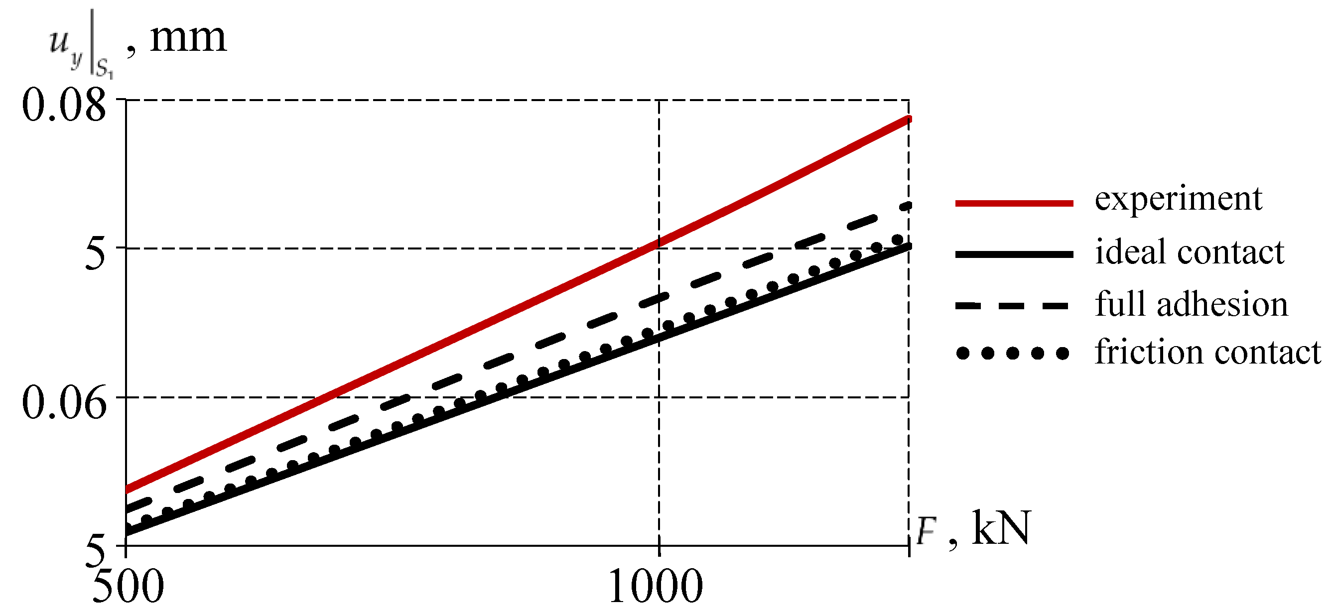
Let's consider the multi-stage loading of a model with exposure sections, according to a full-scale experiment (Figure 20).
The discrepancy between the results of the numerical simulation and the experiment does not exceed 20% for all variants of the interface of the sliding layer with the lower steel plate of the bearing. The maximum error is observed when modeling an ideal contact . The minimum error of numerical simulation at a nominal load of 1000 kN is observed at full adhesion (~ 11.37 %). The experiment involved bearings with the character of processing the metal surfaces of the interface of the lower steel plate according to the “torn thread” type, which allows for maximum adhesion to the sliding layer of the antifriction material.
5. Conclusions
As part of the first stage of the study, the influence of the coupling pattern on the deformation behavior of spherical bearings of a bridge structure at a standard thickness of the antifriction layer was analyzed. Three coupling options are considered: ideal contact, full adhesion, and frictional contact. The behavior of the sliding layer material was modeled within the framework of an elastic-plastic formulation. A number of patterns of deformation behavior of bridge bearings have been established:
1) The change in the coupling conditions has the greatest effect on the area of full adhesion . In the case of ideal contact and full adhesion the total adhesion area is 30.97% of the initial contact area, and in the case of frictional contact, it is 16.48% of the initial contact area.
2) The maximum differences between solutions with the modeling of a contact pair of elements for different types of contact are observed in the normal movement of the end face. The difference between frictional contact and ideal contact is about 50%, full adhesion is not more than 7.5%. Contact pressure: the difference between full adhesion and ideal contact is 5.64%, and frictional contact is 23.47%.
3) The effects of plastic flow of the material in the vicinity of the protrusion zone of the sliding layer were observed, which needs to be clarified within the framework of applying the viscoelastic behavior model in numerical implementation.
At the second stage of the study, an assessment was made of the effect of the thickness of the sliding layer at a constant protrusion of the antifriction layer and the different pattern of the coupling of the elements. The pattern of the distribution of contact pressure and tangential contact stress has small differences when the thickness of the sliding layer changes. However, an increase in the thickness of the sliding layer leads to an increase in the maximum level of movement normal to the surface of the protrusion of the antifriction layer, which is also confirmed by the results obtained when changing the pattern of the interface. This effect is associated with a decrease in the surface area in the state of full adhesion.
To form a model of the spherical bearing that is closest to the real structure, an assessment of the influence of the behavior patterns of the sliding layer material on the results of structural deformation was performed. The MISO model was used to describe the elastic–plastic behavior of the sliding layer material, and the Prony series was used for the viscoelastic behavior. The viscoelastic behavior of the material and its deformation affects the distribution of contact statuses on the sliding surface of the spherical balancer. The percentage of the surface area in the state of full adhesion is greater with viscoelastic behavior of the sliding layer material. As the thickness increases, the percentage of the surface area in the state of full adhesion decreases with all the considered models of the behavior of the sliding layer material. The viscoelastic behavior model of the antifriction material makes it possible to minimize the deviation of the numerical model of the bearing from the actual structure.
Several directions are being considered as further development of the work:
- consideration of the experimentally obtained friction properties of the steel-polymer pair in the analysis of the deformation behavior of the structure;
- analysis of the effects of cyclic and seismic loads, including temperature and time considerations;
- transition to a viscoelastic model of antifriction material behavior.
Author Contributions
Conceptualization, A.A.K., Yu.O.N., and A.P.B.; methodology, A.A.K.; software, A.A.K., Yu.O.N., Yu.S.K., and A.P.B.; validation, A.A.K.; writing—original draft preparation, A.A.K., Yu.S.K., and Yu.O.N.; writing—review and editing, Yu.S.K., and A.P.B.; visualization, A.A.K., Yu.S.K., Yu.O.N., and A.P.B.; funding acquisition, Yu.O.N. All authors have read and agreed to the published version of the manuscript.
Funding
The study was supported by the Russian Science Foundation grant No. 25-29-00470, https://rscf.ru/project/25-29-00470/.
Institutional Review Board Statement
Not applicable.
Informed Consent Statement
Not applicable.
Data Availability Statement
The original contributions presented in this study are included in the article. Further inquiries can be directed to the corresponding author.
Conflicts of Interest
The authors declare no conflict of interest.
References
- Gonzalez, A.; Wiener, M.; Valdez salas, B.; & Mungaray, Alejandro. Bridges: Structures and Materials, Ancient and Modern. Infrastructure Management and Construction. 2020. [CrossRef]
- Presta, F.; Gibbens, B.; Turner, J. Sydney Gateway's Twin Network Arches: a Case Study in Complex Bridge Design and Construction. 2025, 1630-1638. [CrossRef]
- Zhao, W.; Yang, B.; Nian, Y. Study on economic design and construction program of steel-hybrid combined girder bridge. Advances in Computer and Engineering Technology Research. 2024, 1, 52. [Google Scholar] [CrossRef]
- Jalaei, F.; Zhang, J.; Mcneil-Ayuk, N.; McLeod, C. Environmental life cycle assessment (LCA) for design of climate-resilient bridges–a comprehensive review and a case study. International Journal of Construction Management. 2024, 1–16. [Google Scholar] [CrossRef]
- Taghipour, A.; Zakeri, J.; Ghozat, A.; Mosayebi, S. Dynamic Behavior Assessment of a Railway Bridge in Isfahan under Over-Height Vehicle Collision Loads and Proposing Maintenance Strategies to Enhance Its Performance. 2025, 12, 34-39. [CrossRef]
- Lin, Z.; Xia, D.; Jiang, Y.; Yuan, Z.; Wang, H.; Lin, L. Experimental and Numerical Investigation of Localized Wind Effects from Terrain Variations at a Coastal Bridge Site. J. Mar. Sci. Eng. 2025, 13, 1223. [Google Scholar] [CrossRef]
- D’Amato, M.; Ranaldo, A.; Rosciano, M.; Zona, A.; Morici, M.; Gioiella, L.; Micozzi, F.; Poeta, A.; Quaglini, V.; Cattaneo, S.; et al. The Development and Statistical Analysis of a Material Strength Database of Existing Italian Prestressed Concrete Bridges. Infrastructures. 2025, 10, 203. [Google Scholar] [CrossRef]
- Ranaldo, A.; Lo Monaco, A.; Palmiotta, A.; D’Amato, M.; Lippolis, A.; Vacca, V.; Sarno, R. A preliminary investigation on material properties of existing prestressed concrete beams. Procedia Struct. Integr. 2024, 62, 145–152. [Google Scholar] [CrossRef]
- Immanuel Y., Rifai A. I., Saputra A. J. Bridge Structural Design Simulation: Case Study of Nongsa Pura Bridge. OPSearch: American Journal of Open Research. 2024, V.3, №. 10, 268-276.
- Xiong, C.; Shang, Z.; Wang, M.; Lian, S. Dynamic Monitoring of a Bridge from GNSS-RTK Sensor Using an Improved Hybrid Denoising Method. Sensors. 2025, 25, 3723. [Google Scholar] [CrossRef] [PubMed]
- Xi, R.J.; He, Q.Y.; Meng, X.L. Bridge monitoring using multi-GNSS observations with high cutoff elevations: A case study. Measurement. 2021, 168, 108303. [Google Scholar] [CrossRef]
- Kang, D.H.; Hyun, J.H. Evaluation of the durability of spherical bridge bearing using polyamide engineering plastic middle plate. J. Korean Soc. Urban Railw. 2021, 9, 1021–1031. [Google Scholar] [CrossRef]
- Yang, Y.; Zhang, Y.; Ju, J. Study on the mechanical properties of a type of spherical bearing. Journal of Theoretical and Applied Mechanics. 2021, 59, 539–550. [Google Scholar] [CrossRef] [PubMed]
- Borisov A., I.; Gnatyuk G., A. Assessment of transport accessibility of the Arctic regions of the Republic of Sakha (Yakutia). Transportation research procedia. 2022, 61, 289–293. [Google Scholar] [CrossRef]
- Abarca A.; Monteiro R.; O’Reilly G. J. Seismic risk prioritisation schemes for reinforced concrete bridge portfolios. Structure and Infrastructure Engineering. 2025, V. 21, №. 1, 49-69.
- Wei, B.; Chen, M.; Jiang, L.; et al. The influence of spherical bridge bearings on train running safety during earthquakes considering train-track–bridge interaction and soil specification. Arch. Civ.Mech. Eng.25. 2025, 143. [Google Scholar] [CrossRef]
- Ye X. W. et al. Analysis and probabilistic modeling of wind characteristics of an arch bridge using structural health monitoring data during typhoons. Structural engineering and mechanics: An international journal. 2017, v. 63, №. 6, 809-824.
- Yan, L.; Gou, XY.; Zhang, X.; Jiang, Y.; Ran, XW.; Zhang, P. Experimental and Numerical Investigations on the Spherical Steel Bearing Capacity of New Anti-Separation Design. KSCE Journal of Civil Engineering. 2024, 28(2), 889–903. [Google Scholar] [CrossRef]
- Cui, L.; Xu, G.B. Research and development of universal bearing, universal rotation, antiseismic, and vibration-damping spherical bearings (in Chinese), Proceedings of the Ninth Space Structure Academic Conference, Xiaoshan. 2020; 824–829. [Google Scholar]
- Wang, T.Z.; Xue, S.D.; Li, X.Y. Design and mechanical properties analysis for a new type of anti-pulling spherical hinge bearing (in Chinese). Steel Construction. 2019, 34, 82–88. [Google Scholar]
- Wang, H.; Sun, A.; Qi, X.; Dong, Y.; Fan, B. Experimental and analytical investigations on tribological properties of PTFE/AP composites. Polymers 2021, 13, 4295. [Google Scholar] [CrossRef]
- Deshwal, D.; Belgamwar, S. U.; Bekinal, S. I.; Doddamani, M. Role of reinforcement on the tribological properties of polytetrafluoroethylene composites: A comprehensive review. Polymer Composites, 2024; 45, 14475–14497. [Google Scholar]
- Berladir, K.; Antosz, K.; Ivanov, V.; Mitaľová, Z. Machine Learning-Driven Prediction of Composite Materials Properties Based on Experimental Testing Data. Polymers. 2025, 17(5), 694. [Google Scholar] [CrossRef]
- Yi X., Du S., Zhang L. Composite materials engineering, volume 1: fundamentals of composite materials. – Springer: Singapore, 2018. [CrossRef]
- Wang Q.J., Chung Y.W. Antifriction materials and composites. Springer: Boston, USA, 2013. [CrossRef]
- Lin, Z.; Zhang, K.; Ye, J.; Li, X.; Zhao, X.; Qu, T.; Liu, Q.; Gao, B. The effects of filler type on the friction and wear performance of PEEK and PTFE composites under hybrid wear conditions. Wear. 2022. Vol. 490–491, Art. 204178. [CrossRef]
- Abdul Samad, M. Recent Advances in UHMWPE/UHMWPE Nanocomposite/UHMWPE Hybrid Nanocomposite Polymer Coatings for Tribological Applications: A Comprehensive Review. Polymers. 2021, Vol. 13, Art. 608. [CrossRef]
- Han, O.; Kwark, J.-W.; Lee, J.-W.; Han, W.-J. Analytical Study on the Frictional Behavior of Sliding Surfaces Depending on Ceramic Friction Materials. Appl. Sci. 2023, 13, 234. [Google Scholar] [CrossRef]
- Park, J.-H.; Lee, J.-W. Friction Behavior of Ceramic Materials for the Development of Bridge-Bearing Friction Materials. Appl. Sci. 2025, 15, 152. [Google Scholar] [CrossRef]
- Park, J. H., Lee, J. W., Kwark, J. W., Han, W. J., & Han, O. Characteristics of Friction Behavior of Ceramic Friction Materials according to Surface Materials. 한국건설순환자원학회논문집. 2023, 11(4), 535-541.
- Lin, S.-C. Friction and Lubrication of Sliding Bearings. Lubricants 2023, 11, 226. [Google Scholar] [CrossRef]
- Gajewski, M.D.; Miecznikowski, M. Assessment of the Suitability of Elastomeric Bearings Modeling Using the Hyperelasticity and the Finite Element Method. Materials 2021, 14, 7665. [Google Scholar] [CrossRef] [PubMed]
- Hu, Q.; Pei, Q.; Li, P. Reducing the Friction Coefficient of Heavy-Load Spherical Bearings in Bridges Using Surface Texturing—A Numerical Study. Lubricants 2025, 13, 180. [Google Scholar] [CrossRef]
- Zhang, H.; Liu, Y.; Wang, W.; Qin, L.; Dong, G. Surface texture design and its tribological application. J. Mech. Eng. 2019, 55, 85–93. [Google Scholar]
- Lu, P.; Wood, R.J. Tribological performance of surface texturing in mechanical applications—A review. Surf. Topogr. Metrol. Prop. 2020, 8, 043001. [Google Scholar] [CrossRef]
- Lenk R. S. Polymer rheology. Springer Science & Business Media, 2012.
- Kraus, M.; Niederwald, M.; Siebert, G.; Keuser, M. Rheological modelling of linear viscoelastic materials for strengthening in bridge engineering. Proceedings of the 11th German Japanese Bridge Symposium, Osaka, Japan. 2016.p. 30-31.
- Thanh Q. Nguyen; Thuy T. Nguyen; Phuoc T. Nguyen Analysis of vibration characteristics of bridge spans based on the viscoelastic material model: Investigating the relationship between material properties and dynamic parameters. Structures. 2025,108788,ISSN 2352-0124. [CrossRef]
- Wang, D. Modelling the contact behaviour in the presence of viscoelasticity : Diss. – University of Leeds, 2025.
- Doh J.; Hur S.H.; Lee J. Viscoplastic parameter identification of temperature-dependent mechanical behavior of modified polyphenylene oxide polymers. Polymer Engineering and Science. 2019, Vol. 59. P. E200-E211. [CrossRef]
- Liu E., Wu J., Li H., Liu H., Xiao G., Shen Q., Kong L., Lin J. Research on viscoelastic behavior of semi-crystalline polymers using instrumented indentation. Polymer Science. 2021. Vol. 59(16). Art. 1795. [CrossRef]
- Alam M.I.; Khan D.; Mittal Y.; Kumar S. Effect of crack tip shape on near-tip deformation and fields in plastically compressible solids. Journal of the Brazilian Society of Mechanical Sciences and Engineering. 2019. Vol. 41. Art. 441. [CrossRef]
- Persson B. N., J. Sliding friction: physical principles and applications. Springer Science & Business Media, 2013.
- Li Y. et al. Friction characteristics and lubrication properties of spherical hinge structure of swivel bridge. Lubricants. 2024, v. 12, №. 4, p. 130.
- Adamov, A.A.; Keller, I.E.; Ivanov, Y.N.; et al. Basic Tests and Identification of a Model of Viscoelastic Behavior of Elastomers under Finite Deformations. Mech. Solids. 2024, 59, 3831–3843. [Google Scholar] [CrossRef]
- Ilyin, S.O. Structural Rheology in the Development and Study of Complex Polymer Materials. Polymers. 2024, 16, 2458. [Google Scholar] [CrossRef] [PubMed]
- Adamov, A.A.; Kamenskikh, A.A. The Deformation Behavior of Modern Antifriction Polymer Materials in the Elements of Transport and Logistics Systems with Frictional Contact. In: Antipova, T., Rocha, Á. (eds) Digital Science 2019. DSIC 2019. Advances in Intelligent Systems and Computing, vol 1114. Springer, Cham. 2020. [CrossRef]
- Chen W. W.; Wang Q. J. Thermomechanical analysis of elastoplastic bodies in a sliding spherical contact and the effects of sliding speed, heat partition, and thermal softening. Journal of Tribology. 2008, v. 130, №. 4.
- Fang, X.; Zhang, C.; Chen, X.; Wang, Y.; Tan, Y. A new universal approximate model for conformal contact and non-conformal contact of spherical surfaces. Acta Mech. 2015, 226, 1657–1672. [Google Scholar] [CrossRef]
- Fan, J.F.; Liu, T.; Peng, Z.Q.; Liu, Z.; Yin, Y.X.; Sheng, Y.Q. Stress Distribution Analysis of Sphere Hinges of Swing Bridge Based on Non-Hertz Contact Theory. J. Wuhan Univ. Technol. 2018, 40, 48–52. [Google Scholar]
- Nosov, Y.O.; Kamenskikh, A.A. Experimental Study of the Rheology of Grease by the Example of CIATIM-221 and Identification of Its Behavior Model. Lubricants 2023, 11, 295. [Google Scholar] [CrossRef]
- Kamenskikh, A.A.; Nosov, Y.O.; Bogdanova, A.P. The Study Influence Analysis of the Mathematical Model Choice for Describing Polymer Behavior. Polymers 2023, 15, 3630. [Google Scholar] [CrossRef]
- Kamenskih, A.A.; Trufanov, N.A. Regularities interaction of elements contact spherical unit with the antifrictional polymeric interlayer. Journal of Friction and Wear 2015, 36(2), 170–176. [Google Scholar] [CrossRef]
- Roeder, C.W.; Stanton, J.F.; Campbell, T.I. Rotation of High Load Multirotational Bridge Bearings. Journal of Structural Engineering 1995, 121(4), 747–756. [Google Scholar] [CrossRef]
- Deng, N.; He, M.; Gu, N.; Liang, H. Design and Performance Research of a New Type of Spherical Force-Measuring Bearing of Bridges Based on Button Type Microsensor. KSCE Journal of Civil Engineering 2024, 28, 5066–5076. [Google Scholar] [CrossRef]
- Shi, X.; Liu, Z.; Guo, T.; Cai, C.S.; Jiang, C. Investigation on contact stress calculation method of spherical hinge structures for swivel construction. Structures 2024, 69, 107290. [Google Scholar] [CrossRef]
- Adamov, A.A. , Keller I.E., Petukhov D.S., Kuzminykh V.S., Patrakov I.M., Grakovich P.N., Shilko I.S. Evaluation of the Performance of PTFE-Composites as Antifriction Layers in Supporting Parts with a Spherical Segment. Journal of Friction and Wear 2023, 44, 127–134. [Google Scholar] [CrossRef]
- Zhao, L.; Sun, X.; Wu, Z.; Chen, Y.; Liu, J.; Wang, Y. Nonlinear Static Analysis of Spherical Hinges in Horizontal Construction of Bridges. Buildings 2024, 14, 3726. [Google Scholar] [CrossRef]
Figure 2.
Calculation scheme of the spherical bearing.
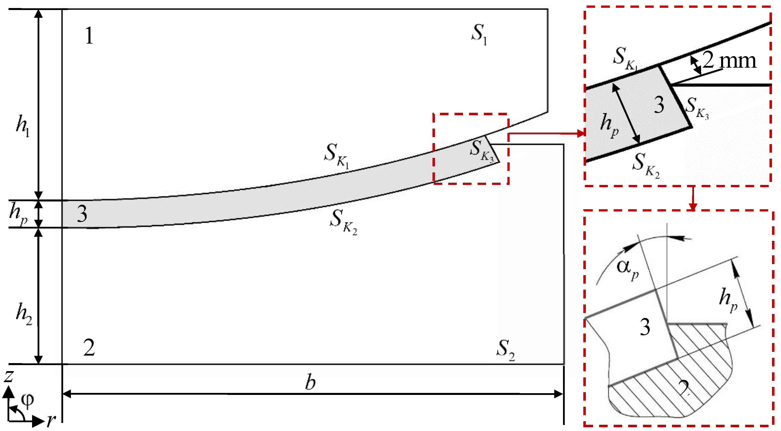
Figure 3.
Experiment on free compression of cylindrical samples: a is the experiment; b the equilibrium experimental curves.
Figure 3.
Experiment on free compression of cylindrical samples: a is the experiment; b the equilibrium experimental curves.
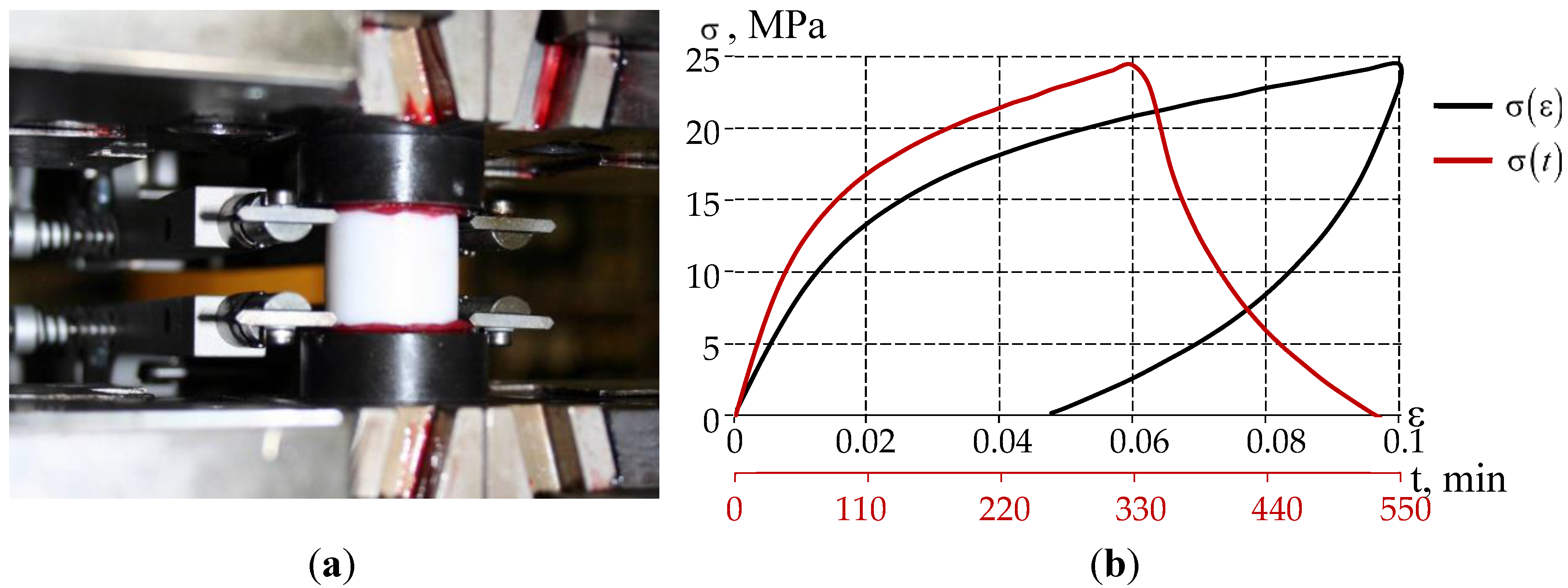
Figure 4.
Material models based on experimental data on the free compression of cylindrical samples: a is elastic-plasticity; b is viscoelasticity.
Figure 4.
Material models based on experimental data on the free compression of cylindrical samples: a is elastic-plasticity; b is viscoelasticity.
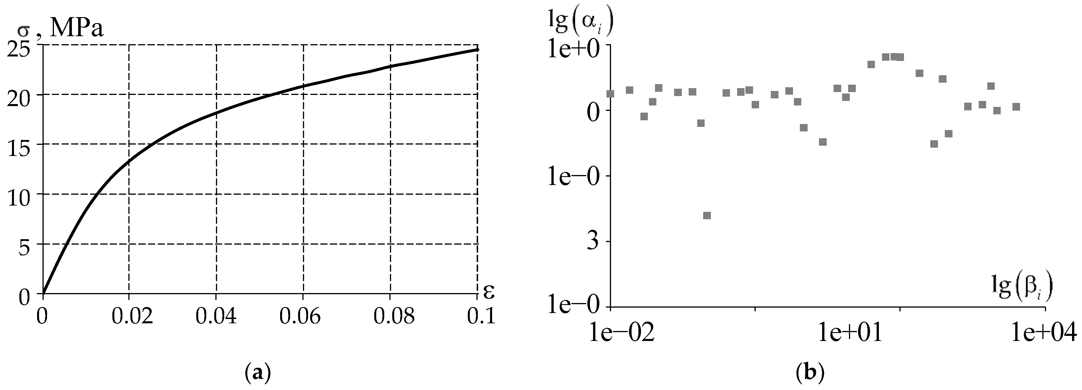
Figure 5.
Experiement on DMA: a is a three-point bend; b, c, d are samples.
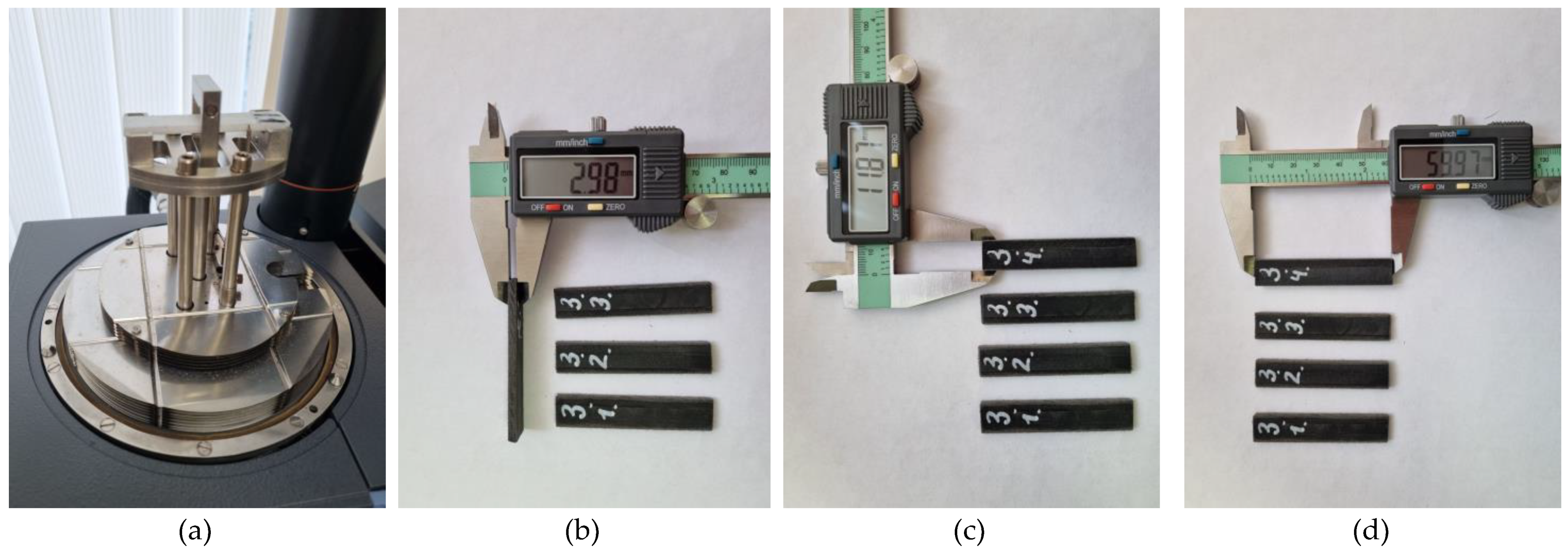
Figure 6.
Temperature dependencies of the material parameters: a is the storage modulus; b is the loss modulus; c is the loss angle tangent; black lines are the experimental data for a set of samples; red line is the averaged values of experimental data.
Figure 6.
Temperature dependencies of the material parameters: a is the storage modulus; b is the loss modulus; c is the loss angle tangent; black lines are the experimental data for a set of samples; red line is the averaged values of experimental data.
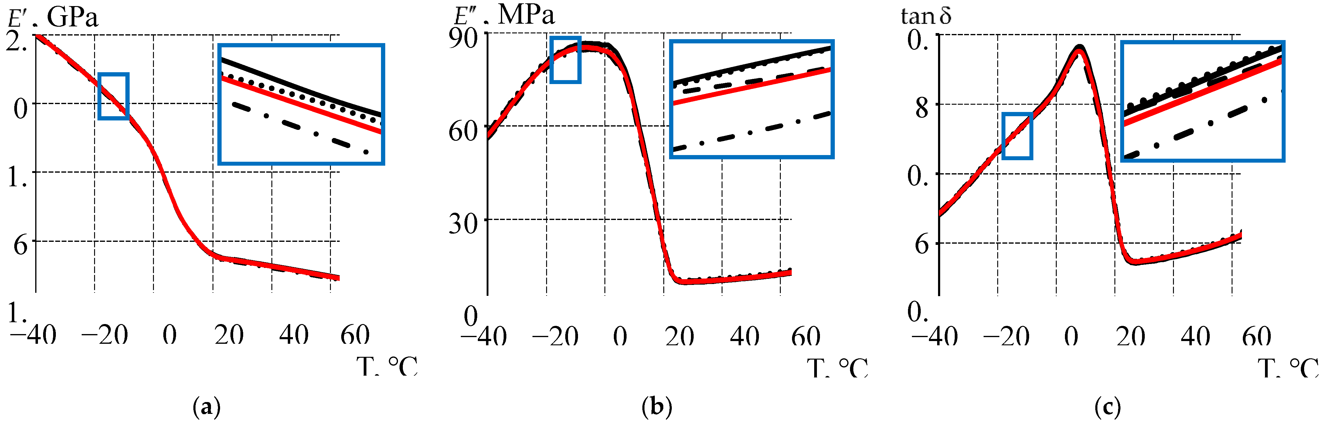
Figure 7.
A viscoelastic Maxwell-type model based on Prony series: a is Prony and WLF parameters; b is the dependence of the weighting coefficients on the relaxation time.
Figure 7.
A viscoelastic Maxwell-type model based on Prony series: a is Prony and WLF parameters; b is the dependence of the weighting coefficients on the relaxation time.
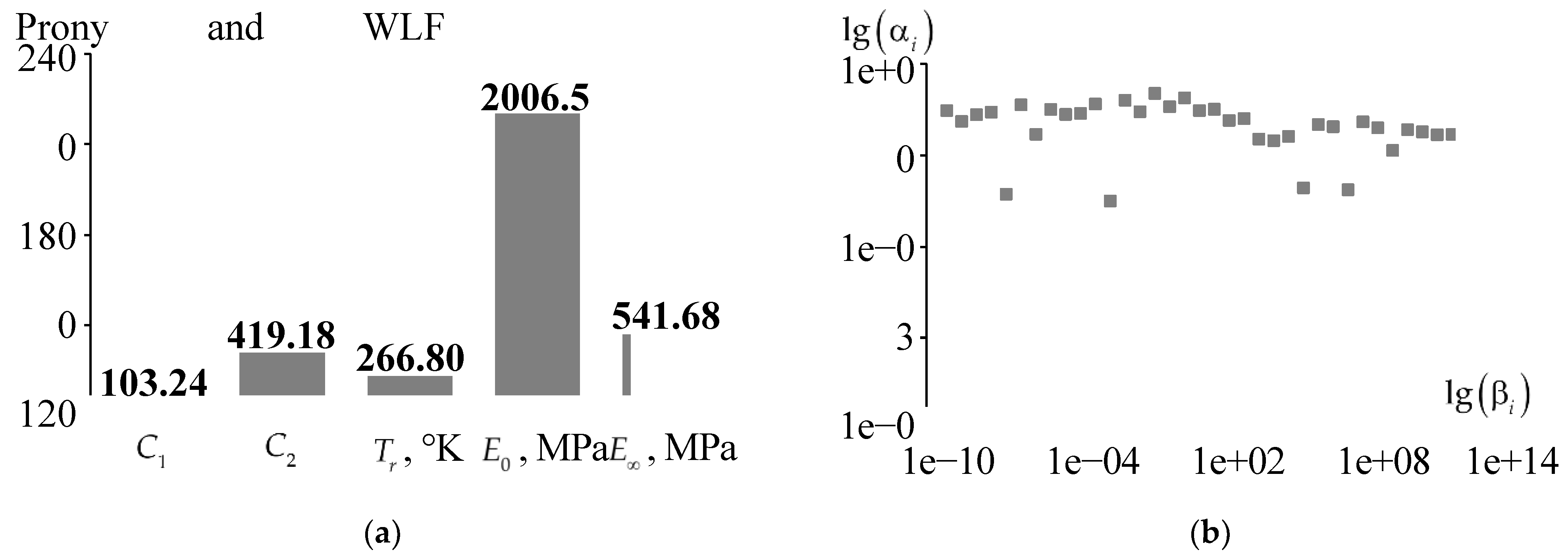
Figure 8.
Contact parameters with different conjugation : a is contact pressure; b is contact tangential stress; the solid line is ideal contact; the dashed line is full adhesion; dots are frictional contact.
Figure 8.
Contact parameters with different conjugation : a is contact pressure; b is contact tangential stress; the solid line is ideal contact; the dashed line is full adhesion; dots are frictional contact.
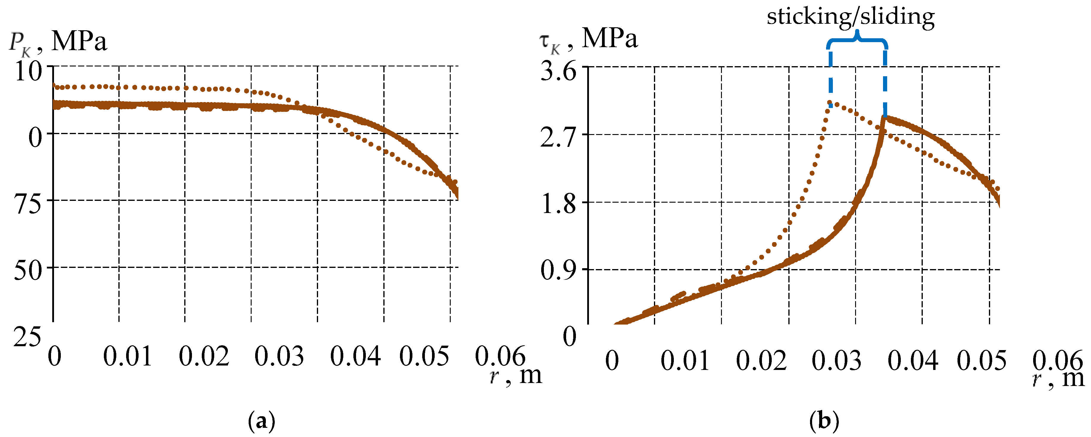
Figure 9.
Distribution of normal displacements along the end of the layer at different interfaces : the solid line is ideal contact; the dashed line is full adhesion; the dots are friction contact.
Figure 9.
Distribution of normal displacements along the end of the layer at different interfaces : the solid line is ideal contact; the dashed line is full adhesion; the dots are friction contact.
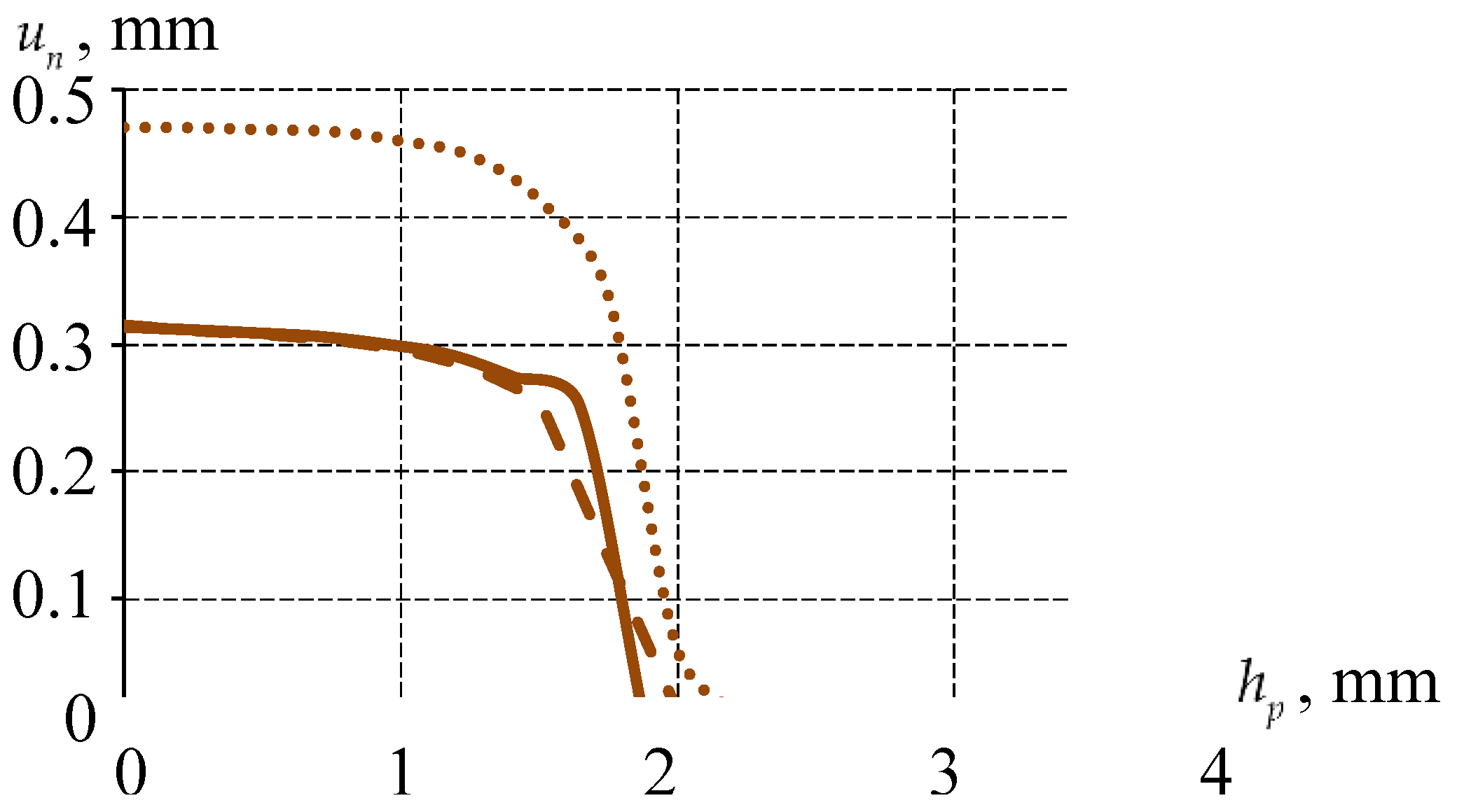
Figure 10.
The arithmetic mean differences of the contact parameters and normal displacements on .
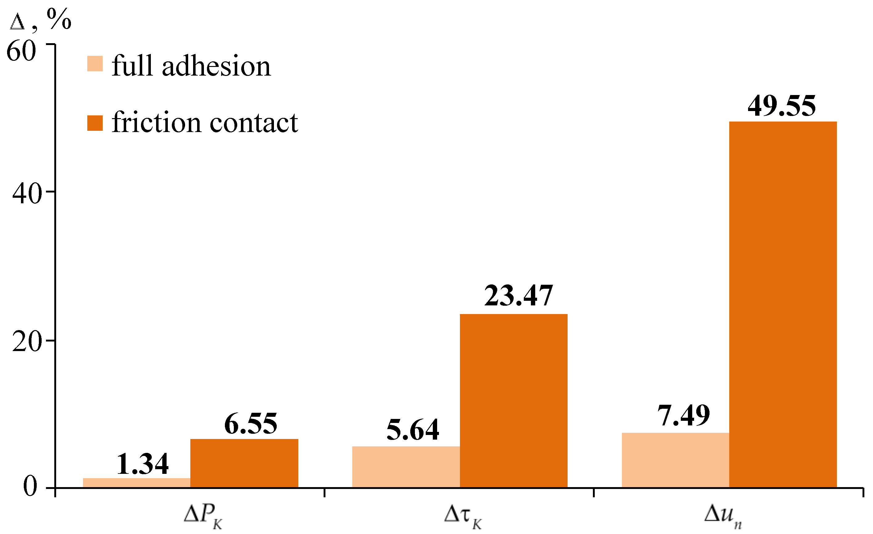
Figure 10.
The parameters of the stress-strain state of the sliding layer are: a, c, e are ; b, d, f are ; a, b are ideal contact ; c, d are full adhesion ; e, f are frictional contact .
Figure 10.
The parameters of the stress-strain state of the sliding layer are: a, c, e are ; b, d, f are ; a, b are ideal contact ; c, d are full adhesion ; e, f are frictional contact .
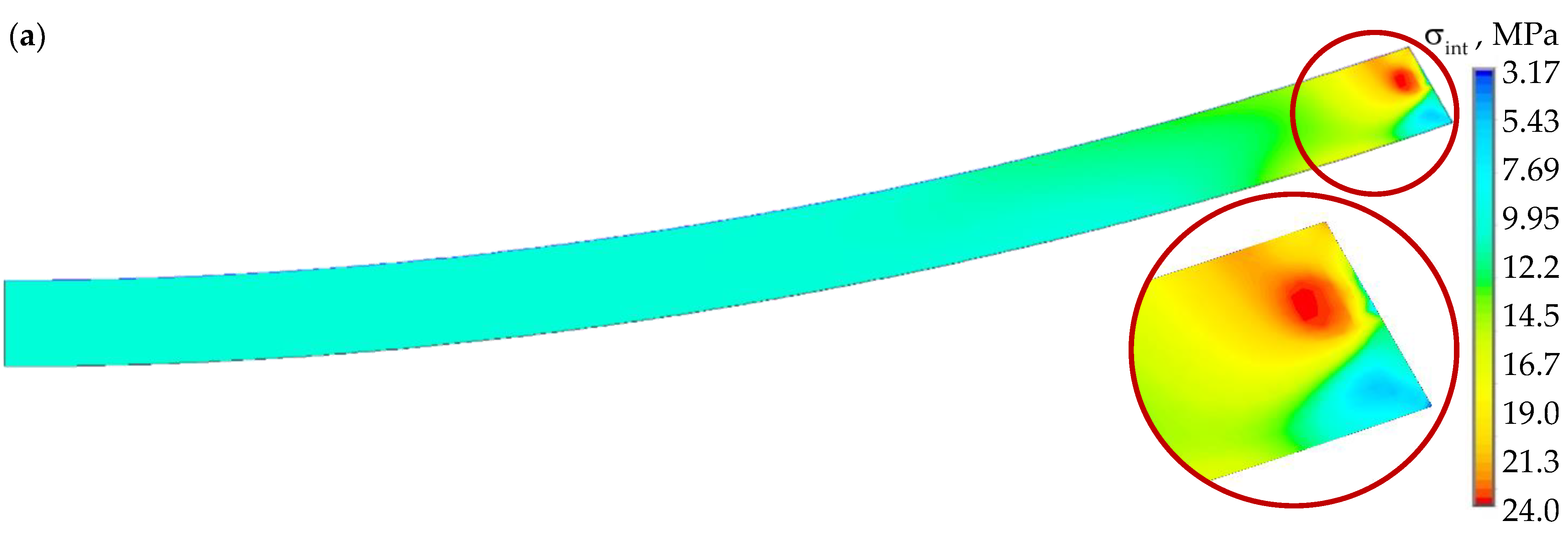
Figure 12.
Distribution of contact parameters on at different : a is contact pressure; b is tangential contact stress.
Figure 12.
Distribution of contact parameters on at different : a is contact pressure; b is tangential contact stress.

Figure 13.
Distribution of normal displacements along the end of the interlay at different thickness of the sliding layer.
Figure 13.
Distribution of normal displacements along the end of the interlay at different thickness of the sliding layer.
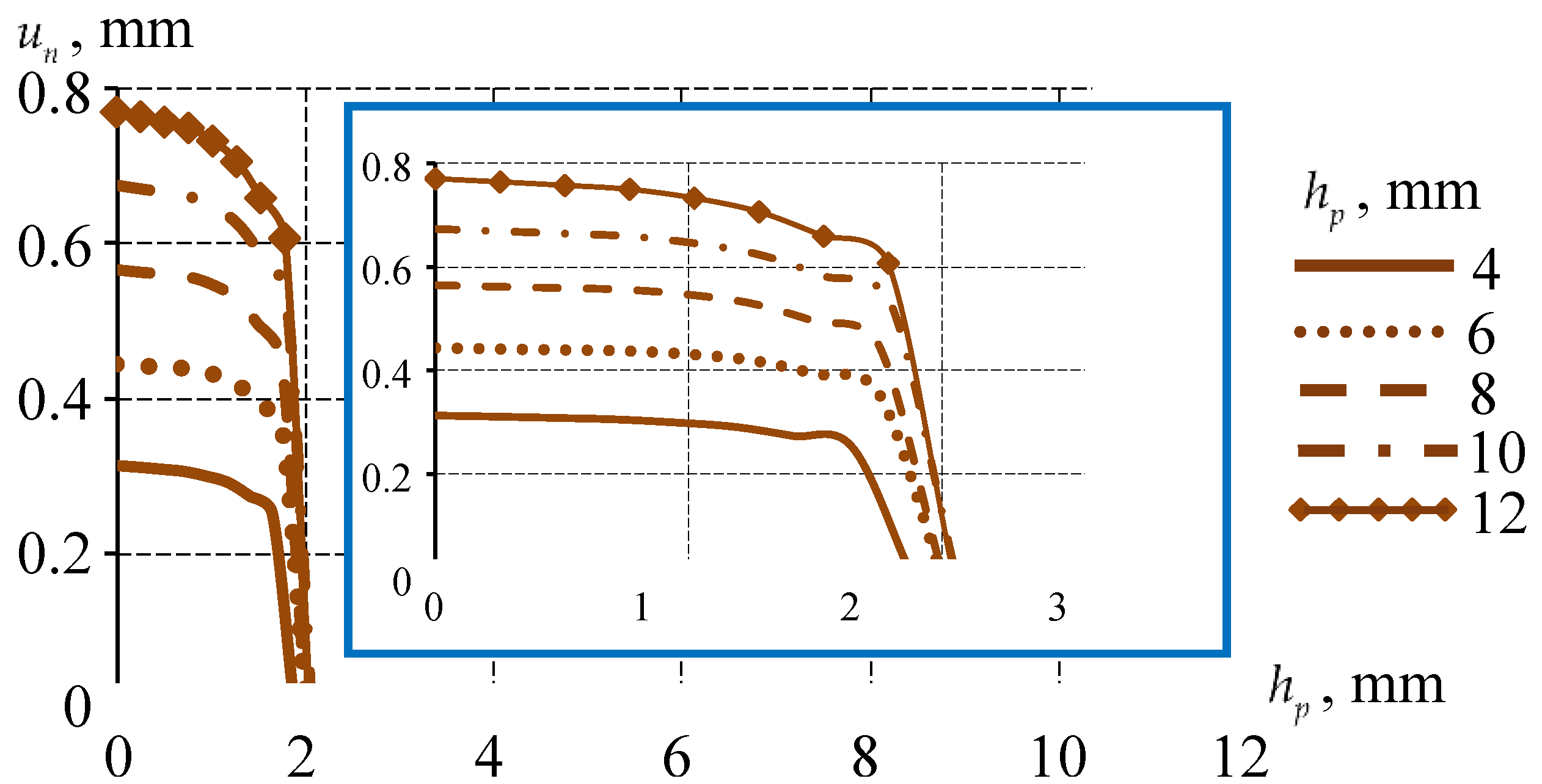
Figure 14.
Dependence of the contact stress-strain state parameters of the sliding layer on : a is at ; b is at ; c is at ; d is at ; the solid line is ideal contact; the dashed line is full adhesion; the dots are frictional contact.
Figure 14.
Dependence of the contact stress-strain state parameters of the sliding layer on : a is at ; b is at ; c is at ; d is at ; the solid line is ideal contact; the dashed line is full adhesion; the dots are frictional contact.
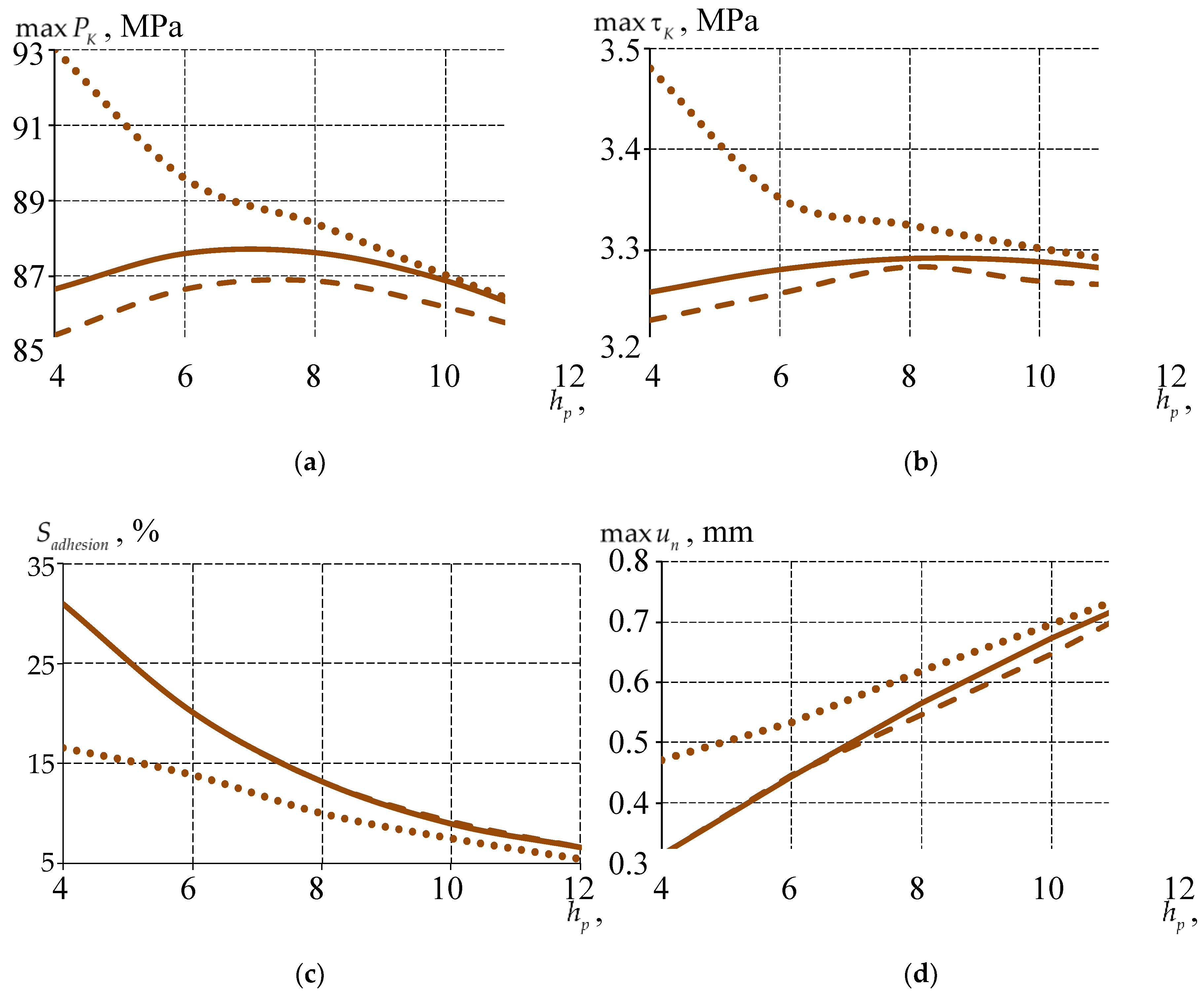
Figure 15.
The parameters of the stress-strain state of the bearing: a is at ; b is at ; c is at ; d is the settlement of the bearing.
Figure 15.
The parameters of the stress-strain state of the bearing: a is at ; b is at ; c is at ; d is the settlement of the bearing.
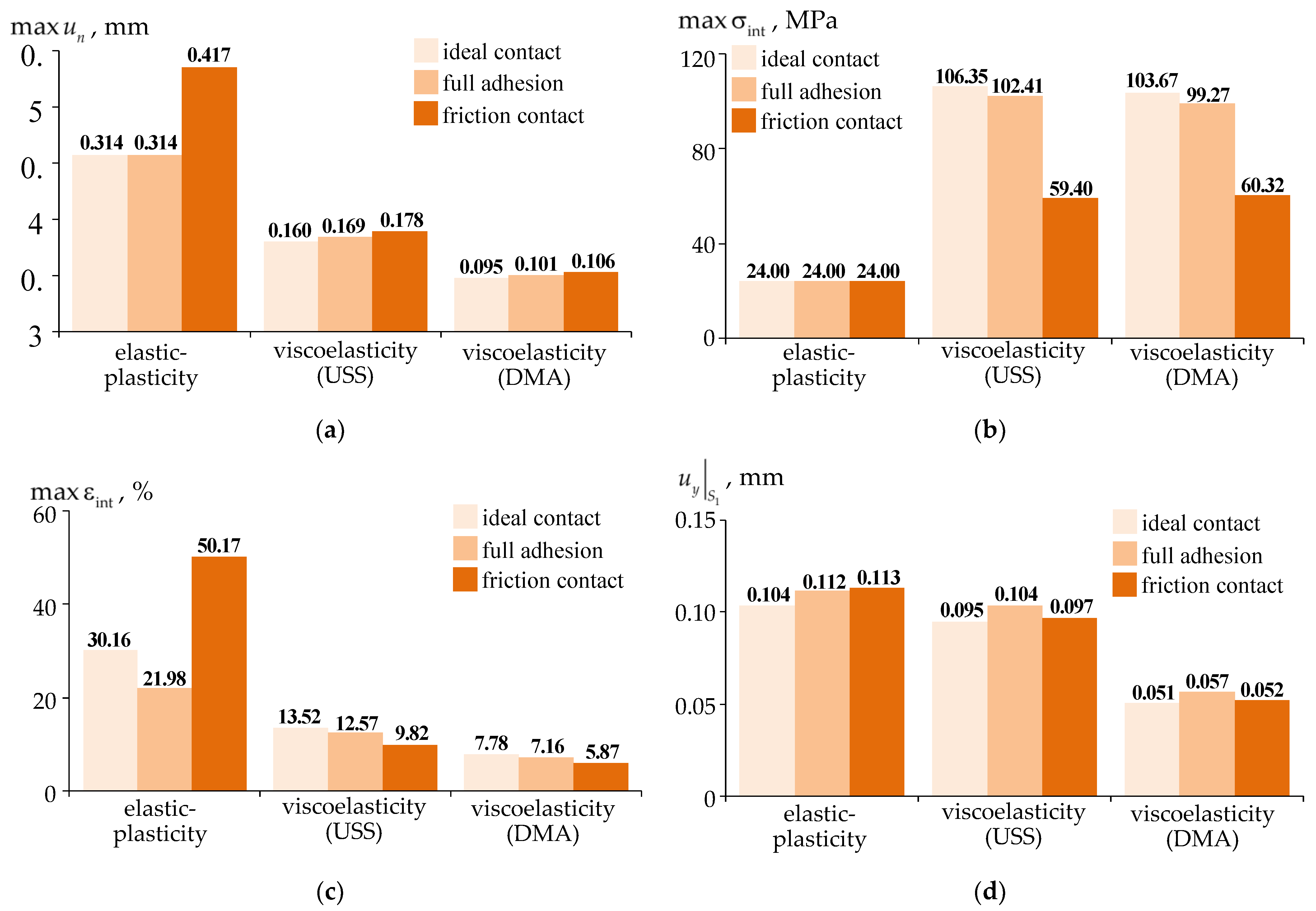
Figure 16.
Comparative analysis of the contact parameters at different conjugation and different models of the sliding layer material behavior: a is contact pressure; b is tangential contact stress; the solid line is ideal contact; the dashed line is full adhesion; the dots are frictional contact.
Figure 16.
Comparative analysis of the contact parameters at different conjugation and different models of the sliding layer material behavior: a is contact pressure; b is tangential contact stress; the solid line is ideal contact; the dashed line is full adhesion; the dots are frictional contact.
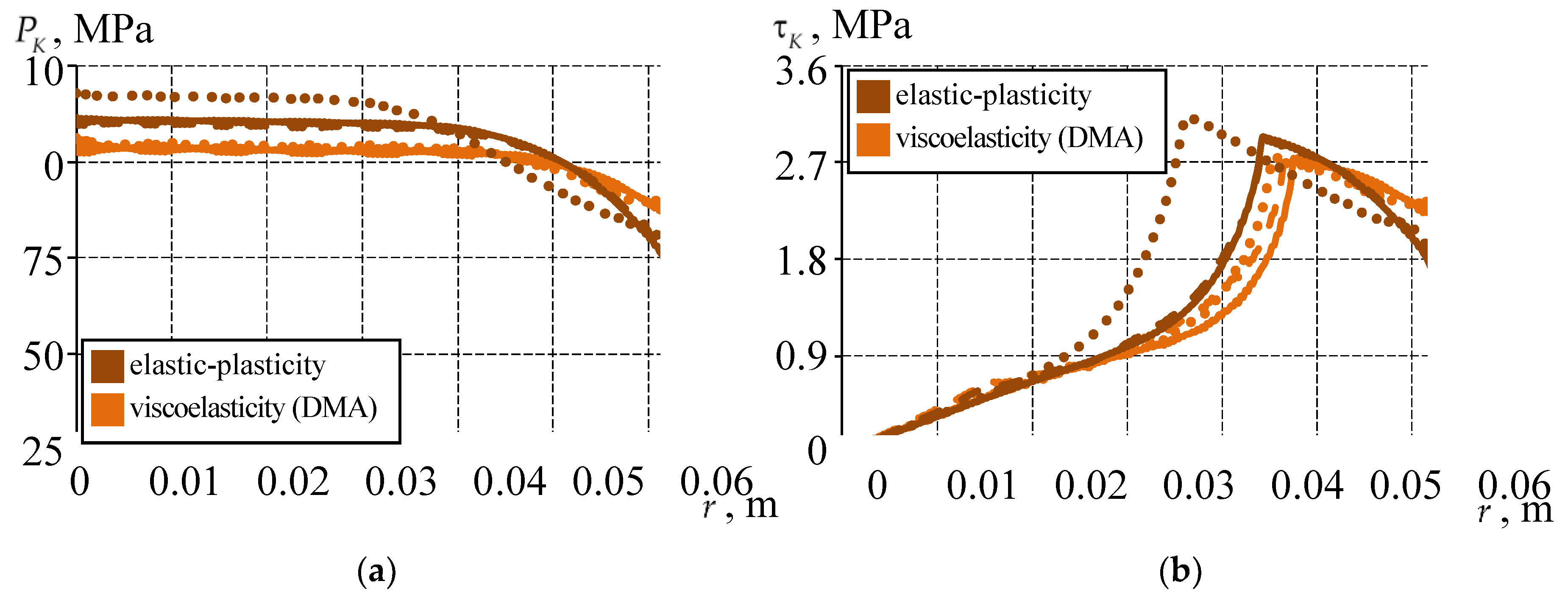
Figure 17.
Comparative analysis of the distribution of displacements along the normal of the end face of the interlayer at different conjugation and different models of behavior of the sliding layer material: the solid line is ideal contact; the dashed line is full adhesion; the dots are frictional contact.
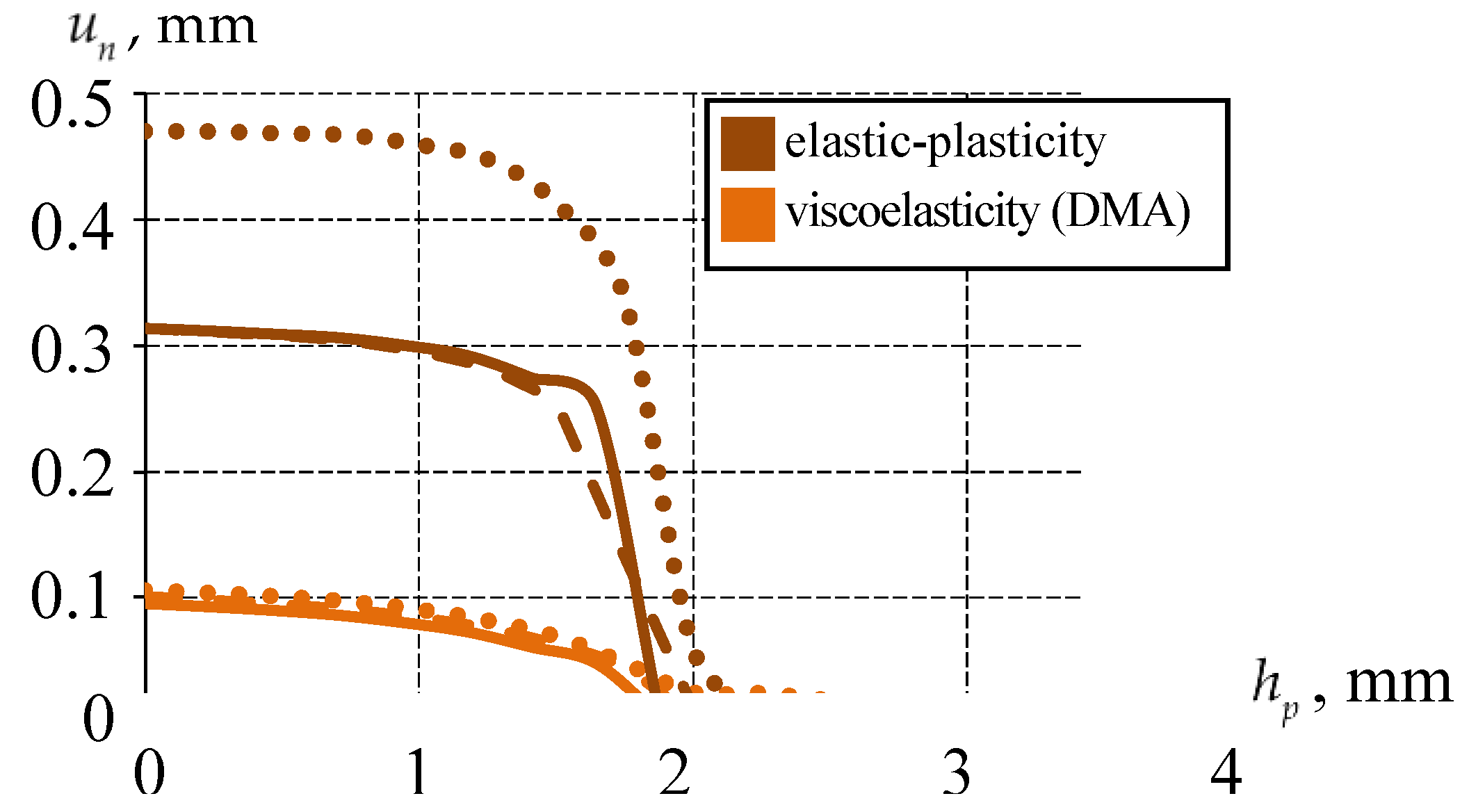
Figure 18.
The dependence of the parameters of the contact stress-strain state of the sliding layer on for elastic-plastic and viscoelastic models of the sliding layer material behavior: a is at ; b is at ; c is at ; d is the settlement of the bearing; the solid line is ideal contact; the dashed line is full adhesion; the dots are frictional contact.
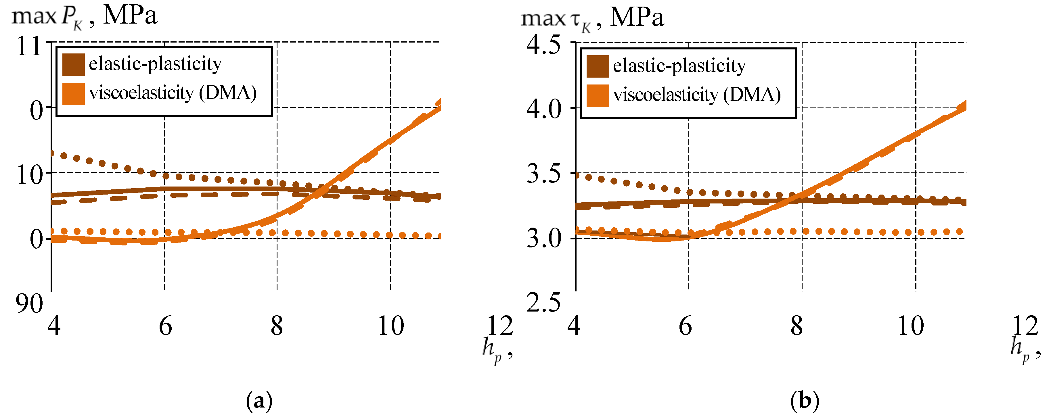
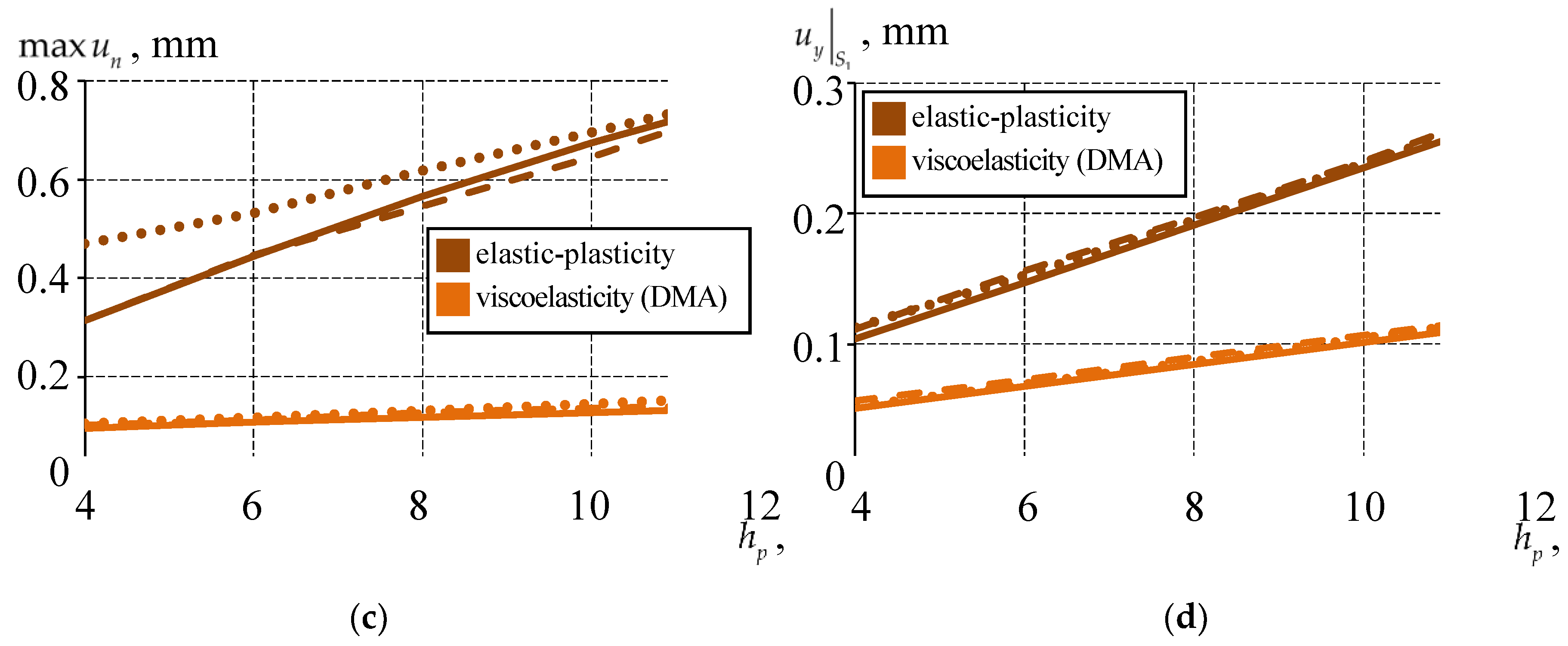
Figure 19.
The percentage of the contact surface area in the state of full adhesion depends on the thickness of the sliding layer: a is ; b is ; the solid line is ideal contact; the dashed line is full adhesion; the dots are frictional contact.
Figure 19.
The percentage of the contact surface area in the state of full adhesion depends on the thickness of the sliding layer: a is ; b is ; the solid line is ideal contact; the dashed line is full adhesion; the dots are frictional contact.
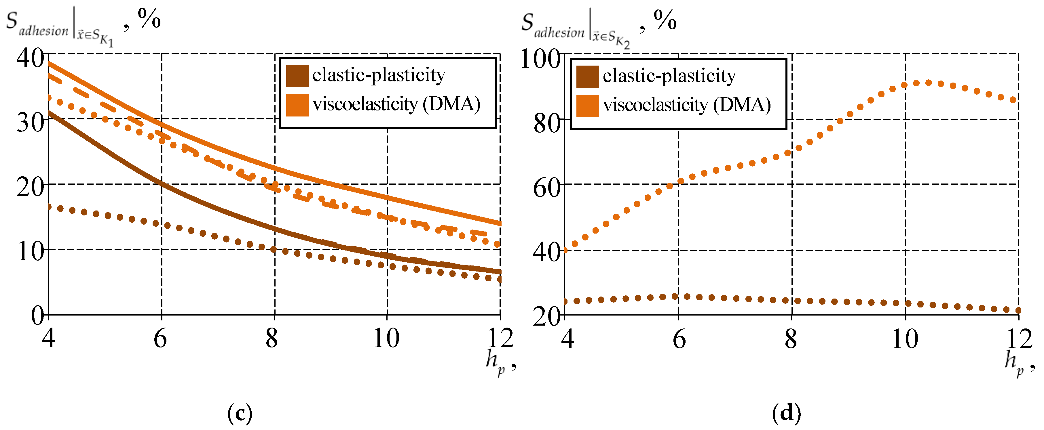
Figure 20.
Settlement of the supporting part during multi-stage loading.
Disclaimer/Publisher’s Note: The statements, opinions and data contained in all publications are solely those of the individual author(s) and contributor(s) and not of MDPI and/or the editor(s). MDPI and/or the editor(s) disclaim responsibility for any injury to people or property resulting from any ideas, methods, instructions or products referred to in the content. |
© 2025 by the authors. Licensee MDPI, Basel, Switzerland. This article is an open access article distributed under the terms and conditions of the Creative Commons Attribution (CC BY) license (http://creativecommons.org/licenses/by/4.0/).
Copyright: This open access article is published under a Creative Commons CC BY 4.0 license, which permit the free download, distribution, and reuse, provided that the author and preprint are cited in any reuse.


