Submitted:
31 August 2025
Posted:
01 September 2025
You are already at the latest version
Abstract
Employing commercial off-the-shelf coherent optical transmission components and methods to design a continuous variable quantum key distribution (CVQKD) system is a promising trend of achieving QKD with high security key rate (SKR) and cost-effectiveness. In this paper, we explore CVQKD system based on the widely used polarization division multiplexed coherent optical transmission structure and pilot-aided digital signal processing methods. A simplified pilot-aided phase noise compensation scheme based on frequency division multiplexing (FDM) is proposed, which introduces less total excess noise than classical pilot-aided schemes based on time division multiplexing (TDM). Besides, the two schemes of training symbol (TS)-aided equalization are compared to find the optimal strategy for TS insertion, where the scheme based on block insertion strategy can provide the SKR gain of around 29%, 22%, and 15% compared with the scheme based on fine-grained insertion strategy at the transmission distance of 5 km, 25 km and 50 km, respectively. The joint optimization of pilot-aided and TS-aided methods in this work can provide reference for achieving CVQKD system with high SKR and low complexity in metropolitan-scale applications.
Keywords:
continuous variable
; quantum key distribution
; polarization division multiplex
; digital signal processing
1. Introduction
Quantum key distribution (QKD) provides a novel approach to sharing secret keys between two communicating parties, which can achieve unconditional security when combined with the ‘one-time pad’ [1,2]. Although QKD technology has made considerable strides toward practical implementation over the past several decades, it still faces challenges that hinder further development, the most prominent of which are cost and the secure key rate (SKR). On one hand, the integration of QKD with deployed optic fiber network infrastructures has not yet met expectations, resulting in the high cost of current commercial QKD equipment [3]. On the other hand, the SKR of current commercial QKD devices remains at Kbps level, far below the Tbps capacity of modern communication systems [4]. Continuous variable (CV) QKD is considered a promising solution for addressing the two issues mentioned above due to its high key rate over metropolitan area and compatibility with commercial off-the-shelf components [5].
In a typical CVQKD protocol, Alice modulates key information on the quadratures of coherent states and sends it to Bob through a lossy channel. Then Bob recovers the raw keys from the received signal by using coherent detection such as homodyne or heterodyne detection [6,7]. This structure of CVQKD shows high similarity to the widely deployed coherent optical transmission systems, indicating the prospect of high-performance and cost-effective QKD system once the state-of-the-art methods of existing coherent optical transmission systems can be effectively adopted for CVQKD [8,9]. Actually, the research on CVQKD schemes is just developing in this direction. For example, compared with the early proposed Gaussian-modulated coherent states (GMCS) protocol, the discrete-modulated coherent states (DMCS) protocol uses more efficient modulation formats such as quadrature amplitude modulation (QAM) and thus can be implemented with more efficient forward error correction (FEC) algorithms as well as fewer quantization bits for digital-to-analog converters (DACs) and analog-to-digital converters (ADCs) [10]. Besides, it has been attractive to use traditional continuous wave (CW) light instead of pulsed light to support a higher SKR and a more accurate track of the phase noise [11]. Moreover, the emergence of schemes based on a local local oscillator (LLO) also shows advantages over transmitted local oscillator (TLO) schemes, making it feasible to directly use integrated coherent receivers [12]. It is worth noting that the experimental demonstrations of CVQKD system based on CW light have achieved sub-Gbps SKR within metropolitan area [13].
Regarding the pursuit of higher-SKR CVQKD, polarization division multiplexing (PDM) can also be introduced to achieve a potential SKR of Gbps-level. The investigation of PDM in CVQKD systems was initially used to transmit reference signals in LLO systems [14]. More recently, PDM CVQKD systems that transmit QKD signals in both polarization states show promising feasibility mainly because that the hardware structure of classical dual-polarization coherent optical transmission system can be well migrated with only slight adjustment [8,15]. Whereas the challenge of these systems is the signal processing. On one hand, auxiliary signal is typically needed to recover raw keys signal from weak and noisy QKD signal, either by adding FDM pilot signal or TDM training symbols to QKD signal [16,17]. The performance of such pilot aided schemes in PDM CVQKD system need to be revaluated. On the other hand, the PDM CVQKD induced extra Impairments such as polarization noise [18,19], thus corresponding digital signal processing (DSP) algorithms should be designed to compensate these impairments. The influences of these algorithms on the performance of CVQKD need to be analyzed.
In this paper, we investigate PDM-CVQKD based on the structure of classical coherent optical transmission system, where the CW-GMCS-LLO scheme is applied. Firstly the structure of PDM-CVQKD system is established and the main DSP methods for the system is introduced. Then, a simplified FDM pilot-aided signal processing scheme is proposed for carrier frequency offset (FO) estimation and phase noise (PN) compensation. The excess noise corresponding to the FDM pilot-aided scheme is also modeled in comparison with the traditional TDM pilot-aided scheme. Besides, the two strategies of TS-aided equalization scheme are compared to find the optimal option of the insertion of TS depending on the channel situation. Lastly, the SKR of the PDM-CVQKD system at different transmission distances is evaluated based on the joint optimization of the setup of pilot-aided PN compensation and TS-aided equalization.
2. System Architecture and Digital Signal Processing Methods
2.1. Transmission Structure
Figure 1 shows the structure of PDM-CVQKD system based on coherent optical transmission components. At transmitter side, Alice exploits a CW laser source to generate the optical carrier. A polarization beam splitter (PBS) is then used to divide the optical carrier into two orthogonal polarization states. For each polarization, an in-phase-and-quadrature (IQ) modulator consisting of two Mach-Zehnder modulators (MZM) and a phase modulator (PM) modulates the baseband electrical signal generated by transmitter side digital signal processing (Tx-DSP) onto the optical carrier, followed by a variable optical attenuator (VOA) to modify the output power of the modulated signal to make sure that the mean photon number of each optical pulse is sufficiently small for security. Later, the output signals of two VOAs are multiplexed by a polarization beam combiner (PBC) and transmitted over a single mode fiber (SMF) channel. At receiver side, the PDM signal firstly passes through a polarization controller (PC) to initially eliminate the rotated state of polarization (RSOP) during fiber transmission and is then separated by a PBS into two separate parts. Here Bob exploits another CW laser source to supply the LO signal of polarization-diversity coherent receiver, which consists of two heterodyne detectors. Subsequently, the outputs of PBS are demodulated by the heterodyne detectors and lastly processed in the receiver side (Rx) DSP module to further compensate the impairments of the demodulated baseband electrical signal and distill secret keys.
2.2. DSP Methods of Transmitter and Receiver
For the PDM-CVQKD system in Figure 1, it is similar to classical coherent optical transmission that some impairments will be induced by the imperfections during the transmission. For example, the frequency offset between two lasers of Alice and Bob as well as the linewidth of two lasers will induce phase noise. Besides, the polarization mode dispersion and RSOP in fiber will cause crosstalk between the signals of two polarizations [20]. As we already pointed out, CVQKD signal is transmitted under very low SNR, thus is vulnerable to these impairments. In this case, it is essential to propose corresponding signal processing schemes. A common scheme follows the approach of transmitting the quantum signal together with the pilot signal using signal division multiplexing methods [21,22]. In our work, we consider a pilot-aided DSP scheme that is based on frequency division multiplexing, as depicted in Figure 2. In this scheme, a single frequency pilot tone with different frequency bands of quantum signal is used for compensating the phase noise, as shown in the lower left inset of Figure 2, where only one pilot tone in the vertical polarization (V-pol) is needed for both the quantum signals of vertical polarization and horizontal polarization (H-pol), which can reduce the crosstalk of pilot to QKD signal. Besides, since the pilot tone is in the different frequency band of QKD signal, the polarization crosstalk can not be efficiently compensated by using the pilot tone. As a result, Quadrature Phase-Shift Keying (QPSK) training symbols with higher power can be inserted to the QKD symbols for channel equalization and polarization de-multiplexing, as shown in the upper left inset of Figure 2.
To perform the pilot-aided scheme, the DSP flow is designed as follows: at the transmitter (Alice) side, for each polarization, random bits are generated and mapped into Guassian distributed symbols, then the QPSK modulated training symbols are inserted into the signal. The signal is then up-sampled and pulse shaped using a Root-Raised Cosine (RRC) filter to minimize inter-symbol interference (ISI). Subsequently, the baseband signal is then up-converted to an intermediate frequency to reduce the low frequency noise and the pilot tone is added. At the receiver (Bob) side, two independent bandpass filters are employed to isolate the quantum signal and the pilot tone, ensuring minimal cross-talk and out-of-band noise interference. The filtered QKD signal is then down-converted to baseband. Subsequently, the FO between Alice’s and Bob’s lasers is estimated by performing fast Fourier transform (FFT) on the pilot signal and estimate by:
where is the peak frequency of the FFT spectrum, is the frequency of transmitted pilot tone. Then, based on the measured , the PN can be estimated as:
where and are the phase drift caused by the linewidth of lasers as well as the phase drift occurs during the channel transmission, respectively. is the estimation error induced by the noise on the pilot tone. is the complex pilot symbols after bandpass filtering. It is noteworthy that in our FDM-based pilot scheme, and of pilot tone and quantum signal are identical, thus can be well compensated. Whereas the estimation error will induce residual phase noise, resulting in an excess noise in practice. After the pilot-aided FO and PN compensation, an RRC matched filter is employed to initially eliminate inter-symbol interference (ISI). Subsequently, the QPSK training symbols-aided (TS-aided) equalization and polarization demultiplexing is operated to compensate the ISIs that is caused by the polarization-dependent impairments. The most dominant polarization-dependent impairment that undermines the performance of PDM-CVQKD system is the RSOP, which can be described using Jones Matrix as:
where is the phase difference of two polarization, is the polarization state rotation angle, which is time-varying during transmission and induce excess noise. To compensate the RSOP impairment, butterfly adaptive equalizers can be used to achieve the inverse matrix of , defined by:
where , , , are the coefficients of four finite impulse response (FIR) filters. The structure of the equalizer is shown in the right insert of Figure 2, where a butterfly filter structure is employed to construct the matrix in Equation (2). Depending on the difference of cost function of the equalizer and the filter coefficients update function, numerous algorithms have been derived, among which the constant modulus algorithm (CMA) is the most widely used [23]. In our scheme, the TS-aided equalization based on CMA is utilized. As for the insertion of TS in QKD symbols, there are mainly two schemes that are widely used. Scheme A employs a fine-grained insertion strategy, as shown in Figure 3(a), where TS and QKD symbols are alternatively transmitted, i.e. inserting one TS before each QKD symbol. Such interleaving scheme can provides optimal compensation of RSOP, especially in rapidly varying channels. However, this scheme exhibits several drawbacks. On one hand, the high density of TS symbols in this scheme results in high overhead, limiting the SKR. On the other hand, it is rather challenging to achieve rapid and precise control over the power levels of TS and QKD symbols in CW system. Scheme B operates a block-based TS insertion which offers the trade-off between RSOP compensation and spectral efficiency, as shown in Figure 3(b), where the N received symbols of each blocklength are divided into k sequences of M symbols, each set of M symbols are then divided into training symbols and QKD symbols. For each M symbols, the TS are utilized to make the equalizer’s coefficients converge to be optimal. These optimized parameters are then employed as the initial settings for processing the QKD symbols. The value of parameter k and can be adaptive according to the actual channel situation. Compared with scheme A, scheme B may provide sub-optimal equalization performance but higher spectral efficiency and more flexibility in implementation. A detailed and comparative analysis of the two schemes’ performance will be presented in section 4. After the TS-aided equalization, critical system parameters such as channel transmittance and excess noise are estimated to evaluate the performance of quantum channel and SKR is evaluated using the estimated parameters and the covariance matrix in entanglement-based (EB) model [20].
2.3. Noise Configure and SKR Calculation
After Bob’s detection as well as the DSP of the noisy quantum signal, the symbols that Bob obtained can be expressed as:
where are the transmitted symbols with modulation variance . T is the transmittance of optical link and is the quantum efficiency of heterodyne detector. is the additive noise with variance , where is the shot noise. Note that when signals are normalized to shot noise unit (SNU). is the excess noise corresponding to Alice side, which is mainly composed of the noise corresponding to the imperfection of transceiver, channel and residual impairment after receiver’s DSP operations. is the electronic noise of detectors. To establish the security of the protocol, it is normally assumed that Eve controls the transmittance T and the excess noise . The security of CVQKD is evaluated by the lower bound of the information that Alice and Bob can obtained, i.e. the SKR, which can be expressed as:
where is the symbol rate, is the proportion of pilot symbols, denotes the mutual information between Alice and Bob, is the reconciliation efficiency and is the Holevo information that eavesdroppers can obtain form Bob. The detailed expression of SKR for GMCS protocol is derived in [20], which is also employed for the numerical simulation in this work. Note that the value of and are determined by the value of parameters such as , T, , and , which means that it is essential to precisely estimate these parameters to evaluate the actual SKR. In particular, the calibration of can be rather important for the initial setup of commercial CVQKD system, whose accuracy determines whether the transmitted QKD signal remains in a valid quantum state. Besides, the vary of circumstance can result in the change of these parameters in time, which should also be taken into account in practical implementation.
3. The Effects of FDM Pilot-Aided Scheme on Security Parameter Estimation
As previously mentioned, a critical prerequisite for secure key generation in QKD system is the accurate estimation of security parameters at the receiver. In practical operation, the security parameters such as , , can be calibrated at receiver and regarded as fixed when the system is stable. However, the estimation of parameters such as , T and may be affected by the imperfections of the transceiver, such as impairments induced by the pilot tone as well as the non-optimize of DSP algorithms. In this section, we focus on the impact of pilot-aided DSP schemes on the estimation of security parameters. First of all, a numerical simulation system based on the scheme in Figure 1 and Figure 2 is established. The main parameter setup is shown in Table 1, where the symbol rate of quantum signal is set to 2 Gbaud, the central frequency of quantum signal is up-converted to 1.5 GHz to avoid low-frequency noise and the frequency of pilot tone is set to be 3.5 GHz to reduce the crosstalks in frequency domain. Note that the shot noise as well as the electronic noise are regarded as Guassian white noise with variance of . For convenience of analysis we assume that the shot noise variance of each heterodyne detector are equal, which can be given by:
where e is the elementary charge, is the bandwidth of receiver, is the optical power of LO, h is the Planck constant, is the central frequency of lasers.
Firstly, extra impairments will be induced by the pilot tone at transmitter. For example, the calibration of modulation variance may be effected because the nonlinear effects of MZMs may be amplified when strong pilot is used. Normally, the value of can be calculated by , where is the average photon number of the transmitted optical signal, which can be estimated by measuring the output optical power at transmitter. In our scheme, the output signal of H-pol only consists QKD signal, so can be estimated directly from the output power. Whereas for V-pol, the output signal consists both the QKD signal and pilot tone, resulting in the inability to directly measure output power of QKD signal. Therefore, once the power ratio of pilot tone to quantum signal is given, where and are the mean voltage of electronic quantum signal and electronic pilot tone assigned to MZM. In this case, of V-pol can be indirectly estimated by:
can also be estimated at receiver in back to back (B2B) situation, i.e. under a fixed transmittance of . In this case, can be estimated as:
where x is the transmitted symbols that is not normalized to SNU, y is the received symbols that is normalized to SNU. Figure 4 shows the of V-pol and H-pol estimated at transmitter/receiver with different (in dB), where the initial of each polarization are set to 5 in SNU. Note that the QPSK training symbols are not inserted here for simplicity and the results are averaged over 20 acquisitions of received symbols for enough precision. The results indicated that the estimated of H-pol is matched either estimated at transmitter or receiver. However, for V-pol, estimated at transmitter is no longer accurate with the increase of , mainly because the used in Equation (8) is the power ratio of baseband electrical pilot tone and quantum signal, which is not the actual of the output optical signal due to the nonlinear effect of IQ modulators when the power of pilot tone is high. In particular, the nonlinearity grows more pronounced with the increasing of , as depicted by the star-marked yellow curve in Figure 4. As a result, it is feasible to calibrate at transmitter when is at a relatively low level, whereas more appropriate to perform the calibration of at the receiver when is high in practical implementation.
The modulation-related excess noise under the impact of pilot tone is also evaluated as shown in Figure 5, where the nonlinearity as well as limited dynamic range of MZM is taken into account. Note that the at each are all normalized to 5 for the convenience of comparison and the transmission distance is 20 km. The nonlinear effect of MZM can induce the excess noise of when no pilot is added. Whereas when the pilot is modulated together with QKD signal, the excess noise increases, especially with the increasing of and . For example, the excess noise of is induced at the typical of 50 mV and of 20 dB. It means that the FDM pilot tone can cause extra modulation-related excess noise which can not be ignored, which is more dominant compared to the schemes without using FDM pilot. As for the effect of limited dynamic range of MZM, it has been shown that the limited extinction ratio (ER) of amplitude modulator may cause the increasing of excess noise for the pilot-aided schemes based on TDM [18]. The simulation results in Figure 5 shows that the limited ER of MZM will not lead to extra excess noise in the FDM pilot-aided scheme.
Another important factor that affect security parameter estimation of pilot-aided scheme lies in the interference of the pilot tone on the quantum signal due to the employing of non-ideal band-pass filter. For the pilot-aided scheme in Figure 2, the filtered quantum signal of V-pol will contain residual pilot tone components, resulting in parameter estimation errors and an increase of excess noise in the system. In our simulation, the band-pass filter we adopt is a classical FIR filter based on Hamming window. Figure 6 gives the curve of estimated T and excess noise of each polarization with respect to the bandwidth of band-pass filter after 20 km transmission, where the filter order is set to be 20 for the curves unmarked and 50 for the curves using dot marks. The simulation results indicate that there exist an optimal bandwidth of FIR filter that can achieve the unbiased estimation of . The excess noise induced by non-ideal filter is about for V-pol and for H-pol.
Furthermore, as mentioned before, the implement of pilot-aided PN estimation and compensation can not be perfect in practice because of the estimation error in Equation (2). According to the research in [12], the residual excess noise induce by in TDM pilot-aided schemes can be estimated by:
where is the total noise of the pilot tone, is the amplitude of the pilot tone in SNU. However, for FDM pilot-aided scheme, the total noise of pilot tone is not equal to that of QKD signal because the noise bandwidth of received pilot tone and QKD signal are different. In this case, is given by:
where is the total noise of FDM pilot tone, and are the bandwidth of filtered QKD signal and filtered pilot tone, respectively. In TDM pilot-aided system, and are equal, while is much less than in FDM pilot-aided system when narrow-band filter is used to filter the pilot tone. As a result, is much less than . The total excess noise induced by pilot tone in each polarization can be eventually calculated as:
Figure 7 shows the excess noises mentioned in (12) with respect to at the transmission distance of 20 km. The total linewidth of CW and LO are set to 1e4 Hz, the bandwidth of bandpass filter is set to be approximately 2.75 GHz for QKD signal and 55 MHz for pilot tone. The result shows that the is minimized to 2.8e-3 at the of 20 dB. The corresponding is 1.5e-3. The estimated is 1.4e-3 for both polarization states, which is almost 50 times less than . Note that and are neither related to transmission distance, whereas is increased as the transmission distance increases. It means that the most dominant excess noise induced by pilot tone is for V-pol and only for H-pol.
4. Strategy Optimization of TS-Aided Equalization
Compared to the FDM pilot-aided phase noise compensation, the TDM-based TS-aided equalization and demultiplexing scheme achieves RSOP compensation at the expense of reduced QKD spectral efficiency. Therefore, to achieve the optimal SKR, it is necessary to optimize the equalizer parameters while adaptively selecting the optimal TS rate depending on the channel conditions. In this section, the performance of two TS-aided equalization schemes shown in Figure 3 are numerically compared to find the optimal strategy of TS insertion, thereby optimize the SKR of QKD system taking into account the impacts of pilot-aided scheme analyzed in section 3. For scheme A, the parameter is fixed to 0.5, as a result, only the equalizer’s parameters such as the tap number and step size u of CMA algorithm are needed to be optimized. Figure 8 shows the excess noise of scheme A with respect to different and u, where the RSOP is set to be 1e4 rad/s and the transmission distance is 20 km. Note that only the excess noise related to equalization is analyzed here, so that the parameters corresponding to the pilot tone are set to be ideal to make . It can be observed that the lowest excess noise of can be achieved with and . Based on the same parameter setup of equalizer, the lowest excess noise of can be achieved as well. Apparently, scheme A can effectively compensate RSOP once the parameter of equalizer is optimized.
As for scheme B, each N symbols are divided into k blocks of length M and TS are then used for the convergence of CMA equalizer. For each symbols, the lowest excess noise can be achieved by jointly optimizing the value of , and u. The total excess noise related to equalizer, denoted by , can be obtained by averaging the excess noise of k blocks. Following this strategy, the of each k blocks with different are simulated as shown in Figure 9, where the blocklength N is set to 1e5 and k is set to a fixed value of 5 for simplicity. To maintain consistency with scheme B, the parameters of equalizer are set by and for both TS and QKD symbols. The results show that for each value of , increases with the increasing of symbol number, mainly because of the accumulation RSOP effect over time. It can also be seen that the mean value of decreases with the increasing of , specifically, the mean value of when is 6e-3 for scheme B, which is higher than the value of 4e-3 for scheme A.
Since the value of in Scheme A is fixed to 0.5, its and SKR are constant at a specific distance. However, the value of in scheme B can be adapted to achieve the highest SKR. As a result, the strategy of scheme B can be optimized by traversing the total excess noise of each polarization with different to find the highest SKR, where the total excess noise of each polarization is defined by:
where an original system excess noise of is added to simulate the fixed excess noise contributed by the noise relative intensity noise of lasers, quantisation noise of ADC, nonlinear noise of the MZM, etc. Note that the is given by the value in Figure 7. Figure 10 shows the and SKR of scheme B with respect to different , with the transmission distance is 20 km. The and SKR of scheme A are also given to compare the performance of the two schemes. The results in Figure 10 confirm that at the transmission distance of 20 km, scheme B can achieve higher SKR than scheme A by choosing the optimal , even though the excess noise is much higher.
Based on the optimized strategy, the total excess noise and the corresponding optimal that maximize the SKR of scheme B at different transmission distances for both H-pol and V-pol can be obtained, as shown in Figure 11, where the of scheme A are also depicted for comparison. For scheme A, increases with the increase of transmission distance and the proportion of and are equivalent because scheme A can achieve the minimum excess noise induced by RSOP. Whereas for scheme B, exhibits a trend of first decreasing and then increasing with distance, and dominates the total excess noise because of the non-optimal compensation of RSOP compared to scheme A. The occurrence of the trend for scheme B is primarily because that the increasing of results in the fast decreasing of for short transmission distances while the slow decreasing of for long transmission distances, which can also be seen from the results in Figure 10. Meanwhile, is higher than for both scheme A and scheme B because of the extra excess noise induced by the pilot tone in V-pol. Besides, the optimal also increases with the increase of transmission distance.
Finally, to evaluate the overall security of the system, the SKR (in bit/symbol) of scheme A and scheme B at different transmission distances are given in Figure 12, where the SKR of H-pol and V-pol are calculated both individually and summed. The results show that scheme B can obtain higher SKR than scheme A for the transmission distances less than 55 km and lower SKR for the transmission distances more than 55 km. For example, the total SKR of around 0.67 bit/sample, 0.11 bit/sample, 0.015 bit/sample can be achieved for scheme B and 0.52 bit/sample, 0.09 bit/sample, 0.013 bit/sample for scheme A at the transmission distances of 5 km, 25 km and 50 km, respectively. Considering the baud rate of 2 Gbaud, the corresponding SKR in bps are 1340 Mbps, 220 Mbps, 30 Mbps for scheme B and 1040 Mbps, 180 Mbps, 26 Mbps for scheme A at the transmission distances of 5 km, 25 km and 50 km, respectively. It can be figured out that scheme B can realize the SKR gain of around 29 %, 22 %, and 15 % comparing to scheme A at the transmission distance of 5 km, 25 km and 50 km, respectively, which are significant for metropolitan-scale applications. In practical implementation, the noise level and the parameters may vary a lot, but the results shows a strategy of realizing the optimal performance with simplified DSP method. In addition, as shown in the inset of Figure 12, the extra excess noise induced by the pilot tone in V-pol results in insignificant SKR loss compared with H-pol, which further proof that the FDM-based pilot-aided scheme contributes few impact on the performance of the system.
5. Discussion
- The calibration of in pilot-aided CVQKD systems is an important issue worthy of discussion, mainly because the method of calibrating in B2B is infeasible in commercial application .
- The GMCS is considered only in this work because the security proof of GMCS is more complete compared to that for DMCS. In future we will consider DMCS protocol as well.
- In this work, the finite-size effect is not taken into account for simplicity. However, we mainly consider the SKR difference of scheme A and scheme B, thus the SKR loss induced by finite-size effect can be counteracted.
6. Conclusions
In this paper, we investigate PDM-CVQKD based on the structure of classical coherent optical transmission system, where the CW-GMCS-LLO scheme is applied. We propose a simplified FDM-based pilot-aided scheme which can be more efficient and induces less excess noise compared with the traditional TDM-based pilot-aided scheme. Besides, we analyze the effects of pilot-aided scheme on the security parameters of QKD system, the numerical results show that the FDM pilot tone will cause the nonlinear effect of MZM, thus induce excess noise, whereas the FDM pilot-aided PN compensation can be more accurate compared to traditional TDM or PDM pilot-aided PN compensation schemes. Furthermore, the performance of two TS-aided equalization schemes are compared. Assuming the typical linewidth of 1e4 Hz and RSOP of 1e4 rad/s, scheme B can achieve higher SKR than scheme A By optimizing the value of , and u when the transmission distance are less than 55 km. It means that for short distance QKD, scheme B can be more efficient by offering the trade-off between excess noise and spectral efficiency. The work of this paper aims at offering a reference for the implementation of CVQKD with high SKR and low complexity.
Author Contributions
Conceptualization, Gao, W. and Han, P.; methodology, Gao, W.; software, Gao, W.; validation, Kong, W., Dou, T. and Tang, J.; investigation, Hao, Y.; writing—original draft preparation, Gao, W.; writing—review and editing, Kong, W., Dou, T. and Tang, J.; supervision, Tang, J.. All authors have read and agreed to the published version of the manuscript.
Funding
This work is partly supported by the Innovation Program for Quantum Science and Technology (2021ZD0301300).
Institutional Review Board Statement
Not applicable.
Informed Consent Statement
Not applicable.
Data Availability Statement
The data that support the findings of the study are available from the first author and the corresponding author upon reasonable request.
Conflicts of Interest
The authors declare no conflicts of interest.
References
- Bennett, C.H.; Brassard, G. Quantum cryptography: Public key distribution and coin tossing. Theoretical computer science 2014, 560, 7–11.
- Gisin, N.; Ribordy, G.; Tittel, W.; Zbinden, H. Quantum cryptography Rev. Mod, 2002.
- Sharma, P.; Agrawal, A.; Bhatia, V.; Prakash, S.; Mishra, A.K. Quantum key distribution secured optical networks: A survey. IEEE Open Journal of the Communications Society 2021, 2, 2049–2083.
- Wang, L.J.; Zou, K.H.; Sun, W.; Mao, Y.; Zhu, Y.X.; Yin, H.L.; Chen, Q.; Zhao, Y.; Zhang, F.; Chen, T.Y.; et al. Long-distance copropagation of quantum key distribution and terabit classical optical data channels. Physical Review A 2017, 95, 012301.
- Zhang, Y.; Bian, Y.; Li, Z.; Yu, S.; Guo, H. Continuous-variable quantum key distribution system: Past, present, and future. Applied Physics Reviews 2024, 11.
- Wang, T.; Huang, P.; Li, L.; Zhou, Y.; Zeng, G. High key rate continuous-variable quantum key distribution using telecom optical components. New Journal of Physics 2024, 26, 023002.
- Hajomer, A.A.; Bruynsteen, C.; Derkach, I.; Jain, N.; Bomhals, A.; Bastiaens, S.; Andersen, U.L.; Yin, X.; Gehring, T. Continuous-variable quantum key distribution at 10 gbaud using an integrated photonic-electronic receiver. Optica 2024, 11, 1197–1204.
- Roumestan, F. Advanced signal processing techniques for continuous variable quantum key distribution over optical fiber. PhD thesis, Sorbonne Université, 2022.
- Roumestan, F.; Ghazisaeidi, A.; Renaudier, J.; Vidarte, L.T.; Leverrier, A.; Diamanti, E.; Grangier, P. Shaped constellation continuous variable quantum key distribution: Concepts, methods and experimental validation. Journal of Lightwave Technology 2024.
- Ghorai, S.; Grangier, P.; Diamanti, E.; Leverrier, A. Asymptotic security of continuous-variable quantum key distribution with a discrete modulation. Physical Review X 2019, 9, 021059.
- Pan, Y.; Wang, H.; Shao, Y.; Pi, Y.; Li, Y.; Liu, B.; Huang, W.; Xu, B. Experimental demonstration of high-rate discrete-modulated continuous-variable quantum key distribution system. Optics Letters 2022, 47, 3307–3310.
- Marie, A.; Alléaume, R. Self-coherent phase reference sharing for continuous-variable quantum key distribution. Physical Review A 2017, 95, 012316.
- Wang, H.; Li, Y.; Pi, Y.; Pan, Y.; Shao, Y.; Ma, L.; Zhang, Y.; Yang, J.; Zhang, T.; Huang, W.; et al. Sub-Gbps key rate four-state continuous-variable quantum key distribution within metropolitan area. Communications Physics 2022, 5, 162.
- Wang, T.; Huang, P.; Zhou, Y.; Liu, W.; Ma, H.; Wang, S.; Zeng, G. High key rate continuous-variable quantum key distribution with a real local oscillator. Optics express 2018, 26, 2794–2806.
- Tan, Z.; Wang, T.; Xu, Y.; Liu, X.; Li, L.; Zhang, B.; Liu, Y.; Huang, P.; Zeng, G. Polarization Division Multiplexing CV-QKD with Pilot-Aided Polarization-State Sensing. Mathematics 2024, 12, 3599.
- Huang, D.; Huang, P.; Lin, D.; Wang, C.; Zeng, G. High-speed continuous-variable quantum key distribution without sending a local oscillator. Optics letters 2015, 40, 3695–3698.
- Tian, Y.; Zhang, Y.; Liu, S.; Wang, P.; Lu, Z.; Wang, X.; Li, Y. High-performance long-distance discrete-modulation continuous-variable quantum key distribution. Optics Letters 2023, 48, 2953–2956.
- Wang, T.; Huang, P.; Wang, S.; Zeng, G. Polarization-state tracking based on Kalman filter in continuous-variable quantum key distribution. Optics Express 2019, 27, 26689–26700.
- Zhang, S.; Wang, H.; Pan, Y.; Shao, Y.; Zhang, T.; Huang, W.; Li, Y.; Xu, B. A Novel Continuous-Variable Quantum Key Distribution Scheme Based on Multi-Dimensional Multiplexing Technology. Applied Sciences 2024, 14, 934.
- Zhao, J.; Liu, Y.; Xu, T. Advanced DSP for coherent optical fiber communication. Applied Sciences 2019, 9, 4192.
- Ren, S.; Yang, S.; Wonfor, A.; White, I.; Penty, R. Demonstration of high-speed and low-complexity continuous variable quantum key distribution system with local local oscillator. Scientific Reports 2021, 11, 9454.
- Jain, N.; Chin, H.M.; Mani, H.; Lupo, C.; Nikolic, D.S.; Kordts, A.; Pirandola, S.; Pedersen, T.B.; Kolb, M.; Ömer, B.; et al. Practical continuous-variable quantum key distribution with composable security. Nature communications 2022, 13, 4740.
- Ke, J.; He, Z.; Xin, C.; Yang, T.; Li, C. Low-complexity symbol-rate rx dsp for short-reach optical coherent transmission systems. In Proceedings of the Optical Fiber Communication Conference. Optica Publishing Group, 2021, pp. W6A–30.
Figure 1.
The transmission structure of PDM-CVQKD system based on coherent optical transmission components.
Figure 1.
The transmission structure of PDM-CVQKD system based on coherent optical transmission components.
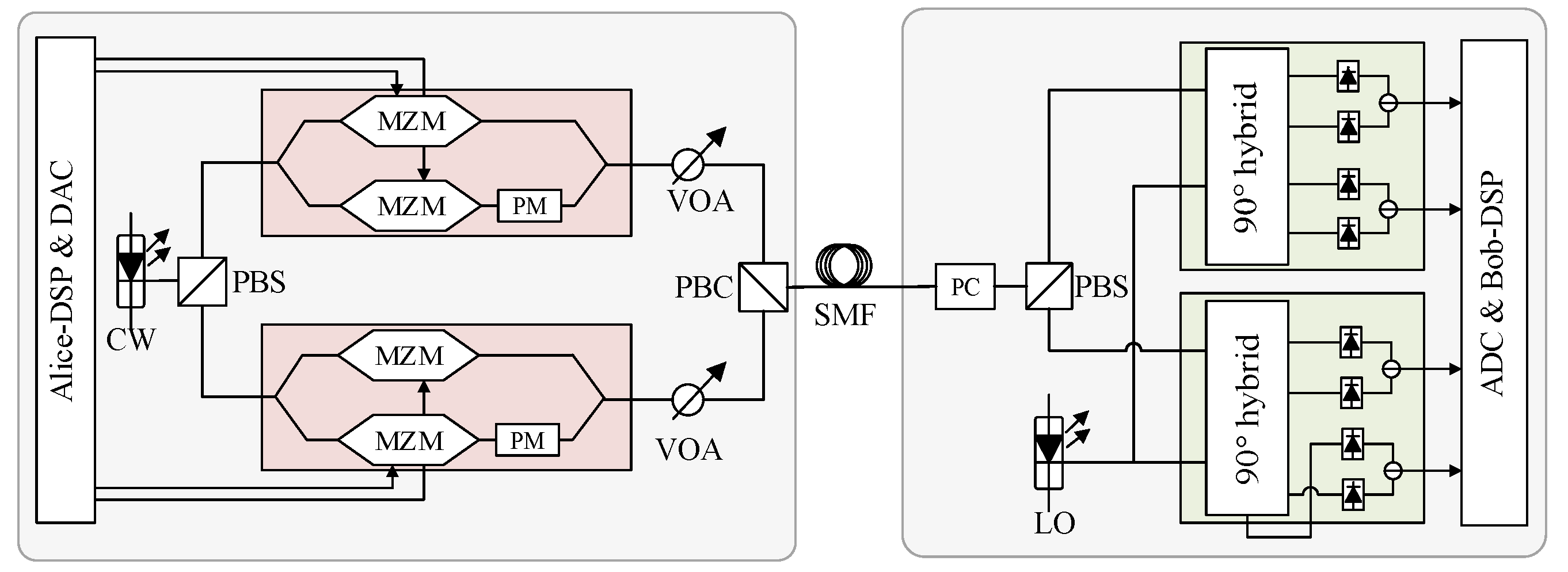
Figure 2.
DSP diagram of pilot-aided PDM-CVQKD system.
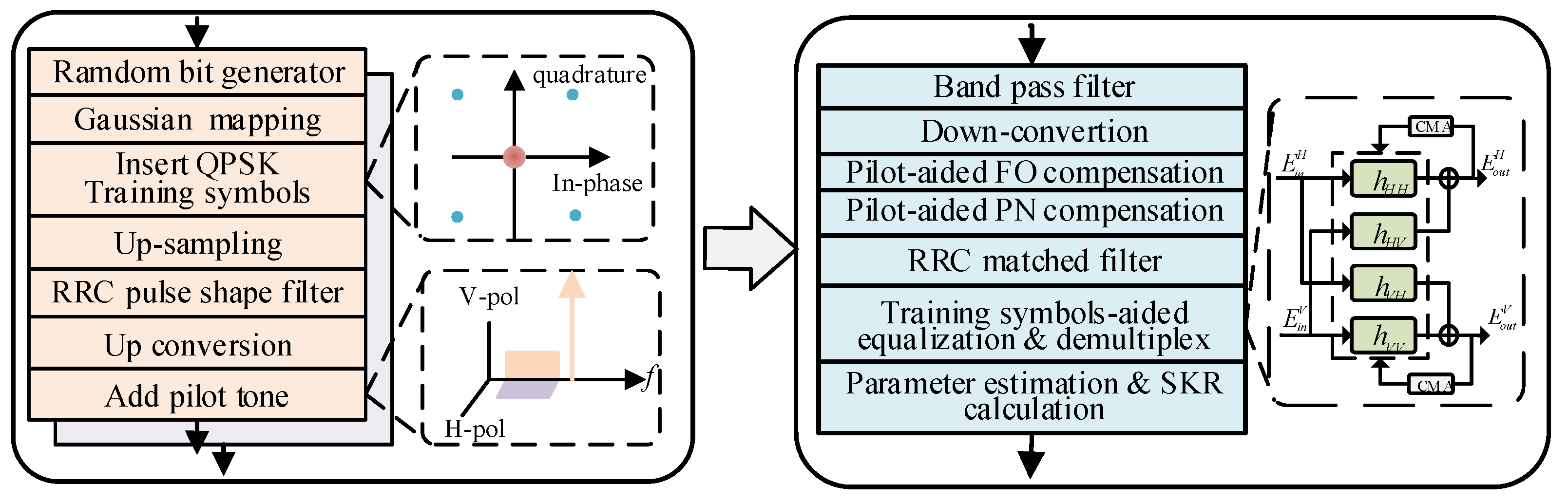
Figure 3.
Two schemes of TS-aided equalization. (a) scheme A based on fine-grained insertion strategy; (b) scheme B based on block insertion strategy.
Figure 3.
Two schemes of TS-aided equalization. (a) scheme A based on fine-grained insertion strategy; (b) scheme B based on block insertion strategy.
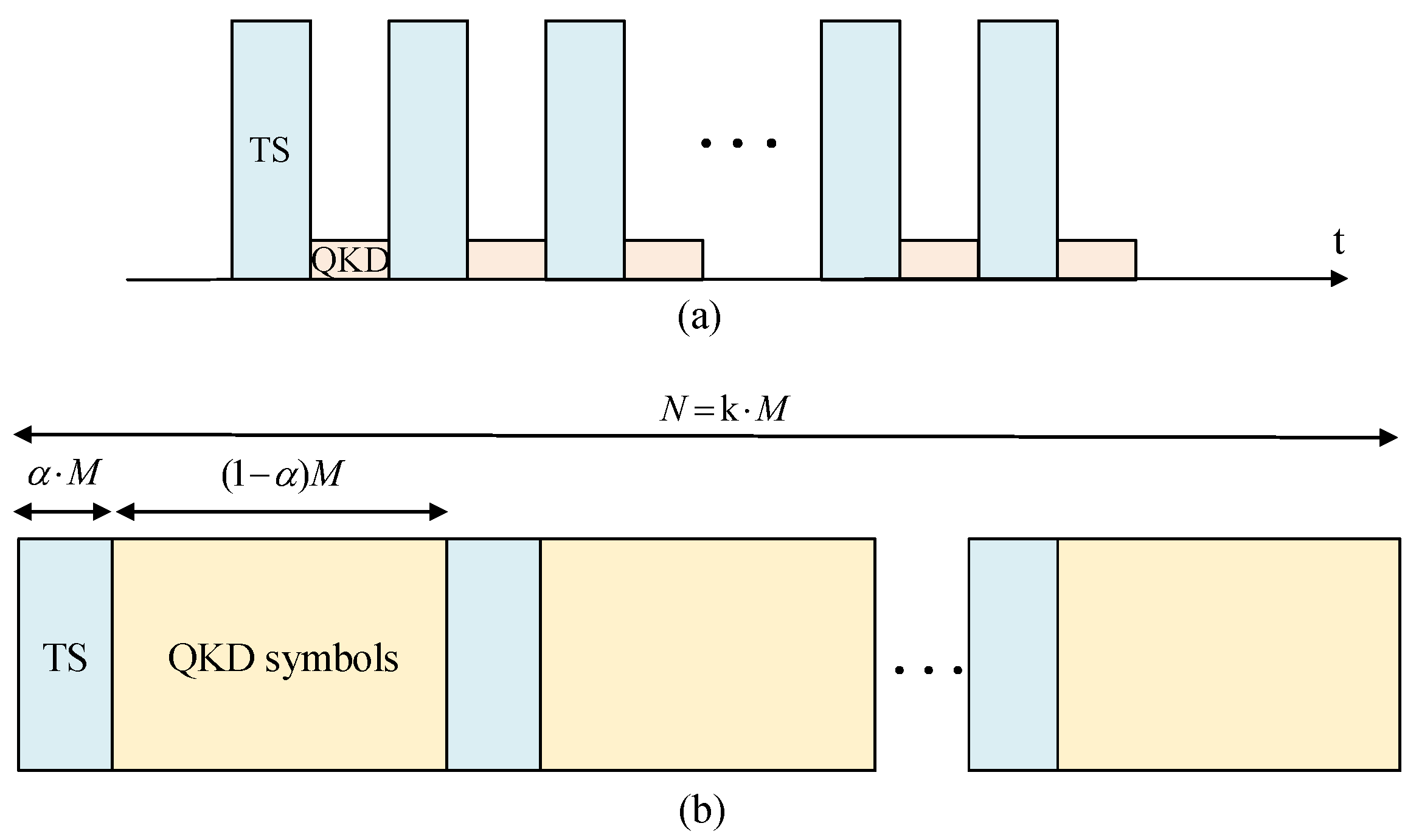
Figure 4.
of V-pol and H-pol estimated at transmitter/receiver with different pilot to quantum power ratio .
Figure 4.
of V-pol and H-pol estimated at transmitter/receiver with different pilot to quantum power ratio .
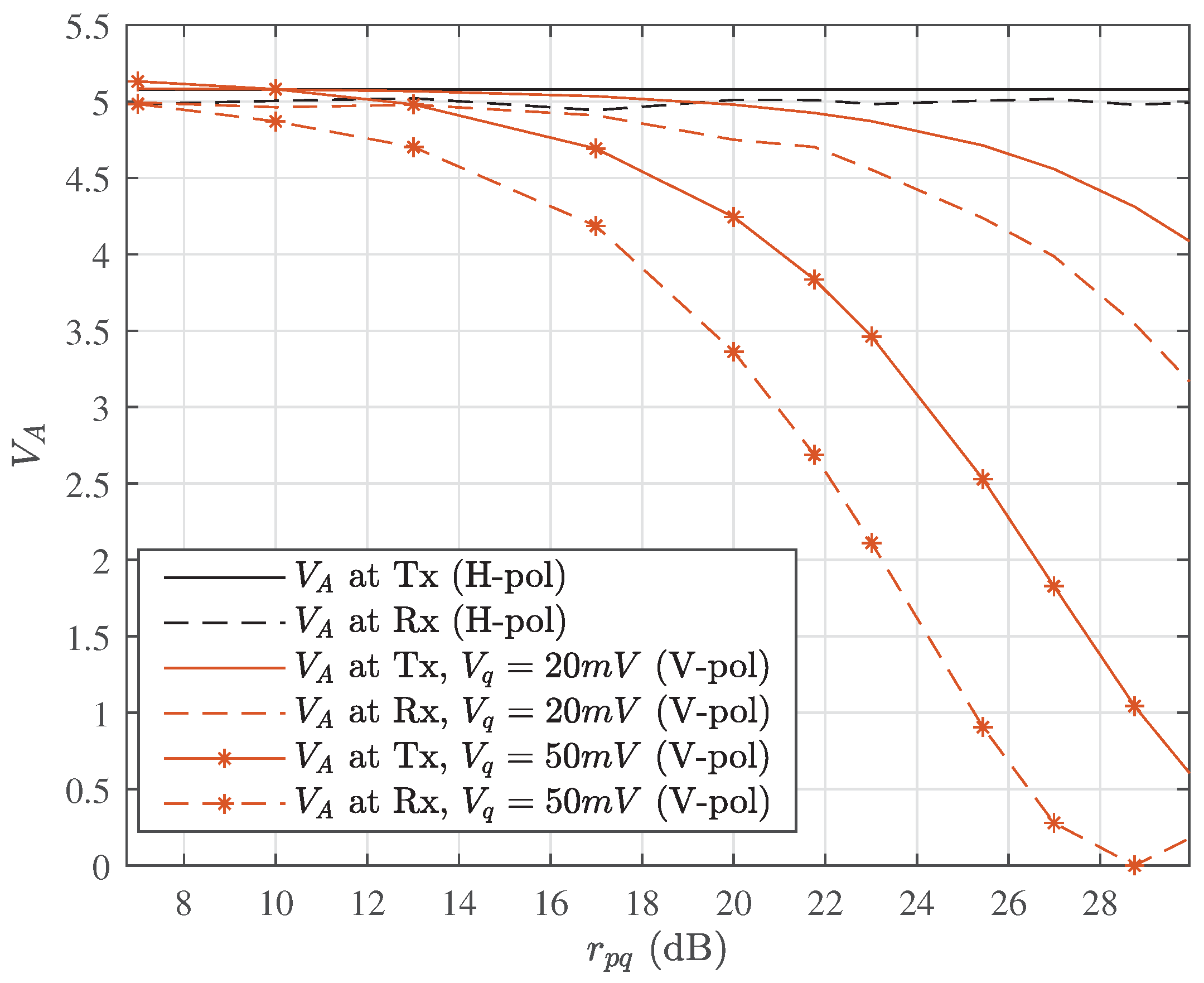
Figure 5.
The modulation-related excess noise under the impact of pilot tone (at the transmission distance of 20 Km).
Figure 5.
The modulation-related excess noise under the impact of pilot tone (at the transmission distance of 20 Km).
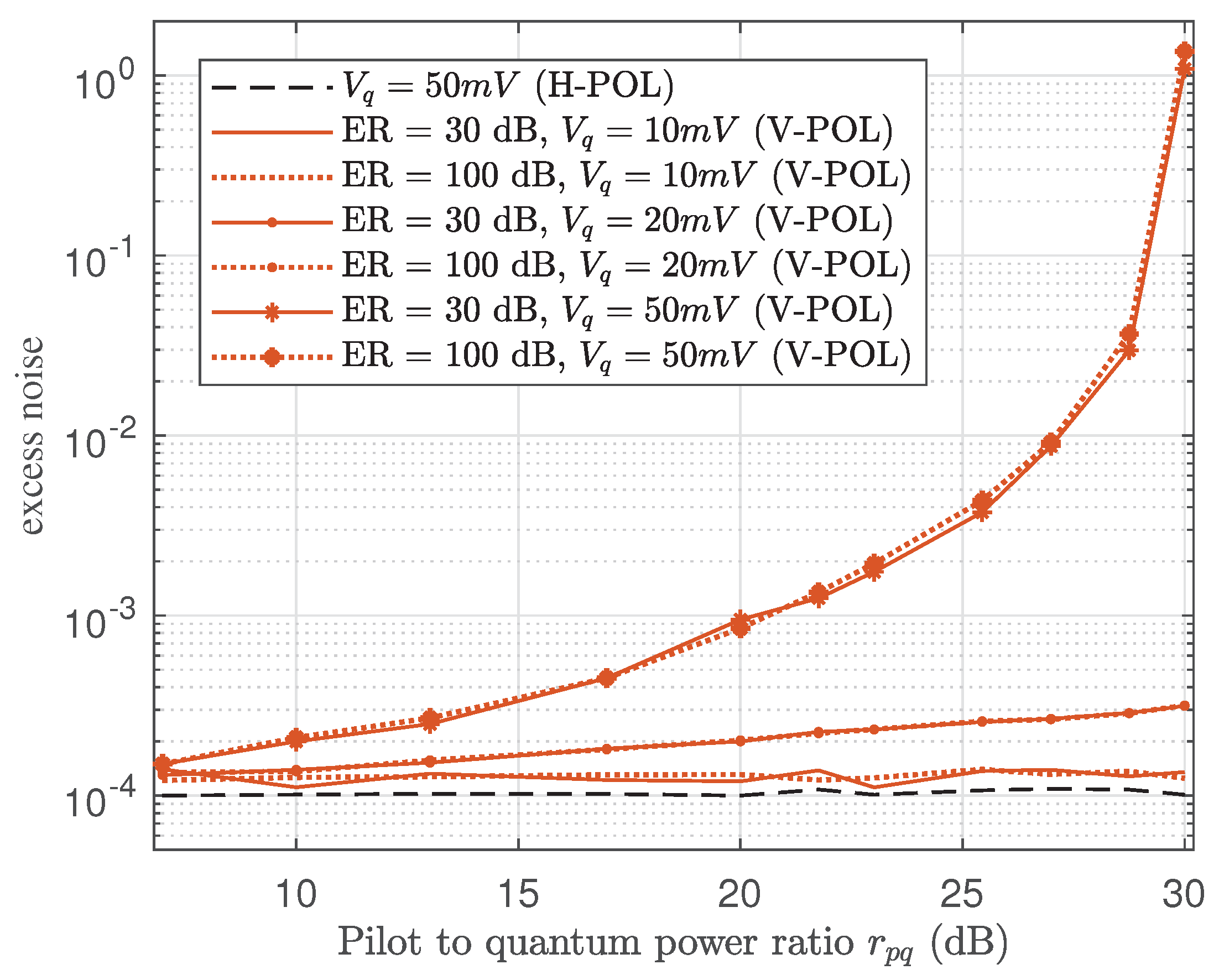
Figure 6.
and of V-pol and H-pol estimated at different bandwidth of FIR bandpass filter ( = 20 dB, at the transmission distance of 20 km).
Figure 6.
and of V-pol and H-pol estimated at different bandwidth of FIR bandpass filter ( = 20 dB, at the transmission distance of 20 km).
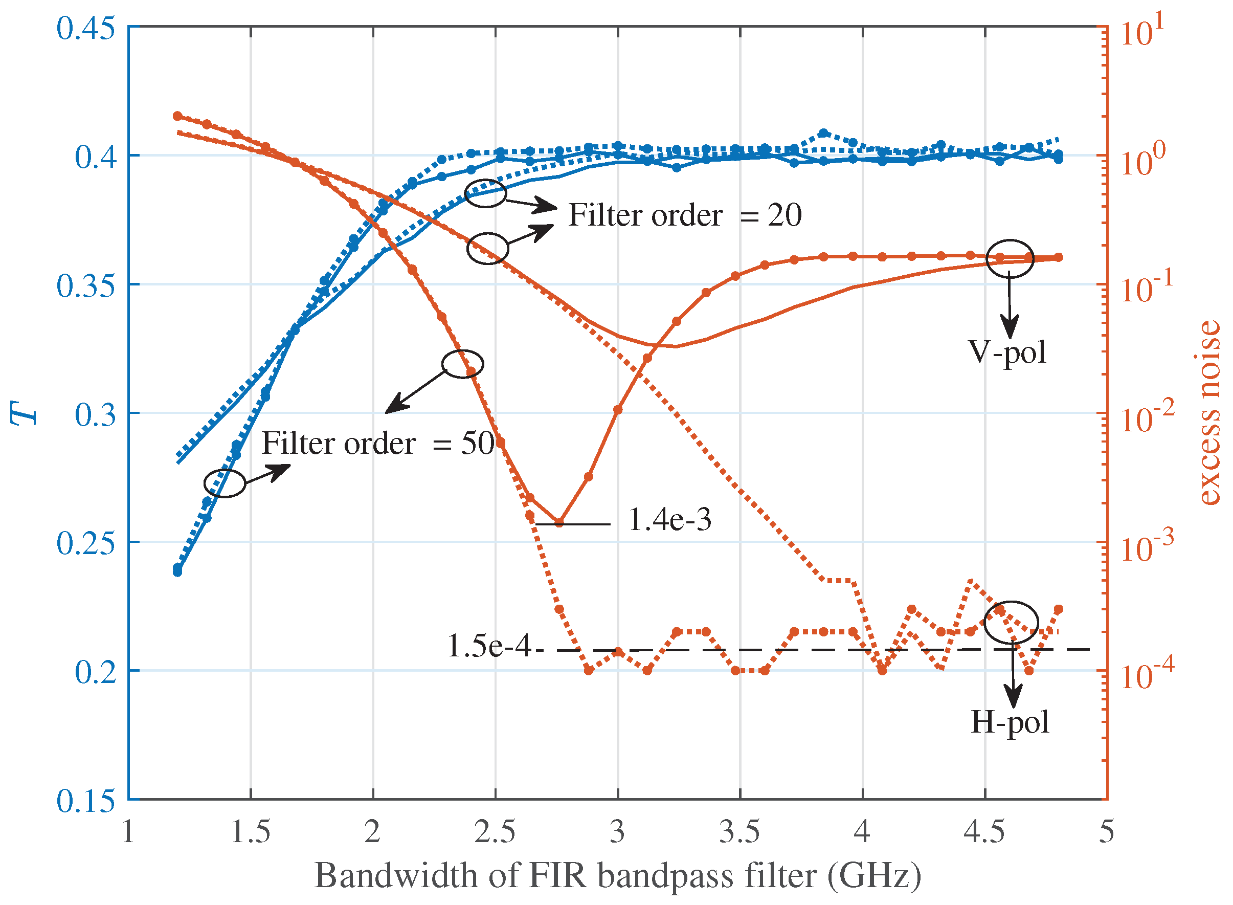
Figure 7.
Excess noise induced by pilot tone of V-pol and H-pol with different pilot to quantum power ratio (at the transmission distance of 20 km).
Figure 7.
Excess noise induced by pilot tone of V-pol and H-pol with different pilot to quantum power ratio (at the transmission distance of 20 km).
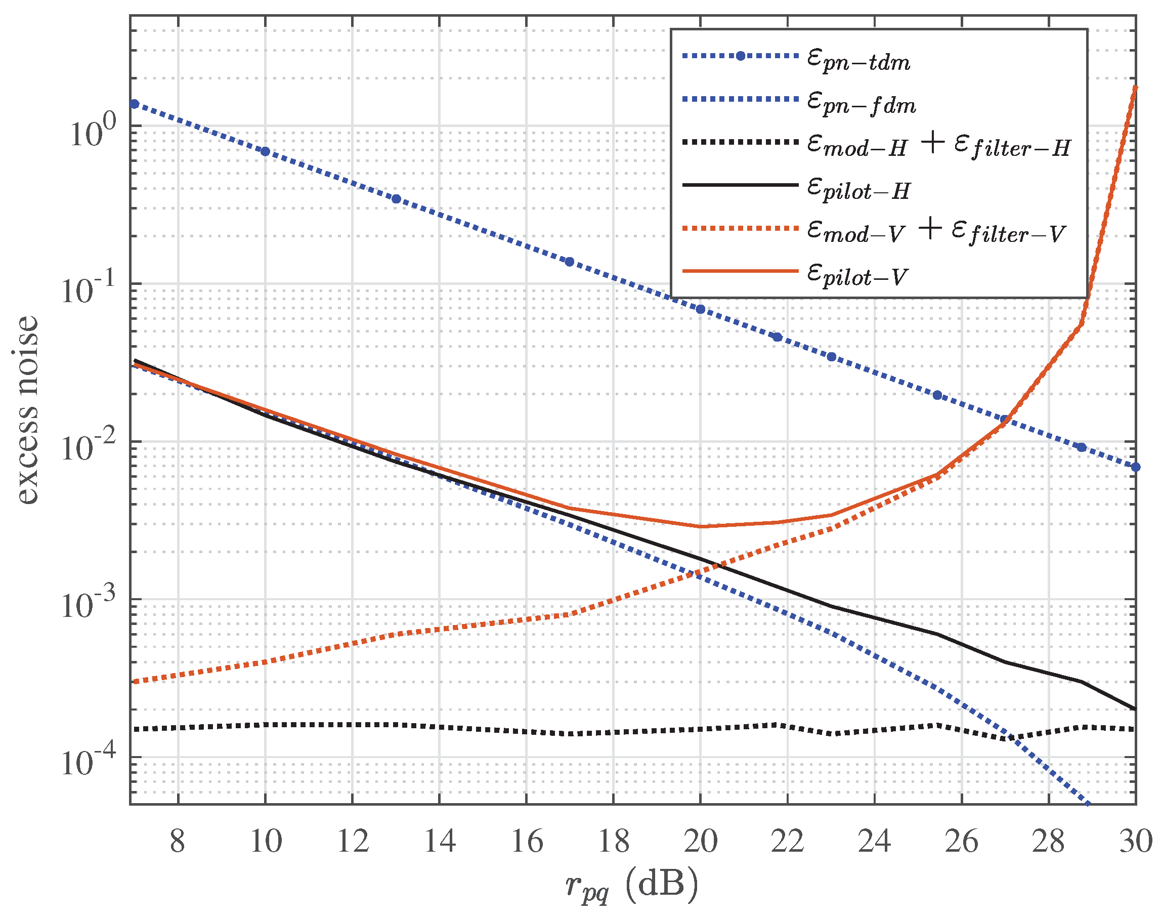
Figure 8.
vs. step size u at different tap number of equalizer in scheme B (at the transmission distance of 20 km).
Figure 8.
vs. step size u at different tap number of equalizer in scheme B (at the transmission distance of 20 km).
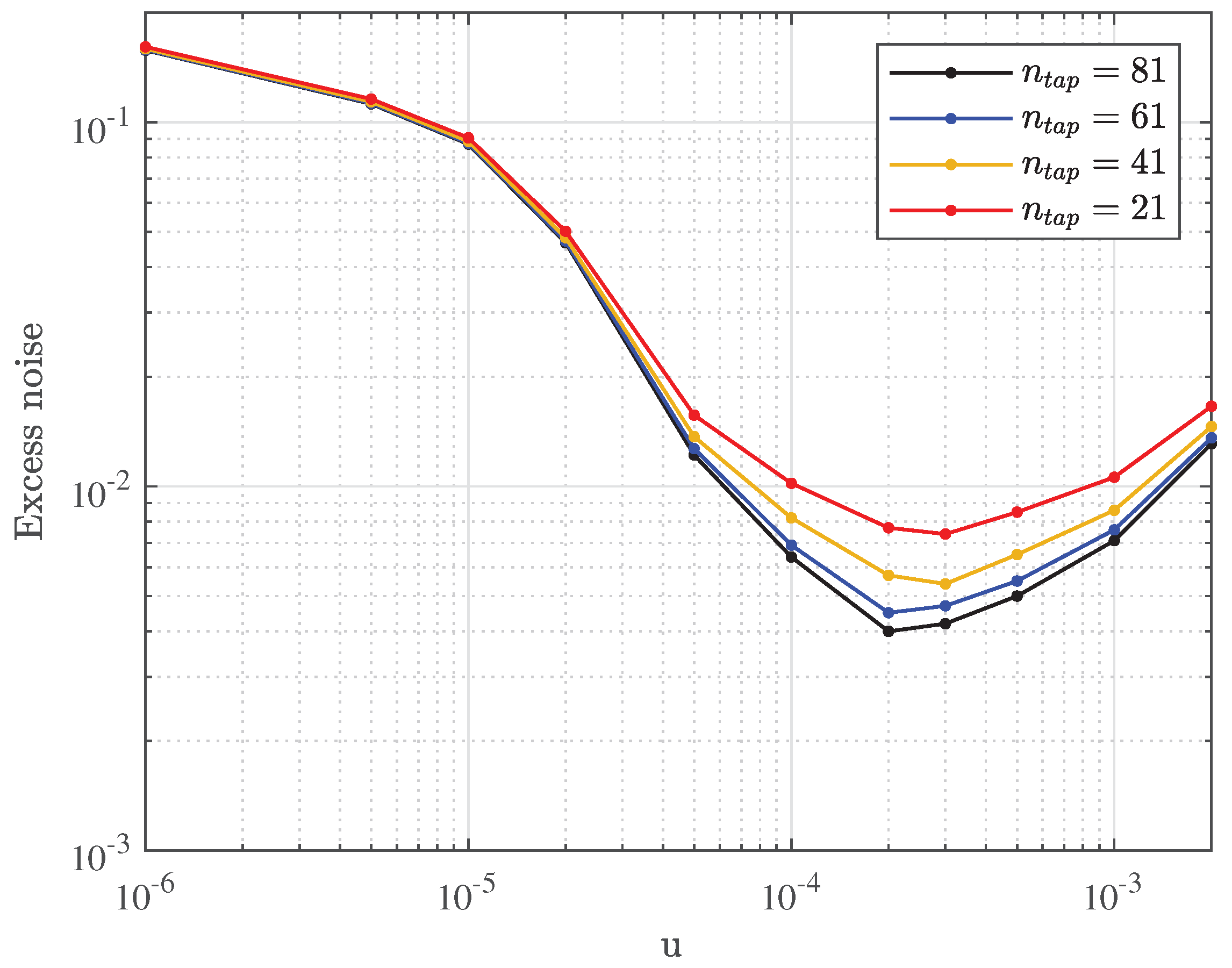
Figure 9.
The of each 5 blocks with different (at the transmission distance of 20 km).
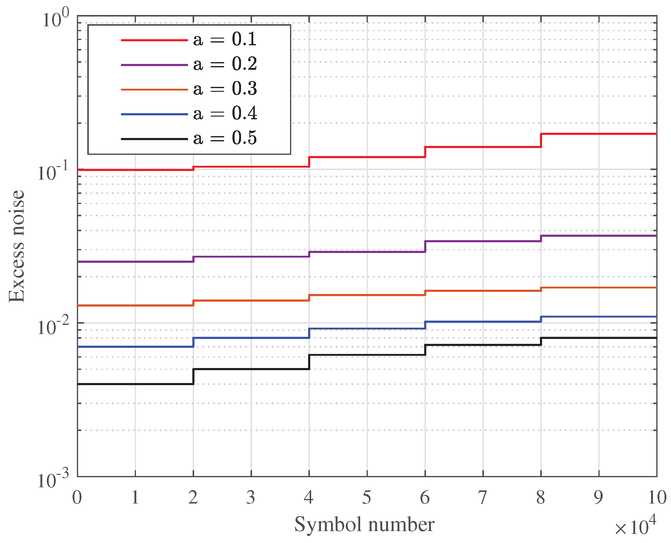
Figure 10.
The and SKR of scheme A and scheme B with respect to different (at the transmission distance of 20 km).
Figure 10.
The and SKR of scheme A and scheme B with respect to different (at the transmission distance of 20 km).
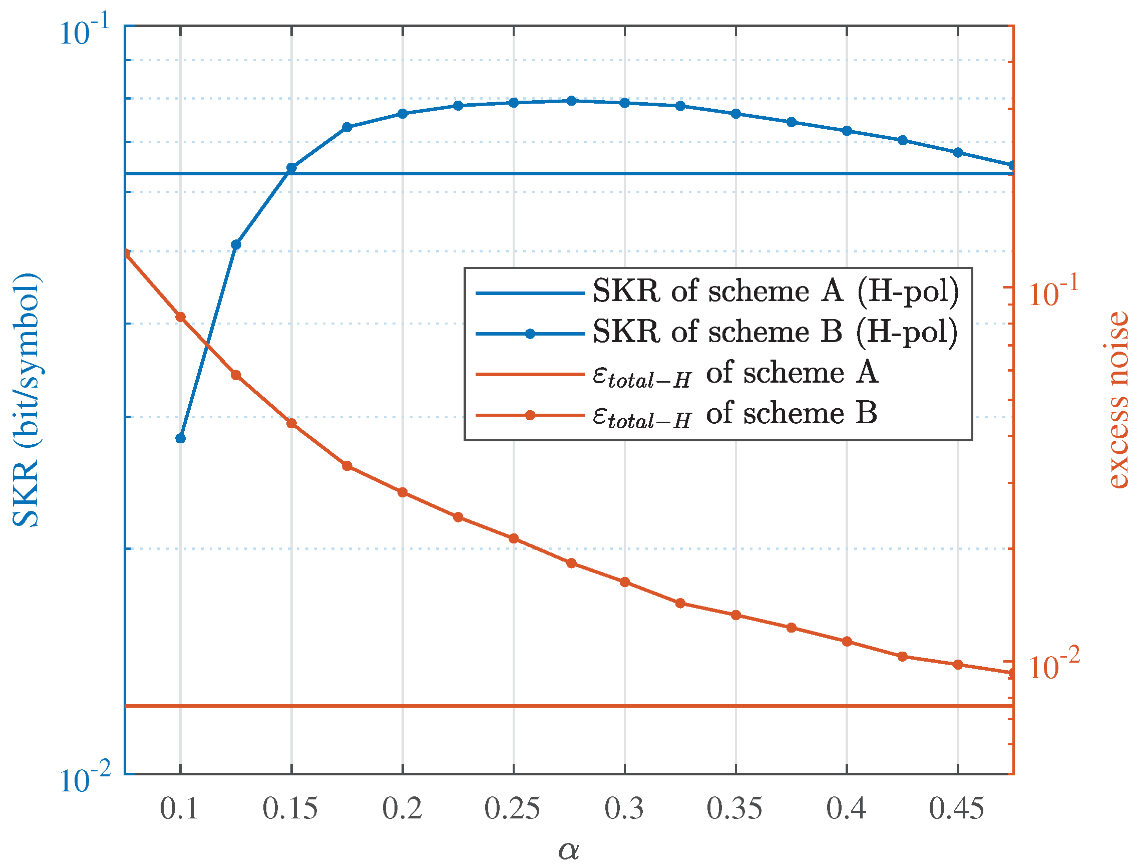
Figure 11.
of scheme A(B) and the corresponding optimal that maximize the SKR of scheme B at different transmission distances.
Figure 11.
of scheme A(B) and the corresponding optimal that maximize the SKR of scheme B at different transmission distances.

Figure 12.
The SKR (in bit/symbol) of scheme A and scheme B at different transmission distances.
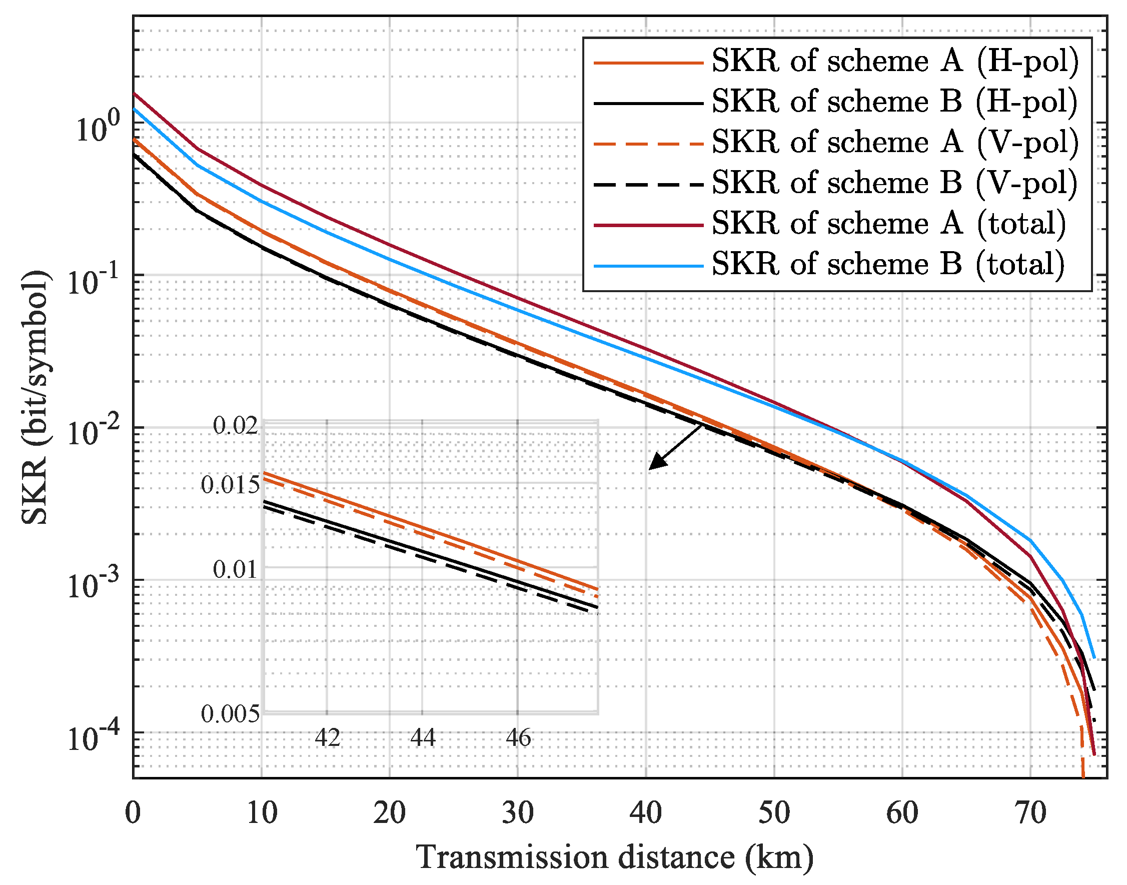

Table 1.
Main parameter setup of the numerical simulation.
| Blocklength N | 1e5 |
| Symbol rate | 2 GBaud |
| Roll-off factor | 0.2 |
| Up-convertion frequency | 1.5 GHz |
| Pilot frequency | 3.5 GHz |
| Frequency offset | 1 MHz |
| of MZM | 3 V |
| Modulation variance in SNU | 5 |
| Central frequency of lasers | 193.4 THz |
| Optical fiber loss coefficient | 0.2 dB/km |
| Bandwidth of receiver | 12 GHz |
| Quantum efficiency | 0.8 |
| Reconciliation efciency | 0.95 |
| Electronic noise variance ( in SNU) | 0.1 |
Disclaimer/Publisher’s Note: The statements, opinions and data contained in all publications are solely those of the individual author(s) and contributor(s) and not of MDPI and/or the editor(s). MDPI and/or the editor(s) disclaim responsibility for any injury to people or property resulting from any ideas, methods, instructions or products referred to in the content. |
© 2025 by the authors. Licensee MDPI, Basel, Switzerland. This article is an open access article distributed under the terms and conditions of the Creative Commons Attribution (CC BY) license (http://creativecommons.org/licenses/by/4.0/).
Copyright: This open access article is published under a Creative Commons CC BY 4.0 license, which permit the free download, distribution, and reuse, provided that the author and preprint are cited in any reuse.


